US5366497A - Non-invasive, radiolucent cardiac electrode - Google Patents
Non-invasive, radiolucent cardiac electrodeDownload PDFInfo
- Publication number
- US5366497A US5366497AUS07/860,995US86099592AUS5366497AUS 5366497 AUS5366497 AUS 5366497AUS 86099592 AUS86099592 AUS 86099592AUS 5366497 AUS5366497 AUS 5366497A
- Authority
- US
- United States
- Prior art keywords
- backing
- electrode
- pad
- patient
- defibrillator
- Prior art date
- Legal status (The legal status is an assumption and is not a legal conclusion. Google has not performed a legal analysis and makes no representation as to the accuracy of the status listed.)
- Expired - Lifetime
Links
- 230000000747cardiac effectEffects0.000titledescription15
- 230000004936stimulating effectEffects0.000claimsabstractdescription8
- 230000008878couplingEffects0.000claimsdescription18
- 238000010168coupling processMethods0.000claimsdescription18
- 238000005859coupling reactionMethods0.000claimsdescription18
- 238000000034methodMethods0.000claimsdescription17
- 238000012544monitoring processMethods0.000claimsdescription15
- 230000008569processEffects0.000claimsdescription15
- 210000004903cardiac systemAnatomy0.000claimsdescription12
- 230000001862defibrillatory effectEffects0.000claimsdescription11
- 239000000017hydrogelSubstances0.000claimsdescription11
- 229910001220stainless steelInorganic materials0.000claimsdescription11
- 229920001940conductive polymerPolymers0.000claimsdescription9
- 239000010935stainless steelSubstances0.000claimsdescription9
- 230000000994depressogenic effectEffects0.000claimsdescription8
- 239000002984plastic foamSubstances0.000claimsdescription7
- 239000000853adhesiveSubstances0.000claimsdescription6
- 230000001070adhesive effectEffects0.000claimsdescription6
- 229920002799BoPETPolymers0.000claimsdescription3
- 239000005041Mylar™Substances0.000claimsdescription3
- 238000003384imaging methodMethods0.000claimsdescription3
- 230000035939shockEffects0.000claimsdescription3
- 210000001835visceraAnatomy0.000claimsdescription3
- 238000003780insertionMethods0.000claims1
- 230000037431insertionEffects0.000claims1
- 229920000642polymerPolymers0.000description14
- 239000006260foamSubstances0.000description10
- 239000000499gelSubstances0.000description10
- 239000011888foilSubstances0.000description9
- 239000000463materialSubstances0.000description8
- 230000000638stimulationEffects0.000description5
- 238000002560therapeutic procedureMethods0.000description4
- 238000002399angioplastyMethods0.000description3
- 210000001367arteryAnatomy0.000description3
- 230000000977initiatory effectEffects0.000description3
- 229910052751metalInorganic materials0.000description3
- 239000002184metalSubstances0.000description3
- OKTJSMMVPCPJKN-UHFFFAOYSA-NCarbonChemical compound[C]OKTJSMMVPCPJKN-UHFFFAOYSA-N0.000description2
- 208000007536ThrombosisDiseases0.000description2
- 238000002583angiographyMethods0.000description2
- 230000004888barrier functionEffects0.000description2
- 230000015572biosynthetic processEffects0.000description2
- 230000015556catabolic processEffects0.000description2
- 239000002872contrast mediaSubstances0.000description2
- 210000004351coronary vesselAnatomy0.000description2
- 238000006731degradation reactionMethods0.000description2
- 238000003745diagnosisMethods0.000description2
- 238000010586diagramMethods0.000description2
- 239000010419fine particleSubstances0.000description2
- 238000002372labellingMethods0.000description2
- 230000007774longtermEffects0.000description2
- 239000004033plasticSubstances0.000description2
- 229920003023plasticPolymers0.000description2
- BASFCYQUMIYNBI-UHFFFAOYSA-NplatinumChemical compound[Pt]BASFCYQUMIYNBI-UHFFFAOYSA-N0.000description2
- 229910001369BrassInorganic materials0.000description1
- FAPWRFPIFSIZLT-UHFFFAOYSA-MSodium chlorideChemical compound[Na+].[Cl-]FAPWRFPIFSIZLT-UHFFFAOYSA-M0.000description1
- ATJFFYVFTNAWJD-UHFFFAOYSA-NTinChemical compound[Sn]ATJFFYVFTNAWJD-UHFFFAOYSA-N0.000description1
- RTAQQCXQSZGOHL-UHFFFAOYSA-NTitaniumChemical compound[Ti]RTAQQCXQSZGOHL-UHFFFAOYSA-N0.000description1
- 239000002998adhesive polymerSubstances0.000description1
- 229910052782aluminiumInorganic materials0.000description1
- XAGFODPZIPBFFR-UHFFFAOYSA-NaluminiumChemical compound[Al]XAGFODPZIPBFFR-UHFFFAOYSA-N0.000description1
- 230000003466anti-cipated effectEffects0.000description1
- 230000006793arrhythmiaEffects0.000description1
- 206010003119arrhythmiaDiseases0.000description1
- 239000010951brassSubstances0.000description1
- 229910052799carbonInorganic materials0.000description1
- 239000003575carbonaceous materialSubstances0.000description1
- 238000004140cleaningMethods0.000description1
- 239000011248coating agentSubstances0.000description1
- 238000000576coating methodMethods0.000description1
- 239000004020conductorSubstances0.000description1
- 238000011109contaminationMethods0.000description1
- 230000003247decreasing effectEffects0.000description1
- 238000000151depositionMethods0.000description1
- 230000000881depressing effectEffects0.000description1
- 238000001035dryingMethods0.000description1
- 230000005611electricityEffects0.000description1
- 230000005518electrochemistryEffects0.000description1
- 238000005516engineering processMethods0.000description1
- 239000004744fabricSubstances0.000description1
- 229910002804graphiteInorganic materials0.000description1
- 239000010439graphiteSubstances0.000description1
- 230000010247heart contractionEffects0.000description1
- 239000002085irritantSubstances0.000description1
- 231100000021irritantToxicity0.000description1
- 238000012986modificationMethods0.000description1
- 230000004048modificationEffects0.000description1
- 230000009972noncorrosive effectEffects0.000description1
- 238000004806packaging method and processMethods0.000description1
- 239000003973paintSubstances0.000description1
- 238000010422paintingMethods0.000description1
- 229910052697platinumInorganic materials0.000description1
- 238000003825pressingMethods0.000description1
- 239000011780sodium chlorideSubstances0.000description1
- 230000001954sterilising effectEffects0.000description1
- 238000004659sterilization and disinfectionMethods0.000description1
- 239000010936titaniumSubstances0.000description1
- 229910052719titaniumInorganic materials0.000description1
- XLYOFNOQVPJJNP-UHFFFAOYSA-NwaterSubstancesOXLYOFNOQVPJJNP-UHFFFAOYSA-N0.000description1
Images

Classifications
- A—HUMAN NECESSITIES
- A61—MEDICAL OR VETERINARY SCIENCE; HYGIENE
- A61N—ELECTROTHERAPY; MAGNETOTHERAPY; RADIATION THERAPY; ULTRASOUND THERAPY
- A61N1/00—Electrotherapy; Circuits therefor
- A61N1/18—Applying electric currents by contact electrodes
- A61N1/32—Applying electric currents by contact electrodes alternating or intermittent currents
- A61N1/36—Applying electric currents by contact electrodes alternating or intermittent currents for stimulation
- A61N1/36014—External stimulators, e.g. with patch electrodes
- A—HUMAN NECESSITIES
- A61—MEDICAL OR VETERINARY SCIENCE; HYGIENE
- A61B—DIAGNOSIS; SURGERY; IDENTIFICATION
- A61B5/00—Measuring for diagnostic purposes; Identification of persons
- A61B5/24—Detecting, measuring or recording bioelectric or biomagnetic signals of the body or parts thereof
- A61B5/25—Bioelectric electrodes therefor
- A61B5/251—Means for maintaining electrode contact with the body
- A61B5/257—Means for maintaining electrode contact with the body using adhesive means, e.g. adhesive pads or tapes
- A—HUMAN NECESSITIES
- A61—MEDICAL OR VETERINARY SCIENCE; HYGIENE
- A61B—DIAGNOSIS; SURGERY; IDENTIFICATION
- A61B5/00—Measuring for diagnostic purposes; Identification of persons
- A61B5/24—Detecting, measuring or recording bioelectric or biomagnetic signals of the body or parts thereof
- A61B5/25—Bioelectric electrodes therefor
- A61B5/263—Bioelectric electrodes therefor characterised by the electrode materials
- A61B5/268—Bioelectric electrodes therefor characterised by the electrode materials containing conductive polymers, e.g. PEDOT:PSS polymers
- A—HUMAN NECESSITIES
- A61—MEDICAL OR VETERINARY SCIENCE; HYGIENE
- A61B—DIAGNOSIS; SURGERY; IDENTIFICATION
- A61B5/00—Measuring for diagnostic purposes; Identification of persons
- A61B5/24—Detecting, measuring or recording bioelectric or biomagnetic signals of the body or parts thereof
- A61B5/25—Bioelectric electrodes therefor
- A61B5/271—Arrangements of electrodes with cords, cables or leads, e.g. single leads or patient cord assemblies
- A61B5/273—Connection of cords, cables or leads to electrodes
- A—HUMAN NECESSITIES
- A61—MEDICAL OR VETERINARY SCIENCE; HYGIENE
- A61B—DIAGNOSIS; SURGERY; IDENTIFICATION
- A61B5/00—Measuring for diagnostic purposes; Identification of persons
- A61B5/24—Detecting, measuring or recording bioelectric or biomagnetic signals of the body or parts thereof
- A61B5/25—Bioelectric electrodes therefor
- A61B5/279—Bioelectric electrodes therefor specially adapted for particular uses
- A61B5/28—Bioelectric electrodes therefor specially adapted for particular uses for electrocardiography [ECG]
- A—HUMAN NECESSITIES
- A61—MEDICAL OR VETERINARY SCIENCE; HYGIENE
- A61N—ELECTROTHERAPY; MAGNETOTHERAPY; RADIATION THERAPY; ULTRASOUND THERAPY
- A61N1/00—Electrotherapy; Circuits therefor
- A61N1/02—Details
- A61N1/04—Electrodes
- A61N1/0404—Electrodes for external use
- A61N1/0472—Structure-related aspects
- A61N1/0492—Patch electrodes
- A61N1/0496—Patch electrodes characterised by using specific chemical compositions, e.g. hydrogel compositions, adhesives
- A—HUMAN NECESSITIES
- A61—MEDICAL OR VETERINARY SCIENCE; HYGIENE
- A61N—ELECTROTHERAPY; MAGNETOTHERAPY; RADIATION THERAPY; ULTRASOUND THERAPY
- A61N1/00—Electrotherapy; Circuits therefor
- A61N1/18—Applying electric currents by contact electrodes
- A61N1/32—Applying electric currents by contact electrodes alternating or intermittent currents
- A61N1/38—Applying electric currents by contact electrodes alternating or intermittent currents for producing shock effects
- A61N1/39—Heart defibrillators
- A61N1/3904—External heart defibrillators [EHD]
- A—HUMAN NECESSITIES
- A61—MEDICAL OR VETERINARY SCIENCE; HYGIENE
- A61N—ELECTROTHERAPY; MAGNETOTHERAPY; RADIATION THERAPY; ULTRASOUND THERAPY
- A61N1/00—Electrotherapy; Circuits therefor
- A61N1/18—Applying electric currents by contact electrodes
- A61N1/32—Applying electric currents by contact electrodes alternating or intermittent currents
- A61N1/36—Applying electric currents by contact electrodes alternating or intermittent currents for stimulation
- A61N1/362—Heart stimulators
- A61N1/3625—External stimulators
Definitions
- This inventionrelates to a non-invasive cardiac electrode, and more specifically, to a non-invasive, radiolucent cardiac electrode which is capable of conducting energy at a level sufficient for cardiac stimulation.
- Prior art non-invasive electrodes adapted for defibrillating or pacing the hearttypically comprise a skin-contacting pad which is laminated to a metal foil conductive backing which in turn is electrically coupled to a source of defibrillating or pacing energy.
- the purpose of the foil backingis to distribute the energy from the source substantially uniformly over the pad before it is delivered to the patient, thereby eliminating burns or the like which could occur if the energy were to be delivered in a more concentrated fashion.
- this foil backinghas been viewed as a desirable, and even necessary, component of prior art non-invasive electrodes.
- a problem with the prior art foil backingis that it may interfere with the ability to image an aspect of the patient's circulatory system, such as the arteries of the heart, with a fluoroscope or the like, when electrodes containing the prior art backing are positioned on the patient's skin so that multiple cardiac stimulation therapies can be rapidly delivered to the patient should he or she suffer an arrhythmia during the imaging process.
- the interferencemay occur because the prior art foil backing typically creates shadows or blemishes in the images of the internal organs, all of which may impede diagnosis of the patient's condition.
- the practitionerIn the areas of cardiac catheterization, angiography, and angioplasty, for example, the practitioner must be able to see the angiography dye or the catheter to determine the extent of the presence of plaque or other irregularities in the patient's arteries.
- the foil backingcan shadow or block the view of the patient's arteries, thereby leading to an incomplete or improper diagnosis.
- Prior art radiolucent electrodesare also available which utilize a conductive rubber backing instead of metal foil.
- these rubber backing materialsare suitable only for high impedance external pacing systems. They are not suitable for defibrillation as they have too high an impedance.
- the term "radiolucent"is defined as the quality of being capable of providing a low enough attenuation of X-irradiation such that body structures such as coronary arteries imaged with intraluminal contrast material may be visualized through the electrode without significant degradation in image quality so as to make the image uninterpretable with respect to luminal irregularities, angioplasty outcome, thrombus formation, or vessel occlusion.
- a second approachinvolves forming the conductive element of the electrode by applying fine particles of an electrically conductive material, such as carbon, to an electrode base. Again, this approach could not successively utilized in a stimulation electrode, since the layer of fine particles would not be capable of conducting the relatively high levels of energy required.
- a third approachinvolves forming the conductive element from a porous carbonaceous material or graphite sheet.
- a problem with this approachis that the resulting electrode would have too high an impedance when used for defibrillation in that the high levels of energy would cause the electrode to heat up too much.
- a radiolucent non-invasive electrode for stimulating a patient's heartcomprising a pad adapted for contacting the patient's skin over a first surface, a radiolucent conductive mesh backing adapted to contact and substantially cover a second surface of the pad, the backing in one exemplary embodiment comprising a mesh made of stainless steel wires, the mesh having about 15 to 50 wires/inch, and the wires having a diameter of between about 5 to 10 mils, the electrode further comprising means for electrically coupling the radiolucent backing to stimulating means configured to produce electrical impulses adapted to stimulate the patient's heart.
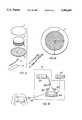
- FIG. 1is a drawing showing an exploded view of an electrode incorporating the teachings of the subject invention
- FIG. 2is a drawing showing the face of an electrode incorporating the teachings of the subject invention
- FIG. 3is a block diagram of a cardiac system incorporating an electrode of the subject invention
- FIG. 4is a drawing of an electrode pair, where each electrode in the pair incorporates the teachings of the subject invention
- FIG. 5is a drawing of a cabling system adapted for use with an electrode incorporating the teachings of the subject invention.
- FIG. 6is a drawing of an alternate cabling system adapted for use with an electrode incorporating the teachings of the subject invention.
- FIG. 1A diagram of an electrode incorporating the teachings of the subject invention is illustrated in FIG. 1.
- the electrodeadvantageously comprises peelable cover 1, conductive adhesive polymer pad 2, radiolucent backing 3, plastic foam cover 4, insulated wire 5, and wire retainer 6.
- An object of the electrodeis to be radiolucent and still be capable of delivering stimulating electrical impulses to the patient's heart, either pacing pulses or defibrillating pulses, substantially uniformly over the face of the electrode pad.
- the peelable coveris advantageously attached to the polymer pad to keep any foreign material off of a first surface of the pad, which surface is adapted to contact the patient's skin, and can be peeled off when the surface of the electrode is about to be applied to the patient's skin.
- a second surface of the polymer padis advantageously adapted to be placed in contact with the radiolucent backing such that the backing substantially covers the second surface.
- the backingin turn, is adapted to be placed in contact with the plastic foam cover.
- the plastic foam coverhas a hole in it exposing part of the radiolucent backing, and the insulated wire has an exposed proximal end (with the other end being referred to as the distal end) which is inserted into the hole and electrically coupled to the radiolucent backing, such that the plastic cover is sandwiched between the mesh and the wire.
- the conductive polymer padis advantageously 25 mils (1 mil equals 0.001 inch) thick.
- the foam backingis advantageously comprised of a rubber closed-cell foam such as MED-416 (available from the FASSON specialty tape division of AVERY INTERNATIONAL).
- the foamis advantageously closed-cell, i.e., has air pockets completely surrounded by foam, so that no foreign material can get through it. This is to be contrasted with an open-cell material such as a sponge, which allows foreign material such as water to pass completely through it.
- the foam backingis advantageously covered with a medical grade adhesive which will enable the foam backing to adhere directly to the radiolucent backing, and to the human body in those areas which extend beyond the polymer pad. In the example of FIG. 1, the foam backing is advantageously 1/16 of an inch (0.062 inches) thick.
- the overall diameter of the electrode face, identified with A in the figure,is advantageously about 13 cm. (9 cm. for a pediatric electrode), giving rise to an overall area for the electrode face of about 132.67 sq. cm. (63.58 sq. cm. for a pediatric electrode).
- the diameter of the polymer pad, identified with B in the figure,is advantageously about 10 cm. (6.5 cm. for a pediatric electrode), giving rise to an area of about 78.58 sq. cm. for the pad (33.17 sq. cm. for a pediatric electrode).
- the wire retaineris placed over the hole in the foam backing after the exposed end of the wire has been inserted and electrically coupled to the radiolucent backing.
- the wire retaineris coated with an adhesive so that it will adhere to the foam backing and reduce strain on the wire.
- the padsare preferably composed of an adhesive conductive polymer (also known as a hydrogel) such as Promeon's RG-XX conductive polymer.
- the RG-XX polymeris advantageous since it is non-hyperallergenic and also has been shown to be a non-irritant to the skin.
- Conductive polymersare the result of recent, significant advancements in conductive gel technology. A recent article providing more information about conductive polymers is R. Kaner and A. MacDiarmid, Plastics That Conduct Electricity, Scientific American, Vol. 258, No. 2 (Feb. 1988), which is hereby fully incorporated by reference herein as though set forth in full.
- the polymer padis comprised of Promeon's RG62-D hydrogel since this particular hydrogel has been found to be compatible with an advantageous embodiment of the radiolucent backing (in which the backing is made of stainless steel--see below).
- Other hydrogelssuch as Promeon's RG63T and RG63B, as well as hydrogels offered by other manufacturers, may be suitable depending on the configuration.
- Conductive polymersoffer several advantages over existing saline-based gels. First, these polymers have the consistency of rubber, eliminating the smearing problem associated with prior art gels. In addition, because of their rubber-like consistency, these polymers have a longer shelf life than the prior art gels, and they do not leave a residue once they are removed from contact with a patient's skin. Finally, the polymers need not be integrated with a sponge in order to achieve their shape.
- the polymers used for the electrodescan be chosen to be inherently adhesive, so that the pads will adhere to a patient's skin over their entire surface area compared with the prior art gel electrodes, which only adhere to the patient's skin at a ring surrounding the pad. As a result, the polymer pads will adhere better, eliminating the problem of burning and electrode movement associated with prior art electrodes.
- these polymershave better electrical characteristics than the prior art gels. They are effectively lower in impedance when placed in contact with the patient's skin, since their superior adhesion prevents portions of the electrode from lifting off the patient's skin. Lifting would result in a conductive path to the skin having a high effective impedance at these areas. As a result, less voltage is required to administer a particular stimulating current pulse, and the voltage generator in the cardiac system to which the electrode is integrated, and the entire cardiac system in general, can be made smaller, more compact, and less costly. Also, the polymers, because of their different electrochemistry, will depolarize much faster than prior art gels. In fact, the polymers will typically depolarize in one-half the time it takes for a prior art gel to depolarize.
- the insulated wire 5is advantageously 18-20 gauge wire which preconnects the wire to a standard connector for interfacing to a cabling system for coupling the electrode to a defibrillator (see below).
- radiolucentis defined to be the quality of producing a low enough attenuation of X-irradiation such that body structures such as coronary arteries imaged with intraluminal contrast material may be visualized through the backing without significant degradation in image quality so as to make the image uninterpretable with respect to luminal irregularities, angioplasty outcome, thrombus formation, or vessel occlusion.
- This backingmust fulfill three requirements simultaneously which are t cross-purposes. First and foremost, it must be radiolucent. Second, it should be pliable enough to conform to the human body. Third, it must be capable of delivering a sufficient energy for defibrillation, up to 360 Joules, substantially uniformly over the face of the electrode pad.
- the meshis made from low-resistance, non-corrosive, pliable metal wires, advantageously stainless steel, although other examples are possible, including aluminum, brass, titanium, or platinum, depending on compatibility with hydrogel.
- the diameter of the wiresare preferably between about 5 to 10 mils, and most preferably, are less than about 9 mils.
- the number of wires per inch, which determines the spacing between the wiresis preferably between about 15 to 50 wires/in, and most preferably between about 20-40 wires/in.
- all these parametersshould be chosen so that the percentage of open space of the mesh is greater than about 50%.
- the meshis advantageously cut into an 8.5 cm. (6 cm. for a pediatric electrode) diameter circle with the rough edge covered with a mylar ring to prevent the mesh from puncturing the other materials in the electrode.
- an electrode incorporating the mesh backing described aboveis most appropriate for standby or emergency cardiac situations where defibrillation or countershock is required.
- a stainless steel mesh and a hydrogel chosen for compatibility with stainless steelare not in fact compatible with each other under long term pacing conditions.
- the hydrogel which is the lowest impedance and the most suitable for external pacingis not in fact compatible with stainless steel under long-term pacing conditions.
- Embedding the mesh in a low impedance conductive rubberprovides a barrier between the hydrogel and the mesh.
- This combination of materialsdifferentiates the backing from current electrodes adapted for pacing (discussed in the background section) which are manufactured with a backing made only of conductive rubber.
- Electrodesare advantageously disposable, and are bound and packaged together in pairs by a connector system, with the distal ends of the insulated wires 5 emanating from each electrode joined together by a connector.
- One electrodeis typically labeled "Anterior” and the other electrode is typically labeled “Apex.”
- packaginga completed pair of electrodes is advantageously packaged in a poly/foil laminate bag and heat sealed. The purpose of this package is to seal the product to prevent contamination and keep it clean. This product does not require sterilization, so the only requirement of the package is to provide protection and a moisture barrier.
- FIG. 4A pair of electrodes is illustrated in FIG. 4, in which compared to previous figures, like elements are referenced with like identifying numerals.
- the "Anterior" electrode of the pairis referenced with identifying numeral 30a while the “Apex” electrode of the pair is referenced with identifying numeral 30b.
- the foam backings for the two electrodesare referenced with numerals 4a and 4b, respectively, the mesh backing for the "Apex" electrode, with numeral 3b, the insulated wires for the pair, with numerals 5a and 5b, respectively, and the wire retainers for the pair, with numerals 6a and 6b, respectively.
- labels for each electrodeidentified with numerals 7a and 7b, respectively, for use in labelling the electrodes with the manufacturer's name, trade logos, or the like, or for labelling one electrode as "Apex” and the other as “Anterior.”
- connector 8for binding the distal ends of the insulated wires 5a and 5b together and for facilitating connection to a cabelling system.
- FIG. 5A cabelling system for coupling a pair of the electrodes to a defibrillator is illustrated in FIG. 5. As shown, this system comprises connector 9 for connecting the cabling system to connector 8 of the electrode pair. Also shown is cable 10, for coupling connector 9 (and therefore the pair of electrodes) to shock plate 31.
- Shock plate 31comprises a base 13 with member 32 placed over the base and configured to form defibrillator paddle wells 11, which in turn, are configured so that the defibrillator paddles fit snugly into the wells. Also shown are paddle contacts 12 situated in the wells for making electrical contact with the defibrillator paddles.
- the operatorselects the skin sites onto which the electrodes are to be applied.
- the skin siteis then prepared by cleaning and drying the skin with a rough cloth.
- the peelable release lineris removed from the electrode pads and the adhesive side of the pads are rolled onto the skin of the patient.
- the insulated wires 5a and 5bare connected to the cabling system by means of connectors 8 and 9, and the defibrillator paddles are placed in paddle wells 11.
- the defibrillatoris charged as usual and a discharge is then initiated by depressing discharge switches on the defibriilator paddles, causing the defibrillator to discharge through the paddles and the cabling system into the electrodes.
- FIG. 6An alternate cabling system for both defibrillating and monitoring the patient through the subject electrodes is illustrated in FIG. 6.
- this cabling systemcomprises connector 17 adapted to couple to connector 8 of the electrode pair, and cable 19 for coupling the connector 17 (and therefore the pair of electrodes) to switch box 33.
- Switch box 33comprises a housing 23 and defibrillator buttons 24 for initiating defibrillation.
- monitoring cable 25 and defibrillator cable 26Coupled to the switch box are monitoring cable 25 and defibrillator cable 26. Also shown are defibrillation connector 28 for coupling the switch box to a defibrillator, and monitoring connector 27 for coupling the switch box to a monitor.
- the switch boxis configured to receive any electrical impulses originating from the patient through the electrodes (by means of connector 17 and cable 19), and delivering the same to monitoring cable 25, and is also configured to deliver any electrical impulses originating from a defibrillator through cable 26 to the electrodes through cable 19.
- the insulated wires 5a and 5bare connected to the cabelling system by means of connectors 8 and 17, and the cabelling system, in turn, is connected to a defibrillator and monitor by means of cables 25 and 26, and connectors 27 and 28.
- ECG monitor signals obtained through the electrodescan then be observed by the operator on the monitor.
- the defibrillatoris charged as usual and a discharge is initiated by pressing pushbuttons 24, which causes the defibrillator to discharge through the cabling system into the electrodes.
- FIG. 3A cardiac system including the subject electrodes which allows for simultaneous pacing, defibrillation, and monitoring is illustrated in FIG. 3.
- the pacing/defibrillation embodiment of the electrodes described previouslyin which the mesh backing is enclosed in a low impedance conductive rubber.
- the systempreferably comprises stimulating means 101, optional monitoring means 102, and electrode means 103.
- stimulating means 101further comprises defibrillator 201, defibrillator paddles 202, defibrillator input plates 203, and external pacemaker/defibrillator pass-through 204.
- the defibrillator paddlesare advantageously electrically coupled to the defibrillator
- the defibrillator input platesare advantageously electrically coupled to the pass-through, which in turn, is advantageously electrically coupled to monitoring means.
- the electrode meansis advantageously coupled to the pass-through.
- defibrillator 201is a conventional defibrillator which delivers defibrillating energy by means of defibrillator paddles 202.
- monitoring means 102is a conventional ECG monitor.
- Electrode means 103is preferably a pair of non-invasive radiolucent electrodes incorporating the teachings of the subject invention.
- Pass-through 204is an external cardiac pacemaker that provides for the combined use of defibrillation and external cardiac pacing for emergency cardiac treatment.
- the deviceenables pacing or defibrillating current to be delivered through the electrodes.
- External cardiac pacingis an old and proven technique for initiating a heart contraction.
- the defibrillator input plates located on the top of the pass-throughare spring loaded and provide the ability to defibrillate and pace through the same set of electrodes.
- an intermittent toneis sounded.
- the tonebecomes constant, indicating that both plates are down and that defibrillation may follow.
- Defibrillating energyis then generated and delivered by the defibrillator through the pass-through and to the patient through the electrodes.
- the platesare designed to be depressed by the paddles of any defibrillator with no gel required. After the plates have been depressed by means of the defibrillating paddles, the plates will spring back up and reconnect the pacemaker circuitry to the patient. When both plates are not fully depressed, pacing may follow. Pacing energy is then generated and delivered by the pass-through to the electrodes and ultimately the patient.
- the pass-throughalso provides a connection for an optional two lead ECG monitor through the pass-through straight to the electrodes. If the monitor is added to the system, then the electrodes should be constructed with multiple pads in accordance with the teachings of U.S. Pat. Nos. 4,955,381 and 5,080,099, both of which are hereby fully incorporated by reference herein as though set forth in full. In this instance, the foil backings of the multiple pads should be replaced with the radiolucent backings of the subject invention.
- the default mode of operation of the systemis to pace the heart. As indicated above, the pass-through will generate and deliver external cardiac pacing energy through the electrodes to a patient automatically provided both input plates are not fully depressed. Should defibrillation be necessary, the paddles should be firmly pressed against the plates until both are depressed and the resultant tone is constant, and the defibrillator will generate and deliver defibrillating energy through the electrodes to the patient. Additional monitoring can also be optionally provided by the system in accordance with the teachings in U.S. Pat. Nos. 4,955,381 and 5,080,099.
Landscapes
- Health & Medical Sciences (AREA)
- Life Sciences & Earth Sciences (AREA)
- Public Health (AREA)
- Engineering & Computer Science (AREA)
- Biomedical Technology (AREA)
- Veterinary Medicine (AREA)
- Animal Behavior & Ethology (AREA)
- General Health & Medical Sciences (AREA)
- Heart & Thoracic Surgery (AREA)
- Biophysics (AREA)
- Radiology & Medical Imaging (AREA)
- Nuclear Medicine, Radiotherapy & Molecular Imaging (AREA)
- Cardiology (AREA)
- Physics & Mathematics (AREA)
- Pathology (AREA)
- Medical Informatics (AREA)
- Molecular Biology (AREA)
- Surgery (AREA)
- Chemical & Material Sciences (AREA)
- Chemical Kinetics & Catalysis (AREA)
- General Chemical & Material Sciences (AREA)
- Electrotherapy Devices (AREA)
Abstract
Description
Claims (38)
Priority Applications (2)
| Application Number | Priority Date | Filing Date | Title |
|---|---|---|---|
| US07/860,995US5366497A (en) | 1992-03-31 | 1992-03-31 | Non-invasive, radiolucent cardiac electrode |
| US07/930,003US5356428A (en) | 1992-03-31 | 1992-08-13 | Non-invasive, radiolucent electrode |
Applications Claiming Priority (1)
| Application Number | Priority Date | Filing Date | Title |
|---|---|---|---|
| US07/860,995US5366497A (en) | 1992-03-31 | 1992-03-31 | Non-invasive, radiolucent cardiac electrode |
Related Child Applications (1)
| Application Number | Title | Priority Date | Filing Date |
|---|---|---|---|
| US07/930,003Continuation-In-PartUS5356428A (en) | 1992-03-31 | 1992-08-13 | Non-invasive, radiolucent electrode |
Publications (1)
| Publication Number | Publication Date |
|---|---|
| US5366497Atrue US5366497A (en) | 1994-11-22 |
Family
ID=25334595
Family Applications (1)
| Application Number | Title | Priority Date | Filing Date |
|---|---|---|---|
| US07/860,995Expired - LifetimeUS5366497A (en) | 1992-03-31 | 1992-03-31 | Non-invasive, radiolucent cardiac electrode |
Country Status (1)
| Country | Link |
|---|---|
| US (1) | US5366497A (en) |
Cited By (29)
| Publication number | Priority date | Publication date | Assignee | Title |
|---|---|---|---|---|
| US5571165A (en)* | 1995-12-08 | 1996-11-05 | Ferrari; R. Keith | X-ray transmissive transcutaneous stimulating electrode |
| EP0778046A2 (en) | 1995-12-08 | 1997-06-11 | R. Keith Ferrari | X-ray transmissive transcutaneous stimulating electrode |
| US5724984A (en)* | 1995-01-26 | 1998-03-10 | Cambridge Heart, Inc. | Multi-segment ECG electrode and system |
| US5791944A (en)* | 1996-06-18 | 1998-08-11 | Cambridge Heart, Inc. | Electrode connector |
| US5817151A (en)* | 1996-06-04 | 1998-10-06 | Survivalink Corporation | Circuit detectable packaged medical electrodes |
| US5904712A (en)* | 1997-06-12 | 1999-05-18 | Axelgaard Manufacturing Co., Ltd. | Current-controlling electrode |
| EP0985426A2 (en) | 1998-08-26 | 2000-03-15 | Zmd Corporation | Reducing skin damage in use of medical electrodes |
| US6546285B1 (en)* | 1997-03-07 | 2003-04-08 | Cardiac Science, Inc. | Long term wear electrode for defibrillation system |
| US6564079B1 (en) | 2000-07-27 | 2003-05-13 | Ckm Diagnostics, Inc. | Electrode array and skin attachment system for noninvasive nerve location and imaging device |
| US20030171798A1 (en)* | 2002-03-08 | 2003-09-11 | Medtronic Physio-Control Manufacturing Corp. | Therapy and monitoring electrodes with patient accommodating features and electrode sensing |
| US20030171797A1 (en)* | 2002-03-08 | 2003-09-11 | Nova Richard C. | Therapy and monitoring electrodes with patient accommodating features |
| US6751501B1 (en) | 1997-07-17 | 2004-06-15 | Science Medicus, Inc. | Method and apparatus for myocardial control |
| US20050010274A1 (en)* | 2001-09-14 | 2005-01-13 | Zoll Medical Corporation | Electrode assemblies |
| US20050015134A1 (en)* | 2003-07-18 | 2005-01-20 | 3M Innovative Properties Company | Biomedical electrode with current spreading layer |
| US7069074B2 (en) | 2001-11-07 | 2006-06-27 | Medtronic Emergency Response Systems, Inc. | Easy-to-use electrode and package |
| US20070255382A1 (en)* | 2006-04-27 | 2007-11-01 | Peter Meyer | Electrode pad packaging systems and methods |
| US20100072060A1 (en)* | 2008-09-25 | 2010-03-25 | Tyco Healthcare Group Lp | Biomedical Electrode and Method of Formation Thereof |
| US20100075532A1 (en)* | 2008-09-25 | 2010-03-25 | Tyco Healthcare Group Lp | Fluorescent Marker for Detecting Gel or Lack of Gel |
| US20100076294A1 (en)* | 2008-09-25 | 2010-03-25 | Tyco Healthcare Group Lp | System and Method of Prepping Skin Prior to Electrode Application |
| USD639243S1 (en) | 2006-03-29 | 2011-06-07 | Nuvasive, Inc. | Electrode connector |
| US20120016259A1 (en)* | 2003-12-23 | 2012-01-19 | Ib Rask Odderson | Nerve Path Adaptable Nerve Testing Device |
| US20150112176A1 (en)* | 2012-05-28 | 2015-04-23 | Nipro Corporation | Electrode pad for use on living organism |
| US9226680B1 (en) | 2013-02-12 | 2016-01-05 | David Kendricks | Patient electrode connectors for electrocardiograph monitoring system |
| US10154942B2 (en) | 2000-02-04 | 2018-12-18 | Zoll Medical Corporation | Integrated resuscitation |
| EP2109397B1 (en)* | 2007-01-25 | 2020-02-19 | LifeSync Corporation | Radiolucent assembly for connecting electrode or sensor |
| US10953234B2 (en) | 2015-08-26 | 2021-03-23 | Element Science, Inc. | Wearable devices |
| US11185709B2 (en) | 2014-02-24 | 2021-11-30 | Element Science, Inc. | External defibrillator |
| US11253715B2 (en) | 2018-10-10 | 2022-02-22 | Element Science, Inc. | Wearable medical device with disposable and reusable components |
| US20220142603A1 (en)* | 2019-07-26 | 2022-05-12 | Fujifilm Corporation | Stethoscope |
Citations (36)
| Publication number | Priority date | Publication date | Assignee | Title |
|---|---|---|---|---|
| US1212541A (en)* | 1916-01-28 | 1917-01-16 | Allen Chapman Company | Therapeutical appliance. |
| US1498059A (en)* | 1921-09-10 | 1924-06-17 | Executor John B Abbott | Therapeutic electrode |
| US1989282A (en)* | 1933-08-19 | 1935-01-29 | Gen Electric X Ray Corp | Electrode |
| US2536271A (en)* | 1945-07-11 | 1951-01-02 | Hartford Nat Bank & Trust Co | Device for the medical treatment of persons with high-frequency energy and electrodefor such a device |
| US2632447A (en)* | 1948-05-12 | 1953-03-24 | Cowan Mfg Co | Electric applicator |
| US3085577A (en)* | 1961-06-12 | 1963-04-16 | Vector Mfg Company Inc | Body electrode |
| US3472233A (en)* | 1966-12-02 | 1969-10-14 | Robert I Sarbacher | Electrical muscle stimulator |
| US3817252A (en)* | 1972-05-08 | 1974-06-18 | Medtronic Inc | Electrode for transcutaneous stimulation |
| US4030509A (en)* | 1975-09-30 | 1977-06-21 | Mieczyslaw Mirowski | Implantable electrodes for accomplishing ventricular defibrillation and pacing and method of electrode implantation and utilization |
| US4050453A (en)* | 1976-02-03 | 1977-09-27 | Concept, Inc. | Radiotransparent electrode |
| US4187853A (en)* | 1978-11-06 | 1980-02-12 | Barbanel Sidney M | Electrode implanting apparatus with optimum location probe |
| US4207904A (en)* | 1977-01-28 | 1980-06-17 | Greene Ronald W | Constant power density electrode adapted to be useful in bio-medical applications |
| US4226247A (en)* | 1978-08-21 | 1980-10-07 | Hauser Laboratories | Biological electrode |
| US4239046A (en)* | 1978-09-21 | 1980-12-16 | Ong Lincoln T | Medical electrode |
| US4243052A (en)* | 1979-01-08 | 1981-01-06 | Stimtech, Inc. | Disposable electrode |
| US4243051A (en)* | 1979-01-08 | 1981-01-06 | Johnson & Johnson | Disposable electrode |
| US4257424A (en)* | 1979-04-30 | 1981-03-24 | Ndm Corporation | X-ray transparent medical electrode |
| US4270549A (en)* | 1979-04-30 | 1981-06-02 | Mieczyslaw Mirowski | Method for implanting cardiac electrodes |
| US4291707A (en)* | 1979-04-30 | 1981-09-29 | Mieczyslaw Mirowski | Implantable cardiac defibrillating electrode |
| US4314095A (en)* | 1979-04-30 | 1982-02-02 | Mieczyslaw Mirowski | Device and method for making electrical contact |
| US4370984A (en)* | 1979-04-30 | 1983-02-01 | Ndm Corporation | X-Ray transparent medical electrode |
| US4442315A (en)* | 1980-11-17 | 1984-04-10 | Fukuda Denshi Kabushiki Kaisha | X-Ray transmissive electrode-shielded wire assembly and manufacture thereof |
| US4576170A (en)* | 1980-07-09 | 1986-03-18 | Micro-Circuits Company | Heart monitor and defibrillator device |
| US4674511A (en)* | 1979-04-30 | 1987-06-23 | American Hospital Supply Corporation | Medical electrode |
| US4685467A (en)* | 1985-07-10 | 1987-08-11 | American Hospital Supply Corporation | X-ray transparent medical electrodes and lead wires and assemblies thereof |
| US4722354A (en)* | 1985-06-14 | 1988-02-02 | Jens Axelgaard | Electrical stimulation electrode |
| US4748983A (en)* | 1985-08-27 | 1988-06-07 | Kureha Kagaku Kogyo Kabushiki Kaisha | X-ray transmissive electrode for a living body |
| US4765341A (en)* | 1981-06-22 | 1988-08-23 | Mieczyslaw Mirowski | Cardiac electrode with attachment fin |
| US4800887A (en)* | 1985-08-27 | 1989-01-31 | Kureha Kagaku Kogyo Kabushiki Kaisha | X ray-transparent electrode for a living body |
| US4817594A (en)* | 1985-04-18 | 1989-04-04 | Laszlo Juhasz | Wound dressings with electrically conductive layers |
| US4827932A (en)* | 1987-02-27 | 1989-05-09 | Intermedics Inc. | Implantable defibrillation electrodes |
| US4846178A (en)* | 1986-06-05 | 1989-07-11 | Beijing Information Technology Institute | Electric field therapeutic apparatus |
| US4893626A (en)* | 1986-12-11 | 1990-01-16 | Henley Ernest J | Electrode for electrotherapy, electrosurgery and monitoring |
| US4938231A (en)* | 1985-10-22 | 1990-07-03 | Telectronics N.V. | Defibrillator electrode |
| US4955381A (en)* | 1988-08-26 | 1990-09-11 | Cardiotronics, Inc. | Multi-pad, multi-function electrode |
| US5148805A (en)* | 1991-02-11 | 1992-09-22 | Kas Products, Inc. | Defibrillator pad system and method for using same |
- 1992
- 1992-03-31USUS07/860,995patent/US5366497A/ennot_activeExpired - Lifetime
Patent Citations (37)
| Publication number | Priority date | Publication date | Assignee | Title |
|---|---|---|---|---|
| US1212541A (en)* | 1916-01-28 | 1917-01-16 | Allen Chapman Company | Therapeutical appliance. |
| US1498059A (en)* | 1921-09-10 | 1924-06-17 | Executor John B Abbott | Therapeutic electrode |
| US1989282A (en)* | 1933-08-19 | 1935-01-29 | Gen Electric X Ray Corp | Electrode |
| US2536271A (en)* | 1945-07-11 | 1951-01-02 | Hartford Nat Bank & Trust Co | Device for the medical treatment of persons with high-frequency energy and electrodefor such a device |
| US2632447A (en)* | 1948-05-12 | 1953-03-24 | Cowan Mfg Co | Electric applicator |
| US3085577A (en)* | 1961-06-12 | 1963-04-16 | Vector Mfg Company Inc | Body electrode |
| US3472233A (en)* | 1966-12-02 | 1969-10-14 | Robert I Sarbacher | Electrical muscle stimulator |
| US3817252A (en)* | 1972-05-08 | 1974-06-18 | Medtronic Inc | Electrode for transcutaneous stimulation |
| US4030509A (en)* | 1975-09-30 | 1977-06-21 | Mieczyslaw Mirowski | Implantable electrodes for accomplishing ventricular defibrillation and pacing and method of electrode implantation and utilization |
| US4050453A (en)* | 1976-02-03 | 1977-09-27 | Concept, Inc. | Radiotransparent electrode |
| US4207904A (en)* | 1977-01-28 | 1980-06-17 | Greene Ronald W | Constant power density electrode adapted to be useful in bio-medical applications |
| US4226247A (en)* | 1978-08-21 | 1980-10-07 | Hauser Laboratories | Biological electrode |
| US4239046A (en)* | 1978-09-21 | 1980-12-16 | Ong Lincoln T | Medical electrode |
| US4187853A (en)* | 1978-11-06 | 1980-02-12 | Barbanel Sidney M | Electrode implanting apparatus with optimum location probe |
| US4243052A (en)* | 1979-01-08 | 1981-01-06 | Stimtech, Inc. | Disposable electrode |
| US4243051A (en)* | 1979-01-08 | 1981-01-06 | Johnson & Johnson | Disposable electrode |
| US4291707A (en)* | 1979-04-30 | 1981-09-29 | Mieczyslaw Mirowski | Implantable cardiac defibrillating electrode |
| US4257424A (en)* | 1979-04-30 | 1981-03-24 | Ndm Corporation | X-ray transparent medical electrode |
| US4314095A (en)* | 1979-04-30 | 1982-02-02 | Mieczyslaw Mirowski | Device and method for making electrical contact |
| US4370984A (en)* | 1979-04-30 | 1983-02-01 | Ndm Corporation | X-Ray transparent medical electrode |
| US4674511A (en)* | 1979-04-30 | 1987-06-23 | American Hospital Supply Corporation | Medical electrode |
| US4270549A (en)* | 1979-04-30 | 1981-06-02 | Mieczyslaw Mirowski | Method for implanting cardiac electrodes |
| US4576170A (en)* | 1980-07-09 | 1986-03-18 | Micro-Circuits Company | Heart monitor and defibrillator device |
| US4442315A (en)* | 1980-11-17 | 1984-04-10 | Fukuda Denshi Kabushiki Kaisha | X-Ray transmissive electrode-shielded wire assembly and manufacture thereof |
| US4539995A (en)* | 1980-11-17 | 1985-09-10 | Fukuda Denshi Kabushiki Kaisha | X-Ray transmissive electrode-shielded wire assembly |
| US4765341A (en)* | 1981-06-22 | 1988-08-23 | Mieczyslaw Mirowski | Cardiac electrode with attachment fin |
| US4817594A (en)* | 1985-04-18 | 1989-04-04 | Laszlo Juhasz | Wound dressings with electrically conductive layers |
| US4722354A (en)* | 1985-06-14 | 1988-02-02 | Jens Axelgaard | Electrical stimulation electrode |
| US4685467A (en)* | 1985-07-10 | 1987-08-11 | American Hospital Supply Corporation | X-ray transparent medical electrodes and lead wires and assemblies thereof |
| US4748983A (en)* | 1985-08-27 | 1988-06-07 | Kureha Kagaku Kogyo Kabushiki Kaisha | X-ray transmissive electrode for a living body |
| US4800887A (en)* | 1985-08-27 | 1989-01-31 | Kureha Kagaku Kogyo Kabushiki Kaisha | X ray-transparent electrode for a living body |
| US4938231A (en)* | 1985-10-22 | 1990-07-03 | Telectronics N.V. | Defibrillator electrode |
| US4846178A (en)* | 1986-06-05 | 1989-07-11 | Beijing Information Technology Institute | Electric field therapeutic apparatus |
| US4893626A (en)* | 1986-12-11 | 1990-01-16 | Henley Ernest J | Electrode for electrotherapy, electrosurgery and monitoring |
| US4827932A (en)* | 1987-02-27 | 1989-05-09 | Intermedics Inc. | Implantable defibrillation electrodes |
| US4955381A (en)* | 1988-08-26 | 1990-09-11 | Cardiotronics, Inc. | Multi-pad, multi-function electrode |
| US5148805A (en)* | 1991-02-11 | 1992-09-22 | Kas Products, Inc. | Defibrillator pad system and method for using same |
Non-Patent Citations (6)
| Title |
|---|
| Cardiotronics' 510K Premarket Notification for the Model #210 Stealth Defib. Pad, Filed with the FDA on Sep. 27, 1990. |
| Cardiotronics' 510K Premarket Notification for the Model #310 Stealth-Trode+RF Defibrillation Pads, Filed with the FDA on May 4, 1992. |
| Cardiotronics 510K Premarket Notification for the Model 210 Stealth Defib. Pad, Filed with the FDA on Sep. 27, 1990.* |
| Cardiotronics 510K Premarket Notification for the Model 310 Stealth Trode RF Defibrillation Pads, Filed with the FDA on May 4, 1992.* |
| Physio Control packing and labeling for electrodes, pacing only.* |
| Physio-Control packing and labeling for electrodes, pacing only. |
Cited By (60)
| Publication number | Priority date | Publication date | Assignee | Title |
|---|---|---|---|---|
| US5724984A (en)* | 1995-01-26 | 1998-03-10 | Cambridge Heart, Inc. | Multi-segment ECG electrode and system |
| EP0778046A2 (en) | 1995-12-08 | 1997-06-11 | R. Keith Ferrari | X-ray transmissive transcutaneous stimulating electrode |
| US5733324A (en)* | 1995-12-08 | 1998-03-31 | Ferrari; R. Keith | X-ray transmissive transcutaneous stimulating electrode |
| US5571165A (en)* | 1995-12-08 | 1996-11-05 | Ferrari; R. Keith | X-ray transmissive transcutaneous stimulating electrode |
| US5817151A (en)* | 1996-06-04 | 1998-10-06 | Survivalink Corporation | Circuit detectable packaged medical electrodes |
| US5791944A (en)* | 1996-06-18 | 1998-08-11 | Cambridge Heart, Inc. | Electrode connector |
| US6546285B1 (en)* | 1997-03-07 | 2003-04-08 | Cardiac Science, Inc. | Long term wear electrode for defibrillation system |
| US9089718B2 (en) | 1997-03-07 | 2015-07-28 | Cardiac Science Corporation | Defibrillation system |
| US5904712A (en)* | 1997-06-12 | 1999-05-18 | Axelgaard Manufacturing Co., Ltd. | Current-controlling electrode |
| US6038485A (en)* | 1997-06-12 | 2000-03-14 | Axelgaard Manufacturing Co., Ltd. | Current-controlling electrode |
| US6751501B1 (en) | 1997-07-17 | 2004-06-15 | Science Medicus, Inc. | Method and apparatus for myocardial control |
| US6280463B1 (en) | 1998-08-26 | 2001-08-28 | Zmd Corporation | Reducing skin damage in use of medical electrodes |
| US6453205B1 (en) | 1998-08-26 | 2002-09-17 | Michael R. Dupelle | Reducing skin damage in use of medical electrodes |
| EP0985426A2 (en) | 1998-08-26 | 2000-03-15 | Zmd Corporation | Reducing skin damage in use of medical electrodes |
| US10154942B2 (en) | 2000-02-04 | 2018-12-18 | Zoll Medical Corporation | Integrated resuscitation |
| US10154941B2 (en) | 2000-02-04 | 2018-12-18 | Zoll Medical Corporation | Integrated resuscitation |
| US6609018B2 (en) | 2000-07-27 | 2003-08-19 | Ckm Diagnostics, Inc. | Electrode array and sensor attachment system for noninvasive nerve location and imaging device |
| US6564079B1 (en) | 2000-07-27 | 2003-05-13 | Ckm Diagnostics, Inc. | Electrode array and skin attachment system for noninvasive nerve location and imaging device |
| US20050010274A1 (en)* | 2001-09-14 | 2005-01-13 | Zoll Medical Corporation | Electrode assemblies |
| US7245974B2 (en) | 2001-09-14 | 2007-07-17 | Zoll Medical Corporation | Defibrillation electrode pad assembly including CPR pad |
| EP1436040A4 (en)* | 2001-09-14 | 2006-10-25 | Zoll Medical Corp | Electrode assemblies |
| US7797044B2 (en) | 2001-10-02 | 2010-09-14 | Physio-Control, Inc. | Easy-to-use electrode and package |
| US20060206152A1 (en)* | 2001-10-02 | 2006-09-14 | Medtronic Emergency Response Systems, Inc. | Easy-to-use electrode and package |
| US20100063558A9 (en)* | 2001-10-02 | 2010-03-11 | Medtronic Emergency Response Systems, Inc. | Easy-to-use electrode and package |
| US7069074B2 (en) | 2001-11-07 | 2006-06-27 | Medtronic Emergency Response Systems, Inc. | Easy-to-use electrode and package |
| US20030171798A1 (en)* | 2002-03-08 | 2003-09-11 | Medtronic Physio-Control Manufacturing Corp. | Therapy and monitoring electrodes with patient accommodating features and electrode sensing |
| US6965799B2 (en)* | 2002-03-08 | 2005-11-15 | Medtronic Physio-Control Manufacturing Corp. | Therapy and monitoring electrodes with patient accommodating features |
| US6912425B2 (en)* | 2002-03-08 | 2005-06-28 | Medtronic Physio-Control Manufacturing Corp. | Therapy and monitoring electrodes with patient accommodating features and electrode sensing |
| US20030171797A1 (en)* | 2002-03-08 | 2003-09-11 | Nova Richard C. | Therapy and monitoring electrodes with patient accommodating features |
| US20050015134A1 (en)* | 2003-07-18 | 2005-01-20 | 3M Innovative Properties Company | Biomedical electrode with current spreading layer |
| US7187985B2 (en) | 2003-07-18 | 2007-03-06 | 3M Innovative Properties Company | Biomedical electrode with current spreading layer |
| US20120016259A1 (en)* | 2003-12-23 | 2012-01-19 | Ib Rask Odderson | Nerve Path Adaptable Nerve Testing Device |
| USD639243S1 (en) | 2006-03-29 | 2011-06-07 | Nuvasive, Inc. | Electrode connector |
| USD639741S1 (en) | 2006-03-29 | 2011-06-14 | Nuvasive, Inc. | Electrode connector |
| US8594812B2 (en) | 2006-04-27 | 2013-11-26 | Covidien Lp | Electrode pad packaging systems and methods |
| US8260438B2 (en) | 2006-04-27 | 2012-09-04 | Tyco Healthcare Group Lp | Electrode pad packaging systems and methods |
| US9026230B2 (en) | 2006-04-27 | 2015-05-05 | Covidien Lp | Electrode pad packaging systems and methods |
| US20070255381A1 (en)* | 2006-04-27 | 2007-11-01 | Peter Meyer | Electrode pad packaging systems and methods |
| US20070255382A1 (en)* | 2006-04-27 | 2007-11-01 | Peter Meyer | Electrode pad packaging systems and methods |
| US20070255380A1 (en)* | 2006-04-27 | 2007-11-01 | Peter Meyer | Electrode pad packaging systems and methods |
| EP2109397B1 (en)* | 2007-01-25 | 2020-02-19 | LifeSync Corporation | Radiolucent assembly for connecting electrode or sensor |
| US20100075532A1 (en)* | 2008-09-25 | 2010-03-25 | Tyco Healthcare Group Lp | Fluorescent Marker for Detecting Gel or Lack of Gel |
| US20100072060A1 (en)* | 2008-09-25 | 2010-03-25 | Tyco Healthcare Group Lp | Biomedical Electrode and Method of Formation Thereof |
| US20100076294A1 (en)* | 2008-09-25 | 2010-03-25 | Tyco Healthcare Group Lp | System and Method of Prepping Skin Prior to Electrode Application |
| US20150112176A1 (en)* | 2012-05-28 | 2015-04-23 | Nipro Corporation | Electrode pad for use on living organism |
| US9642548B2 (en)* | 2012-05-28 | 2017-05-09 | Nipro Corporation | Electrode pad for use on living organism |
| US9226680B1 (en) | 2013-02-12 | 2016-01-05 | David Kendricks | Patient electrode connectors for electrocardiograph monitoring system |
| US11806151B2 (en)* | 2013-02-12 | 2023-11-07 | Advantage Medical Electronics, Llc | Patient electrode connectors for electrocardiograph monitoring system |
| US10010257B1 (en) | 2013-02-12 | 2018-07-03 | Advantage Medical Electronics, Llc | Patient electrode connectors for electrocardiograph monitoring system |
| US11076791B2 (en) | 2013-02-12 | 2021-08-03 | Advantage Medical Electronics, Llc | Patient electrode connectors for electrocardiograph monitoring system |
| US20210353199A1 (en)* | 2013-02-12 | 2021-11-18 | Advantage Medical Electronics, Llc | Patient electrode connectors for electrocardiograph monitoring system |
| US11975209B2 (en) | 2014-02-24 | 2024-05-07 | Element Science, Inc. | External defibrillator |
| US11185709B2 (en) | 2014-02-24 | 2021-11-30 | Element Science, Inc. | External defibrillator |
| US12427329B2 (en) | 2014-02-24 | 2025-09-30 | Element Science, Inc. | External defibrillator |
| US11701521B2 (en) | 2015-08-26 | 2023-07-18 | Element Science, Inc. | Wearable devices |
| US10953234B2 (en) | 2015-08-26 | 2021-03-23 | Element Science, Inc. | Wearable devices |
| US12350508B2 (en) | 2015-08-26 | 2025-07-08 | Element Science, Inc. | Wearable devices |
| US11253715B2 (en) | 2018-10-10 | 2022-02-22 | Element Science, Inc. | Wearable medical device with disposable and reusable components |
| US12186573B2 (en) | 2018-10-10 | 2025-01-07 | Element Science, Inc. | Wearable medical device with disposable and reusable components |
| US20220142603A1 (en)* | 2019-07-26 | 2022-05-12 | Fujifilm Corporation | Stethoscope |
Similar Documents
| Publication | Publication Date | Title |
|---|---|---|
| US5366497A (en) | Non-invasive, radiolucent cardiac electrode | |
| US5356428A (en) | Non-invasive, radiolucent electrode | |
| US4955381A (en) | Multi-pad, multi-function electrode | |
| US5080099A (en) | Multi-pad, multi-function electrode | |
| US4895169A (en) | Disposable non-invasive stimulating electrode set | |
| US6134479A (en) | Electrode triad for external defibrillation | |
| US6600957B2 (en) | High-energy disposable medical stimulation electrode | |
| US11224739B2 (en) | Long-term wear electrode | |
| US5330526A (en) | Combined defibrillation and pacing electrode | |
| EP0255241B1 (en) | Medical electrode | |
| US5020544A (en) | Low energy defibrillation electrode | |
| KR850001302B1 (en) | Biological Electrode System | |
| US4820263A (en) | Apparatus and method for iontophoretic drug delivery | |
| US6845272B1 (en) | Skin electrode | |
| Mirowski et al. | The automatic implantable defibrillator: New modality for treatment of life‐threatening ventricular arrhythmias | |
| US5622168A (en) | Conductive hydrogels and physiological electrodes and electrode assemblies therefrom | |
| US5785040A (en) | Medical electrode system | |
| US5571165A (en) | X-ray transmissive transcutaneous stimulating electrode | |
| US7697997B2 (en) | Multifunction electrode pad | |
| US5733324A (en) | X-ray transmissive transcutaneous stimulating electrode | |
| JPH04131209U (en) | biomedical electrodes | |
| GB2220356A (en) | Defibrillating the heart using internal esophageal electrode and external chest electrode | |
| WO2000074769A2 (en) | Cardiac shock electrode system and corresponding implantable defibrillator system | |
| JP2005522284A (en) | Defibrillation system and method designed for quick installation | |
| GB2045088A (en) | Biomedical electrode |
Legal Events
| Date | Code | Title | Description |
|---|---|---|---|
| AS | Assignment | Owner name:CARDIOTRONICS, INC. A CO CORPORATION, CALIFORNIA Free format text:ASSIGNMENT OF ASSIGNORS INTEREST.;ASSIGNORS:BISCEGLIA, BRUNO T., JR.;WAY, TIM J.;REEL/FRAME:006078/0040 Effective date:19920224 Owner name:CARDIOTRONICS, INC. A CORPORATION OF CA, CALIFORN Free format text:ASSIGNMENT OF ASSIGNORS INTEREST.;ASSIGNOR:ILVENTO, JOSEPH P.;REEL/FRAME:006078/0044 Effective date:19920319 | |
| STCF | Information on status: patent grant | Free format text:PATENTED CASE | |
| AS | Assignment | Owner name:BANK OF BOSTON CONNECTICUT (A CONNECTICUT STATE CH Free format text:COLLATERAL ASSIGNMENT;ASSIGNOR:CARIOTRONICS SYSTEMS, INCORPORATED (A COLORADO CORPORATION);REEL/FRAME:007286/0427 Effective date:19941227 | |
| FEPP | Fee payment procedure | Free format text:PAYOR NUMBER ASSIGNED (ORIGINAL EVENT CODE: ASPN); ENTITY STATUS OF PATENT OWNER: LARGE ENTITY | |
| AS | Assignment | Owner name:CARDIOTRONICS, INC., A CORP. OF CO., CALIFORNIA Free format text:CORRECTION OF ASSIGNMENT;ASSIGNOR:ILVENTO, JOSEPH P.;REEL/FRAME:008341/0518 Effective date:19920319 | |
| AS | Assignment | Owner name:CARDIOTRONICS SYSTEM, INC., CALIFORNIA Free format text:MERGER;ASSIGNOR:CARDIOTRONICS, INC.;REEL/FRAME:008334/0873 Effective date:19921221 | |
| FEPP | Fee payment procedure | Free format text:PAT HLDR NO LONGER CLAIMS SMALL ENT STAT AS SMALL BUSINESS (ORIGINAL EVENT CODE: LSM2); ENTITY STATUS OF PATENT OWNER: LARGE ENTITY | |
| FPAY | Fee payment | Year of fee payment:4 | |
| FPAY | Fee payment | Year of fee payment:8 | |
| AS | Assignment | Owner name:KIMBERLY-CLARK WORLDWIDE, INC., WISCONSIN Free format text:ASSIGNMENT OF ASSIGNORS INTEREST;ASSIGNOR:CARDIOTRONICS SYSTEMS, INC.;REEL/FRAME:013705/0748 Effective date:20021213 | |
| FPAY | Fee payment | Year of fee payment:12 | |
| AS | Assignment | Owner name:CONMED CORPORATION, NEW YORK Free format text:ASSIGNMENT OF ASSIGNORS INTEREST;ASSIGNOR:KIMBERLY-CLARK WORLDWIDE, INC.;REEL/FRAME:019955/0162 Effective date:20070831 |