US5366476A - Handle for laparoscopic instrument - Google Patents
Handle for laparoscopic instrumentDownload PDFInfo
- Publication number
- US5366476A US5366476AUS08/042,329US4232993AUS5366476AUS 5366476 AUS5366476 AUS 5366476AUS 4232993 AUS4232993 AUS 4232993AUS 5366476 AUS5366476 AUS 5366476A
- Authority
- US
- United States
- Prior art keywords
- lever
- shaft
- linkage
- housing
- hook
- Prior art date
- Legal status (The legal status is an assumption and is not a legal conclusion. Google has not performed a legal analysis and makes no representation as to the accuracy of the status listed.)
- Expired - Fee Related
Links
Images


Classifications
- A—HUMAN NECESSITIES
- A61—MEDICAL OR VETERINARY SCIENCE; HYGIENE
- A61B—DIAGNOSIS; SURGERY; IDENTIFICATION
- A61B17/00—Surgical instruments, devices or methods
- A61B17/28—Surgical forceps
- A61B17/29—Forceps for use in minimally invasive surgery
- A61B17/2909—Handles
- A—HUMAN NECESSITIES
- A61—MEDICAL OR VETERINARY SCIENCE; HYGIENE
- A61B—DIAGNOSIS; SURGERY; IDENTIFICATION
- A61B18/00—Surgical instruments, devices or methods for transferring non-mechanical forms of energy to or from the body
- A61B18/04—Surgical instruments, devices or methods for transferring non-mechanical forms of energy to or from the body by heating
- A61B18/12—Surgical instruments, devices or methods for transferring non-mechanical forms of energy to or from the body by heating by passing a current through the tissue to be heated, e.g. high-frequency current
- A61B18/14—Probes or electrodes therefor
- A—HUMAN NECESSITIES
- A61—MEDICAL OR VETERINARY SCIENCE; HYGIENE
- A61B—DIAGNOSIS; SURGERY; IDENTIFICATION
- A61B17/00—Surgical instruments, devices or methods
- A61B17/00234—Surgical instruments, devices or methods for minimally invasive surgery
- A61B2017/00349—Needle-like instruments having hook or barb-like gripping means, e.g. for grasping suture or tissue
- A—HUMAN NECESSITIES
- A61—MEDICAL OR VETERINARY SCIENCE; HYGIENE
- A61B—DIAGNOSIS; SURGERY; IDENTIFICATION
- A61B17/00—Surgical instruments, devices or methods
- A61B2017/0046—Surgical instruments, devices or methods with a releasable handle; with handle and operating part separable
- A61B2017/00464—Surgical instruments, devices or methods with a releasable handle; with handle and operating part separable for use with different instruments
- A—HUMAN NECESSITIES
- A61—MEDICAL OR VETERINARY SCIENCE; HYGIENE
- A61B—DIAGNOSIS; SURGERY; IDENTIFICATION
- A61B17/00—Surgical instruments, devices or methods
- A61B17/28—Surgical forceps
- A61B17/29—Forceps for use in minimally invasive surgery
- A61B2017/2926—Details of heads or jaws
- A61B2017/2932—Transmission of forces to jaw members
- A61B2017/2944—Translation of jaw members
- A—HUMAN NECESSITIES
- A61—MEDICAL OR VETERINARY SCIENCE; HYGIENE
- A61B—DIAGNOSIS; SURGERY; IDENTIFICATION
- A61B18/00—Surgical instruments, devices or methods for transferring non-mechanical forms of energy to or from the body
- A61B18/04—Surgical instruments, devices or methods for transferring non-mechanical forms of energy to or from the body by heating
- A61B18/12—Surgical instruments, devices or methods for transferring non-mechanical forms of energy to or from the body by heating by passing a current through the tissue to be heated, e.g. high-frequency current
- A61B18/14—Probes or electrodes therefor
- A61B2018/1405—Electrodes having a specific shape
- A61B2018/1412—Blade
- A—HUMAN NECESSITIES
- A61—MEDICAL OR VETERINARY SCIENCE; HYGIENE
- A61B—DIAGNOSIS; SURGERY; IDENTIFICATION
- A61B18/00—Surgical instruments, devices or methods for transferring non-mechanical forms of energy to or from the body
- A61B18/04—Surgical instruments, devices or methods for transferring non-mechanical forms of energy to or from the body by heating
- A61B18/12—Surgical instruments, devices or methods for transferring non-mechanical forms of energy to or from the body by heating by passing a current through the tissue to be heated, e.g. high-frequency current
- A61B18/14—Probes or electrodes therefor
- A61B18/1442—Probes having pivoting end effectors, e.g. forceps
- A61B2018/1452—Probes having pivoting end effectors, e.g. forceps including means for cutting
- A61B2018/1455—Probes having pivoting end effectors, e.g. forceps including means for cutting having a moving blade for cutting tissue grasped by the jaws
Definitions
- the present inventionrelates generally to the structure and use of surgical instruments. More particularly, the present invention relates to an actuator handle for surgical instruments, in particular, electrosurgical and other interventional instruments for use in least invasive surgical procedures.
- Least invasive surgical (LIS) techniquessuch as laparoscopy, endoscopy, artheroscopy, thoracoscopy, and pelviscopy, are generally performed through small incisions using specialized instruments to perform desired surgical procedures.
- the instrumentsare introduced through a tube, such as a cannula or trocar sleeve, while the physician observes manipulation of the instruments through specialized imaging equipment, such as laparoscopes, endoscopes, thoracoscopes, and artheroscopes.
- LIS techniquesoffer significant advantages over conventional "open" surgical procedures.
- the LIS techniquesare usually less traumatic, require a shorter recovery time, and are less costly than the corresponding conventional surgical techniques.
- Electrosurgical instrumentsapply electrical energy to body tissue to change the structure or function of the tissue or body organ.
- electrosurgical devicesapply very high frequency current to excise tissue and/or close small bleeding blood vessels by electrocauterization.
- monopolar electrosurgical deviceswhere the patient is grounded and very high frequency electrical current is applied to a body organ or a desired area of tissue using a specialized electrode. Electrosurgical procedures are particularly advantageous since they reduce bleeding from small blood vessels, facilitating the handling of highly vascularized tissues while minimizing exposure of the patient to shock and pain.
- Electrosurgical instrumentshaving reciprocating elements at their distal end to facilitate cauterization and/or cutting of tissue.
- Electrosurgical instrumentshaving a surgical hook at their distal end with a paddle element mounted to axially reciprocate relative to the hook are described in co-pending application Ser. No. 07/692,809, assigned to the assignee of the present invention, the complete disclosure of which is incorporated herein by reference.
- a body structuremay be positioned within the surgical hook, which is electrically coupled to an electrosurgical generator. Electrical energy may be applied through the hook to the body structure to effect cauterization or cutting.
- the paddle elementmay be axially reciprocated relative to the hook to engage the body structure.
- the paddle elementmay also be coupled to the electrosurgical generator, allowing electric current to be delivered to the body structure through the paddle element as well as the hook.
- the paddle elementmay thereby be used to assist in the cutting or cauterization of tissue.
- the paddle elementis further useful in providing a flat, paddle-shaped electrode surface useful for cauterizing, cutting, or otherwise manipulating various tissue structures.
- the paddle elementis useful for cleaning charred tissue and other debris from the surgical hook by reciprocating the paddle element relative to the hook to engage and remove such debris.
- a handleis provided at the proximal end of the device which can be grasped by the surgeon to position, manipulate and actuate the device.
- a handledesirably has a shape and size suitable for grasping with a single hand, and must include both an actuator for reciprocating the paddle element, as well as pigtail connector to connect the surgical hook and/or paddle element to an electrosurgical power supply.
- handlesmay include an aspiration port for aspirating the treatment site or delivering a therapeutic agent, flushing liquid or other fluid through the device to the treatment site.
- fascia cutterssuch as those described in copending application Ser. No. 07/757,170, assigned to the assignee of the present invention, the complete disclosure of which is incorporated herein by reference.
- fascia cutting instrumentsare used for various purposes including enlargement of abdominal penetrations and other surgical incisions through the fascia transversalis. Such enlargement is sometimes necessary during laparoscopic cholecystectomy procedures, where the gallbladder is surgically severed and withdrawn through a small cannula. Complications sometimes arise when the gallbladder is enlarged or contains gallstones which are too large to be drawn through the cannula.
- the fascia cutting instrument described in co-pending application Ser. No. 07/757,170comprises an elongate shaft having a transverse slot near its distal end in which the fascial layer may be received.
- the instrumenthas an axially reciprocating blade which may be translated across the slot to sever the fascial tissue, resulting in an enlarged penetration.
- the instrumentincludes a handle at its proximal end which is gripped by the surgeon to position the shaft in the penetration and manipulate the slot about the fascial layer.
- An actuatoris coupled to the handle for selective reciprocation of the blade.
- the blademay further be coupled to an electrosurgical generator through pigtail connector on the handle to provide cauterization and enhanced cutting.
- any type of LIS or conventional surgical instrumentwhich utilizes a handle for grasping and manipulating the instrument, as well as an actuator on the handle for selectively actuating the moving components of the device will be of interest to the present invention.
- Such instrumentsinclude, for example, surgical scissors, graspers, retractors, needle holders and the like.
- known LIS instrument handlesfrequently employ actuators which require awkward hand position for actuation at the various angles at which such instruments may be disposed during a procedure.
- current handle designsoften include laterally protruding hand grips, levers, triggers and the like, which can interfere with personnel and equipment in the vicinity of the device.
- an actuator handle for LIS instrumentsis desired which will overcome the problems of known handle designs.
- the actuator handleshould be ergonomically designed to facilitate a firm and convenient grip on the device at various angles.
- the actuator handleshould employ an actuator which is operable using natural hand positions, in particular, hand positions which may also be used to manipulate and position the device, obviating the need for frequent changes of hand position.
- the actuatorshould further be integrated into the handle with minimal protrusion, so as to minimize interference with personnel or equipment in the vicinity.
- an actuator handlewhich is useful in connection with electrosurgical instruments, particularly those having a movable or reciprocating element in addition to a bipolar or monopolar electrode.
- the actuator handleshould have means for connecting the electrode to an electrosurgical power supply, as well as an actuator for actuating the movable element.
- the actuator handleshould be further adaptable for use in fascia cutting instruments.
- the actuator handleshould not be limited to electrosurgical or fascia cutting devices, however, and should be useful in connection with a variety of LIS and conventional surgical instruments.
- the inventionprovides an ergonomically designed actuator handle for use with a variety of surgical instruments, having particular usefulness in LIS instruments.
- the actuator handleis particularly adapted for use in electrosurgical instruments having reciprocating elements as well as monopolar or bipolar electrodes.
- the actuator handlefacilitates firm gripping of the surgical instrument at natural hand positions convenient for manipulating and positioning such instruments through a small incision or cannula.
- the actuator handleprovides an actuator lever axially aligned with the handle and conveniently nested in the handle housing for a streamlined, unobtrusive design with natural and convenient actuator motion.
- the actuator handlefurther provides means for electrical connection to an electrosurgical generator.
- the actuator handleprovides gaseous sealing means for use in LIS techniques in which the body is insufflated with an insufflation fluid, eliminating leakage through the LIS instrument.
- the actuator handle of the inventionwill find its greatest use in surgical instruments having an elongate shaft with an axial lumen between the distal and proximal ends of the shaft, the instrument having interventional means, such as a monopolar electrode or tissue dissection blade, at the distal end of the shaft and a linkage disposed in the axial lumen coupled to the interventional means.
- the actuator handlewill comprise a tubular housing secured to the proximal end of the shaft generally aligned with the axial lumen and having an elongate opening on a lateral side.
- a leveris disposed in the elongate opening and has a first end pivotally coupled to the housing and a second end opposite the first end. Means are provided in the housing for coupling the second end of the lever to the linkage of the instrument, such that the lever is pivotable relative to the housing between an outward position and an inward position so as to axially reciprocate the linkage.
- the actuator handlewill further include means for locking the lever in the inward position, providing two linkage positions at which the user need not maintain pressure on the lever.
- the locking meanscomprises a thumb switch slidably mounted to the lever which may be translated distally into an aperture in the housing when the lever is in an inward position.
- the means for coupling the second end of the lever to the linkagewill comprise a bellcrank pivotally coupled to the housing at a first point and pivotally connected to the linkage at a second point.
- the bellcrankwill further have a contact surface separated from the first and second points for slidably engaging the second end of the lever. In this way, movement of the lever relative to the housing will pivot the bellcrank about the first point, thereby translating the linkage axially through the axial lumen in the shaft.
- the actuator handlemay further include means in the housing for gaseously sealing the axial lumen of the shaft.
- sealing meanswill prevent leakage of insufflation gas from a body cavity.
- the sealing meanswill comprise a cylindrical polymeric seal disposed about the linkage at the proximal end of the shaft.
- the inventionfurther provides an electrosurgical device comprising an elongate shaft having distal and proximal ends with an axial lumen therebetween.
- a surgical hook and a paddle elementare disposed at the distal end of the shaft, and means are provided for mounting the surgical hook and paddle element to the shaft so as to axially reciprocate relative to each other.
- a linkageis slidably disposed in the axial lumen of the shaft and coupled to the means for mounting the surgical hook and paddle element.
- a tubular housinggenerally aligned with the axial lumen has a distal end attached to the proximal end of the shaft, a proximal end opposite the distal end, and an axially-aligned elongate opening on a lateral side thereof.
- a leveris disposed in the elongate opening, the lever having a first and pivotally coupled to the housing and second end opposite the first end. Means are further provided in the housing for coupling the second end of the lever to the linkage, such that the lever is pivotable relative to the housing between an outward position and an inward position so as to axially reciprocate the paddle element relative to the hook element.
- the paddle element and the hookwill be electrically coupled to the distal end of the shaft, and the shaft will have an electrically insulating cover from its proximal end to its distal end.
- the linkagewill comprise an electrically conductive rod coupled to the paddle element, and pigtail connector will be coupled to the proximal end of the rod for connection to an electrosurgical power supply.
- the electrosurgical devicewill include means for locking the lever in the inward position, such that the paddle element is distally extended.
- the locking meanscomprises a thumb switch slidably mounted on the lever so as to engage the handle housing sliding the thumb switch distally.
- the surgical hookwill have a laterally-facing surface and a proximally facing surface
- the paddle elementwill be axially slidable along the laterally facing surface so that a distal end of the paddle engages the proximally facing surface of the hook.
- the distal end of the paddlewill usually have a sharpened edge to assist in cutting tissue.
- the surgical hookwill have at least one planar face and the paddle element will have at least one planar surface disposed to shear against the planar face of the hook.
- the surgical hookmay include two planar faces on opposite sides thereof and the paddle element may be forked and include two plates each having a planar surface disposed to shear against the planar faces on either side of the hook.
- the inventionfurther provides an electrosurgical method comprising the steps of introducing an axial shaft of an electrosurgical device to an internal body location; positioning a body structure in a surgical hook at a distal end of a shaft; pivoting an axially aligned lever coupled to a tubular housing at a proximal end of the shaft from an outward position to an inward position to translate a paddle element along the shaft relative to the hook; and supplying electric current to the paddle element and/or the hook to sever and/or cauterize the body structure.
- the methodmay further comprise locking the lever in the inward position by sliding a thumb switch on the lever to engage the housing, so that the paddle element is maintained in a distally extended position.
- the methodmay then include the step of delivering electrical energy to tissue through a lateral surface of the paddle element with the lever locked in the inward position.
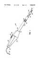
- FIG. 1is a perspective view of an electrosurgical device constructed in accordance with the principles of the present invention.
- FIGS. 2A and 2Bare side and top cross-sectional views, respectively, of an actuator handle for a surgical instrument constructed in accordance with the principles of the present invention.
- FIG. 3is a transverse cross-sectional view through the shaft coupled to the actuator handle of FIGS. 2A and 2B.
- FIGS. 4A and 4Bare perspective views of a distal end of the electrosurgical device of FIG. 1.
- FIGS. 5A and 5Bare front and top partial cross-sectional views, respectively, of the distal end of the electrosurgical device of FIG. 1.
- FIGS. 6A-6Dare front and top partial cross-sectional views of an alternative embodiment of the distal end of the electrosurgical device of FIG. 1, showing the paddle element in a retracted position and an extended position.
- FIGS. 7A and 7Bare front and top partial cross-sectional views, respectively, of a further alternative embodiment of the distal end of the electrosurgical device of FIG. 1.
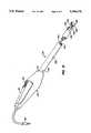
- FIG. 8is a perspective view of a fascia cutter utilizing an actuator handle constructed in accordance with the principles of the present invention.
- FIG. 9is a side cross-sectional view of a further embodiment of an actuator handle constructed in accordance with the principles of the present invention.
- FIG. 10is a partial side cross sectional view of yet another embodiment of an actuator handle constructed in accordance with the principles of the present invention.
- FIG. 11Ais a side cross-sectional view of a further embodiment of an actuator handle in a surgical scissor instrument in accordance with principles of the present invention.
- FIGS. 11B-11Care side cross-sectional views of a distal end of the scissor instrument of FIG. 11A.
- FIGS. 12A-12Care front elevational views illustrating the use of the electrosurgical device of FIG. 1 in a body cavity according to the principles of the method of the present invention.
- the present inventionprovides an actuator handle useful in connection with a variety of surgical instruments, with particular usefulness in LIS instruments. While the handle will be described in connection with electrosurgical devices for cauterizing and cutting tissue, fascia cutting instruments for enlarging a penetration through the fascial layer as well as surgical scissors, it will be understood that the actuator handle of the present invention may be adapted for use in a variety of both LIS and conventional surgical instruments which utilize a handle for gripping and manipulation by the surgeon and an actuator for selectively actuating the movable components in such devices.
- the actuator handle of the inventionis ergonomically designed for maximum device control, comfort and convenience.
- the actuator handlehas a streamlined design, having a tubular structure which is axially aligned with the elongate shafts typical of LIS instruments, without lateral protrusions which may interfere with personnel or equipment in the vicinity.
- the actuator handleutilizes an actuation lever axially aligned and nested within the handle housing which is easily actuated in various hand positions, eliminating the need for frequent changes of hand position.
- Particularly usefulis the locking feature of the actuator handle, wherein the actuation lever may be locked in position so that the moving components of the device, for example, an electrosurgical paddle element, will be maintained in an extended position. In this way, the instruments may be used in two or more configurations which do not require the surgeon to maintain pressure on the actuation lever.
- the actuator handlefurther provides electrical connection between the electrodes of an electrosurgical device and an electrosurgical generator.
- electrosurgical device 20has an actuator handle 22 having a distal end 24 and a proximal end 26.
- the handlehas an opening or aperture 28 on a lateral side in which is disposed a pivotable lever 30.
- Lever 30has a thumb switch 32 slidably disposed on a lateral surface of the lever.
- Actuator handle 22further includes pigtail connector 34 suitable for connection to an electrosurgical generator.
- An elongate shaft 36has a proximal end 38 coupled to the distal end 24 of actuator handle 22.
- a surgical hook 42is secured to distal end 40 of shaft 36.
- Shaft 36further includes an axial lumen 44 extending from the proximal end to the distal end of the shaft.
- a paddle element 46is slidably disposed in the axial lumen.
- Paddle element 46is fixed to the end of an actuator shaft 48 slidably disposed in axial lumen 44 and connected to a linkage rod 50 extending through axial lumen 44 into actuator handle 22.
- actuator handle 22comprises a housing 52, which may be formed from an electrically insulating material, such as acrylonitrile-butadiene-styrene (ABS), polycarbonate, Delrin® (an acetyl resin), or the like.
- Housing 52will have an elongate tubular construction, with round, partially round, rectangular or other cross-sectional shape suitable for gripping with a single hand.
- Tubular housing 52will define an open interior 54 generally aligned with the axial lumen 44 of shaft 36.
- Aperture 28will be formed on a lateral side of housing 52 and will have an axially aligned slot 56 which opens into interior 54 of the housing.
- Lever 30will be axially disposed in slot 56 with a lateral longitudinal portion of the lever exposed in aperture 28.
- a proximal end 58 of the leverwill be pivotally coupled to housing 52 by means of a pin 60.
- the distal end 66 of lever 30is pivotable about an axis perpendicular to the axial direction (defined by shaft 36) from an outward position to an inward position (shown in phantom) in the interior of housing 52.
- cylindrical heads 62extend outward from the sides of lever 30 and reside in guide channels 64 in the sidewalls of housing 52. The inward and outward movement of lever 30 is thereby limited by the engagement of heads 62 against the ends of channel 64.
- Lever 30has an open interior 70 and a vertical slot 72 along its distal side.
- a bellcrank 74is pivotally mounted in the interior of housing 52 distally of lever 30 by means of a pin 76.
- Bellcrank 74is generally triangular and pivots about pin 76 which extends through a first of the points of the bellcrank.
- bellcrank 74has a rounded contact surface 78 extending through slot 72 in the lever which slides against an interior surface 80 of lever 30.
- a third point 82 of bellcrank 74has a transverse bore through which the proximal end of linkage rod 50 extends.
- linkage rod 50will comprise a flexible rod of stainless steel or the like, which is laterally deflectable while having sufficient axial rigidity to actuate paddle element 46 at the distal end of the shaft.
- contact surface 78is engaged by interior surface 80 of the lever, rotating the bellcrank about pin 76 and translating linkage rod 50 axially through shaft 36.
- the proximal end of linkage rod 50is formed in a J or L shape to provide clearance for the bellcrank and to attain a transverse orientation to extend through transverse bore 82 in the bellcrank.
- a torsion spring 84is further provided about pin 76 to urge bellcrank 74 in a counterclockwise direction, biasing lever 30 in an outward position.
- the inventionfurther includes means for locking lever 30 in the inward position, which, in an exemplary embodiment, comprises a thumb switch 32 slidably mounted to lever 30 near the distal end 66 thereof.
- Thumb switch 32includes a surface contour 86 configured for engagement by the thumb. Usually, the surface contour will have transverse grooves or ridges to facilitate non-slip engagement.
- An extension portion 88extends distally from surface contour 86.
- the thumb switchfurther includes a sliding retainer portion 90 which resides in a slot 92 disposed axially through the lateral sidewall of lever 30. Thumb switch 32 is thereby configured to slide axially along lever 30 with retainer portion 90 sliding in slot 92.
- thumb switch 32may be moved distally so that extension portion 88 is received in a slot or aperture 94 in a distal portion of the housing, locking the lever in the inward position.
- linkage rod 50will comprise an electrically conductive material and will be connected at its proximal end to an electrical coupling 96 in housing 52. Electrical coupling 96 will be connected by means of a wire 97 to pigtail connector 34, for connection to an electrosurgical generator.
- actuator handle 22will include sealing means 98 for gaseously sealing the proximal end of axial lumen 44 in shaft 36.
- sealing means 98will comprise a cylindrical polymeric seal of a material such as silicone disposed near the proximal end of shaft 36 about linkage 50.
- Seal 98has an axial bore 101 through which linkage rod 50 may extend in sealable contact with the interior of the seal. In this way, seal 98 provides a gas-tight seal in the proximal end of the shaft, preventing leakage of insufflation gas through the axial lumen into the handle.
- Shaft 36will be mounted to actuator handle 22 by means of a collar assembly 102 disposed in a distal aperture 104 in housing 52.
- Collar assembly 102will preferably comprise a pair of split halves 103 each having an inward extending protrusion 105 which extends through one of a pair of transverse holes in shaft 36.
- collar 102will be solvent bonded to the housing within aperture 104, securing shaft 36 to the handle.
- pigtail connector 34will include a 3/32 inch diameter plug connector of standard configuration. It will be connected to commercially available electrosurgical power supplies such as those available from vendors such as Valley Lab, Inc. (A Pfizer Company), Boulder, Colo.; Aspen Labs, Inc. (A Conmead Company), Inglewood, Colo.; Birtcher Corp., Irvine, Calif.; and Bard Electromedical Systems, Inc., Inglewood, Colo.
- vendorssuch as Valley Lab, Inc. (A Pfizer Company), Boulder, Colo.; Aspen Labs, Inc. (A Conmead Company), Inglewood, Colo.; Birtcher Corp., Irvine, Calif.; and Bard Electromedical Systems, Inc., Inglewood, Colo.
- shaft 36will preferably comprise rigid, electrically conductive tubing 106, covered by an electrically insulating sleeve or cover 108.
- tubing 106will be surgical stainless steel
- insulating sleeve 108will be a polymeric material such as polyethylene.
- the dimensions of the shaft 36are not critical, but the diameter will usually be sufficiently small to allow for passage through a conventional cannula, usually being 5 mm or less in diameter.
- the shaftwill be sufficiently long to permit access by the distal tip to any desired location in the body, typically having a length in the range from about 25 cm to 38 cm.
- Surgical hook 42is composed of an electrically conductive material such as surgical stainless steel and is secured to the distal end of tubing 106.
- a paddle element 46is secured to actuator shaft 48 and may be axially reciprocated relative to surgical hook 42.
- Actuator shaft 48, linkage 50, as well as paddle element 46will also be electrically conductive, typically being stainless steel.
- Actuator shaft 48will preferably be in sliding engagement with tubing 106 in axial lumen 44, and paddle element 46 in sliding engagement with the hook 42, to provide electrical connection therebetween. In this way, electrical current delivered through linkage 50 will be conducted to paddle element 46 as well as hook 42.
- a single paddle elementis disposed adjacent a flat lateral face 110 of hook 42.
- Paddle element 46has a flat surface 111 disposed to slide against face 110. In this way, paddle element 46 may be shifted from a retracted position, shown in FIG. 4A, to an extended position, shown in FIG. 4B, by actuating lever 30 on actuator handle 22.
- Axial translation of paddle element 46 past surgical hook 42has several advantages. First, a leading edge 112 of paddle element will cooperate with an inner edge 114 of hook 42 to provide a shearing action as the paddle element is moved forward. Thus, when tissue or other body structure is held within hook 42, the shearing action of the paddle 46 may enhance dissection afforded by the electric current. Additionally, the motion of the paddle element 46 past the surgical hook 42 will be able to clean char and other tissue from the hook which may adhere to the hook during use.
- FIGS. 6A-6Dillustrate an alternative embodiment of paddle element 46 in the electrosurgical device of the present invention.
- paddle element 46comprises a forked end having a pair of parallel plates 116 each having a flat surface 118 which slides against flat faces 120 on either side of hook 42.
- Such a configurationprovides a double shearing action on a body structure received in hook 42 and further serves to apply balanced forces to the tissue structure on either side of hook 42 for effective tissue dissection.
- paddle element 46is axially aligned with hook 42 and slides in an axial channel 122 in the hook.
- Channel 122will preferably extend into the distal J-shaped portion 124 of the hook to permit leading edge 112 of the paddle element to extend at least partially into the channel in distal portion 124.
- paddle element 46enhances tissue dissection by urging the tissue within hook 42 against the distal portion 124 of the hook and penetrating leading edge 112 through the tissue.
- FIG. 8illustrates a further embodiment of the present invention wherein actuator handle 22 is incorporated in a fascia cutting instrument like that described in co-pending application Ser. No. 07/757,170, assigned to the assignee of the present invention, the complete disclosure of which has been incorporated herein by reference.
- Fascia cutting instrument 130includes an elongate shaft 132 attached at its proximal end 134 to the distal end 24 of handle 22.
- a slotted head 138is secured to distal end 136 of shaft 132. Head 138 defines a transverse slot 140.
- Shaft 132has an axial lumen 142 in which a linkage 144 is slidably disposed. The proximal end of linkage 144 will be coupled to bellcrank 74 in handle 22.
- linkage 144is connected to the proximal end of a blade 146 which is slidable in an axial channel 148 in head 138. In this way, actuation of lever 30 in handle 22 translates linkage 144 to reciprocate blade 146 across slot 140.
- Blade 146has a tapered cutting edge 150 along its distal end.
- blade 146, and linkage 144will be an electrically conductive material such as stainless steel, and will be electrically coupled to pigtail connector 34 in handle 22.
- Connector 34may be connected to an electrosurgical generator to deliver electric current through linkage 144 to blade 146 to enhance tissue dissection.
- lever 30will preferably be biased in an outward position so that blade 146 is retracted within shaft 132 when lever 30 is in the outward position.
- the fascia cutting device of FIG. 8will be positioned through a penetration in the fascia transversalis, and slot 140 will be positioned to receive a portion of the fascial layer.
- Blade 146may then be translated axially by actuating lever 30 to sever the fascial layer, enlarging the penetration.
- Electric currentmay be delivered from an electrical generator through connector 34 to blade 146 to enhance cutting.
- FIG. 9illustrates yet another embodiment of the actuator handle of the invention.
- actuator handle 22includes an aspiration/agent delivery port 154 for attachment of a suction device to aspirate the treatment site, or for attachment of an agent delivery mechanism, such as syringe or pump, to deliver a therapeutic agent or other fluid to the treatment site through axial lumen 44.
- Port 154will preferably comprise a lure fitting 156 having a passage 158 in fluid connection with an interior chamber 160 defined by an annular wall 162 formed in housing 52.
- the proximal end of shaft 36is disposed in chamber 160, and linkage 50 extends proximally through the chamber into the interior of the handle.
- a cylindrical seal 164seals the proximal end of chamber 160 about linkage 50 to prevent leakage of fluid or insufflation gas into the handle.
- aspiration of the treatment sitemay be accomplished by applying suction through passage 158, which will draw fluid through an opening at the distal end of shaft 36 (not shown) and proximally through axial lumen 44.
- a therapeutic agent or other fluidmay be delivered to the treatment site by delivering the agent or fluid into passage 158, from which it will flow through axial lumen 44 and an opening (not shown) at the distal end of shaft 36.
- FIG. 10illustrates an alternative embodiment of the lever locking means of the actuator handle.
- the lever locking meanscomprises a ratchet mechanism 166 on bellcrank 74.
- Ratchet mechanism 166includes a plurality of teeth 168 on bellcrank 74, and a pall 170 for engaging teeth 168.
- Pall 170is biased in a counter clockwise direction by tension spring 172, which urges the pall against a stop 174 on housing 52. In this way, inward movement of lever 30 rotates bellcrank 74 in a counter clockwise direction such that teeth 168 are successively engaged by pall 170.
- a release button 176is pressed, rotating pall 170 in a clockwise direction to disengage the pall from teeth 168, permitting clockwise rotation of bellcrank 74 under the force of torsion spring 84.
- FIGS. 11A-11Cillustrate a further embodiment of a surgical instrument incorporating the actuator handle of the present invention.
- the surgical instrumentcomprises surgical scissors, including actuator handle 182 at the proximal end of the device, shaft 184 secured to actuator handle 182, and, as shown is FIGS. 11B-11C, reciprocating blades 186 coupled to the distal end of shaft 184.
- a linkage 188is coupled to blades 186 and extends through an axial lumen 190 in shaft 184 to actuator handle 182.
- the proximal end of linkage 188is coupled to lever 192 in handle 182.
- Actuator handle 182is substantially the same as that described above in connection with FIGS.
- the coupling meanscomprises, in an exemplary embodiment, a bellcrank 194 which is pinned to handle housing 196 at pivot point 198. Bellcrank 194 slidably engages interior surface 200 of lever 192 along a curved contact surface 202. The proximal end of linkage rod 188 is coupled to bellcrank 194 at point 204. In this way, inward motion of lever 192 rotates bellcrank 194 in a counter-clockwise direction about pivot point 198, drawing linkage rod 188 in a proximal direction.
- blades 186are pivotally coupled together by a pin 206 which is secured to the distal end of shaft 184.
- Blades 186have sharpened inner edges 207 and slide in shearing action against each other when the blades are closed.
- Each bladehas an inclined slot 208 near its proximal end which overlap so as to receive a distal end 210 of linkage 188 through both slots. In this way, when linkage rod 188 is moved proximally, the movement of distal end 210 through slots 208 causes blades 186 to pivot toward each other into the position shown in FIG. 11C.
- blades 186 and linkage rod 188will be an electrically conductive material such as stainless steel.
- the proximal end of linkage rod 188is coupled to electrical coupling 212 and wire 214, which are coupled to pigtail connector 216 for connection to an electro-surgical generator.
- Shaft 184is covered with an electrically insulating sleeve 217 to prevent conduction of current to tissue through the shaft.
- lever 192may be locked in an inward position using a thumb switch 218 or other locking means as in previous embodiments.
- blades 186With lever 192 in a fully inward position, blades 186 will preferably be in a closed configuration as in FIG. 11C. In such a configuration, the blades have a profile sufficiently small for insertion through a trocar sleeve or other cannula.
- the devicemay be manipulated in the body cavity without sharp edges 207 exposed, to avoid any risk of injury.
- blades 186may be locked in the closed configuration for use as a monopolar electrode for cauterization or dissection.
- FIGS. 12A-12CThe method of the present invention will be described with reference to FIGS. 12A-12C. The method will be described in connection with the electrosurgical device of FIGS. 1-7, however, it will be understood that the principles of the method of the invention may be applied to techniques using a variety of surgical instruments, including the fascia cutter of FIG. 8 as well as a variety of other LIS and conventional surgical instruments.
- the electrosurgical device 20will be introduced through a trocar sleeve or other cannula 222 which is positioned percutaneously to facilitate introduction of instruments through a sealed passage into a body cavity C.
- the body cavitywill comprise the peritoneal cavity, in thoracoscopy the thorax, in pelviscopy the pelvis, and so on.
- the body cavity Cwill be insufflated using an insufflation gas, commonly carbon dioxide, to enlarge the cavity for enhanced visualization and access.
- Cannula 222will permit introduction of surgical instruments through a sealed passage which prevents leakage of insufflation gas from the body cavity.
- Electrosurgical device 20will be positioned through cannula 222 with the surgical hook 42 near the body structure S desired to be dissected, cauterized or manipulated.
- the surgeonwill grasp handle 22 to manipulate instrument 20 axially and rotationally so as to engage body structure S within hook 42.
- an electrosurgical generator Gmay be connected to connector 34 so as to deliver electric current to hook 42.
- the electric currentwill be passed from hook 42 to body structure S to cauterize, dissect or otherwise affect the body structure.
- paddle element 46may be extended from its retracted position in shaft 36 by pivoting lever 30 inward toward handle 22. This will cause paddle element 46 to be translated distally, sliding against hook 42. The shearing action of paddle element 46 against hook 42 will enhance dissection of body structure S. Electrical energy may also be delivered from electrosurgical generator G through paddle element 46, further enhancing dissection of the body structure. As described above, axial translation of paddle element 46 serves the additional purpose of removing char or other debris from hook 42.
- FIG. 12Cillustrates the paddle element 46 in a fully extended position.
- thumb switch 32may be slid distally into aperture 94 within handle 22 so as to lock lever 30 in position.
- paddle element 46will remain in the distally extended position while the user is free to release pressure on lever 30.
- the paddle elementthereby provides a wide, paddle-shaped monopolar electrode which can be used for various purposes in body cavity C, such as cauterization or dissection.
- the presence of paddle element 46 adjacent hook 42further eliminates the risk of unintentionally engaging a body structure in the hook as electrosurgical device 20 is manipulated or withdrawn from the body cavity.
- actuator handle of the present inventionhas been described in connection with electrosurgical devices fascia cutting instruments and surgical scissors, it will be understood that the actuator handle will be useful in connection with any of a variety of LIS and conventional surgical instruments which utilize movable components selectively actuated from a proximal end of the device.
- Exemplary instruments into which the actuator handle of the present invention may be incorporatedinclude graspers, retractors, needle holders and the like.
Landscapes
- Health & Medical Sciences (AREA)
- Surgery (AREA)
- Life Sciences & Earth Sciences (AREA)
- Biomedical Technology (AREA)
- Nuclear Medicine, Radiotherapy & Molecular Imaging (AREA)
- Engineering & Computer Science (AREA)
- Ophthalmology & Optometry (AREA)
- Heart & Thoracic Surgery (AREA)
- Medical Informatics (AREA)
- Molecular Biology (AREA)
- Animal Behavior & Ethology (AREA)
- General Health & Medical Sciences (AREA)
- Public Health (AREA)
- Veterinary Medicine (AREA)
- Surgical Instruments (AREA)
Abstract
Description
Claims (31)
Priority Applications (3)
| Application Number | Priority Date | Filing Date | Title |
|---|---|---|---|
| US08/042,329US5366476A (en) | 1993-04-02 | 1993-04-02 | Handle for laparoscopic instrument |
| AU65238/94AAU6523894A (en) | 1993-04-02 | 1994-03-23 | Handle for laparoscopic instrument |
| PCT/US1994/003167WO1994022376A1 (en) | 1993-04-02 | 1994-03-23 | Handle for laparoscopic instrument |
Applications Claiming Priority (1)
| Application Number | Priority Date | Filing Date | Title |
|---|---|---|---|
| US08/042,329US5366476A (en) | 1993-04-02 | 1993-04-02 | Handle for laparoscopic instrument |
Related Child Applications (1)
| Application Number | Title | Priority Date | Filing Date |
|---|---|---|---|
| US29007937Continuation-In-Part | 1993-05-05 |
Publications (1)
| Publication Number | Publication Date |
|---|---|
| US5366476Atrue US5366476A (en) | 1994-11-22 |
Family
ID=21921271
Family Applications (1)
| Application Number | Title | Priority Date | Filing Date |
|---|---|---|---|
| US08/042,329Expired - Fee RelatedUS5366476A (en) | 1993-04-02 | 1993-04-02 | Handle for laparoscopic instrument |
Country Status (3)
| Country | Link |
|---|---|
| US (1) | US5366476A (en) |
| AU (1) | AU6523894A (en) |
| WO (1) | WO1994022376A1 (en) |
Cited By (77)
| Publication number | Priority date | Publication date | Assignee | Title |
|---|---|---|---|---|
| WO1996023542A1 (en)* | 1995-02-02 | 1996-08-08 | Advanced Cardiovascular Systems, Inc. | Catheters having separable reusable components |
| USD378611S (en)* | 1995-10-19 | 1997-03-25 | Ethicon Endo-Surgery, Inc. | Electrosurgical instrument |
| WO1997040759A1 (en)* | 1996-05-02 | 1997-11-06 | Applied Medical Resources Corporation | Wire-form electrosurgical instruments |
| US5766169A (en)* | 1994-06-13 | 1998-06-16 | Delma Elektro-Und Medizinische Apparatebau Gesellschaft Mbh | Medical multifunctional instrument for performing endoscopic operations |
| USD403767S (en)* | 1997-10-09 | 1999-01-05 | Ethicon Endo-Surgery, Inc. | In-line handle for a surgical instrument |
| US5893863A (en)* | 1989-12-05 | 1999-04-13 | Yoon; Inbae | Surgical instrument with jaws and movable internal hook member for use thereof |
| US5919202A (en)* | 1989-12-05 | 1999-07-06 | Yoon; Inbae | Surgical instrument with jaws and movable internal needle and method for use thereof |
| US5922001A (en)* | 1989-12-05 | 1999-07-13 | Yoon; Inbae | Surgical instrument with jaws and a movable internal blade member and method for use thereof |
| US5921983A (en)* | 1997-05-13 | 1999-07-13 | Shannon, Jr.; Malcolm L. | Electrosurgical device for uvulopalatoplasty |
| US5922002A (en)* | 1989-12-05 | 1999-07-13 | Yoon; Inbae | Surgical instrument with jaws and movable internal biopsy device and method for use thereof |
| US5984939A (en) | 1989-12-05 | 1999-11-16 | Yoon; Inbae | Multifunctional grasping instrument with cutting member and operating channel for use in endoscopic and non-endoscopic procedures |
| US5984938A (en)* | 1989-12-05 | 1999-11-16 | Yoon; Inbae | Surgical instrument with jaws and movable internal scissors and method for use thereof |
| US6102907A (en)* | 1997-08-15 | 2000-08-15 | Somnus Medical Technologies, Inc. | Apparatus and device for use therein and method for ablation of tissue |
| US6113596A (en)* | 1996-12-30 | 2000-09-05 | Enable Medical Corporation | Combination monopolar-bipolar electrosurgical instrument system, instrument and cable |
| US6165175A (en)* | 1999-02-02 | 2000-12-26 | Ethicon Endo-Surgery, Inc. | RF bipolar mesentery takedown device including improved bipolar end effector |
| US6178354B1 (en) | 1998-12-02 | 2001-01-23 | C. R. Bard, Inc. | Internal mechanism for displacing a slidable electrode |
| US6221069B1 (en)* | 1996-11-26 | 2001-04-24 | S.L.T. Japan Co., Ltd. | Apparatus for medical treatment |
| US6245066B1 (en)* | 1996-05-11 | 2001-06-12 | C. R. Bard, Inc. | Ablation catheter |
| US6296640B1 (en)* | 1998-02-06 | 2001-10-02 | Ethicon Endo-Surgery, Inc. | RF bipolar end effector for use in electrosurgical instruments |
| US6358244B1 (en) | 1996-07-12 | 2002-03-19 | Endo Surgical Devices, Inc. | Endarterectomy surgical instrument and procedure |
| US6428538B1 (en) | 1995-10-20 | 2002-08-06 | United States Surgical Corporation | Apparatus and method for thermal treatment of body tissue |
| US6428503B1 (en) | 1999-01-19 | 2002-08-06 | Atc Technologies, Inc. | Surgical instrument for providing suction and irrigation |
| US6592582B2 (en)* | 2001-09-28 | 2003-07-15 | Ethicon, Inc. | Vessel harvesting retractor with electrosurgical plunger |
| US6613055B2 (en)* | 2001-09-21 | 2003-09-02 | Piergiacomi Sud - S.R.L. | Instrument for the implant of a surgical plate for osteosynthesis |
| US6673087B1 (en) | 2000-12-15 | 2004-01-06 | Origin Medsystems | Elongated surgical scissors |
| US6749609B1 (en) | 2002-02-05 | 2004-06-15 | Origin Medsystems, Inc. | Electrocautery scissors |
| US6773432B1 (en) | 1999-10-14 | 2004-08-10 | Applied Medical Resources Corporation | Electrosurgical snare |
| US6944914B2 (en) | 2001-10-24 | 2005-09-20 | Tillim Stephen L | Handle and forceps/tweezers and method and apparatus for designing the like |
| US6988295B2 (en) | 2001-10-24 | 2006-01-24 | Tillim Stephen L | Handle/grip and method for designing the like |
| US7010835B2 (en) | 2001-10-24 | 2006-03-14 | Tillim Stephen L | Parallel handle system and method for designing a parallel handle system |
| EP1435864A4 (en)* | 2001-09-28 | 2006-05-31 | Ethicon Inc | Surgical device for clamping, ligating and severing tissue |
| US7077856B2 (en) | 1999-06-02 | 2006-07-18 | Power Medical Interventions, Inc. | Electromechanical driver and remote surgical instrument attachment having computer assisted control capabilities |
| US7114642B2 (en) | 1999-07-12 | 2006-10-03 | Power Medical Interventions, Inc. | Expanding parallel jaw device for use with an electromechanical driver device |
| US20070032809A1 (en)* | 2001-01-18 | 2007-02-08 | Scimed Life Systems, Inc. | Steerable sphincterotome and methods for cannulation, papillotomy and sphincterotomy |
| US20080110047A1 (en)* | 2005-04-14 | 2008-05-15 | Nike, Inc. | Fluid-Filled Bladder for Footwear and Other Applications |
| US7537594B2 (en) | 2003-05-01 | 2009-05-26 | Covidien Ag | Suction coagulator with dissecting probe |
| US7695485B2 (en) | 2001-11-30 | 2010-04-13 | Power Medical Interventions, Llc | Surgical device |
| US20100152792A1 (en)* | 2001-07-16 | 2010-06-17 | Spinecore, Inc. | Insertion tool for use with intervertebral spacers |
| US7743960B2 (en) | 2002-06-14 | 2010-06-29 | Power Medical Interventions, Llc | Surgical device |
| US7803151B2 (en) | 2001-12-04 | 2010-09-28 | Power Medical Interventions, Llc | System and method for calibrating a surgical instrument |
| US7842035B2 (en) | 1999-02-01 | 2010-11-30 | Cytyc Corporation | Method and apparatus for tubal occlusion |
| US7867163B2 (en) | 1998-06-22 | 2011-01-11 | Maquet Cardiovascular Llc | Instrument and method for remotely manipulating a tissue structure |
| US7905880B2 (en) | 1997-06-05 | 2011-03-15 | Cytyc Corporation | Method and apparatus for tubal occlusion |
| US7918230B2 (en) | 2007-09-21 | 2011-04-05 | Tyco Healthcare Group Lp | Surgical device having a rotatable jaw portion |
| US7938842B1 (en) | 1998-08-12 | 2011-05-10 | Maquet Cardiovascular Llc | Tissue dissector apparatus |
| US7951071B2 (en) | 1999-06-02 | 2011-05-31 | Tyco Healthcare Group Lp | Moisture-detecting shaft for use with an electro-mechanical surgical device |
| US7963433B2 (en) | 2007-09-21 | 2011-06-21 | Tyco Healthcare Group Lp | Surgical device having multiple drivers |
| US7972265B1 (en) | 1998-06-22 | 2011-07-05 | Maquet Cardiovascular, Llc | Device and method for remote vessel ligation |
| US7981133B2 (en) | 1995-07-13 | 2011-07-19 | Maquet Cardiovascular, Llc | Tissue dissection method |
| US8016855B2 (en) | 2002-01-08 | 2011-09-13 | Tyco Healthcare Group Lp | Surgical device |
| US8025199B2 (en) | 2004-02-23 | 2011-09-27 | Tyco Healthcare Group Lp | Surgical cutting and stapling device |
| CN102429724A (en)* | 2011-10-17 | 2012-05-02 | 天津大学 | Monopole electric hook and monopole electric ablation tool for minimally invasive surgical robot |
| US8231619B2 (en) | 2010-01-22 | 2012-07-31 | Cytyc Corporation | Sterilization device and method |
| US8241210B2 (en) | 1998-06-22 | 2012-08-14 | Maquet Cardiovascular Llc | Vessel retractor |
| US8292888B2 (en) | 2001-04-20 | 2012-10-23 | Tyco Healthcare Group Lp | Bipolar or ultrasonic surgical device |
| USD680220S1 (en)* | 2012-01-12 | 2013-04-16 | Coviden IP | Slider handle for laparoscopic device |
| US20130190755A1 (en)* | 2012-01-23 | 2013-07-25 | Covidien Lp | Partitioned surgical instrument |
| US20130197515A1 (en)* | 2012-01-31 | 2013-08-01 | Boston Scientific Scimed, Inc. | Endoscopic instrument having a cutting tool |
| US8550086B2 (en) | 2010-05-04 | 2013-10-08 | Hologic, Inc. | Radiopaque implant |
| US8702727B1 (en) | 1999-02-01 | 2014-04-22 | Hologic, Inc. | Delivery catheter with implant ejection mechanism |
| US20140155891A1 (en)* | 2005-09-30 | 2014-06-05 | Covidien Lp | Flexible endoscopic catheter with ligasure |
| US20140214025A1 (en)* | 2013-01-25 | 2014-07-31 | Ethicon Endo-Surgery, Inc. | End effector with compliant clamping jaw |
| US20140277046A1 (en)* | 2013-03-15 | 2014-09-18 | Nico Corporation | Microsurgical instruments |
| US20140277038A1 (en)* | 2013-03-15 | 2014-09-18 | Kyphon Sarl | Retractable device to dissect and evacuate ligamentum flavum in lumber spinal stenosis |
| US20140276834A1 (en)* | 2013-03-15 | 2014-09-18 | DePuy Synthes Products, LLC | Methods and devices for removing a spinal disc |
| EP2789307A1 (en)* | 2013-04-08 | 2014-10-15 | Covidien LP | Surgical device for pediatric surgery |
| USD735327S1 (en)* | 2013-07-29 | 2015-07-28 | Cook Medical Technologies Llc | Transitional handle |
| US9113878B2 (en) | 2002-01-08 | 2015-08-25 | Covidien Lp | Pinion clip for right angle linear cutter |
| US9113939B2 (en) | 2009-10-09 | 2015-08-25 | Applied Medical Resources Corporation | Single port instruments |
| EP3187139A1 (en)* | 2013-12-31 | 2017-07-05 | Creo Medical Limited | Electrosurgical apparatus for delivering rf and/or microwave energy into biological tissue |
| US9896868B2 (en) | 2015-02-28 | 2018-02-20 | Ford Global Technologies, Llc | Vehicle hinge assembly and method of operating the same |
| US10149695B2 (en) | 2013-03-15 | 2018-12-11 | Nico Corporation | Microsurgical instruments |
| US10299770B2 (en) | 2006-06-01 | 2019-05-28 | Maquet Cardiovascular Llc | Endoscopic vessel harvesting system components |
| US20190262059A1 (en)* | 2016-07-28 | 2019-08-29 | Auxin Surgery | Electro-chemical surgical instrument |
| US10507012B2 (en) | 2000-11-17 | 2019-12-17 | Maquet Cardiovascular Llc | Vein harvesting system and method |
| US20200069363A1 (en)* | 2018-08-08 | 2020-03-05 | I.C. Medical, Inc. | Laparoscopic ultrapolar electrosurgery device |
| US12357286B2 (en)* | 2018-09-13 | 2025-07-15 | Medacta International Sa | Tool for the subcutaneous cutting of tendons |
Families Citing this family (1)
| Publication number | Priority date | Publication date | Assignee | Title |
|---|---|---|---|---|
| GB9803197D0 (en)* | 1998-02-17 | 1998-04-08 | Sterex Electrolysis Internatio | Electrolysis needle assembly |
Citations (14)
| Publication number | Priority date | Publication date | Assignee | Title |
|---|---|---|---|---|
| US4418692A (en)* | 1978-11-17 | 1983-12-06 | Guay Jean Louis | Device for treating living tissue with an electric current |
| US4672964A (en)* | 1986-02-21 | 1987-06-16 | Dee Robert N | Scalpel with universally adjustable blade |
| US4700702A (en)* | 1985-12-09 | 1987-10-20 | Tatiana Nilsson | Instrument for cutting tissues in surgery |
| US4760848A (en)* | 1986-11-03 | 1988-08-02 | Hasson Harrith M | Rotational surgical instrument |
| US4784137A (en)* | 1987-11-16 | 1988-11-15 | Kulik Yaroslav P | Surgical suturing instrument |
| US4976269A (en)* | 1989-10-26 | 1990-12-11 | Creative Research & Manufacturing | Tissue needle |
| US4991600A (en)* | 1987-04-15 | 1991-02-12 | Anchor Products Company | Sampling device |
| US5133735A (en)* | 1990-05-10 | 1992-07-28 | Symbiosis Corporation | Thumb-activated actuating member for imparting reciprocal motion to push rod of a disposable laparoscopic surgical instrument |
| US5141517A (en)* | 1990-01-16 | 1992-08-25 | Zimmer Inc. | Retractable instrument |
| US5147380A (en)* | 1991-10-03 | 1992-09-15 | Cordis Corporation | Biopsy forceps device having improved locking means |
| US5147373A (en)* | 1991-04-29 | 1992-09-15 | Ferzli George S | Laparoscopic instrument |
| US5176695A (en)* | 1991-07-08 | 1993-01-05 | Davinci Medical, Inc. | Surgical cutting means |
| US5184625A (en)* | 1992-04-16 | 1993-02-09 | Cordis Corporation | Biopsy forceps device having improved handle |
| US5190541A (en)* | 1990-10-17 | 1993-03-02 | Boston Scientific Corporation | Surgical instrument and method |
- 1993
- 1993-04-02USUS08/042,329patent/US5366476A/ennot_activeExpired - Fee Related
- 1994
- 1994-03-23AUAU65238/94Apatent/AU6523894A/ennot_activeAbandoned
- 1994-03-23WOPCT/US1994/003167patent/WO1994022376A1/enactiveApplication Filing
Patent Citations (14)
| Publication number | Priority date | Publication date | Assignee | Title |
|---|---|---|---|---|
| US4418692A (en)* | 1978-11-17 | 1983-12-06 | Guay Jean Louis | Device for treating living tissue with an electric current |
| US4700702A (en)* | 1985-12-09 | 1987-10-20 | Tatiana Nilsson | Instrument for cutting tissues in surgery |
| US4672964A (en)* | 1986-02-21 | 1987-06-16 | Dee Robert N | Scalpel with universally adjustable blade |
| US4760848A (en)* | 1986-11-03 | 1988-08-02 | Hasson Harrith M | Rotational surgical instrument |
| US4991600A (en)* | 1987-04-15 | 1991-02-12 | Anchor Products Company | Sampling device |
| US4784137A (en)* | 1987-11-16 | 1988-11-15 | Kulik Yaroslav P | Surgical suturing instrument |
| US4976269A (en)* | 1989-10-26 | 1990-12-11 | Creative Research & Manufacturing | Tissue needle |
| US5141517A (en)* | 1990-01-16 | 1992-08-25 | Zimmer Inc. | Retractable instrument |
| US5133735A (en)* | 1990-05-10 | 1992-07-28 | Symbiosis Corporation | Thumb-activated actuating member for imparting reciprocal motion to push rod of a disposable laparoscopic surgical instrument |
| US5190541A (en)* | 1990-10-17 | 1993-03-02 | Boston Scientific Corporation | Surgical instrument and method |
| US5147373A (en)* | 1991-04-29 | 1992-09-15 | Ferzli George S | Laparoscopic instrument |
| US5176695A (en)* | 1991-07-08 | 1993-01-05 | Davinci Medical, Inc. | Surgical cutting means |
| US5147380A (en)* | 1991-10-03 | 1992-09-15 | Cordis Corporation | Biopsy forceps device having improved locking means |
| US5184625A (en)* | 1992-04-16 | 1993-02-09 | Cordis Corporation | Biopsy forceps device having improved handle |
Non-Patent Citations (2)
| Title |
|---|
| Product Brochure "Laparomed Electrosurgical Device," Laparomed Corporation, ©Laparomed 1991. |
| Product Brochure Laparomed Electrosurgical Device, Laparomed Corporation, Laparomed 1991.* |
Cited By (151)
| Publication number | Priority date | Publication date | Assignee | Title |
|---|---|---|---|---|
| US5984939A (en) | 1989-12-05 | 1999-11-16 | Yoon; Inbae | Multifunctional grasping instrument with cutting member and operating channel for use in endoscopic and non-endoscopic procedures |
| US5893863A (en)* | 1989-12-05 | 1999-04-13 | Yoon; Inbae | Surgical instrument with jaws and movable internal hook member for use thereof |
| US5919202A (en)* | 1989-12-05 | 1999-07-06 | Yoon; Inbae | Surgical instrument with jaws and movable internal needle and method for use thereof |
| US5922001A (en)* | 1989-12-05 | 1999-07-13 | Yoon; Inbae | Surgical instrument with jaws and a movable internal blade member and method for use thereof |
| US5984938A (en)* | 1989-12-05 | 1999-11-16 | Yoon; Inbae | Surgical instrument with jaws and movable internal scissors and method for use thereof |
| US5922002A (en)* | 1989-12-05 | 1999-07-13 | Yoon; Inbae | Surgical instrument with jaws and movable internal biopsy device and method for use thereof |
| US5766169A (en)* | 1994-06-13 | 1998-06-16 | Delma Elektro-Und Medizinische Apparatebau Gesellschaft Mbh | Medical multifunctional instrument for performing endoscopic operations |
| WO1996023542A1 (en)* | 1995-02-02 | 1996-08-08 | Advanced Cardiovascular Systems, Inc. | Catheters having separable reusable components |
| US7981133B2 (en) | 1995-07-13 | 2011-07-19 | Maquet Cardiovascular, Llc | Tissue dissection method |
| USD378611S (en)* | 1995-10-19 | 1997-03-25 | Ethicon Endo-Surgery, Inc. | Electrosurgical instrument |
| US6428538B1 (en) | 1995-10-20 | 2002-08-06 | United States Surgical Corporation | Apparatus and method for thermal treatment of body tissue |
| WO1997040759A1 (en)* | 1996-05-02 | 1997-11-06 | Applied Medical Resources Corporation | Wire-form electrosurgical instruments |
| US6544263B2 (en) | 1996-05-11 | 2003-04-08 | C. R. Bard, Inc. | Ablation catheter |
| US6245066B1 (en)* | 1996-05-11 | 2001-06-12 | C. R. Bard, Inc. | Ablation catheter |
| US6358244B1 (en) | 1996-07-12 | 2002-03-19 | Endo Surgical Devices, Inc. | Endarterectomy surgical instrument and procedure |
| US6221069B1 (en)* | 1996-11-26 | 2001-04-24 | S.L.T. Japan Co., Ltd. | Apparatus for medical treatment |
| US6113596A (en)* | 1996-12-30 | 2000-09-05 | Enable Medical Corporation | Combination monopolar-bipolar electrosurgical instrument system, instrument and cable |
| US6193716B1 (en)* | 1997-05-13 | 2001-02-27 | Malcolm L. Shannon, Jr. | Electrosurgical device for uvulopalatoplasty |
| US5921983A (en)* | 1997-05-13 | 1999-07-13 | Shannon, Jr.; Malcolm L. | Electrosurgical device for uvulopalatoplasty |
| US7905880B2 (en) | 1997-06-05 | 2011-03-15 | Cytyc Corporation | Method and apparatus for tubal occlusion |
| US6102907A (en)* | 1997-08-15 | 2000-08-15 | Somnus Medical Technologies, Inc. | Apparatus and device for use therein and method for ablation of tissue |
| USD403767S (en)* | 1997-10-09 | 1999-01-05 | Ethicon Endo-Surgery, Inc. | In-line handle for a surgical instrument |
| US6296640B1 (en)* | 1998-02-06 | 2001-10-02 | Ethicon Endo-Surgery, Inc. | RF bipolar end effector for use in electrosurgical instruments |
| US6468275B1 (en)* | 1998-02-06 | 2002-10-22 | Ethicon Endo-Surgery, Inc. | RF bipolar mesentery takedown device including improved bipolar end effector |
| US6485490B2 (en) | 1998-02-06 | 2002-11-26 | Ethicon Endo-Surgery, Inc. | RF bipolar end effector for use in electrosurgical instruments |
| US7867163B2 (en) | 1998-06-22 | 2011-01-11 | Maquet Cardiovascular Llc | Instrument and method for remotely manipulating a tissue structure |
| US7972265B1 (en) | 1998-06-22 | 2011-07-05 | Maquet Cardiovascular, Llc | Device and method for remote vessel ligation |
| US8241210B2 (en) | 1998-06-22 | 2012-08-14 | Maquet Cardiovascular Llc | Vessel retractor |
| US9730782B2 (en) | 1998-08-12 | 2017-08-15 | Maquet Cardiovascular Llc | Vessel harvester |
| US9700398B2 (en) | 1998-08-12 | 2017-07-11 | Maquet Cardiovascular Llc | Vessel harvester |
| US8460331B2 (en) | 1998-08-12 | 2013-06-11 | Maquet Cardiovascular, Llc | Tissue dissector apparatus and method |
| US7938842B1 (en) | 1998-08-12 | 2011-05-10 | Maquet Cardiovascular Llc | Tissue dissector apparatus |
| US8986335B2 (en) | 1998-08-12 | 2015-03-24 | Maquet Cardiovascular Llc | Tissue dissector apparatus and method |
| US6178354B1 (en) | 1998-12-02 | 2001-01-23 | C. R. Bard, Inc. | Internal mechanism for displacing a slidable electrode |
| US6428503B1 (en) | 1999-01-19 | 2002-08-06 | Atc Technologies, Inc. | Surgical instrument for providing suction and irrigation |
| US8702727B1 (en) | 1999-02-01 | 2014-04-22 | Hologic, Inc. | Delivery catheter with implant ejection mechanism |
| US8226645B2 (en) | 1999-02-01 | 2012-07-24 | Cytyc Corporation | Apparatus for tubal occlusion |
| US7842035B2 (en) | 1999-02-01 | 2010-11-30 | Cytyc Corporation | Method and apparatus for tubal occlusion |
| US6165175A (en)* | 1999-02-02 | 2000-12-26 | Ethicon Endo-Surgery, Inc. | RF bipolar mesentery takedown device including improved bipolar end effector |
| US8690913B2 (en) | 1999-06-02 | 2014-04-08 | Covidien Lp | Electromechanical drive and remote surgical instrument attachment having computer assisted control capabilities |
| US9662109B2 (en) | 1999-06-02 | 2017-05-30 | Covidien Lp | Electromechanical drive and remote surgical instrument attachment having computer assisted control capabilities |
| US8628467B2 (en) | 1999-06-02 | 2014-01-14 | Covidien Lp | Moisture-detecting shaft for use with an electro-mechanical surgical device |
| US9247940B2 (en) | 1999-06-02 | 2016-02-02 | Covidien Lp | Surgical cutting and stapling device |
| US9662514B2 (en) | 1999-06-02 | 2017-05-30 | Covidien Lp | Bipolar or ultrasonic surgical device |
| US9241716B2 (en) | 1999-06-02 | 2016-01-26 | Covidien Lp | Electromechanical drive and remote surgical instrument attachment having computer assisted control capabilities |
| US8016858B2 (en) | 1999-06-02 | 2011-09-13 | Tyco Healthcare Group Ip | Electromechanical driver and remote surgical instrument attachment having computer assisted control capabilities |
| US7077856B2 (en) | 1999-06-02 | 2006-07-18 | Power Medical Interventions, Inc. | Electromechanical driver and remote surgical instrument attachment having computer assisted control capabilities |
| US7758613B2 (en) | 1999-06-02 | 2010-07-20 | Power Medical Interventions, Llc | Electromechanical driver and remote surgical instrument attachment having computer assisted control capabilities |
| US9782172B2 (en) | 1999-06-02 | 2017-10-10 | Covidien Lp | Electromechanical drive and remote surgical instrument attachment having computer assisted control capabilities |
| US9078654B2 (en) | 1999-06-02 | 2015-07-14 | Covidien Lp | Surgical device |
| US7951071B2 (en) | 1999-06-02 | 2011-05-31 | Tyco Healthcare Group Lp | Moisture-detecting shaft for use with an electro-mechanical surgical device |
| US10335143B2 (en) | 1999-06-02 | 2019-07-02 | Covidien Lp | Surgical cutting and stapling device |
| US9033868B2 (en) | 1999-06-02 | 2015-05-19 | Covidien Lp | Couplings for interconnecting components of an electro-mechanical surgical device |
| US7114642B2 (en) | 1999-07-12 | 2006-10-03 | Power Medical Interventions, Inc. | Expanding parallel jaw device for use with an electromechanical driver device |
| US8459523B2 (en) | 1999-07-12 | 2013-06-11 | Covidien Lp | Expanding parallel jaw device for use with an electromechanical driver device |
| US7845538B2 (en) | 1999-07-12 | 2010-12-07 | Power Medical Interventions, Llc | Expanding parallel jaw device for use with an electromechanical driver device |
| US7537602B2 (en) | 1999-07-12 | 2009-05-26 | Power Medical Interventions, Inc. | Expanding parallel jaw device for use with an electromechanical driver device |
| US8186559B1 (en) | 1999-07-12 | 2012-05-29 | Tyco Healthcare Group Lp | Expanding parallel jaw device for use with an electromechanical driver device |
| US8118208B2 (en) | 1999-07-12 | 2012-02-21 | Tyco Healthcare Group Lp | Expanding parallel jaw device for use with an electromechanical driver device |
| US8056791B2 (en) | 1999-07-12 | 2011-11-15 | Tyco Healthcare Group Lp | Expanding parallel jaw device for use with an electromechanical driver device |
| US6773432B1 (en) | 1999-10-14 | 2004-08-10 | Applied Medical Resources Corporation | Electrosurgical snare |
| US10507012B2 (en) | 2000-11-17 | 2019-12-17 | Maquet Cardiovascular Llc | Vein harvesting system and method |
| US6673087B1 (en) | 2000-12-15 | 2004-01-06 | Origin Medsystems | Elongated surgical scissors |
| US20070032809A1 (en)* | 2001-01-18 | 2007-02-08 | Scimed Life Systems, Inc. | Steerable sphincterotome and methods for cannulation, papillotomy and sphincterotomy |
| US7947056B2 (en)* | 2001-01-18 | 2011-05-24 | Boston Scientific Scimed, Inc. | Steerable sphincterotome and methods for cannulation, papillotomy and sphincterotomy |
| US8292888B2 (en) | 2001-04-20 | 2012-10-23 | Tyco Healthcare Group Lp | Bipolar or ultrasonic surgical device |
| US8523890B2 (en) | 2001-04-20 | 2013-09-03 | Covidien Lp | Bipolar or ultrasonic surgical device |
| US8845665B2 (en) | 2001-04-20 | 2014-09-30 | Covidien Lp | Bipolar or ultrasonic surgical device |
| US20100152792A1 (en)* | 2001-07-16 | 2010-06-17 | Spinecore, Inc. | Insertion tool for use with intervertebral spacers |
| US8348958B2 (en)* | 2001-07-16 | 2013-01-08 | Spinecore, Inc. | Insertion tool for use with intervertebral spacers |
| US6613055B2 (en)* | 2001-09-21 | 2003-09-02 | Piergiacomi Sud - S.R.L. | Instrument for the implant of a surgical plate for osteosynthesis |
| EP1435864A4 (en)* | 2001-09-28 | 2006-05-31 | Ethicon Inc | Surgical device for clamping, ligating and severing tissue |
| US6592582B2 (en)* | 2001-09-28 | 2003-07-15 | Ethicon, Inc. | Vessel harvesting retractor with electrosurgical plunger |
| US20040097921A1 (en)* | 2001-09-28 | 2004-05-20 | Ethicon, Inc. | Vessel harvesting retractor with electrosurgical plunger |
| US6944914B2 (en) | 2001-10-24 | 2005-09-20 | Tillim Stephen L | Handle and forceps/tweezers and method and apparatus for designing the like |
| US6988295B2 (en) | 2001-10-24 | 2006-01-24 | Tillim Stephen L | Handle/grip and method for designing the like |
| US7506409B2 (en) | 2001-10-24 | 2009-03-24 | Tillim Stephen L | Handle/grip and method for designing the like |
| US7010835B2 (en) | 2001-10-24 | 2006-03-14 | Tillim Stephen L | Parallel handle system and method for designing a parallel handle system |
| US7695485B2 (en) | 2001-11-30 | 2010-04-13 | Power Medical Interventions, Llc | Surgical device |
| US8021373B2 (en) | 2001-11-30 | 2011-09-20 | Tyco Healthcare Group Lp | Surgical device |
| US8512359B2 (en) | 2001-11-30 | 2013-08-20 | Covidien Lp | Surgical device |
| US8740932B2 (en) | 2001-11-30 | 2014-06-03 | Covidien Lp | Surgical device |
| US10758225B2 (en) | 2001-12-04 | 2020-09-01 | Covidien Lp | System and method for calibrating a surgical instrument |
| US9743927B2 (en) | 2001-12-04 | 2017-08-29 | Covidien Lp | System and method for calibrating a surgical instrument |
| US7803151B2 (en) | 2001-12-04 | 2010-09-28 | Power Medical Interventions, Llc | System and method for calibrating a surgical instrument |
| US8858589B2 (en) | 2002-01-08 | 2014-10-14 | Covidien Lp | Surgical device |
| US8518074B2 (en) | 2002-01-08 | 2013-08-27 | Covidien Lp | Surgical device |
| US8016855B2 (en) | 2002-01-08 | 2011-09-13 | Tyco Healthcare Group Lp | Surgical device |
| US9113878B2 (en) | 2002-01-08 | 2015-08-25 | Covidien Lp | Pinion clip for right angle linear cutter |
| US7344536B1 (en) | 2002-02-05 | 2008-03-18 | Origin Medsystems, Inc. | Electrocautery surgical scissors |
| US6749609B1 (en) | 2002-02-05 | 2004-06-15 | Origin Medsystems, Inc. | Electrocautery scissors |
| US8056786B2 (en) | 2002-06-14 | 2011-11-15 | Tyco Healthcare Group Lp | Surgical device |
| US9861362B2 (en) | 2002-06-14 | 2018-01-09 | Covidien Lp | Surgical device |
| US8540733B2 (en) | 2002-06-14 | 2013-09-24 | Covidien Lp | Surgical method and device having a first jaw and a second jaw in opposed correspondence for clamping, cutting, and stapling tissue |
| US7743960B2 (en) | 2002-06-14 | 2010-06-29 | Power Medical Interventions, Llc | Surgical device |
| US7537594B2 (en) | 2003-05-01 | 2009-05-26 | Covidien Ag | Suction coagulator with dissecting probe |
| US8025199B2 (en) | 2004-02-23 | 2011-09-27 | Tyco Healthcare Group Lp | Surgical cutting and stapling device |
| US11219452B2 (en) | 2004-02-23 | 2022-01-11 | Covidien Lp | Surgical cutting and stapling device |
| US20080110047A1 (en)* | 2005-04-14 | 2008-05-15 | Nike, Inc. | Fluid-Filled Bladder for Footwear and Other Applications |
| US20140155891A1 (en)* | 2005-09-30 | 2014-06-05 | Covidien Lp | Flexible endoscopic catheter with ligasure |
| US9579145B2 (en)* | 2005-09-30 | 2017-02-28 | Covidien Ag | Flexible endoscopic catheter with ligasure |
| US10299770B2 (en) | 2006-06-01 | 2019-05-28 | Maquet Cardiovascular Llc | Endoscopic vessel harvesting system components |
| US11134835B2 (en) | 2006-06-01 | 2021-10-05 | Maquet Cardiovascular Llc | Endoscopic vessel harvesting system components |
| US11141055B2 (en) | 2006-06-01 | 2021-10-12 | Maquet Cardiovascular Llc | Endoscopic vessel harvesting system components |
| US8353440B2 (en) | 2007-09-21 | 2013-01-15 | Covidien Lp | Surgical device having a rotatable jaw portion |
| US10881397B2 (en) | 2007-09-21 | 2021-01-05 | Covidien Lp | Surgical device having a rotatable jaw portion |
| US9017371B2 (en) | 2007-09-21 | 2015-04-28 | Covidien Lp | Surgical device having multiple drivers |
| US10117651B2 (en) | 2007-09-21 | 2018-11-06 | Covidien Lp | Surgical device having a rotatable jaw portion |
| US7918230B2 (en) | 2007-09-21 | 2011-04-05 | Tyco Healthcare Group Lp | Surgical device having a rotatable jaw portion |
| US11317909B2 (en) | 2007-09-21 | 2022-05-03 | Covidien Lp | Surgical device having multiple drivers |
| US9204877B2 (en) | 2007-09-21 | 2015-12-08 | Covidien Lp | Surgical device having a rotatable jaw portion |
| US7963433B2 (en) | 2007-09-21 | 2011-06-21 | Tyco Healthcare Group Lp | Surgical device having multiple drivers |
| US7992758B2 (en) | 2007-09-21 | 2011-08-09 | Tyco Healthcare Group Lp | Surgical device having a rotatable jaw portion |
| US9282961B2 (en) | 2007-09-21 | 2016-03-15 | Covidien Lp | Surgical device having multiple drivers |
| US8752748B2 (en) | 2007-09-21 | 2014-06-17 | Covidien Lp | Surgical device having a rotatable jaw portion |
| US8342379B2 (en) | 2007-09-21 | 2013-01-01 | Covidien Lp | Surgical device having multiple drivers |
| US10420548B2 (en) | 2007-09-21 | 2019-09-24 | Covidien Lp | Surgical device having multiple drivers |
| US8272554B2 (en) | 2007-09-21 | 2012-09-25 | Tyco Healthcare Group Lp | Surgical device having multiple drivers |
| US10420576B2 (en) | 2009-10-09 | 2019-09-24 | Applied Medical Resources Corporation | Single port instruments |
| US11622783B2 (en) | 2009-10-09 | 2023-04-11 | Applied Medical Resources Corporation | Single port instruments |
| US9113939B2 (en) | 2009-10-09 | 2015-08-25 | Applied Medical Resources Corporation | Single port instruments |
| US8231619B2 (en) | 2010-01-22 | 2012-07-31 | Cytyc Corporation | Sterilization device and method |
| US8550086B2 (en) | 2010-05-04 | 2013-10-08 | Hologic, Inc. | Radiopaque implant |
| CN102429724A (en)* | 2011-10-17 | 2012-05-02 | 天津大学 | Monopole electric hook and monopole electric ablation tool for minimally invasive surgical robot |
| USD680220S1 (en)* | 2012-01-12 | 2013-04-16 | Coviden IP | Slider handle for laparoscopic device |
| US9918777B2 (en) | 2012-01-23 | 2018-03-20 | Covidien Lp | Partitioned surgical instrument |
| US9113897B2 (en)* | 2012-01-23 | 2015-08-25 | Covidien Lp | Partitioned surgical instrument |
| US11007000B2 (en) | 2012-01-23 | 2021-05-18 | Covidien Lp | Partitioned surgical instrument |
| US20130190755A1 (en)* | 2012-01-23 | 2013-07-25 | Covidien Lp | Partitioned surgical instrument |
| US20130197515A1 (en)* | 2012-01-31 | 2013-08-01 | Boston Scientific Scimed, Inc. | Endoscopic instrument having a cutting tool |
| US9149325B2 (en)* | 2013-01-25 | 2015-10-06 | Ethicon Endo-Surgery, Inc. | End effector with compliant clamping jaw |
| US20140214025A1 (en)* | 2013-01-25 | 2014-07-31 | Ethicon Endo-Surgery, Inc. | End effector with compliant clamping jaw |
| US20140277038A1 (en)* | 2013-03-15 | 2014-09-18 | Kyphon Sarl | Retractable device to dissect and evacuate ligamentum flavum in lumber spinal stenosis |
| US20160199200A1 (en)* | 2013-03-15 | 2016-07-14 | DePuy Synthes Products, Inc. | Methods and devices for removing a spinal disc |
| US10080572B2 (en)* | 2013-03-15 | 2018-09-25 | DePuy Synthes Products, Inc. | Methods and devices for removing a spinal disc |
| US10398458B2 (en)* | 2013-03-15 | 2019-09-03 | Nico Corporation | Microsurgical instruments |
| US10149695B2 (en) | 2013-03-15 | 2018-12-11 | Nico Corporation | Microsurgical instruments |
| US20140277046A1 (en)* | 2013-03-15 | 2014-09-18 | Nico Corporation | Microsurgical instruments |
| US20140276834A1 (en)* | 2013-03-15 | 2014-09-18 | DePuy Synthes Products, LLC | Methods and devices for removing a spinal disc |
| US9314254B2 (en)* | 2013-03-15 | 2016-04-19 | DePuy Synthes Products, Inc. | Methods and devices for removing a spinal disc |
| US9402648B2 (en)* | 2013-03-15 | 2016-08-02 | Kyphon SÀRL | Retractable device to dissect and evacuate ligamentum flavum in lumbar spinal stenosis |
| US10117665B2 (en) | 2013-03-15 | 2018-11-06 | Medtronic Holding Company Sàrl | Retractable device to dissect and evacuate ligamentum flavum in lumbar spinal stenosis |
| EP2789307A1 (en)* | 2013-04-08 | 2014-10-15 | Covidien LP | Surgical device for pediatric surgery |
| USD735327S1 (en)* | 2013-07-29 | 2015-07-28 | Cook Medical Technologies Llc | Transitional handle |
| EP3187139A1 (en)* | 2013-12-31 | 2017-07-05 | Creo Medical Limited | Electrosurgical apparatus for delivering rf and/or microwave energy into biological tissue |
| US9896868B2 (en) | 2015-02-28 | 2018-02-20 | Ford Global Technologies, Llc | Vehicle hinge assembly and method of operating the same |
| US11272974B2 (en)* | 2016-07-28 | 2022-03-15 | Auxin Surgery | Electro-chemical surgical instrument |
| US20190262059A1 (en)* | 2016-07-28 | 2019-08-29 | Auxin Surgery | Electro-chemical surgical instrument |
| US20200069363A1 (en)* | 2018-08-08 | 2020-03-05 | I.C. Medical, Inc. | Laparoscopic ultrapolar electrosurgery device |
| US12285204B2 (en) | 2018-08-08 | 2025-04-29 | I.C. Medical, Inc. | Laparoscopic ultrapolar electrosurgery device |
| US12357286B2 (en)* | 2018-09-13 | 2025-07-15 | Medacta International Sa | Tool for the subcutaneous cutting of tendons |
Also Published As
| Publication number | Publication date |
|---|---|
| AU6523894A (en) | 1994-10-24 |
| WO1994022376A1 (en) | 1994-10-13 |
Similar Documents
| Publication | Publication Date | Title |
|---|---|---|
| US5366476A (en) | Handle for laparoscopic instrument | |
| US5797939A (en) | Endoscopic scissors with longitudinal operating channel | |
| US5797958A (en) | Endoscopic grasping instrument with scissors | |
| US5984938A (en) | Surgical instrument with jaws and movable internal scissors and method for use thereof | |
| US6099550A (en) | Surgical instrument having jaws and an operating channel and method for use thereof | |
| US5922001A (en) | Surgical instrument with jaws and a movable internal blade member and method for use thereof | |
| US5919202A (en) | Surgical instrument with jaws and movable internal needle and method for use thereof | |
| US5922002A (en) | Surgical instrument with jaws and movable internal biopsy device and method for use thereof | |
| US5573535A (en) | Bipolar surgical instrument for coagulation and cutting | |
| US5984939A (en) | Multifunctional grasping instrument with cutting member and operating channel for use in endoscopic and non-endoscopic procedures | |
| US5190541A (en) | Surgical instrument and method | |
| AU710892B2 (en) | Multi functional instrument with interchangeable operating units for performing endoscopic procedures | |
| US5460629A (en) | Electrosurgical device and method | |
| US5893863A (en) | Surgical instrument with jaws and movable internal hook member for use thereof | |
| US5735849A (en) | Endoscopic forceps with thumb-slide lock release mechanism | |
| US7507232B1 (en) | Flexible electrosurgical electrode with manipulator | |
| US6358268B1 (en) | Surgical instrument | |
| US6387094B1 (en) | Medical instrument for dissecting tissue | |
| EP0536998B1 (en) | Monopolar electrosurgical device with irrigation and suction controls for endoscopic surgery | |
| US9585714B2 (en) | Surgical sealing and cutting apparatus | |
| CA2535467C (en) | Electrosurgical device | |
| US7033357B2 (en) | Apparatus and method for minimally invasive surgery using rotational cutting tool | |
| US20130053877A1 (en) | Multiple Function Surgical Instrument | |
| JP6463832B2 (en) | Needle scissor-type end effector and method of use | |
| EP0553282A1 (en) | Apparatus for stereotoxic surgery and method of control of the apparatus |
Legal Events
| Date | Code | Title | Description |
|---|---|---|---|
| AS | Assignment | Owner name:LAPAROMED CORPORATION, CALIFORNIA Free format text:ASSIGNMENT OF ASSIGNORS INTEREST.;ASSIGNOR:NODA, WAYNE A.;REEL/FRAME:006494/0927 Effective date:19930330 | |
| FEPP | Fee payment procedure | Free format text:PAYOR NUMBER ASSIGNED (ORIGINAL EVENT CODE: ASPN); ENTITY STATUS OF PATENT OWNER: LARGE ENTITY | |
| AS | Assignment | Owner name:ADVANCED SURGICAL, INC., NEW JERSEY Free format text:ASSIGNMENT OF ASSIGNORS INTEREST;ASSIGNOR:LAPAROMED CORPORATION;REEL/FRAME:008153/0605 Effective date:19960904 Owner name:UROHEALTH SYSTEMS, INC., CALIFORNIA Free format text:ASSIGNMENT OF ASSIGNORS INTEREST;ASSIGNOR:ADVANCED SURGICAL, INC.;REEL/FRAME:008153/0569 Effective date:19960903 | |
| FEPP | Fee payment procedure | Free format text:PAT HLDR NO LONGER CLAIMS SMALL ENT STAT AS SMALL BUSINESS (ORIGINAL EVENT CODE: LSM2); ENTITY STATUS OF PATENT OWNER: LARGE ENTITY | |
| AS | Assignment | Owner name:IMAGYN MEDICAL TECHNOLOGIES, INC., CALIFORNIA Free format text:CHANGE OF NAME;ASSIGNOR:UROHEALTH SYSTEMS, INC.;REEL/FRAME:008876/0078 Effective date:19970929 | |
| AS | Assignment | Owner name:BT COMMERCIAL CORPORATION, ILLINOIS Free format text:SECURITY AGREEMENT;ASSIGNOR:IMAGYN MEDICAL TECHNOLOGIES, INC.;REEL/FRAME:008886/0680 Effective date:19971230 | |
| AS | Assignment | Owner name:DACOMED INTERNATIONAL INC., MINNESOTA Free format text:RELEASE OF SECURITY INTEREST;ASSIGNOR:CREDIT AGRICOLE INDOSUEZ;REEL/FRAME:008920/0448 Effective date:19971219 Owner name:DACOMED CORPORATION, MINNESOTA Free format text:RELEASE OF SECURITY INTEREST;ASSIGNOR:CREDIT AGRICOLE INDOSUEZ;REEL/FRAME:008920/0448 Effective date:19971219 Owner name:UROHEALTH, INC., CALIFORNIA Free format text:RELEASE OF SECURITY INTEREST;ASSIGNOR:CREDIT AGRICOLE INDOSUEZ;REEL/FRAME:008920/0448 Effective date:19971219 Owner name:ALLSTATE MEDICAL PRODUCTS, INC., MINNESOTA Free format text:RELEASE OF SECURITY INTEREST;ASSIGNOR:CREDIT AGRICOLE INDOSUEZ;REEL/FRAME:008920/0448 Effective date:19971219 Owner name:UROHEALTH OF KENTUCKY, INC., KENTUCKY Free format text:RELEASE OF SECURITY INTEREST;ASSIGNOR:CREDIT AGRICOLE INDOSUEZ;REEL/FRAME:008920/0448 Effective date:19971219 Owner name:GATES PLASTICS, CALIFORNIA Free format text:RELEASE OF SECURITY INTEREST;ASSIGNOR:CREDIT AGRICOLE INDOSUEZ;REEL/FRAME:008920/0448 Effective date:19971219 | |
| FPAY | Fee payment | Year of fee payment:4 | |
| AS | Assignment | Owner name:BT COMMERCIAL CORPORATION, ILLINOIS Free format text:SECURITY AGREEMENT;ASSIGNOR:IMAGYN MEDICAL TECHNOLOGIES, INC.;REEL/FRAME:010444/0304 Effective date:19991029 | |
| AS | Assignment | Owner name:BT COMMERCIAL CORPORATION A DELAWARE CORPORATION, Free format text:SECURITY INTEREST;ASSIGNOR:IMAGYN MEDICAL TECHNOLOGIES, INC. A DELAWARE CORPORATION;REEL/FRAME:010437/0079 Effective date:19991029 | |
| REMI | Maintenance fee reminder mailed | ||
| LAPS | Lapse for failure to pay maintenance fees | ||
| STCH | Information on status: patent discontinuation | Free format text:PATENT EXPIRED DUE TO NONPAYMENT OF MAINTENANCE FEES UNDER 37 CFR 1.362 | |
| FP | Lapsed due to failure to pay maintenance fee | Effective date:20021122 |