US5365551A - Data communication transceiver using identification protocol - Google Patents
Data communication transceiver using identification protocolDownload PDFInfo
- Publication number
- US5365551A US5365551AUS07/990,918US99091892AUS5365551AUS 5365551 AUS5365551 AUS 5365551AUS 99091892 AUS99091892 AUS 99091892AUS 5365551 AUS5365551 AUS 5365551A
- Authority
- US
- United States
- Prior art keywords
- transceiver
- subset
- station
- signal
- responder
- Prior art date
- Legal status (The legal status is an assumption and is not a legal conclusion. Google has not performed a legal analysis and makes no representation as to the accuracy of the status listed.)
- Expired - Lifetime
Links
Images


Classifications
- G—PHYSICS
- G01—MEASURING; TESTING
- G01S—RADIO DIRECTION-FINDING; RADIO NAVIGATION; DETERMINING DISTANCE OR VELOCITY BY USE OF RADIO WAVES; LOCATING OR PRESENCE-DETECTING BY USE OF THE REFLECTION OR RERADIATION OF RADIO WAVES; ANALOGOUS ARRANGEMENTS USING OTHER WAVES
- G01S13/00—Systems using the reflection or reradiation of radio waves, e.g. radar systems; Analogous systems using reflection or reradiation of waves whose nature or wavelength is irrelevant or unspecified
- G01S13/74—Systems using reradiation of radio waves, e.g. secondary radar systems; Analogous systems
- G01S13/75—Systems using reradiation of radio waves, e.g. secondary radar systems; Analogous systems using transponders powered from received waves, e.g. using passive transponders, or using passive reflectors
- G01S13/751—Systems using reradiation of radio waves, e.g. secondary radar systems; Analogous systems using transponders powered from received waves, e.g. using passive transponders, or using passive reflectors wherein the responder or reflector radiates a coded signal
- G01S13/758—Systems using reradiation of radio waves, e.g. secondary radar systems; Analogous systems using transponders powered from received waves, e.g. using passive transponders, or using passive reflectors wherein the responder or reflector radiates a coded signal using a signal generator powered by the interrogation signal
- G—PHYSICS
- G01—MEASURING; TESTING
- G01S—RADIO DIRECTION-FINDING; RADIO NAVIGATION; DETERMINING DISTANCE OR VELOCITY BY USE OF RADIO WAVES; LOCATING OR PRESENCE-DETECTING BY USE OF THE REFLECTION OR RERADIATION OF RADIO WAVES; ANALOGOUS ARRANGEMENTS USING OTHER WAVES
- G01S13/00—Systems using the reflection or reradiation of radio waves, e.g. radar systems; Analogous systems using reflection or reradiation of waves whose nature or wavelength is irrelevant or unspecified
- G01S13/74—Systems using reradiation of radio waves, e.g. secondary radar systems; Analogous systems
- G01S13/76—Systems using reradiation of radio waves, e.g. secondary radar systems; Analogous systems wherein pulse-type signals are transmitted
- G01S13/765—Systems using reradiation of radio waves, e.g. secondary radar systems; Analogous systems wherein pulse-type signals are transmitted with exchange of information between interrogator and responder
- G—PHYSICS
- G01—MEASURING; TESTING
- G01S—RADIO DIRECTION-FINDING; RADIO NAVIGATION; DETERMINING DISTANCE OR VELOCITY BY USE OF RADIO WAVES; LOCATING OR PRESENCE-DETECTING BY USE OF THE REFLECTION OR RERADIATION OF RADIO WAVES; ANALOGOUS ARRANGEMENTS USING OTHER WAVES
- G01S13/00—Systems using the reflection or reradiation of radio waves, e.g. radar systems; Analogous systems using reflection or reradiation of waves whose nature or wavelength is irrelevant or unspecified
- G01S13/74—Systems using reradiation of radio waves, e.g. secondary radar systems; Analogous systems
- G01S13/76—Systems using reradiation of radio waves, e.g. secondary radar systems; Analogous systems wherein pulse-type signals are transmitted
- G01S13/767—Responders; Transponders
- G—PHYSICS
- G06—COMPUTING OR CALCULATING; COUNTING
- G06K—GRAPHICAL DATA READING; PRESENTATION OF DATA; RECORD CARRIERS; HANDLING RECORD CARRIERS
- G06K19/00—Record carriers for use with machines and with at least a part designed to carry digital markings
- G06K19/06—Record carriers for use with machines and with at least a part designed to carry digital markings characterised by the kind of the digital marking, e.g. shape, nature, code
- G06K19/067—Record carriers with conductive marks, printed circuits or semiconductor circuit elements, e.g. credit or identity cards also with resonating or responding marks without active components
- G06K19/07—Record carriers with conductive marks, printed circuits or semiconductor circuit elements, e.g. credit or identity cards also with resonating or responding marks without active components with integrated circuit chips
- G06K19/0723—Record carriers with conductive marks, printed circuits or semiconductor circuit elements, e.g. credit or identity cards also with resonating or responding marks without active components with integrated circuit chips the record carrier comprising an arrangement for non-contact communication, e.g. wireless communication circuits on transponder cards, non-contact smart cards or RFIDs
- G—PHYSICS
- G06—COMPUTING OR CALCULATING; COUNTING
- G06K—GRAPHICAL DATA READING; PRESENTATION OF DATA; RECORD CARRIERS; HANDLING RECORD CARRIERS
- G06K7/00—Methods or arrangements for sensing record carriers, e.g. for reading patterns
- G06K7/0008—General problems related to the reading of electronic memory record carriers, independent of its reading method, e.g. power transfer
- G—PHYSICS
- G06—COMPUTING OR CALCULATING; COUNTING
- G06K—GRAPHICAL DATA READING; PRESENTATION OF DATA; RECORD CARRIERS; HANDLING RECORD CARRIERS
- G06K7/00—Methods or arrangements for sensing record carriers, e.g. for reading patterns
- G06K7/10—Methods or arrangements for sensing record carriers, e.g. for reading patterns by electromagnetic radiation, e.g. optical sensing; by corpuscular radiation
- G06K7/10009—Methods or arrangements for sensing record carriers, e.g. for reading patterns by electromagnetic radiation, e.g. optical sensing; by corpuscular radiation sensing by radiation using wavelengths larger than 0.1 mm, e.g. radio-waves or microwaves
- G06K7/10019—Methods or arrangements for sensing record carriers, e.g. for reading patterns by electromagnetic radiation, e.g. optical sensing; by corpuscular radiation sensing by radiation using wavelengths larger than 0.1 mm, e.g. radio-waves or microwaves resolving collision on the communication channels between simultaneously or concurrently interrogated record carriers.
- G06K7/10029—Methods or arrangements for sensing record carriers, e.g. for reading patterns by electromagnetic radiation, e.g. optical sensing; by corpuscular radiation sensing by radiation using wavelengths larger than 0.1 mm, e.g. radio-waves or microwaves resolving collision on the communication channels between simultaneously or concurrently interrogated record carriers. the collision being resolved in the time domain, e.g. using binary tree search or RFID responses allocated to a random time slot
- G06K7/10039—Methods or arrangements for sensing record carriers, e.g. for reading patterns by electromagnetic radiation, e.g. optical sensing; by corpuscular radiation sensing by radiation using wavelengths larger than 0.1 mm, e.g. radio-waves or microwaves resolving collision on the communication channels between simultaneously or concurrently interrogated record carriers. the collision being resolved in the time domain, e.g. using binary tree search or RFID responses allocated to a random time slot interrogator driven, i.e. synchronous
- G06K7/10049—Methods or arrangements for sensing record carriers, e.g. for reading patterns by electromagnetic radiation, e.g. optical sensing; by corpuscular radiation sensing by radiation using wavelengths larger than 0.1 mm, e.g. radio-waves or microwaves resolving collision on the communication channels between simultaneously or concurrently interrogated record carriers. the collision being resolved in the time domain, e.g. using binary tree search or RFID responses allocated to a random time slot interrogator driven, i.e. synchronous binary tree
- G—PHYSICS
- G06—COMPUTING OR CALCULATING; COUNTING
- G06K—GRAPHICAL DATA READING; PRESENTATION OF DATA; RECORD CARRIERS; HANDLING RECORD CARRIERS
- G06K7/00—Methods or arrangements for sensing record carriers, e.g. for reading patterns
- G06K7/10—Methods or arrangements for sensing record carriers, e.g. for reading patterns by electromagnetic radiation, e.g. optical sensing; by corpuscular radiation
- G06K7/10009—Methods or arrangements for sensing record carriers, e.g. for reading patterns by electromagnetic radiation, e.g. optical sensing; by corpuscular radiation sensing by radiation using wavelengths larger than 0.1 mm, e.g. radio-waves or microwaves
- G06K7/10316—Methods or arrangements for sensing record carriers, e.g. for reading patterns by electromagnetic radiation, e.g. optical sensing; by corpuscular radiation sensing by radiation using wavelengths larger than 0.1 mm, e.g. radio-waves or microwaves using at least one antenna particularly designed for interrogating the wireless record carriers
- G06K7/10356—Methods or arrangements for sensing record carriers, e.g. for reading patterns by electromagnetic radiation, e.g. optical sensing; by corpuscular radiation sensing by radiation using wavelengths larger than 0.1 mm, e.g. radio-waves or microwaves using at least one antenna particularly designed for interrogating the wireless record carriers using a plurality of antennas, e.g. configurations including means to resolve interference between the plurality of antennas
- H—ELECTRICITY
- H04—ELECTRIC COMMUNICATION TECHNIQUE
- H04L—TRANSMISSION OF DIGITAL INFORMATION, e.g. TELEGRAPHIC COMMUNICATION
- H04L12/00—Data switching networks
- H04L12/28—Data switching networks characterised by path configuration, e.g. LAN [Local Area Networks] or WAN [Wide Area Networks]
- H04L12/40—Bus networks
- H04L12/403—Bus networks with centralised control, e.g. polling
- H—ELECTRICITY
- H04—ELECTRIC COMMUNICATION TECHNIQUE
- H04L—TRANSMISSION OF DIGITAL INFORMATION, e.g. TELEGRAPHIC COMMUNICATION
- H04L61/00—Network arrangements, protocols or services for addressing or naming
- H04L61/35—Network arrangements, protocols or services for addressing or naming involving non-standard use of addresses for implementing network functionalities, e.g. coding subscription information within the address or functional addressing, i.e. assigning an address to a function
- H—ELECTRICITY
- H04—ELECTRIC COMMUNICATION TECHNIQUE
- H04L—TRANSMISSION OF DIGITAL INFORMATION, e.g. TELEGRAPHIC COMMUNICATION
- H04L61/00—Network arrangements, protocols or services for addressing or naming
- H04L61/50—Address allocation
- H04L61/5038—Address allocation for local use, e.g. in LAN or USB networks, or in a controller area network [CAN]
- H—ELECTRICITY
- H04—ELECTRIC COMMUNICATION TECHNIQUE
- H04L—TRANSMISSION OF DIGITAL INFORMATION, e.g. TELEGRAPHIC COMMUNICATION
- H04L61/00—Network arrangements, protocols or services for addressing or naming
- H04L61/50—Address allocation
- H04L61/5046—Resolving address allocation conflicts; Testing of addresses
- H—ELECTRICITY
- H04—ELECTRIC COMMUNICATION TECHNIQUE
- H04L—TRANSMISSION OF DIGITAL INFORMATION, e.g. TELEGRAPHIC COMMUNICATION
- H04L61/00—Network arrangements, protocols or services for addressing or naming
- H04L61/50—Address allocation
- H04L61/5069—Address allocation for group communication, multicast communication or broadcast communication
- H—ELECTRICITY
- H04—ELECTRIC COMMUNICATION TECHNIQUE
- H04L—TRANSMISSION OF DIGITAL INFORMATION, e.g. TELEGRAPHIC COMMUNICATION
- H04L61/00—Network arrangements, protocols or services for addressing or naming
- H04L61/50—Address allocation
- H04L61/5084—Providing for device mobility
- H—ELECTRICITY
- H04—ELECTRIC COMMUNICATION TECHNIQUE
- H04L—TRANSMISSION OF DIGITAL INFORMATION, e.g. TELEGRAPHIC COMMUNICATION
- H04L61/00—Network arrangements, protocols or services for addressing or naming
- H04L61/50—Address allocation
- H04L61/5092—Address allocation by self-assignment, e.g. picking addresses at random and testing if they are already in use
- G—PHYSICS
- G01—MEASURING; TESTING
- G01S—RADIO DIRECTION-FINDING; RADIO NAVIGATION; DETERMINING DISTANCE OR VELOCITY BY USE OF RADIO WAVES; LOCATING OR PRESENCE-DETECTING BY USE OF THE REFLECTION OR RERADIATION OF RADIO WAVES; ANALOGOUS ARRANGEMENTS USING OTHER WAVES
- G01S13/00—Systems using the reflection or reradiation of radio waves, e.g. radar systems; Analogous systems using reflection or reradiation of waves whose nature or wavelength is irrelevant or unspecified
- G01S13/74—Systems using reradiation of radio waves, e.g. secondary radar systems; Analogous systems
- G01S13/76—Systems using reradiation of radio waves, e.g. secondary radar systems; Analogous systems wherein pulse-type signals are transmitted
- G01S13/78—Systems using reradiation of radio waves, e.g. secondary radar systems; Analogous systems wherein pulse-type signals are transmitted discriminating between different kinds of targets, e.g. IFF-radar, i.e. identification of friend or foe
- H—ELECTRICITY
- H04—ELECTRIC COMMUNICATION TECHNIQUE
- H04L—TRANSMISSION OF DIGITAL INFORMATION, e.g. TELEGRAPHIC COMMUNICATION
- H04L12/00—Data switching networks
- H04L12/28—Data switching networks characterised by path configuration, e.g. LAN [Local Area Networks] or WAN [Wide Area Networks]
- H04L12/40—Bus networks
- H04L12/407—Bus networks with decentralised control
- H04L12/413—Bus networks with decentralised control with random access, e.g. carrier-sense multiple-access with collision detection [CSMA-CD]
- H—ELECTRICITY
- H04—ELECTRIC COMMUNICATION TECHNIQUE
- H04L—TRANSMISSION OF DIGITAL INFORMATION, e.g. TELEGRAPHIC COMMUNICATION
- H04L2101/00—Indexing scheme associated with group H04L61/00
- H04L2101/60—Types of network addresses
- H04L2101/604—Address structures or formats
- H—ELECTRICITY
- H04—ELECTRIC COMMUNICATION TECHNIQUE
- H04L—TRANSMISSION OF DIGITAL INFORMATION, e.g. TELEGRAPHIC COMMUNICATION
- H04L2101/00—Indexing scheme associated with group H04L61/00
- H04L2101/60—Types of network addresses
- H04L2101/618—Details of network addresses
- H04L2101/622—Layer-2 addresses, e.g. medium access control [MAC] addresses
- H—ELECTRICITY
- H04—ELECTRIC COMMUNICATION TECHNIQUE
- H04W—WIRELESS COMMUNICATION NETWORKS
- H04W4/00—Services specially adapted for wireless communication networks; Facilities therefor
- H04W4/06—Selective distribution of broadcast services, e.g. multimedia broadcast multicast service [MBMS]; Services to user groups; One-way selective calling services
- H—ELECTRICITY
- H04—ELECTRIC COMMUNICATION TECHNIQUE
- H04W—WIRELESS COMMUNICATION NETWORKS
- H04W4/00—Services specially adapted for wireless communication networks; Facilities therefor
- H04W4/12—Messaging; Mailboxes; Announcements
- H—ELECTRICITY
- H04—ELECTRIC COMMUNICATION TECHNIQUE
- H04W—WIRELESS COMMUNICATION NETWORKS
- H04W74/00—Wireless channel access
- H04W74/08—Non-scheduled access, e.g. ALOHA
- H—ELECTRICITY
- H04—ELECTRIC COMMUNICATION TECHNIQUE
- H04W—WIRELESS COMMUNICATION NETWORKS
- H04W74/00—Wireless channel access
- H04W74/08—Non-scheduled access, e.g. ALOHA
- H04W74/0808—Non-scheduled access, e.g. ALOHA using carrier sensing, e.g. carrier sense multiple access [CSMA]
- H04W74/0825—Non-scheduled access, e.g. ALOHA using carrier sensing, e.g. carrier sense multiple access [CSMA] with collision detection
- H—ELECTRICITY
- H04—ELECTRIC COMMUNICATION TECHNIQUE
- H04W—WIRELESS COMMUNICATION NETWORKS
- H04W76/00—Connection management
- H04W76/10—Connection setup
Definitions
- This inventionrelates generally to the field of digital computer data communication.
- the inventionrelates more specifically to the data link layer and medium access control of a packet message protocol used in a medium such as radio communication or the like where the quantity and capability of stations requiring use of the medium at a given time cannot be predetermined.
- each baggage tagis a responder station.
- a station in this sensedoes not imply stationary location but indicates a device that includes a transceiver for communication.
- a protocolis a method employed uniformly by stations using a common communication medium. Using one method, each station can uniformly determine when it may and when it should not attempt transmission on the medium. By following one protocol, efficient communication can be realized; that is to say that each station's objective for communicating can be accomplished with the least delay and the fewest and shortest messages. Communication efficiency could also be defined as the percentage of time during which only one station is transmitting on the medium. Hence, periods when no station is transmitting and periods when more than one station is transmitting are to be avoided. In the latter case, a collision is said to occur and no intelligible message can be received.
- the central purpose of a protocolis to provide means for arbitrating between stations that would otherwise cause a collision.
- Sophisticated protocolsachieve high communication efficiency at the expense of circuit and software complexity required at each station using the protocol.
- the objectives achieved by communicationvary with system design and, for example, may include information transfer, remote sensing and control, and shared computational or shared peripheral capability. These objectives are realized by central control of communication or by distributed control.
- permission to use the mediumis granted by a central station.
- the stationsIn a system having central access control, permission to use the medium is granted by a central station.
- the stationscollectively perform a medium access control function to dynamically determine the order in which stations transmit.
- interstation communication via the common mediumcannot be used to arbitrate. Therefore, the typical protocol includes a set of rules and conditions that each station is constrained in advance to follow. Due to the large number of stations in the modern communication system, random numbers are often employed in arbitration schemes.
- Radio communication using message packetsare also known.
- Initial amateur radio packet communicationemployed a simple acknowledge protocol yielding less than 20% communication efficiency. Improved efficiency was later obtained by adopting a standard distributed medium access control protocol.
- the description by Quarterman and Stallings of radio networks including the ALOHA network, the Packet Radio Network (PRNET), and the Amateur Radio Packet Radio Network (AMPRNET)is included herein by reference.
- ethernetwould be unsatisfactory because such a determination depends upon the sum of an indeterminate number of time intervals having randomly selected durations.
- a communication systememploys a common communication medium used by one or more interrogating commander stations and a plurality of responding responder stations.
- the communication systemimplements a communication protocol that permits responder stations to be functionally less complex than commander stations.
- a commander stationperforms more monitoring and decision making functions than a responder station.
- Both commander and responder stationsgenerate packets that may contain messages, commands, responses, numbers, coded digital words, and error detection codes.
- the resulting interfering transmissionscan be detected as an improper transmission at a receiving station, for example, by digital error detection.
- a responder stationresponds after receiving an error-free message that includes means for the responder station to determine that it has been addressed. When not addressed, the responder station does not respond.
- a responder stationcan be addressed individually by including its unique identification number in the message or as a member of a group by including a group designation in the message.
- Uninterrupted communication between a commander station and a responder stationcan be conducted in one of two ways. First, when the message transmitted from a commander station includes a group designation to which only one responder station is a member, only one responder station responds. Second, when the message transmitted from a commander station includes the unique identification of one responder station, only one responder station responds. When the unique identification of responder stations cannot be predetermined, communication, according to one embodiment of the present invention, proceeds as follows.
- the commander stationTo establish uninterrupted communication between a commander station and a responder station, the commander station generates and broadcasts a packet containing a command for a first group of responder stations to generate and retain a random number called an arbitration number.
- the transmissionWhen a transmission is intended to be acted upon by a group of receiving stations, the transmission is a type of broadcast called a multicast.
- Responder stations within the first groupare to respond soon after the multicast each giving its arbitration number in a packet containing means for error detection.
- a commander station transmissionAfter a commander station transmission, several, one, or zero responder stations may simultaneously respond. Following the commander station transmission, when no response is received within a predetermined time, the commander station can ascertain that no responder stations that are members of the first group are currently coupled to the common medium. If an error-free response is received by the commander station, subsequent communication with the responding station can be conducted without interruption when the commander station addresses the responder station as previously discussed. If no message is received within a predetermined time or if a message is received in error (probably caused by several simultaneous responses), the commander station selects a second group and commands the second group to respond.
- a commander stationcan determine the arbitration number of every responder station currently coupled to the common medium.
- communication systems of the present inventionhave fewer functional requirements to meet at each responder station.
- the responder stationis not required to monitor the medium for an opportunity to transmit, monitor the effectiveness of its responses, retransmit responses, or detect retransmitted packets.
- a commander stationcan establish communication with more than one responder station independent of the operation of other commander stations.
- a responder stationcan sequentially communicate with more than one commander station. Communication systems having multiple commander stations and multiple responder stations are desirable.
- a commander stationcan quickly establish communication with a plurality of responder stations soon after responder stations become coupled to the medium common to that commander station.
- a responder stationcan become uncoupled from the medium common to a first group of commander stations and later can be coupled to the medium common to a second group of commander stations without adversely affecting existing or future communication between commander stations and other responder stations.
- FIG. 1is a functional block diagram of a communication system of the present invention.
- FIG. 2is a functional block diagram of commander station network interface 26 shown in FIG. 1.
- FIG. 3is a functional block diagram of responder station network interface 60 shown in FIG. 1.
- FIG. 4is a diagram of the packet format broadcast by a commander station.
- FIG. 5is a table that describes command opcodes and refers to command formats described in FIG. 6.
- FIG. 6is a diagram of command formats.
- FIG. 7is a diagram of the packet format broadcast by a responder station.
- FIG. 8is a table that describes response mnemonics and refers to response formats described in FIG. 9.
- FIG. 9is a diagram of response formats.
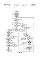
- FIG. 10is a program flow diagram of the protocol followed by a commander station of the present invention.
- FIG. 11is a state diagram of the protocol followed by a responder station of the present invention.
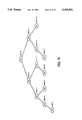
- FIG. 12is a binary tree diagram of BRANCH values and MASK values chosen by a commander station.
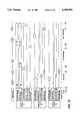
- FIGS. 13 and 14are timing diagrams depicting signals in one commander station according to the method of FIG. 10 and of two responder stations according to the method of
- FIG. 11as the commander station establishes uninterrupted communication with each responder station.
- FIG. 15is a fibonacci tree diagram of LIMIT values chosen by a commander station.
- FIG. 1is a functional block diagram of communication system 30 of the present invention.
- commander stations 10 and 34 and responder stations 40 and 36are coupled to common medium 32 by network interfaces 26 and 60, respectively.
- network interfaces 26 and 60respectively.
- a plurality of commander and responder stationswould be distributed geographically.
- the type of medium selected for communicationdepends on the communication system application; see below for equivalent variations.
- the embodiment depicted in FIG. 1illustrates the invention in an application such as airport baggage handling.
- the mediumis free space through which radio frequency communication are transmissible.
- Commander station 10is designed to achieve a flexible system architecture while incorporating many commercially available components.
- Commander station 10includes personal computer system 12 having data and control bus 14 shared by central processor 16, memory 18, and peripheral controllers 20a and 20c.
- Monitor 22, disk drive 24, and network interface 26connect to individual peripheral controllers 20a-20c via connecting signals 28a-28c, respectively.
- Network interface 26is coupled to common medium 32.
- Network interface 26could be implemented in a chassis separate from the chassis of personal computer system 12 or equivalently could be implemented in combination with the functions of the network interface peripheral controller 20c for connection directly to data and control bus 14.
- commander station 10illustrates several advantages. Communication system configuration and operation are largely dictated by software loaded via disk drive 24, stored in memory 18, and performed by central processor 16. Disk drive 24, memory 18, central processor 16, as well as monitor 22 and peripheral controllers 20a-20c are all conventional, general purpose, and readily available apparatus. Therefore, additional functions and changes to communication system 30 can be made in software with little or no mechanical changes to commander station 10. The operation of commander station software will be discussed below.
- Responder station 40is designed for minimal circuitry to achieve, among other things, small size and low power consumption. Small size permits convenient use, for example, as a baggage tag. Low power consumption permits further size reduction and reduces manufacturing and operating costs. Small size and low manufacturing costs combine to permit implementing responder station 40 as a convenient, dispensable, throw-away item such as a baggage tag, package label, or the like.
- microsequencer 42forms the core of responder station 40.
- Microsequencer 42is a read only memory that produces data signal 48 in response to address signal 44. In operation, a value is presented as address signal 44 once every period of clock signal 46.
- Data signal 48 from microsequencer 42is stored in state register 50 once every period of clock signal 46.
- the output of state register 50is state signal 52, which forms control bus 54.
- Control bus 54causes register transfer operations to be described below.
- a portion of state signal 52defines a portion of address signal 44.
- Microsequencer 42is of a class of devices described by Charles Belove in "Handbook of Modern Electronics and Electrical Engineering,” pp 2135-2142, published by John Wiley & Sons, New York, N.Y. (1986), incorporated herein by reference; and by Y. Chu in “Computer Organization and Microprogramming,” published by Prentice-Hall, Englewood Cliffs, N.J. (1972) incorporated in full herein by reference.
- Network interface 60 of responder station 40is coupled to common medium 32 in a way similar to the coupling of network interface 26 of commander station 10 to common medium 32.
- Network interface 60connects to state register 50 to supply clock signal 46.
- Network interface 60connects to control bus 54 so that send and receive operations are directed in part by state signal 52.
- microsequencer 42When microsequencer 42 is in an appropriate state, data received by network interface 60 is transferred from network interface 60 to command register 56 by data bus 62 in conjunction with load signal 58.
- Command register output 59defines a portion of address signal 44.
- Network interface 60also connects via data bus 62 to memory 64, register array 66, flag register 84, and random number generator 90 for transfer of data between these function blocks, for storage of received data, and for recall of data to be sent.
- data bus 62is byte-wide.
- Network interface 60converts received data from serial to byte-parallel organization. The several devices that connect to data bus 62 make a byte-parallel connection.
- data bus 62is bit-serial.
- Control bus 54in such an embodiment, includes serial clock signal (not shown).
- Register transfer among network interface 60, register array 66, memory 64, flag register 84, and random number generator 90are accomplished in bit-serial fashion with appropriate electrical interfaces known in the art.
- serial and parallel data pathsare implemented.
- Memory 64connects to read/write signal 68 and memory address signal 70 which are part of control bus 54.
- Memory 64is used to store values for responder station identification and data related to the communication system application. For example, when a responder station is used as an airline baggage tag, postal mailing label, or inventory control tag, memory 64 would store data describing a destination for the item to which the tag is attached.
- Register array 66performs functions similar to a multi-port memory. Register array 66 connects to arithmetic-logic unit (ALU) 72 for the presentation of operand signals 74 and 76, and storage of result signal 78. Operand and result signals are multi-bit digital signals for arithmetic operations such as addition, bit-wise parallel logical operations such as logical-AND, and bit-wise serial operations such as shift-left. Register array 66 connects to control bus 54 so that registers to be coupled to operand and result signals are selected and stored according to state signal 52.
- ALUarithmetic-logic unit
- control bus 54connects to ALU 72 to supply opcode signal 80 to ALU 72.
- Opcode signal 80selects one of a plurality of possible operations to be conducted by ALU 72.
- Control bus 54connects to individual bits arranged in flag register 84. Addressed-bit 86, part of flag register 84, is set under control of state signal 52 to indicate whether responder station 40 has been addressed in a received command message. Locked-bit 88, also part of flag register 84, is set under control of state signal 52 to indicate whether responder station 40 should ignore messages from a commander station because responder station 40 has already announced its identification to a commander station. The significance of addressed-bit 86 and locked-bit 88 will become more readily apparent in the description below.
- Random number generator 90connects to control bus 54 and data bus 62 for transferring a random number of a predetermined precision to register array 66. When retained in register array 66, the random number is called an ARBITRATION NUMBER whose function will be discussed below. Circuit techniques for generating a random number in digital format are well known and described, for example, by H. F. Murray in "General Approach for Generating Natural Random Variables", IEEE Transactions on Computers, Vol. C-19, No. 12, pp 1210-1213, December 1970, incorporated herein by reference. In one embodiment, random number generator 90 is similar to an integrated circuit implementation described by Alan Folmsbee, et.
- FIG. 2is a functional block diagram of network interface 26 shown in FIG. 1.
- connecting signal 28ccouple to output buffer 110.
- Byte-parallel loading of output buffer 110is accomplished by network interface peripheral controller 20c shown in FIG. 1.
- Bytesare removed from output buffer 110 by transmitter logic 112 to accomplish several processing objectives.
- a 5-bit cyclic redundancy check (CRC) codeis joined to each 8-bit byte to form a 13-bit word. Redundancy, provided by the 5-bit code, facilitates error detection and limited error correction by responder station 40.
- Table 1describes the format of the 13-bit word and includes a description of the CRC code used in one embodiment.
- Transmitter logic 112also generates transmit serial bit stream 114 which includes a message preamble bit stream, one or more successive 13-bit words from output buffer 110, and a postamble bit stream.
- transmit serial bit stream 114is presented to transmitter 118.
- Transmitter 118in one embodiment produces a radio frequency transmit signal 120 by modulation and couples that signal to antenna 122. Appropriate modulation methods depend on the communication medium.
- modulationincludes, for example, spread spectrum modulation having pseudo noise characteristics.
- Other techniques for transmitter design appropriate to radio transmission and other mediawill be readily apparent to those skilled in the arts applicable to communication on a particular medium.
- a power level of approximately 1 wattis sufficient to excite responder station network interface 60 at distances and noise levels typically required for a communication system for airport baggage handling.
- Receiver 124is coupled to antenna 122 for amplifying and filtering radio frequency received signal 126.
- Receiver 124derives OK-to-transmit signal 116 from power level measurements on received signal 126 and provides signal 116 to transmitter logic 112.
- responder station network interface 60need not generate a transmitted signal using the same modulation technique employed in transmitter logic 112 and transmitter 118, a common method is preferred, for example, in order to minimize circuitry in responder station network interface 60.
- receiver 124removes the carrier signal and other artifacts of modulation generated by responder station network interface 60 in one embodiment by synchronizing with the spread spectrum signal and removing pseudo noise characteristics through known detection and filtering methods.
- Resulting received serial bit stream 128is coupled to receiver logic 130, in one embodiment, for determining whether a proper message has been received and for decomposing the message into successive 8-bit bytes.
- the method and circuitry required to determine whether a proper message has been receiveddepend on the redundancy that responder station network interface 60 incorporates into received serial bit stream 128.
- responder station 40may transmit at a power level of 1 milliwatt or less.
- Multiple and more sophisticated error detection schemes transmitted from responder station 40will extend the limit of physical separation between commander station 10 and responder station 40. Error detection schemes are well known. Such schemes may also permit reliable communication in environments having substantial noise levels.
- limits to the complexity and power consumption of responder station 40may limit the extent of encoding circuitry therein.
- receiver logic 128decomposes, decodes, detects, and to a limited extent corrects errors in received serial bit stream 128.
- Network interface peripheral controller 20cresponsive to OK-to-transmit signal 116 and proper-message-received signal 132, generates signals on data and control bus 14 from which central processor 16 can determine whether a proper message has been received as of a predetermined time after transmission and if not, whether no message was received.
- Other control signalsare generated and sensed to orchestrate the loading of output buffer 110 and the unloading of input buffer 134 under control of central processor 16.
- FIG. 3is a functional block diagram of responder station network interface 60 shown in FIG. 1.
- the configuration illustrated in FIG. 3performs functions similar to those already described above for commander station network interface 26. Differences between the two serve primarily to limit the complexity of responder station circuitry.
- Data bus 62connects to transmitter logic 160.
- transmitter logic 160When directed by microsequencer 42 via signals on control bus 54, transmitter logic 160 generates a message preamble bit stream. Then, for each bit of each word read from memory 64 or register array 66, transmitter logic 160 develops a Viterbi code. Functional descriptions suitable for designing circuits or computer programs for generating Viterbi and similar convolutional codes are explained in "Error Control Coding: Fundamentals and Applications," by Shu Lin and Daniel J.
- Message signal 162presents the codes to transmitter 164. Following the last code, transmitter logic 160 generates a message postamble bit stream. Transmitter 164 modulates message signal 162 in a way compatible with receiver 124 and receiver logic 130. The resulting transmit radio frequency signal 166 is coupled to antenna 168. Redundancy, provided by the Viterbi codes, facilitates error detection and limited error correction when the message is received at commander station 10.
- Receiver 170is coupled to antenna 168 for amplifying and filtering radio frequency received signal 172.
- Receiver 170derives wake-up signal 174 from power-level measurements on received signal 172 and provides wake-up signal 174 to power control and restart circuits not shown.
- non-critical circuitry in responder station 60is powered by battery only after the preamble of a packet has been detected.
- Receiver 170also removes the carrier signal and other artifacts of modulation generated by commander station network interface 26 in one embodiment by synchronizing with the spread spectrum signal and removing pseudo noise characteristics through detection, demodulation, decoding, and filtering methods known in the radio communication arts.
- Resulting received serial bit stream 176is coupled to receiver logic 178.
- receiver logic 178performs several functions: Determining whether a proper byte has been received, consequently generating improper-byte-received signal 180, and decomposing the packet into successive 8-bit bytes forming received message signal 182. The method and circuitry required to determine whether a proper byte has been received depend on the redundancy that commander station network interface 26 incorporates into transmit serial bit stream 114. Receiver logic 178 detects the first byte of a command and in response generates load signal 58. Clock signal 46 is also generated by receiver logic 178 to drive state register 50.
- Microsequencer 42 and network interface 60cooperate via control bus 54 which includes improper-byte-received signal 180.
- Other signals included in control bus 54known in the art and not shown, orchestrate transfer of bytes between memory 64, register array 66, transmitter logic 160, and receiver logic 178. If an improper byte is received, as indicated by improper-byte-received signal 180, microsequencer 42 responds by reverting to an idle state and ignoring incoming bytes until another command is received.
- FIG. 4is a diagram of the packet format sent by commander station 10 to responder station 40.
- Each command packet 140includes, in order of transmission, a preamble followed by a command followed by a postamble.
- the preamble and postambleare designed for synchronizing a transmitter circuit and a receiver circuit for a particular packet.
- the preamble bit streamcomprises 768 ⁇ 1 ⁇ bits followed by a 7-bit Barker code of ⁇ 0001101 ⁇ .
- the postamblecomprises a 7-bit Barker code of ⁇ 1110010 ⁇ .
- each bit of the command formatis modulated using a pseudo noise (PN) sequence for direct sequence spread spectrum communication.
- the sequenceis generated in part by a linear feedback shift register (LFSR) of the form [5,2].
- LFSRlinear feedback shift register
- the input to the first of five registersis the result of combining the output of register 5 by exclusive-OR with the output of register 2.
- the generator in this embodimenthas 32 states so that the 1 and 0 states occur with equal probability. Since the LFSR generates only 31 states, an additional state is inserted by support circuitry.
- FIG. 5is a table that describes several commands and refers to command formats described in FIG. 6.
- each commandbegins with an opcode and has one of four formats varying in length from 3 bytes to 258 bytes. Opcode values were selected to facilitate accurate decoding and obtain high noise immunity.
- Each byteis an 8-bit word as it would appear in output buffer 110 and on received message signal 182.
- the opcode hexadecimal valueis stored on receipt in command register 56. Bytes following the opcode have the following meanings.
- MASK and BRANCH as used in format 142are binary numbers chosen by a commander station to specify a group of responder stations that should act on the command and should reply.
- LOCAL ID in format 142is a unique identification number assigned, for example, by the communication system installer to each commander station 10, 34 coupled to common medium 32. Responder stations 36, 40 coupled to common medium 32 can then direct a response to one of several commander stations 10, 34 by, for example, including a particular LOCAL ID in each response.
- Responder stations 36, 40 coupled to common medium 32can then direct a response to one of several commander stations 10, 34 by, for example, including a particular LOCAL ID in each response.
- an ARBITRATION NUMBERis a short value, for example 1 byte, chosen for self identification by a responder station.
- a TAGas in format 146, is a long value, for example 8 bytes, assigned by a communication system designer at the time a responder station is manufactured or commissioned.
- the ARBITRATION NUMBERdistinguishes responder stations when coupled simultaneously with at least one commander station to a common medium.
- the TAGdistinguishes responder stations throughout the life of the communication system application.
- DATA in format 146includes some or all of the contents for any or all devices including memory 64, register array 66, flag register 84, and random number generator 90.
- FIG. 7is a diagram of the packet format sent by responder station 60 to commander station 10.
- Each response packet 190includes, in order of transmission, a preamble followed by a response followed by a postamble.
- the preamble and postambleare designed for synchronizing a transmitter circuit and a receiver circuit for a particular packet.
- the preamble bit streamcomprises 768 ⁇ 1 ⁇ bits followed by a 7-bit Barker code of ⁇ 0001101 ⁇ .
- the postamblecomprises a 7-bit Barker code of ⁇ 1110010 ⁇ .
- each bit of the response formatis modulated using a pseudo noise (PN) sequence for direct sequence spread spectrum communications.
- the sequenceis generated in part by a linear feedback shift register (LFSR) of the form [6,1] or [8,4,3,2] for either a 64 chip sequence or a 256 chip sequence respectively.
- LFSRlinear feedback shift register
- the input to the first of six registersis the result of combining the output of register 6 by exclusive-OR with the output of register 1.
- the input to the first of eight registersis the result of the exclusive-0R of the outputs of registers 8, 4, 3, and 2.
- the 64 chip sequencerequires less time for signal synchronization than the 256 chip sequence; however, the latter provides better performance in systems having poor signal to noise ratio.
- the generator in this embodimenthas an even binary multiple of states, so that the 1 and 0 states occur with equal probability. Since the LFSR generates one less state, an additional state is inserted by support circuitry.
- a suitable PN modulator circuit of the type employed in transmitter 164see "Spread Spectrum Systems", by R. C. Dixon, published by John Wiley and Sons, Inc. 1984 pp 15-28 and 56-151 incorporated herein by reference.
- Suitable demodulator techniques and circuits of the type used in receiver 124 to recover the response formatare also described at pages 153-290 incorporated herein by reference.
- FIG. 8is a table that describes several responses and refers to response formats described in FIG. 9.
- response formats 192-196include LOCAL ID, ARBITRATION NUMBER, and TAG, which have the meanings already described above.
- LOCAL ID and ARBITRATION NUMBERBy including LOCAL ID and ARBITRATION NUMBER in each response, in cooperation with locked bit 88 one responder station can respond unambiguously to one commander station in the presence of a plurality of commander and responder stations.
- the INVERTED ARBITRATION NUMBER in format 192is the binary ones-complement of the ARBITRATION NUMBER and is included for increased accuracy of communication.
- REVISION in format 192is a one-byte value set by a communication system developer at the time of manufacture or commissioning of a responder station.
- REVISIONrepresents the responder station configuration and connotes its capability.
- STATUS in format 196is a one-byte code chosen by responder station 40 to convey current conditions of important system events such as low battery, uncorrectable data received, write protection, and similar information which may indicate to commander station 10 that communication should be repeated or abandoned.
- DATA in response format 194includes some or all of the contents of any or all devices including memory 64, register array 66, flag register 84, or random number generator 90.
- a communication systemincludes commander and responder stations that adhere to a method of communicating called a protocol.
- the protocol of the present inventionplaces different requirements on a commander station than on a responder station.
- commander station methodFIG. 10
- responder station methodFIG. 11
- Operation according to the present inventionproduces the following characteristic effects at the system level.
- a commander stationwill not begin transmitting during the transmission by another commander station or by a responder station.
- Operation, according to the present inventiondoes not prevent more than one commander station from beginning transmission simultaneously; however, it is feasible to couple commander stations to a second medium or to constrain commander stations to a second or expanded protocol on common medium 32.
- commander stations 10 and 34include personal computer system 12, which can be augmented with a peripheral controller for operation over ethernet. Communication over the second medium can be used to prevent simultaneous broadcast over common medium 32.
- a second protocol on common medium 32may include operator action to assign time slots, back off delays, or similar means for media access whether central or distributed.
- a responder stationwill not transmit unless it has first received a command to which it determines it must respond. The response is made within a predetermined time immediately following receipt of the command.
- a commander stationcan form a command in a manner calling for all, more than one, or one responder station to respond.
- An important object of the communication system protocol in a communication system of the present inventioni.e. uninterrupted communication, is achieved after a commander station determines how to cause only one responder station to respond.
- the program flow diagram of FIG. 10 and the state diagram of FIG. 11describe how uninterrupted communication between one commander station and each responder station is achieved when a plurality of commander stations and a plurality of responder stations are simultaneously coupled to a common medium.
- FIG. 10is a program flow diagram of the protocol followed by a commander station of the present invention.
- a practical example of a communication systemwill be used to describe the flow diagram.
- a commander stationmay be at a fixed operator station within radio range of a moving belt conveying baggage toward a Y-junction of conveyors.
- the commander stationcan control the routing of each bag through the junction onto one of two conveyors.
- each responder stationalso has information in memory 64 describing its sequential position on the conveyor. Such a sequence number could be a date and time of day when the bag passed through a chute upstream of the commander station.
- commander station 10specifies a group of responder station addresses by choosing values for BRANCH and MASK. BRANCH and MASK values are determined in a manner to be explained by reference to FIG. 12 below. In one embodiment, the initial group specification, i.e. BRANCH and MASK values, would specify all possible responder stations.
- Commander station 10 at block 212generates an "identify, clear, and generate" (IDCG) command having a format according to FIGS. 4, 5, and 6.
- IDCG messageWhen the media is clear to broadcast, block 214, as indicated by OK-to-transmit signal 116, the IDCG message is broadcast, block 216.
- An IDCG messagecauses each responder station that is a member of the group to clear locked-bit 88, generate a random number and retain it as its ARBITRATION NUMBER, and broadcast a response.
- the responder station's reactions to ID, IDG, IDC, and IDCG commandsare explained further in reference to FIG. 11 below.
- Commander station 10now loops through blocks 220 and 218 for a response to be received as indicated by OK-to-transmit signal 116 or a time out elapsed condition. If a response was received, as indicated by a false state of OK-to-transmit signal 116, commander station 10 at block 222 determines whether a collision occurred, as indicated by a false state of proper-message-received signal 132. If commander station 10 determines that a collision occurred, it will determine at block 224 whether all possible members of the initial group of responder station addresses specified at block 210 have been addressed in an ID, IDG, IDC, or IDCG command. How this determination is made will be further explained with reference to FIG. 12 below.
- commander station 10If all subgroups have not been tried, the commander station again specifies a group of responder station addresses, for example, a subgroup or disjoint group of a prior group.
- commander station 10At block 228 commander station 10 generates an ID command according to FIGS. 4, 5, and 6 and continues the method from block 214.
- commander station 10concludes that no response was transmitted and continues the method at block 224.
- commander station 10determines and validates the responding responder station's ARBITRATION NUMBER according to response format 192 using ARBITRATION NUMBER and INVERTED ARBITRATION NUMBER. According to a particular system communication objective, commander station 10 now selects a command from FIG. 5 which will cause the responder station to set its locked-bit 88. For determining baggage destination and positional sequence on the conveyor, commander station 10 could select RD. Using the appropriate command format shown in FIG.
- commander station 10generates a message at block 232, loops until the OK-to-transmit signal indicates that the medium is clear to broadcast at block 234, then broadcasts the command at block 236.
- Commander station 10again awaits a proper response message by looping at block 238 through block 240. If a predetermined time elapses at block 240, commander station 10 continues the method at block 234. If a response is received without error at block 244, as indicated by proper-message-received signal 132, then two party uninterrupted communication between commander station 10 and one responder station 60 has been established. Further communication maybe required, as indicated by the STATUS code in the received response format 192 or to accomplish other system communication objectives.
- commander station 10determines that no further subgroup, super group, or disjoint group remains to be commanded using the ID command.
- IDGidentify and generate command
- a responder station that has been identified at block 244will not respond, since its locked-bit 88 has been set. Collisions are less likely to occur with each pass through the loop from block 214 to block 248 because a smaller number of responder stations can respond. Hence, the method of FIG. 10 converges toward identifying all responder stations.
- the communication system designermust select the precision of BRANCH and MASK values to assure conversion within system time allowances, for example, 8-bit BRANCH and MASK values are compatible with conveyor speeds and radio ranges needed for airport baggage handling.
- FIG. 11is a state diagram of the protocol followed by a responder station of the present invention.
- Responder station 40begins in idle state 310 when power is applied or restored according to wake-up signal 174.
- the idle stateis indicated by contents of command register 56 not corresponding to a valid command.
- the idle stateis reentered to interrupt command processing when improper-byte-received signal 180 is raised by receiver logic 178.
- a valid command loaded into command register 56causes state transition to address check state 312.
- commander and responder stationsemployed radio transceivers for network interfaces 60 and 26. Then, suppose responder station 40 is within range of two commander stations 10 and 34, but commander stations 10 and 34 are out of range of each other. When commander stations 10 and 34 validly produce back to back commands, the delay interposed by state 314 prevents responder station 40 (not addressed by commander station 10 in the first occurring command) from responding to commander station 34 in the second occurring command. Without the delay, a collision could occur that may confuse commander station 10.
- Each recognized command opcodecauses microcode execution to begin at a section of microcode for the purpose of directing microseqencer operations to process the particular received command.
- Four commandsare illustrated as separate states 318 through 324 and other commands are illustrated in summary by pseudo state 326.
- state 318is entered for identify, clear, and generate operations.
- An IDR response(according to FIGS. 8 and 9) is selected, locked-bit 88 is cleared, the content of random number generator 90 is stored in register array 66 as ARBITRATION NUMBER, and transition is made to state 328.
- state 320is entered for identify, and generate operations.
- An IDR responseis selected and a new ARBITRATION NUMBER is generated as already described for state 318. Transition is then made to state 328.
- state 322is entered for identify and clear operations.
- An IDR responseis selected and locked-bit 88 is cleared. Transition is then made to state 328.
- state 324is entered for an identify operation. An IDR response is selected. Transition is then made to state 328.
- locked-bit 88may be set and other functions may be performed. Other functions may include writing data to memory 64, writing data to register array 66, altering the state of registers including flag register 84, and other operations controlling responder station configuration and operation. Transition is then made to state 328.
- the response selected by a prior stateis generated according to FIGS. 7, 8, and 9 and broadcast.
- the responseis broadcast as it is being generated.
- Transition to idle state 310is made, after broadcasting the response.
- responder station 40does not wait for clear medium prior to broadcasting the response. According to the present invention, collision detection by responder stations is not necessary to accomplish uninterrupted communication.
- FIG. 12is a binary tree diagram of BRANCH values and MASK values chosen by a commander station.
- a treeis a type of graphic representation. There are several types of trees known in mathematics and computer science. The tree depicted is a binary tree where a node can have two branches, shown descending left and right from a node. Each node corresponds to a unique combination of values for BRANCH and MASK, which are n-bit binary numbers having the same precision. As illustrated, BRANCH and MASK are 3-bit binary numbers. In a communication system for airport baggage handling, 8-bit numbers would be used. The precision employed for BRANCH and MASK must be identical to the precision selected for ARBITRATION NUMBER generated by responder station 40.
- ARBITRATION NUMBERis the value retained in register array 66 from random number generator 90.
- MASKis 0 and BRANCH is 0 all values of ARBITRATION NUMBER satisfy the expression, i.e. all responder stations coupled to common medium 32 conclude they are addressed.
- MASKhas a ⁇ 1 ⁇ bit in every position, then the expression is satisfied for only one value of ARBITRATION NUMBER.
- BRANCH at bit position ⁇ q ⁇must be ⁇ 0 ⁇ when MASK at bit position ⁇ q ⁇ is ⁇ 0 ⁇ , for all values of ⁇ q ⁇ .
- BRANCHcan take two values for that bit position which correspond to the left and right branches of a binary tree.
- nodes 702 and 703MASK is ⁇ 1 ⁇ in bit position ⁇ r ⁇ .
- the corresponding bit position of BRANCHis ⁇ 0 ⁇ at node 702 and ⁇ 1 ⁇ at node 703.
- MASKis ⁇ 1 ⁇ at bit positions ⁇ r ⁇ and ⁇ s ⁇ .
- the value for BRANCH at node 707is the parent node BRANCH value (001 at node 703) modified by forcing a ⁇ 1 ⁇ (for the right-hand branch) at bit position ⁇ s ⁇ , hence 011.
- the BRANCH and MASK values for any node in the treecan be determined.
- MASK bit positionshave been given in an order right to left. Any other order of bit positions would be equivalent.
- commander station 10When commander station 10 broadcasts a request for identification (an ID, IDC, IDG, or IDCG command) one of three events can occur. BRANCH and MASK values given at a particular node that represents a first group of responder stations. First, commander station 10 could receive no response from which it could conclude that no responder station in the first group is currently coupled to the common medium 32. Second, a proper response could be received. From that event, commander station 10 could conclude that only one responder station in the first group is currently coupled to common medium 32. Third, from an improper response received, commander station 10 could conclude that a collision of more than one response occurred. An improper response could be caused by, for example, weak coupling, high noise levels, or weak received signals. However, these causes can be treated in the same way as a collision to simplify the commander station protocol without substantially degrading system performance for applications including airport baggage handling. Therefore, an improper response simply merits further search.
- an improper responsesimply merits further search.
- An efficient search for the identity of each of several responding responder stationsis equivalent to an efficient search for the leaves of a binary tree.
- a leafis a node having no further branches.
- the nodeis a leaf. Tree search methods are easily implemented using known computer programming methods.
- Tree search methodsare essentially of two types, breadth first and depth first.
- a particular communication system applicationmay use one method or the other to optimize commander station computing time and memory space objectives.
- An explanation of these methods using the programming language PASCALis given by E. Horowitz and S. Sahni in "Fundamentals of Data Structures in PASCAL” pp 203-265 and 326-332 published by Computer Science Press Inc., Rockville, Md. (1984), incorporated herein by reference.
- FIG. 12illustrates a sequence of BRANCH and MASK values used by commander station 10 to identify responder stations.
- Timing diagrams in FIGS. 13 and 14illustrate the same sequence showing decisions at commander station 10 decision blocks (according to the commander station method of FIG. 10) and responder station control signals (according to the responder station method of FIG. 11) as commander station 10 establishes uninterrupted communication with each responder station.
- responder station 40has determined that it is addressed, has cleared its locked-bit 88, has generated ARBITRATION NUMBER 101, and has begun transmitting response IDR.
- responder station 36has determined that it has been addressed, has generated ARBITRATION NUMBER 111, and has begun transmitting response IDR.
- simultaneous transmissionscollide on common medium 32.
- Responder station 40is not addressed because ARBITRATION NUMBER (101) ANDed with MASK (001) yields 001 which is not equal to BRANCH (000).
- responder station 36is not addressed. Neither station responds.
- time out at block 218occurs.
- a third group of responder station addressesis chosen. From FIG. 12 the appropriate group is specified by traversing the tree according to a search method. If a breadth first search were used, all nodes at the same level would be visited before testing at a deeper level. Hence, node 703 would be next. If a depth first search were used, search would proceed upward from node 702 (because it is a leaf) and then downward from the first node having an untested branch. Hence, up to node 701 and down to node 703. As a refinement to either method, node 703 can be skipped because a collision at node 701 and no response at node 702 implies a collision at node 703 without testing. A depth first search would now traverse from node 703 directly to node 706. A breadth first search would first consider nodes 704 and 705 and conclude not to visit them because each is a descendent from a leaf node.
- station 40has determined that it is addressed and has begun transmitting response IDR.
- responder station 36determines it is not addressed and remains in state 314.
- time 840shown on FIGS.
- commander station 10has received the response from responder station 40 as a proper message, concluded that only one responder station responded, derived received ARBITRATION NUMBER (101), set BRANCH to received ARBITRATION NUMBER, set MASK to all 1's so that a responder station must match ARBITRATION NUMBER (101) in all bit positions to respond, and begins to perform blocks 232 through 244 in FIG. 10.
- responder station 40has determined that it is addressed, has decoded a read command, has set its locked-bit 88 in state 326, and has begun generating the read response in state 328.
- commander station 10has received the response as a proper message.
- commander station 10has conducted a first two-party uninterrupted command-response scenario from time 840 to time 850 with one responder station.
- commander station 10 for another responder stationproceeds from block 244 to block 224 in FIG. 10.
- responder station 36has determined that it has been addressed and has begun generating an IDR response.
- the responseis received by commander station 10 as a proper message. After time 860, events proceed in a manner similar to events from time 840 to time 850, as commander station 10 conducts a second two-party uninterrupted command-response scenario with a second responder station.
- commander station 10can conclude that all groups have been tested.
- On a breadth first searchall groups have been tested when an investigation of all levels up to the level having all MASK bits set to ⁇ 1 ⁇ yields no node that is not descendent from a leaf node.
- a responder stationconcludes that it has been addressed when ARBITRATION NUMBER logically ANDed with MASK is equal to BRANCH.
- ARBITRATION NUMBERlogically ANDed with MASK is equal to BRANCH.
- MASKlogically ANDed with MASK is equal to BRANCH.
- BRANCH and MASKare replaced with HIGH LIMIT and LOW LIMIT.
- Each of these limit valueshas the same precision as the MASK value.
- responder station 40concludes that it is addressed when HIGH LIMIT is greater than or equal to ARBITRATION NUMBER, and LOW LIMIT is less than or equal to ARBITRATION NUMBER.
- BRANCH and MASKare replaced with a single LIMIT value having the same precision as MASK.
- BOUNDwhich by design choice may be 0 or the maximum permitted by the precision of LIMIT, responder station 40 concludes that it is addressed when ARBITRATION NUMBER is between BOUND and LIMIT, inclusive of both BOUND and LIMIT values.
- limit/bound embodimentAn example of a limit/bound embodiment is implemented with a structure similar to that already described for the branch/mask embodiment. Subtraction capability or equivalent must be added to ALU 72. Operation of microsequencer 42 must be revised to perform the arithmetic operations outlined above in state 312 shown on FIG. 11. The high/low embodiment is implemented with the structure already described for the limit/bound embodiment.
- commander station 10specifies a group of responder station addresses.
- a method using the binary tree of FIG. 12has already been discussed.
- a similar binary tree(not shown) with HIGH and LOW values at each node is used.
- LOWis 0
- HIGHis the maximum value permitted by the precision of the value HIGH.
- the value of LOWis the value of LOW at the parent node and the value of HIGH is a value 1/2 the value of HIGH at the parent node discarding a remainder, if any.
- the value of HIGHis the value of HIGH at the parent node and the value of LOW is 1/2 the value of HIGH at the parent node plus one.
- a binary treehas been described, a tree having more than two branches at each node can be employed to practice the present invention as is readily apparent to those skilled in the art. Trees with varying number of branches at each node can also be employed. Operation of the high/low embodiment is otherwise identical to operation of the branch/mask embodiment already discussed.
- the method used to specify a group of responder station addressesis similar to the method described for a high/low embodiment with a minor variation in the tree.
- BOUNDzero
- the value for LOWis not used and the value for HIGH is used as the LIMIT value at each node.
- BOUNDis a maximum value
- the value for HIGHis not used and the value of LIMIT at each node is the value of LOW.
- Operation of a limit/bound embodimentis otherwise identical to operation of a branch/mask embodiment already discussed. Note that the command at block 232 on FIG. 10 sets locked-bit 88 to prevent unnecessary collisions when an ID command using LIMIT is broadcast subsequently at block 228.
- FIG. 15is a fibonacci tree diagram for use in an example of an embodiment of the type already described as limit/bound.
- An advantage of using a fibonacci treeis that the LIMIT value for a node descendent from a parent node can be derived without a multiplication or division operation. In systems where it is desirable to improve calculation speed or reduce the complexity of circuitry and software at commander station 10, the fibonacci tree is used.
- An implementation of a high/low embodiment using a fibonacci tree similar to FIG. 15is within the ordinary skill of the systems design and programming arts.
- a commander stationcan quickly determine the identity of all responder stations coupled to a common medium at a given time. After the identity of a responder station has been determined, a commander station can conduct uninterrupted communication at any subsequent time using the responder station's ARBITRATION NUMBER. Since the ARBITRATION NUMBER is not unique, there is some risk that at a subsequent time, more than one responder station having a given value for ARBITRATION NUMBER may become coupled to the common medium. For increased accuracy, use of a unique responder station identity, such as the TAG field in format 146 of FIG. 6, may be used for subsequent communication.
- commander station 10When more than one commander station is coupled to a common medium, it is possible for one commander station to thwart the objective of a second commander station. For example, when commander station 10 is attempting to identify all responder stations and commander station 34 issues an IDCG command, commander station 10 may subsequently incorrectly conclude that all responder stations have been identified. Several methods of preventing this incorrect conclusion are available to those skilled in communication and computer programming arts.
- Exemplary methodsinclude enabling a commander station to monitor commands issued by another commander station to avoid inappropriate conclusions; enabling a commander station 10 to record the TAG fields sent in messages to another commander station and communicate directly with each such responder station, perhaps prior to and so simplifying, the task of identifying all responder stations; modifying the communication protocol used among commander stations; and causing a second commander station to delay its own attempt to identify all responder stations until after a time sufficient for a first commander station to identify all responder stations.
- the latter suggestionis practical using the media access control scheme of the present invention. It is practical because the time required to identify a worst-case population of responder stations can be predetermined.
- the present inventioncan be implemented in several alternate embodiments. As already discussed, various alternatives are available for common medium 32 including all media that support forms of electromagnetic energy, all sound, vibration, and pressure wave conducting media, and all media capable of transporting variation in chemical concentration, to name a few. If a medium other than radio communication is selected as an embodiment of the present invention, variations in network interface 26 and 60 can be made by those skilled in the arts that apply to the selected medium. Appropriate signal sensors and generators are well known in applications including measurement and control apparatus. Packet synchronization techniques, packet formats, error detection techniques, and error correction techniques may vary or be omitted as a matter of design choice depending on the need for receiver synchronization, the signal to noise properties of the selected media, and the desired simplicity of network interfaces.
- Another group of alternative embodimentsuses various means to specify a set of responder station identities or designations.
- the embodiments described aboveemploy an ARBITRATION NUMBER selected from a predetermined range of numbers and expressed as part of a message.
- alternate sets of designationsinclude a set of operating modes, a set of modulation techniques, and a range of values used to shift in time all or a portion of a command.
- Various alternativesare also available for specifying (i.e. addressing) a subset of designations.
- the branch/mask, high/low, and limit/bound subset addressing techniquescan each be applied to one or more parametric quantities related to the above mentioned set designations. For example, if one member of the set is characterized by a bandwidth, a channel frequencies, a phase variation, or a duration in time, then a range of each of these parameters could be described by a branch/mask pair of values.
- the BRANCH and MASK values in the message formatcharacterize the transmitted command signal according to a subset of responder stations to which the command is directed.
- the transmitted signalcan be characterized by variation in the spread spectrum chip sequence or initial code within a chip sequence when spread spectrum transmission is employed.
- command signalcan be used to limit or expand the subset of responder stations to which the command is directed.
- commands including RD and WR to set locked-bit 88 and the operation of commands including IDG and IDCG to conditionally clear locked-bit 88show how the command opcode can be used to characterize a command signal according to a selected subset or address range.
- modulation variations, timing variations, or other message content variationscould also be used to set or clear an equivalent of the locked-bit function.
- a responder stationdetermines whether it is addressed by, i.e. whether it is a member of the subset indicated by, a command signal.
- Several arithmetic comparison techniques based on message contenthave been described above.
- Other means, based on whether the signal received by the responder is received without error,are appropriate when variations in modulation are used to address a subset of responder stations. For example, received signal strength below a threshold over one or more frequencies or at a particular time could cause commands to be received or rejected.
- operation of functions similar to locked-bit 88 as already described and variation in spread spectrum chip sequencecould be used to cause commands to be received or rejected.
- each responder stationincludes means for establishing a self designation.
- the self designationis determined by a random number generator, held in a register, and included in a response packet.
- Alternative techniquesinclude various means for sampling a random process to acquire an analog parametric value and using either a digital or an analog value to control the functions of network interface 60.
- Network interface 60can be constructed and operated in several alternative embodiments to transmit a response packet in a way characterized by the responder station self designation. All of the following variations could be used in embodiments that fall within the scope of the present invention: variations in the modulation technique, including variation within a range of values used to shift in time all or a portion of a response; variation in the spread spectrum chip sequence or initial code within a chip sequence when spread spectrum transmission is employed; variation in message content including preamble, postamble, response type indicator e.g. IDR, RDR, and WDR, register contents, status and locked-bit information; and variation based on signal rejection including variation in bandwidth, channel frequencies, signal phase variations, signal duration, or variation in the redundancies used to detect or correct transmission error.
- variations in the modulation techniqueincluding variation within a range of values used to shift in time all or a portion of a response
- variation in the spread spectrum chip sequence or initial code within a chip sequence when spread spectrum transmission is employedvariation in message content including preamble, postamble, response type indicator
- Another group of alternative embodimentsuses alternative means for selecting a subgroup in response to collision detection.
- the tree search methodthat was described as part of the commander station protocol can be implemented in various ways depending on the selected representation of the tree in commander station memory 18.
- Binary treeshave been described above.
- Other tree structuresincluding n-ary trees could be employed to perform the commander station identification function in an equivalent manner.
- strings, arrays, stacks, pointers, linked lists, or derivative memory organizationsare feasible and equivalent.
- tree search methodsinclude depth first, breadth first, and combinations of both depth and breadth searching.
- Each computer used as part of commander station 10 and as part of responder station 40includes hardware and software designed to conduct the protocol shown and described in FIGS. 10 and 11 respectively.
- Variations in the extent and complexity of hardware and softwareare well known by designers of ordinary skill in communication and computer arts.
- Equivalent hardwarecan include the general purpose computer such as an IBM PC; a calculator, such as an HP21C; the special purpose computer, such as application specific automated controllers used in weighing systems; the microprocessor based system, such as a circuit using an Intel 8048; the microsequencer based system using programmable devices and logic devices; and the integrated circuit or chip set, such as developed from a cell library using semiconductor device design techniques.
- Variations in the extent and complexity of software compatible with one or more of the above mentioned hardware variationsare also well known by the programmer of ordinary skill.
- a computeris said to conclude a certain result when it has determined the state of a control function.
- variations in the form of the result of the control functionare well known.
- a parameter that results from a first control function and is relied upon by a second control functioncan take the form of a signal when the second control function is in part hardware or the form of a pointer, value, or symbol stored in a register or memory when the second control function is in part software.
Landscapes
- Engineering & Computer Science (AREA)
- Computer Networks & Wireless Communication (AREA)
- Radar, Positioning & Navigation (AREA)
- Remote Sensing (AREA)
- Physics & Mathematics (AREA)
- Signal Processing (AREA)
- General Physics & Mathematics (AREA)
- Toxicology (AREA)
- Health & Medical Sciences (AREA)
- Theoretical Computer Science (AREA)
- Artificial Intelligence (AREA)
- Computer Vision & Pattern Recognition (AREA)
- Electromagnetism (AREA)
- General Health & Medical Sciences (AREA)
- Computer Hardware Design (AREA)
- Microelectronics & Electronic Packaging (AREA)
- Mobile Radio Communication Systems (AREA)
- Communication Control (AREA)
Abstract
Description
TABLE 1 ______________________________________ Bit Order of D7, D6, . . . D0, P4, P3, . . . P0 Transmission (P0 transmitted first) CRC Generation P0 = D1 + D2 + D5 + D7 Equations P1 = D1 + D3 + D4 + D6 P2 = D0 + D2 + D3 + D6 + D7 P3 = D0 + D4 + D5 + D6 + D7 P4 = D0 + D1 + D2 + D3 + D4 + D5 ______________________________________
Claims (51)
Priority Applications (5)
| Application Number | Priority Date | Filing Date | Title |
|---|---|---|---|
| US07/990,918US5365551A (en) | 1992-12-15 | 1992-12-15 | Data communication transceiver using identification protocol |
| US08/263,210US5583850A (en) | 1992-12-15 | 1994-06-21 | Data communication system using identification protocol |
| US08/556,818US5787174A (en) | 1992-06-17 | 1995-11-02 | Remote identification of integrated circuit |
| US08/581,937US6144916A (en) | 1992-05-15 | 1996-01-02 | Itinerary monitoring system for storing a plurality of itinerary data points |
| US08/726,560US5841770A (en) | 1992-12-15 | 1996-10-07 | Data communication system using indentification protocol |
Applications Claiming Priority (1)
| Application Number | Priority Date | Filing Date | Title |
|---|---|---|---|
| US07/990,918US5365551A (en) | 1992-12-15 | 1992-12-15 | Data communication transceiver using identification protocol |
Related Child Applications (1)
| Application Number | Title | Priority Date | Filing Date |
|---|---|---|---|
| US08/263,210ContinuationUS5583850A (en) | 1992-05-15 | 1994-06-21 | Data communication system using identification protocol |
Publications (1)
| Publication Number | Publication Date |
|---|---|
| US5365551Atrue US5365551A (en) | 1994-11-15 |
Family
ID=25536654
Family Applications (3)
| Application Number | Title | Priority Date | Filing Date |
|---|---|---|---|
| US07/990,918Expired - LifetimeUS5365551A (en) | 1992-05-15 | 1992-12-15 | Data communication transceiver using identification protocol |
| US08/263,210Expired - LifetimeUS5583850A (en) | 1992-05-15 | 1994-06-21 | Data communication system using identification protocol |
| US08/726,560Expired - LifetimeUS5841770A (en) | 1992-12-15 | 1996-10-07 | Data communication system using indentification protocol |
Family Applications After (2)
| Application Number | Title | Priority Date | Filing Date |
|---|---|---|---|
| US08/263,210Expired - LifetimeUS5583850A (en) | 1992-05-15 | 1994-06-21 | Data communication system using identification protocol |
| US08/726,560Expired - LifetimeUS5841770A (en) | 1992-12-15 | 1996-10-07 | Data communication system using indentification protocol |
Country Status (1)
| Country | Link |
|---|---|
| US (3) | US5365551A (en) |
Cited By (157)
| Publication number | Priority date | Publication date | Assignee | Title |
|---|---|---|---|---|
| US5500650A (en)* | 1992-12-15 | 1996-03-19 | Micron Technology, Inc. | Data communication method using identification protocol |
| US5550547A (en)* | 1994-09-12 | 1996-08-27 | International Business Machines Corporation | Multiple item radio frequency tag identification protocol |
| US5568512A (en)* | 1994-07-27 | 1996-10-22 | Micron Communications, Inc. | Communication system having transmitter frequency control |
| US5583850A (en)* | 1992-12-15 | 1996-12-10 | Micron Technology, Inc. | Data communication system using identification protocol |
| US5600795A (en)* | 1993-08-28 | 1997-02-04 | U.S. Philips Corporation | Local network operating in asynchronous transfer mode (ATM) generating control cell containing information about the user, address of the station, and user-related identification |
| EP0831618A2 (en) | 1996-09-19 | 1998-03-25 | Texas Instruments Deutschland Gmbh | Improvements in or relating to information/data transfer systems |
| WO1998027441A1 (en)* | 1996-12-19 | 1998-06-25 | Micron Communications, Inc. | Methods of processing wireless communication, methods of processing radio frequency communication, and related systems |
| US5774022A (en)* | 1996-08-29 | 1998-06-30 | Micron Communications, Inc. | Digital clock recovery loop |
| US5822341A (en)* | 1995-04-06 | 1998-10-13 | Advanced Hardware Architectures, Inc. | Multiport RAM for use within a viterbi decoder |
| WO1999016703A1 (en) | 1997-09-26 | 1999-04-08 | Gilbarco Inc. | Fueling system with wireless data transfer |
| WO1999016702A1 (en) | 1997-09-26 | 1999-04-08 | Gilbarco Inc. | Fuel dispensing system with prepayment means linked to a transponder |
| US5896097A (en)* | 1996-03-06 | 1999-04-20 | Schlumberger Resource Management Services, Inc. | System for utility meter communications using a single RF frequency |
| US5914980A (en)* | 1995-09-21 | 1999-06-22 | Kabushiki Kaisha Toshiba | Wireless communication system and data storage medium |
| EP0932051A1 (en)* | 1998-01-22 | 1999-07-28 | EM Microelectronic-Marin SA | Electronic communication system between a base station and transponders |
| WO1999043128A1 (en)* | 1998-02-19 | 1999-08-26 | Micron Communications, Inc. | Method of identifying wireless units |
| WO1999043127A1 (en)* | 1998-02-19 | 1999-08-26 | Micron Communications, Inc. | Method of identifying wireless units |
| US5970398A (en)* | 1996-07-30 | 1999-10-19 | Micron Communications, Inc. | Radio frequency antenna with current controlled sensitivity |
| US6002344A (en)* | 1997-11-21 | 1999-12-14 | Bandy; William R. | System and method for electronic inventory |
| US6052068A (en)* | 1997-03-25 | 2000-04-18 | Frederick J. Price | Vehicle identification system |
| US6061344A (en)* | 1998-02-19 | 2000-05-09 | Micron Technology, Inc. | Method of addressing messages and communications system |
| US6072801A (en)* | 1998-02-19 | 2000-06-06 | Micron Technology, Inc. | Method of addressing messages, method of establishing wireless communications, and communications system |
| US6100765A (en)* | 1998-01-09 | 2000-08-08 | Micron Technology, Inc. | Digital clock recovery loop |
| US6104279A (en)* | 1998-03-23 | 2000-08-15 | Atmel Corporation | Method of communication between a plurality of remote units and a control unit |
| US6111911A (en)* | 1995-06-07 | 2000-08-29 | Sanconix, Inc | Direct sequence frequency ambiguity resolving receiver |
| US6118789A (en)* | 1998-02-19 | 2000-09-12 | Micron Technology, Inc. | Method of addressing messages and communications system |
| US6125454A (en)* | 1993-05-14 | 2000-09-26 | Siemens Aktiengesellschaft | Method for reliably transmitting information on a bus |
| US6130602A (en)* | 1996-05-13 | 2000-10-10 | Micron Technology, Inc. | Radio frequency data communications device |
| US6134692A (en)* | 1997-03-21 | 2000-10-17 | Kabushiki Kaisha Toshiba | Information identification system for identifying response units by a control unit, and the control unit and the response units for the information identification system |
| US6169938B1 (en) | 1995-12-08 | 2001-01-02 | Marconi Commerce Systems Inc. | Transponder communication of ORVR presence |
| US20010020198A1 (en)* | 1997-09-26 | 2001-09-06 | Wilson Amy Hetz | Fuel dispensing system for cash customers |
| US20020011932A1 (en)* | 1998-06-02 | 2002-01-31 | Rf Code, Inc. | Object identification system with adaptive transceivers and methods of operation |
| US6466131B1 (en) | 1996-07-30 | 2002-10-15 | Micron Technology, Inc. | Radio frequency data communications device with adjustable receiver sensitivity and method |
| US20020149480A1 (en)* | 2001-02-12 | 2002-10-17 | Matrics, Inc. | Method, system, and apparatus for remote data calibration of a RFID tag population |
| US6487681B1 (en)* | 1992-11-20 | 2002-11-26 | Micron Technology, Inc. | In-sheet transceiver testing |
| US20030014646A1 (en)* | 2001-07-05 | 2003-01-16 | Buddhikot Milind M. | Scheme for authentication and dynamic key exchange |
| US20030019929A1 (en)* | 2001-05-31 | 2003-01-30 | Stewart Roger G. | Methods and apparatuses to identify devices |
| US20030052161A1 (en)* | 2001-09-18 | 2003-03-20 | Rakers Patrick L. | Method of communication in a radio frequency identification system |
| US6545604B1 (en) | 1999-07-01 | 2003-04-08 | Micron Technology, Inc. | Methods for electronic tracking of units originating from a common source, and assemblies comprising transponders attached to meat spikes |
| US6571151B1 (en) | 1998-03-06 | 2003-05-27 | Russel Dean Leatherman | Wireless nozzle interface for a fuel dispenser |
| US20030112128A1 (en)* | 2000-02-28 | 2003-06-19 | Littlechild Stuart Colin | Radio frequency identification transponder |
| US20030137403A1 (en)* | 2001-10-09 | 2003-07-24 | Carrender Curtis L. | Methods and apparatuses for identification |
| US20030214389A1 (en)* | 2002-04-01 | 2003-11-20 | Matrics, Inc. | Method and system for optimizing an interrogation of a tag population |
| US6674359B1 (en)* | 1999-10-14 | 2004-01-06 | Texas Instruments Incorporated | Method of identifying several transponders |
| US20040034561A1 (en)* | 2000-04-07 | 2004-02-19 | Smith Glen David | Interactive marketing system |
| US6696879B1 (en) | 1996-05-13 | 2004-02-24 | Micron Technology, Inc. | Radio frequency data communications device |
| US20040052268A1 (en)* | 1999-05-19 | 2004-03-18 | 3Com Corporation | System for transporting ethernet frames over very high speed digital subscriber lines |
| WO2003036401A3 (en)* | 2001-10-15 | 2004-04-15 | Siemens Ag | Method for detecting a number of field devices in a device configuration |
| US20040111338A1 (en)* | 1997-11-21 | 2004-06-10 | Matrics, Inc. | System and method for electronic inventory |
| US20040135674A1 (en)* | 2002-10-18 | 2004-07-15 | Wayne Shanks | Method for the efficient reading of a population of radio frequency identification tags with unique identification numbers over a noisy air channel |
| US20040134984A1 (en)* | 2002-10-25 | 2004-07-15 | Powell Kevin J. | Optimization of a binary tree traversal with secure communications |
| US6774685B2 (en) | 1996-05-13 | 2004-08-10 | Micron Technology, Inc. | Radio frequency data communications device |
| US20040160310A1 (en)* | 2003-02-14 | 2004-08-19 | Mao-Song Chen | Radio frequency identification device |
| US6812852B1 (en) | 1994-09-09 | 2004-11-02 | Intermac Ip Corp. | System and method for selecting a subset of autonomous and independent slave entities |
| US20040222898A1 (en)* | 2000-10-23 | 2004-11-11 | Gabig Jerome S. | Apparatus and method for managing luggage handling |
| US20040236699A1 (en)* | 2001-07-10 | 2004-11-25 | American Express Travel Related Services Company, Inc. | Method and system for hand geometry recognition biometrics on a fob |
| US6836468B1 (en) | 1996-05-13 | 2004-12-28 | Micron Technology, Inc. | Radio frequency data communications device |
| US6842121B1 (en) | 1996-04-04 | 2005-01-11 | Micron Technology, Inc. | RF identification system for determining whether object has reached destination |
| US20050029320A1 (en)* | 1999-03-01 | 2005-02-10 | Thule Sweden Ab | Vertically engageable carrier foot |
| US20050040961A1 (en)* | 1995-04-11 | 2005-02-24 | Tuttle John R. | RF identification system with restricted range |
| US20050071231A1 (en)* | 2001-07-10 | 2005-03-31 | American Express Travel Related Services Company, Inc. | System and method for securing rf transactions using a radio frequency identification device including a random number generator |
| US6876294B1 (en)* | 1998-08-18 | 2005-04-05 | Identec Limited | Transponder identification system |
| US20050088286A1 (en)* | 1994-09-09 | 2005-04-28 | Heinrich Harley K. | Radio frequency identification system with write broadcast capability |
| US6919793B2 (en) | 1994-09-09 | 2005-07-19 | Intermec Ip Corp. | Radio frequency identification system write broadcast capability |
| US20050160003A1 (en)* | 2001-07-10 | 2005-07-21 | American Express Travel Related Services Company, Inc. | System and method for incenting rfid transaction device usage at a merchant location |
| WO2005069525A1 (en)* | 2004-01-16 | 2005-07-28 | Zih Corp | A method and system for calculating and verifying the integrity of data in a data transmission system |
| US6941124B1 (en) | 1996-05-13 | 2005-09-06 | Micron Technology, Inc. | Method of speeding power-up of an amplifier, and amplifier |
| US20050237965A1 (en)* | 2004-01-08 | 2005-10-27 | Yefim Kuperschmidt | Method and devices for multicasting information over a network that applied a distributed media access control scheme |
| US20050242927A1 (en)* | 2004-04-28 | 2005-11-03 | Atmel Co. | Communication method in RFID or remote sensor systems |
| US20050242196A1 (en)* | 2001-05-31 | 2005-11-03 | Alien Technology Corp. | Integrated circuits with persistent data storage |
| US20060012387A1 (en)* | 2004-06-29 | 2006-01-19 | Symbol Technologies, Inc. | Systems and methods for testing radio frequency identification tags |
| US20060061453A1 (en)* | 1997-02-27 | 2006-03-23 | Tuttle John R | System and method for locating individuals and equipment, airline reservation system, communication system |
| US20060071757A1 (en)* | 2004-09-24 | 2006-04-06 | Burghard Brion J | Communication methods, systems, apparatus, and devices involving RF tag registration |
| US20060176154A1 (en)* | 2000-02-28 | 2006-08-10 | Littlechild Stuart Colin | Radio frequency identification transponder |
| US7092043B2 (en) | 1998-11-12 | 2006-08-15 | Broadcom Corporation | Fully integrated tuner architecture |
| US20060279408A1 (en)* | 1997-05-14 | 2006-12-14 | Zih Corp. | Enhanced identification system |
| US20070135179A1 (en)* | 2000-07-26 | 2007-06-14 | Hardman Gordon E | System for conserving battery life in a battery operated device |
| US7258276B2 (en) | 2000-10-20 | 2007-08-21 | Promega Corporation | Radio frequency identification method and system of distributing products |
| US20070222611A1 (en)* | 2000-04-26 | 2007-09-27 | Micron Technology, Inc. | Automated antenna trim for transmitting and receiving semiconductor devices |
| US20080033722A1 (en)* | 2001-07-10 | 2008-02-07 | American Express Travel Related Services Company, Inc. | Method and system for hand geometry recognition biometrics on a fob |
| US20080055073A1 (en)* | 2006-09-06 | 2008-03-06 | Lutron Electronics Co., Inc. | Method of discovering a remotely-located wireless control device |
| US20080068204A1 (en)* | 2006-09-06 | 2008-03-20 | Lutron Electronics Co., Inc. | Method of restoring a remote wireless control device to a known state |
| US20080068126A1 (en)* | 2006-09-06 | 2008-03-20 | Lutron Electronics Co., Inc. | Procedure for addressing remotely-located radio frequency components of a control system |
| US7360689B2 (en) | 2001-07-10 | 2008-04-22 | American Express Travel Related Services Company, Inc. | Method and system for proffering multiple biometrics for use with a FOB |
| US7377445B1 (en) | 2001-05-31 | 2008-05-27 | Alien Technology Corporation | Integrated circuits with persistent data storage |
| US20080129485A1 (en)* | 2006-12-01 | 2008-06-05 | Micron Technology, Inc. | RFID communication systems and methods, and RFID readers and systems |
| US20080136663A1 (en)* | 2006-09-06 | 2008-06-12 | Lutron Electronics Co., Inc. | Method of establishing communication with wireless control devices |
| US20080180221A1 (en)* | 2007-01-30 | 2008-07-31 | Micron Technology, Inc. | Systems and methods for RFID tag arbitration |
| US20080212303A1 (en)* | 2007-03-02 | 2008-09-04 | Warren Farnworth | Device for reducing or preventing exchange of information |
| US7427912B1 (en) | 1998-01-08 | 2008-09-23 | Intermec Ip Corp. | Method and system for storage and recovery of vital information on radio frequency transponders |
| US20080266192A1 (en)* | 2007-04-26 | 2008-10-30 | Micron Technology, Inc. | Methods and systems of changing antenna polarization |
| US20080280560A1 (en)* | 2007-05-09 | 2008-11-13 | Micron Technology, Inc. | Method and system of placing a rfid tag in a continuous transmission mode |
| US20080297324A1 (en)* | 2007-05-30 | 2008-12-04 | Micron Technology, Inc. | Methods and systems of receiving data payload of rfid tags |
| US7463133B2 (en) | 2001-07-10 | 2008-12-09 | American Express Travel Related Services Company, Inc. | Systems and methods for providing a RF transaction device operable to store multiple distinct calling card accounts |
| US7494058B2 (en) | 2004-07-01 | 2009-02-24 | American Express Travel Related Services Company, Inc. | Smartcard transaction method and system using voiceprint recognition |
| US20090058649A1 (en)* | 2007-08-31 | 2009-03-05 | Micron Technology, Inc. | Selectively coupling to feed points of an antenna system |
| US7503480B2 (en) | 2001-07-10 | 2009-03-17 | American Express Travel Related Services Company, Inc. | Method and system for tracking user performance |
| US7506819B2 (en) | 2001-07-10 | 2009-03-24 | Xatra Fund Mx, Llc | Biometric security using a fob |
| US7511621B1 (en) | 1995-08-31 | 2009-03-31 | Intermec Ip Corp. | High-performance mobile power antennas |
| US7542942B2 (en) | 2001-07-10 | 2009-06-02 | American Express Travel Related Services Company, Inc. | System and method for securing sensitive information during completion of a transaction |
| US7543738B1 (en) | 2001-07-10 | 2009-06-09 | American Express Travel Related Services Company, Inc. | System and method for secure transactions manageable by a transaction account provider |
| US7562083B2 (en) | 2003-11-07 | 2009-07-14 | Alien Technology Corporation | RFID Huffman encoded commands |
| US7578448B2 (en) | 2001-07-10 | 2009-08-25 | Blayn W Beenau | Authorizing radio frequency transactions using a keystroke scan |
| US7583192B2 (en) | 1992-08-12 | 2009-09-01 | Keystone Technology Solutions, Llc | Radio frequency identification device and method |
| US7587756B2 (en) | 2002-07-09 | 2009-09-08 | American Express Travel Related Services Company, Inc. | Methods and apparatus for a secure proximity integrated circuit card transactions |
| US20090273453A1 (en)* | 2008-05-05 | 2009-11-05 | Keystone Technology Solutions, Llc | Item Identification Using RFID |
| US7639116B2 (en) | 2001-07-10 | 2009-12-29 | Peter D Saunders | Converting account data associated with a radio frequency device |
| US7650314B1 (en) | 2001-05-25 | 2010-01-19 | American Express Travel Related Services Company, Inc. | System and method for securing a recurrent billing transaction |
| US20100034388A1 (en)* | 2001-03-29 | 2010-02-11 | Toshihisa Nakano | Data protection system that protects data by encrypting the data |
| US7661591B2 (en) | 2000-10-20 | 2010-02-16 | Promega Corporation | RF point of sale and delivery method and system using communication with remote computer and having features to read a large number of RF tags |
| US7668750B2 (en) | 2001-07-10 | 2010-02-23 | David S Bonalle | Securing RF transactions using a transactions counter |
| WO2009113826A3 (en)* | 2008-03-12 | 2010-04-08 | 한국전자통신연구원 | Rfid interrogator calculating adaptive retransmisison wait time and control method thereof |
| US7706830B2 (en)* | 1996-06-27 | 2010-04-27 | Interdigital Technology Corporation | Method and subscriber unit for performing an access procedure |
| US7710275B2 (en) | 2007-03-16 | 2010-05-04 | Promega Corporation | RFID reader enclosure and man-o-war RFID reader system |
| US20100109847A1 (en)* | 2008-11-06 | 2010-05-06 | Eric Noel | Collision resolution protocol for mobile RFID tag identifiaction |
| US7735725B1 (en) | 2001-07-10 | 2010-06-15 | Fred Bishop | Processing an RF transaction using a routing number |
| US7746215B1 (en) | 2001-07-10 | 2010-06-29 | Fred Bishop | RF transactions using a wireless reader grid |
| US7762457B2 (en) | 2001-07-10 | 2010-07-27 | American Express Travel Related Services Company, Inc. | System and method for dynamic fob synchronization and personalization |
| US7768379B2 (en) | 2001-07-10 | 2010-08-03 | American Express Travel Related Services Company, Inc. | Method and system for a travel-related multi-function fob |
| US7793845B2 (en) | 2004-07-01 | 2010-09-14 | American Express Travel Related Services Company, Inc. | Smartcard transaction system and method |
| US7805378B2 (en) | 2001-07-10 | 2010-09-28 | American Express Travel Related Servicex Company, Inc. | System and method for encoding information in magnetic stripe format for use in radio frequency identification transactions |
| US7808367B2 (en) | 1999-08-09 | 2010-10-05 | Round Rock Research, Llc | RFID material tracking method and apparatus |
| US7835960B2 (en) | 2000-03-07 | 2010-11-16 | American Express Travel Related Services Company, Inc. | System for facilitating a transaction |
| US7839285B2 (en) | 1997-08-20 | 2010-11-23 | Round Rock Resarch, LLC | Electronic communication devices, methods of forming electrical communication devices, and communications methods |
| US7844505B1 (en) | 1997-11-21 | 2010-11-30 | Symbol Technologies, Inc. | Automated real-time distributed tag reader network |
| US7903634B2 (en) | 1999-05-26 | 2011-03-08 | Spinel Ektronix Llc | System for encapsulating Ethernet frames over very high speed digital subscriber lines |
| US7996324B2 (en) | 2001-07-10 | 2011-08-09 | American Express Travel Related Services Company, Inc. | Systems and methods for managing multiple accounts on a RF transaction device using secondary identification indicia |
| US8001054B1 (en) | 2001-07-10 | 2011-08-16 | American Express Travel Related Services Company, Inc. | System and method for generating an unpredictable number using a seeded algorithm |
| US8049594B1 (en) | 2004-11-30 | 2011-11-01 | Xatra Fund Mx, Llc | Enhanced RFID instrument security |
| US8102244B2 (en) | 2003-08-09 | 2012-01-24 | Alien Technology Corporation | Methods and apparatuses to identify devices |
| USRE43157E1 (en) | 2002-09-12 | 2012-02-07 | Xatra Fund Mx, Llc | System and method for reassociating an account number to another transaction account |
| US8115637B2 (en) | 2008-06-03 | 2012-02-14 | Micron Technology, Inc. | Systems and methods to selectively connect antennas to receive and backscatter radio frequency signals |
| USRE43382E1 (en) | 1998-02-19 | 2012-05-15 | Round Rock Research, Llc | Method of addressing messages and communications systems |
| US8266465B2 (en) | 2000-07-26 | 2012-09-11 | Bridgestone Americas Tire Operation, LLC | System for conserving battery life in a battery operated device |
| US8289164B2 (en) | 2003-12-12 | 2012-10-16 | Semiconductor Energy Laboratory Co., Ltd. | Semiconductor device and manufacturing method thereof |
| US8294552B2 (en) | 2001-07-10 | 2012-10-23 | Xatra Fund Mx, Llc | Facial scan biometrics on a payment device |
| US8314688B2 (en) | 2007-08-22 | 2012-11-20 | Tagarray, Inc. | Method and apparatus for low power modulation and massive medium access control |
| GB2494890A (en)* | 2011-09-21 | 2013-03-27 | Friendly Technologies Ltd | Listing transponders |
| US8429041B2 (en) | 2003-05-09 | 2013-04-23 | American Express Travel Related Services Company, Inc. | Systems and methods for managing account information lifecycles |
| US20130210469A1 (en)* | 2000-04-07 | 2013-08-15 | Zyzebra Holding Limited | Interactive marketing system |
| US8543423B2 (en) | 2002-07-16 | 2013-09-24 | American Express Travel Related Services Company, Inc. | Method and apparatus for enrolling with multiple transaction environments |
| US8635131B1 (en) | 2001-07-10 | 2014-01-21 | American Express Travel Related Services Company, Inc. | System and method for managing a transaction protocol |
| US8737363B2 (en) | 1995-06-30 | 2014-05-27 | Interdigital Technology Corporation | Code division multiple access (CDMA) communication system |
| US8872619B2 (en) | 2001-07-10 | 2014-10-28 | Xatra Fund Mx, Llc | Securing a transaction between a transponder and a reader |
| US20150049870A1 (en)* | 2013-03-14 | 2015-02-19 | International Business Machines Corporation | Instruction for performing a pseudorandom number generate operation |
| US8960535B2 (en) | 2001-07-10 | 2015-02-24 | Iii Holdings 1, Llc | Method and system for resource management and evaluation |
| US9024719B1 (en) | 2001-07-10 | 2015-05-05 | Xatra Fund Mx, Llc | RF transaction system and method for storing user personal data |
| US9031880B2 (en) | 2001-07-10 | 2015-05-12 | Iii Holdings 1, Llc | Systems and methods for non-traditional payment using biometric data |
| US9152909B2 (en) | 2008-07-21 | 2015-10-06 | Sato Vicinity Pty Ltd | Device having data storage |
| US9201629B2 (en) | 2013-03-14 | 2015-12-01 | International Business Machines Corporation | Instruction for performing a pseudorandom number seed operation |
| US20160180121A1 (en)* | 2007-03-01 | 2016-06-23 | Zih Corp. | Array of Very Light Readers for Active RFID and Location Applications |
| US9454752B2 (en) | 2001-07-10 | 2016-09-27 | Chartoleaux Kg Limited Liability Company | Reload protocol at a transaction processing entity |
| US9729363B2 (en) | 2013-09-09 | 2017-08-08 | Crfs Limited | Frequency discriminator |
| EP3413517A1 (en)* | 2017-06-06 | 2018-12-12 | Delphi France SAS | Method to determine slave units connected in a local interconnect network |
| USRE47599E1 (en) | 2000-10-20 | 2019-09-10 | Promega Corporation | RF point of sale and delivery method and system using communication with remote computer and having features to read a large number of RF tags |
| US11070523B2 (en)* | 2017-04-26 | 2021-07-20 | National University Of Kaohsiung | Digital data transmission system, device and method with an identity-masking mechanism |
| CN113825103A (en)* | 2021-08-27 | 2021-12-21 | 北京国信华源科技有限公司 | Carrier communication device based on LoRa communication |
| US11372099B2 (en)* | 2017-03-10 | 2022-06-28 | Thales Alenia Space Italia S.P.A. Con Unico Socio | Innovative locator system, related low power consumption regenerative transponder and related localization method and service |
Families Citing this family (106)
| Publication number | Priority date | Publication date | Assignee | Title |
|---|---|---|---|---|
| US5729542A (en)* | 1995-06-28 | 1998-03-17 | Motorola, Inc. | Method and apparatus for communication system access |
| US5848293A (en)* | 1995-11-03 | 1998-12-08 | Sun Microsystems, Inc. | Method and apparatus for transmission and processing of virtual commands |
| US7054271B2 (en) | 1996-12-06 | 2006-05-30 | Ipco, Llc | Wireless network system and method for providing same |
| US8982856B2 (en) | 1996-12-06 | 2015-03-17 | Ipco, Llc | Systems and methods for facilitating wireless network communication, satellite-based wireless network systems, and aircraft-based wireless network systems, and related methods |
| US5842118A (en)* | 1996-12-18 | 1998-11-24 | Micron Communications, Inc. | Communication system including diversity antenna queuing |
| US6289209B1 (en) | 1996-12-18 | 2001-09-11 | Micron Technology, Inc. | Wireless communication system, radio frequency communications system, wireless communications method, radio frequency communications method |
| US6233327B1 (en) | 1997-02-14 | 2001-05-15 | Statsignal Systems, Inc. | Multi-function general purpose transceiver |
| US7137550B1 (en) | 1997-02-14 | 2006-11-21 | Statsignal Ipc, Llc | Transmitter for accessing automated financial transaction machines |
| US7079810B2 (en) | 1997-02-14 | 2006-07-18 | Statsignal Ipc, Llc | System and method for communicating with a remote communication unit via the public switched telephone network (PSTN) |
| US5838236A (en)* | 1997-05-27 | 1998-11-17 | Diversified Systems Incorporated | Manufacturing method and apparatus |
| WO1999008402A1 (en)* | 1997-08-08 | 1999-02-18 | Micron Communications, Inc. | Wireless communication system including a plurality of selectable antennas and wireless communications method |
| US6408019B1 (en) | 1997-12-29 | 2002-06-18 | Georgia Tech Research Corporation | System and method for communication using noise |
| US6686829B1 (en)* | 1998-01-19 | 2004-02-03 | Zih Corp. | Electronic identification system with forward error correction system |
| US6100817A (en)* | 1998-03-17 | 2000-08-08 | Abb Power T&D Company Inc. | Fixed network RF communications complaint with CEBus protocol |
| US6570541B2 (en) | 1998-05-18 | 2003-05-27 | Db Tag, Inc. | Systems and methods for wirelessly projecting power using multiple in-phase current loops |
| US6388628B1 (en)* | 1998-05-18 | 2002-05-14 | Db Tag, Inc. | Systems and methods for wirelessly projecting power using in-phase current loops |
| US6891838B1 (en) | 1998-06-22 | 2005-05-10 | Statsignal Ipc, Llc | System and method for monitoring and controlling residential devices |
| US6914533B2 (en) | 1998-06-22 | 2005-07-05 | Statsignal Ipc Llc | System and method for accessing residential monitoring devices |
| US6914893B2 (en) | 1998-06-22 | 2005-07-05 | Statsignal Ipc, Llc | System and method for monitoring and controlling remote devices |
| US8410931B2 (en) | 1998-06-22 | 2013-04-02 | Sipco, Llc | Mobile inventory unit monitoring systems and methods |
| US6437692B1 (en) | 1998-06-22 | 2002-08-20 | Statsignal Systems, Inc. | System and method for monitoring and controlling remote devices |
| US6141347A (en)* | 1998-08-26 | 2000-10-31 | Motorola, Inc. | Wireless communication system incorporating multicast addressing and method for use |
| US7103511B2 (en) | 1998-10-14 | 2006-09-05 | Statsignal Ipc, Llc | Wireless communication networks for providing remote monitoring of devices |
| US6224477B1 (en)* | 1998-12-28 | 2001-05-01 | Nortel Networks Limited | Method for ordering subscriber records of wireless communication networks |
| US6525648B1 (en)* | 1999-01-29 | 2003-02-25 | Intermec Ip Corp | Radio frequency identification systems and methods for waking up data storage devices for wireless communication |
| US7650425B2 (en) | 1999-03-18 | 2010-01-19 | Sipco, Llc | System and method for controlling communication between a host computer and communication devices associated with remote devices in an automated monitoring system |
| US7263073B2 (en)* | 1999-03-18 | 2007-08-28 | Statsignal Ipc, Llc | Systems and methods for enabling a mobile user to notify an automated monitoring system of an emergency situation |
| US7071824B2 (en)* | 1999-07-29 | 2006-07-04 | Micron Technology, Inc. | Radio frequency identification devices, remote communication devices, identification systems, communication methods, and identification methods |
| US6466130B2 (en) | 1999-07-29 | 2002-10-15 | Micron Technology, Inc. | Wireless communication devices, wireless communication systems, communication methods, methods of forming radio frequency identification devices, methods of testing wireless communication operations, radio frequency identification devices, and methods of forming radio frequency identification devices |
| US6459376B2 (en) | 1999-07-29 | 2002-10-01 | Micron Technology, Inc. | Radio frequency identification devices, remote communication devices, wireless communication systems, and methods of indicating operation |
| FR2800894B1 (en)* | 1999-11-08 | 2003-05-02 | Commissariat Energie Atomique | METHOD AND SYSTEM FOR EXCHANGING INFORMATION BETWEEN A INTERROGATION DEVICE AND ANSWERING DEVICES TAKING INTO ACCOUNT OF THE SURROUNDING NOISE LEVEL |
| US6960984B1 (en) | 1999-12-08 | 2005-11-01 | University Of North Carolina | Methods and systems for reactively compensating magnetic current loops |
| US6774766B1 (en)* | 2000-07-21 | 2004-08-10 | E-Tag Systems, Inc. | Method for efficiently querying and identifying multiple items on a communication channel |
| AU2001279241A1 (en) | 2000-08-09 | 2002-02-18 | Statsignal Systems, Inc. | Systems and methods for providing remote monitoring of electricity consumption for an electric meter |
| JPWO2002041158A1 (en)* | 2000-11-20 | 2004-03-25 | 松下電器産業株式会社 | Non-contact reader / writer, information communication system using the same, and management system using the same |
| US7253717B2 (en)* | 2000-11-29 | 2007-08-07 | Mobile Technics Llc | Method and system for communicating with and tracking RFID transponders |
| US6727803B2 (en)* | 2001-03-16 | 2004-04-27 | E-Tag Systems, Inc. | Method and apparatus for efficiently querying and identifying multiple items on a communication channel |
| US20030013146A1 (en)* | 2001-05-02 | 2003-01-16 | Jay Werb | Hybrid real time locating system and methodology |
| WO2002103384A1 (en)* | 2001-06-19 | 2002-12-27 | Star Bt Limited | Location, communication and tracking systems |
| US7346463B2 (en) | 2001-08-09 | 2008-03-18 | Hunt Technologies, Llc | System for controlling electrically-powered devices in an electrical network |
| US8489063B2 (en) | 2001-10-24 | 2013-07-16 | Sipco, Llc | Systems and methods for providing emergency messages to a mobile device |
| US7480501B2 (en) | 2001-10-24 | 2009-01-20 | Statsignal Ipc, Llc | System and method for transmitting an emergency message over an integrated wireless network |
| US7424527B2 (en) | 2001-10-30 | 2008-09-09 | Sipco, Llc | System and method for transmitting pollution information over an integrated wireless network |
| US7374096B2 (en) | 2001-11-21 | 2008-05-20 | Goliath Solutions, Llc | Advertising compliance monitoring system |
| US6951305B2 (en)* | 2001-11-21 | 2005-10-04 | Goliath Solutions, Llc. | Advertising compliance monitoring system |
| US6837427B2 (en)* | 2001-11-21 | 2005-01-04 | Goliath Solutions, Llc. | Advertising compliance monitoring system |
| EP1454291B1 (en)* | 2001-12-11 | 2007-08-08 | Tagsys SA | Secure data tagging systems |
| FR2834811B1 (en)* | 2002-01-17 | 2004-04-16 | A S K | ANTI-COLLISION METHOD OF ELEMENTS TO BE IDENTIFIED BY A HOST COMPUTER |
| US7075412B1 (en)* | 2002-05-30 | 2006-07-11 | Thingmagic L.L.C. | Methods and apparatus for operating a radio device |
| AU2003259197A1 (en)* | 2002-07-24 | 2004-02-09 | Congruence Llc. | Code for object identification |
| US7044387B2 (en)* | 2002-09-05 | 2006-05-16 | Honeywell International Inc. | RFID tag and communication protocol for long range tag communications and power efficiency |
| US7239229B2 (en)* | 2002-09-05 | 2007-07-03 | Honeywell International Inc. | Efficient protocol for reading RFID tags |
| US6726099B2 (en) | 2002-09-05 | 2004-04-27 | Honeywell International Inc. | RFID tag having multiple transceivers |
| US7573370B2 (en)* | 2002-09-05 | 2009-08-11 | Honeywell International Inc. | Method and device for storing and distributing information in an RFID tag |
| US20040046642A1 (en)* | 2002-09-05 | 2004-03-11 | Honeywell International Inc. | Protocol for addressing groups of RFID tags |
| DE10336308A1 (en) | 2003-08-01 | 2005-03-03 | Atmel Germany Gmbh | Method for selecting one or more transponders |
| US7486172B2 (en)* | 2003-08-07 | 2009-02-03 | Intermec Ip Corp. | Enhanced identification protocol for RFID systems |
| US7119664B2 (en)* | 2003-09-17 | 2006-10-10 | Id Solutions, Inc. | Deep sleep in an RFID tag |
| DE10349647B4 (en)* | 2003-10-21 | 2006-08-10 | Atmel Germany Gmbh | Method for selecting one or more transponders |
| US20060108421A1 (en)* | 2003-12-03 | 2006-05-25 | Becker Robert C | RFID tag having multiple transceivers |
| KR100633666B1 (en)* | 2004-02-25 | 2006-10-12 | 엘지전자 주식회사 | Home network system and its control method |
| US7756086B2 (en) | 2004-03-03 | 2010-07-13 | Sipco, Llc | Method for communicating in dual-modes |
| US8031650B2 (en) | 2004-03-03 | 2011-10-04 | Sipco, Llc | System and method for monitoring remote devices with a dual-mode wireless communication protocol |
| DE102004018540A1 (en)* | 2004-04-14 | 2005-11-03 | Atmel Germany Gmbh | Method for selecting one or more transponders |
| DE102004018541A1 (en)* | 2004-04-14 | 2005-11-17 | Atmel Germany Gmbh | Method for selecting one or more transponders |
| WO2006020187A2 (en)* | 2004-07-16 | 2006-02-23 | The University Of North Carolina At Chapel Hill | Methods, systems and computer program products for full spectrum projection |
| US9439126B2 (en) | 2005-01-25 | 2016-09-06 | Sipco, Llc | Wireless network protocol system and methods |
| JP4337051B2 (en)* | 2005-01-31 | 2009-09-30 | ソニー株式会社 | COMMUNICATION DEVICE, COMMUNICATION METHOD, AND PROGRAM |
| KR100615704B1 (en)* | 2005-06-01 | 2006-08-25 | 삼성전자주식회사 | ID collision prevention method and RFID system |
| US8248211B2 (en)* | 2005-07-20 | 2012-08-21 | Intelleflex Corporation | Selective RF device activation |
| US7425888B2 (en)* | 2005-07-29 | 2008-09-16 | Symbol Technologies, Inc. | Methods for optimizing communications between an RFID reader and a tag population using non-sequential masking |
| KR100625675B1 (en) | 2005-09-30 | 2006-09-18 | 에스케이 텔레콤주식회사 | Multiple Tag Identification Method Using Adaptive Binary Tree Segmentation in RFID System and RFID System for the Same |
| GB0604341D0 (en)* | 2006-03-03 | 2006-04-12 | Wavetrend Technologies Ltd | Apparatus and methods for electromagnetic identification |
| US7423516B2 (en)* | 2006-05-04 | 2008-09-09 | Goliath Solutions, Llc | Systems and methods for approximating the location of an RFID tag |
| DE102006030602A1 (en)* | 2006-07-03 | 2008-01-24 | Siemens Audiologische Technik Gmbh | Method for identifying hearing aids in the context of wireless programming |
| US7683780B2 (en)* | 2006-07-24 | 2010-03-23 | Thingmagic, Inc. | Methods and apparatus for RFID tag placement |
| US7310070B1 (en) | 2006-08-23 | 2007-12-18 | Goliath Solutions, Llc | Radio frequency identification shelf antenna with a distributed pattern for localized tag detection |
| US20080084990A1 (en)* | 2006-09-27 | 2008-04-10 | Motorola, Inc. | Method and system for controlling communication replies |
| US8068010B2 (en)* | 2006-10-05 | 2011-11-29 | International Business Machines Corporation | Chipless RFID tag and method for communicating with the RFID tag |
| US7855643B2 (en)* | 2006-11-10 | 2010-12-21 | Round Rock Research, Llc | Tracking systems, passive RFIDs, methods of locating and identifying RFIDs, and methods of tracking items |
| DE102007007309A1 (en)* | 2007-02-07 | 2008-08-14 | Atmel Germany Gmbh | Method for at least temporarily unlocking a bidirectional communication and transponder |
| US20080186178A1 (en)* | 2007-02-07 | 2008-08-07 | Micron Technology, Inc. | RFIDS, interrogators, indication systems, methods of determining a bi-directional communication range of an interrogator, methods of activating an observable indicator, and methods of indicating bi-directional functionality of a radio connection |
| US8279045B2 (en)* | 2007-03-29 | 2012-10-02 | Impinj, Inc. | RFID tag chips and tags refraining from participating in a subsequent inventorying attempt and methods |
| WO2008127993A1 (en)* | 2007-04-13 | 2008-10-23 | Thingmagic, Llc | Multi-mode radio frequency communications |
| US20100069011A1 (en)* | 2007-04-19 | 2010-03-18 | Thingmagic, Inc. | Methods and Apparatus For Self-Jamming Suppression In A Radio Frequency Identification (RFID) Reader |
| US8381977B2 (en)* | 2007-11-09 | 2013-02-26 | International Business Machines Corporation | Voting system and ballot paper |
| US8063740B1 (en)* | 2008-02-20 | 2011-11-22 | Impinj, Inc. | Interfacing to RFID reader utility that causes RFID tags to reply using changed reply timing |
| US8196831B2 (en)* | 2008-04-17 | 2012-06-12 | Trimble Navigation Limited | Systems and methods for power supply synchronization in radio frequency identification (RFID) readers |
| CN100589113C (en)* | 2008-07-23 | 2010-02-10 | 云南昆船设计研究院 | Self-adapting binary tree multi- label collision intermediation method for RFID system |
| US8279112B2 (en)* | 2008-11-03 | 2012-10-02 | Trimble Navigation Limited | Methods and apparatuses for RFID tag range determination |
| US20100148931A1 (en)* | 2008-12-12 | 2010-06-17 | Ravikanth Srinivasa Pappu | Radio devices and communications |
| US10402710B1 (en) | 2009-02-03 | 2019-09-03 | Impinj, Inc. | RFID tags with public and private inventory states |
| US9230259B1 (en) | 2009-03-20 | 2016-01-05 | Jpmorgan Chase Bank, N.A. | Systems and methods for mobile ordering and payment |
| ES2823456T3 (en) | 2009-06-25 | 2021-05-07 | Univ North Carolina Chapel Hill | Method and System for Using Powered Surface Bonded Posts to Assess the Rheology of Biological Fluids |
| US20110074555A1 (en)* | 2009-09-29 | 2011-03-31 | Electronics And Telecommunications Research Institute | Mobile rfid device and data communication method thereof |
| JP5741296B2 (en)* | 2011-08-01 | 2015-07-01 | 富士通株式会社 | Communication device |
| US9747480B2 (en) | 2011-12-05 | 2017-08-29 | Adasa Inc. | RFID and robots for multichannel shopping |
| US9780435B2 (en) | 2011-12-05 | 2017-10-03 | Adasa Inc. | Aerial inventory antenna |
| US11093722B2 (en) | 2011-12-05 | 2021-08-17 | Adasa Inc. | Holonomic RFID reader |
| US10476130B2 (en) | 2011-12-05 | 2019-11-12 | Adasa Inc. | Aerial inventory antenna |
| US10846497B2 (en) | 2011-12-05 | 2020-11-24 | Adasa Inc. | Holonomic RFID reader |
| US10050330B2 (en) | 2011-12-05 | 2018-08-14 | Adasa Inc. | Aerial inventory antenna |
| KR101472699B1 (en) | 2012-04-27 | 2014-12-12 | 미쓰비시덴키 가부시키가이샤 | Transmission line address overlap detection system and substation terminal used in the system |
| CN103218635B (en)* | 2013-04-03 | 2016-08-10 | 浙江工商大学 | A kind of RFID anti-collision method based on mixing multiway tree search |
| RU2570700C1 (en)* | 2014-07-08 | 2015-12-10 | Федеральное государственное автономное образовательное учреждение высшего профессионального образования "Северо-Кавказский федеральный университет" | Method of designing system for "own-alien" recognition based on zero-knowledge protocol |
| RU2713511C1 (en)* | 2018-12-10 | 2020-02-05 | федеральное государственное автономное образовательное учреждение высшего образования "Северо-Кавказский федеральный университет" | Method of constructing friend or foe identification system based on zero-disclosure protocol implemented in modular code |
Citations (8)
| Publication number | Priority date | Publication date | Assignee | Title |
|---|---|---|---|---|
| US4955018A (en)* | 1987-11-10 | 1990-09-04 | Echelon Systems Corporation | Protocol for network having plurality of intelligent cells |
| US4969146A (en)* | 1987-11-10 | 1990-11-06 | Echelon Systems Corporation | Protocol for network having a plurality of intelligent cells |
| US5046066A (en)* | 1987-02-09 | 1991-09-03 | Telesystems Slw Inc. | Wireless local area network |
| US5124697A (en)* | 1989-10-16 | 1992-06-23 | Motorola, Inc. | Acknowledge-back pager |
| US5144313A (en)* | 1988-10-27 | 1992-09-01 | Steffen Kirknes | Method for processing transmitted and reflected signals for removing unwanted signals and noise from wanted signals |
| US5144668A (en)* | 1991-01-25 | 1992-09-01 | Motorola, Inc. | Signal overlap detection in a communication system |
| US5164985A (en)* | 1987-10-27 | 1992-11-17 | Nysen Paul A | Passive universal communicator system |
| US5231646A (en)* | 1992-03-16 | 1993-07-27 | Kyros Corporation | Communications system |
Family Cites Families (14)
| Publication number | Priority date | Publication date | Assignee | Title |
|---|---|---|---|---|
| US5168510A (en)* | 1984-03-06 | 1992-12-01 | Comsource Systems | Spread spectrum-time diversity communications systems and transceivers for multidrop area networks |
| US4761778A (en)* | 1985-04-11 | 1988-08-02 | Massachusetts Institute Of Technology | Coder-packetizer for random accessing in digital communication with multiple accessing |
| US4799059A (en)* | 1986-03-14 | 1989-01-17 | Enscan, Inc. | Automatic/remote RF instrument monitoring system |
| US4845504A (en)* | 1987-04-08 | 1989-07-04 | M/A-Com, Inc. | Mobile radio network for nationwide communications |
| NL8700861A (en)* | 1987-04-13 | 1988-11-01 | Nedap Nv | READING, WRITING SYSTEM WITH MINIATURE INFORMATION CARRIER. |
| US5025486A (en)* | 1988-12-09 | 1991-06-18 | Dallas Semiconductor Corporation | Wireless communication system with parallel polling |
| US5150310A (en)* | 1989-08-30 | 1992-09-22 | Consolve, Inc. | Method and apparatus for position detection |
| SE464946B (en)* | 1989-11-10 | 1991-07-01 | Philips Norden Ab | TRANSMISSION SYSTEM INCLUDING A QUESTION STATION AND NUMBER OF ANSWERING STATIONS |
| GB2238147B (en)* | 1989-11-16 | 1993-04-21 | Gen Electric Co Plc | Radio telemetry systems |
| CA2034878C (en)* | 1990-03-08 | 2002-04-02 | Craig S. Hyatt | Programmable controller communication module |
| US5121407A (en)* | 1990-09-27 | 1992-06-09 | Pittway Corporation | Spread spectrum communications system |
| US5365551A (en)* | 1992-12-15 | 1994-11-15 | Micron Technology, Inc. | Data communication transceiver using identification protocol |
| US5500650A (en)* | 1992-12-15 | 1996-03-19 | Micron Technology, Inc. | Data communication method using identification protocol |
| US5373503A (en)* | 1993-04-30 | 1994-12-13 | Information Technology, Inc. | Group randomly addressed polling method |
- 1992
- 1992-12-15USUS07/990,918patent/US5365551A/ennot_activeExpired - Lifetime
- 1994
- 1994-06-21USUS08/263,210patent/US5583850A/ennot_activeExpired - Lifetime
- 1996
- 1996-10-07USUS08/726,560patent/US5841770A/ennot_activeExpired - Lifetime
Patent Citations (8)
| Publication number | Priority date | Publication date | Assignee | Title |
|---|---|---|---|---|
| US5046066A (en)* | 1987-02-09 | 1991-09-03 | Telesystems Slw Inc. | Wireless local area network |
| US5164985A (en)* | 1987-10-27 | 1992-11-17 | Nysen Paul A | Passive universal communicator system |
| US4955018A (en)* | 1987-11-10 | 1990-09-04 | Echelon Systems Corporation | Protocol for network having plurality of intelligent cells |
| US4969146A (en)* | 1987-11-10 | 1990-11-06 | Echelon Systems Corporation | Protocol for network having a plurality of intelligent cells |
| US5144313A (en)* | 1988-10-27 | 1992-09-01 | Steffen Kirknes | Method for processing transmitted and reflected signals for removing unwanted signals and noise from wanted signals |
| US5124697A (en)* | 1989-10-16 | 1992-06-23 | Motorola, Inc. | Acknowledge-back pager |
| US5144668A (en)* | 1991-01-25 | 1992-09-01 | Motorola, Inc. | Signal overlap detection in a communication system |
| US5231646A (en)* | 1992-03-16 | 1993-07-27 | Kyros Corporation | Communications system |
Non-Patent Citations (8)
| Title |
|---|
| Capetanakis, John I, The Multi Accessing Tree Protocol, IEEE Transaction on Communications v Com 27 n Oct. 1979.* |
| Capetanakis, John I, The Multi-Accessing Tree Protocol, IEEE Transaction on Communications v Com 27 n Oct. 1979. |
| Capetanakis, John I., Tree Algorithms for Packet Broadcast Channels, IEEE Transactions on Information Theory v IT 25 n 5, Sep. 1979, pp. 505 515.* |
| Capetanakis, John I., Tree Algorithms for Packet Broadcast Channels, IEEE Transactions on Information Theory v IT-25 n 5, Sep. 1979, pp. 505-515. |
| Humblet, Pierre, Mosley, Jeannine, Efficient Accessing of a Multiaccess Channel. Proc IEEE Conf Decis Control Incl Symp Adapt Processes 19th, v 1, Dec. 10 12 1980, pp. 624 627.* |
| Humblet, Pierre, Mosley, Jeannine, Efficient Accessing of a Multiaccess Channel. Proc IEEE Conf Decis Control Incl Symp Adapt Processes 19th, v 1, Dec. 10-12 1980, pp. 624-627. |
| Wolf, Jack Keil, Principles of Group Testing and an Application to the Design and Analysis of Multi Access Protocols, NATO ASI Series E: Applied Sciences n 91. Publ by Martinus Nijhoff, Dordrecth, Neth and Boston, MA, 1985 pp. 237 257.* |
| Wolf, Jack Keil, Principles of Group Testing and an Application to the Design and Analysis of Multi-Access Protocols, NATO ASI Series E: Applied Sciences n 91. Publ by Martinus Nijhoff, Dordrecth, Neth and Boston, MA, 1985 pp. 237-257. |
Cited By (438)
| Publication number | Priority date | Publication date | Assignee | Title |
|---|---|---|---|---|
| US7583192B2 (en) | 1992-08-12 | 2009-09-01 | Keystone Technology Solutions, Llc | Radio frequency identification device and method |
| US8018340B2 (en) | 1992-08-12 | 2011-09-13 | Round Rock Research, Llc | System and method to track articles at a point of origin and at a point of destination using RFID |
| US7746230B2 (en) | 1992-08-12 | 2010-06-29 | Round Rock Research, Llc | Radio frequency identification device and method |
| USRE43940E1 (en)* | 1992-11-20 | 2013-01-22 | Round Rock Research, Llc | Method and apparatus for RFID communication |
| USRE43918E1 (en)* | 1992-11-20 | 2013-01-08 | Round Rock Research, Llc | Method and apparatus for RFID communication |
| USRE43935E1 (en)* | 1992-11-20 | 2013-01-15 | Round Rock Research, Llc | Method and apparatus for RFID communication |
| USRE42872E1 (en) | 1992-11-20 | 2011-10-25 | Round Rock Research, Llc | Method and apparatus for communicating with RFID devices coupled to a roll of flexible material |
| US6487681B1 (en)* | 1992-11-20 | 2002-11-26 | Micron Technology, Inc. | In-sheet transceiver testing |
| US20080117025A1 (en)* | 1992-12-15 | 2008-05-22 | Tuttle John R | RFID System and Method for Wirelessly Interfacing With an Interrogator |
| US5500650A (en)* | 1992-12-15 | 1996-03-19 | Micron Technology, Inc. | Data communication method using identification protocol |
| US5841770A (en)* | 1992-12-15 | 1998-11-24 | Micron Technology, Inc. | Data communication system using indentification protocol |
| US5627544A (en)* | 1992-12-15 | 1997-05-06 | Micron Technology, Inc. | Data communication method using identification protocol |
| US5583850A (en)* | 1992-12-15 | 1996-12-10 | Micron Technology, Inc. | Data communication system using identification protocol |
| US6125454A (en)* | 1993-05-14 | 2000-09-26 | Siemens Aktiengesellschaft | Method for reliably transmitting information on a bus |
| US5600795A (en)* | 1993-08-28 | 1997-02-04 | U.S. Philips Corporation | Local network operating in asynchronous transfer mode (ATM) generating control cell containing information about the user, address of the station, and user-related identification |
| US5568512A (en)* | 1994-07-27 | 1996-10-22 | Micron Communications, Inc. | Communication system having transmitter frequency control |
| US6812852B1 (en) | 1994-09-09 | 2004-11-02 | Intermac Ip Corp. | System and method for selecting a subset of autonomous and independent slave entities |
| US20070159305A1 (en)* | 1994-09-09 | 2007-07-12 | Cesar Christian L | System and Method for Radio Frequency Tag Group Select |
| US7158046B2 (en)* | 1994-09-09 | 2007-01-02 | Intermec Ip Corp. | System and method for radio frequency tag group select |
| US6919793B2 (en) | 1994-09-09 | 2005-07-19 | Intermec Ip Corp. | Radio frequency identification system write broadcast capability |
| US20050088286A1 (en)* | 1994-09-09 | 2005-04-28 | Heinrich Harley K. | Radio frequency identification system with write broadcast capability |
| US7616094B2 (en) | 1994-09-09 | 2009-11-10 | Intermec Ip Corp. | Radio frequency identification system with write broadcast capability |
| US20050168348A1 (en)* | 1994-09-09 | 2005-08-04 | Cesar Christian L. | System and method for radio frequency tag group select |
| US5550547A (en)* | 1994-09-12 | 1996-08-27 | International Business Machines Corporation | Multiple item radio frequency tag identification protocol |
| US5822341A (en)* | 1995-04-06 | 1998-10-13 | Advanced Hardware Architectures, Inc. | Multiport RAM for use within a viterbi decoder |
| US20050040961A1 (en)* | 1995-04-11 | 2005-02-24 | Tuttle John R. | RF identification system with restricted range |
| US20070290854A1 (en)* | 1995-04-11 | 2007-12-20 | Tuttle John R | RF Identification System with Restricted Range |
| US20070290811A1 (en)* | 1995-04-11 | 2007-12-20 | Tuttle John R | RF Identification System with Restricted Range |
| US6111911A (en)* | 1995-06-07 | 2000-08-29 | Sanconix, Inc | Direct sequence frequency ambiguity resolving receiver |
| US8737363B2 (en) | 1995-06-30 | 2014-05-27 | Interdigital Technology Corporation | Code division multiple access (CDMA) communication system |
| US9564963B2 (en) | 1995-06-30 | 2017-02-07 | Interdigital Technology Corporation | Automatic power control system for a code division multiple access (CDMA) communications system |
| US7511621B1 (en) | 1995-08-31 | 2009-03-31 | Intermec Ip Corp. | High-performance mobile power antennas |
| US5914980A (en)* | 1995-09-21 | 1999-06-22 | Kabushiki Kaisha Toshiba | Wireless communication system and data storage medium |
| US6169938B1 (en) | 1995-12-08 | 2001-01-02 | Marconi Commerce Systems Inc. | Transponder communication of ORVR presence |
| US5896097A (en)* | 1996-03-06 | 1999-04-20 | Schlumberger Resource Management Services, Inc. | System for utility meter communications using a single RF frequency |
| US6842121B1 (en) | 1996-04-04 | 2005-01-11 | Micron Technology, Inc. | RF identification system for determining whether object has reached destination |
| US7170867B2 (en) | 1996-05-13 | 2007-01-30 | Micron Technology, Inc. | Radio frequency data communications device |
| US6337634B1 (en) | 1996-05-13 | 2002-01-08 | Micron Technology, Inc. | Radio frequency data communications device |
| US6198357B1 (en) | 1996-05-13 | 2001-03-06 | Micron Technology, Inc. | Stage having controlled variable resistance load circuit for use in voltage controlled ring oscillator |
| US6198332B1 (en) | 1996-05-13 | 2001-03-06 | Micron Technology, Inc. | Frequency doubler and method of doubling frequency |
| US6735183B2 (en) | 1996-05-13 | 2004-05-11 | Micron Technology, Inc. | Radio frequency data communications device |
| US6249185B1 (en) | 1996-05-13 | 2001-06-19 | Micron Technology, Inc. | Method of speeding power-up of an amplifier, and amplifier |
| US20080048835A1 (en)* | 1996-05-13 | 2008-02-28 | O'toole James E | Radio Frequency Identification Apparatuses |
| US7786845B2 (en)* | 1996-05-13 | 2010-08-31 | Round Rock Research, Llc | Method and apparatus for wireless communication of identification information between radio frequency devices |
| US20080030353A1 (en)* | 1996-05-13 | 2008-02-07 | O'toole James E | Methods For Remotely Logging Temperatures Of Perishable Articles |
| US6278698B1 (en) | 1996-05-13 | 2001-08-21 | Micron Technology, Inc. | Radio frequency data communications device |
| US6721289B1 (en) | 1996-05-13 | 2004-04-13 | Micron Technology, Inc. | Radio frequency data communications device |
| US20080048832A1 (en)* | 1996-05-13 | 2008-02-28 | O'toole James E | Systems Utilizing an Interrogator and One or More RFID Tags |
| US6947513B2 (en) | 1996-05-13 | 2005-09-20 | Micron Technology, Inc. | Radio frequency data communications device |
| US6157230A (en)* | 1996-05-13 | 2000-12-05 | Micron Technology, Inc. | Method for realizing an improved radio frequency detector for use in a radio frequency identification device, frequency lock loop, timing oscillator, method of constructing a frequency lock loop and method of operating an integrated circuit |
| US6941124B1 (en) | 1996-05-13 | 2005-09-06 | Micron Technology, Inc. | Method of speeding power-up of an amplifier, and amplifier |
| US6314440B1 (en) | 1996-05-13 | 2001-11-06 | Micron Technology, Inc. | Pseudo random number generator |
| US6316975B1 (en) | 1996-05-13 | 2001-11-13 | Micron Technology, Inc. | Radio frequency data communications device |
| US20070293209A1 (en)* | 1996-05-13 | 2007-12-20 | O'toole James E | Systems for Remotely Maintaining Inventory |
| US6771613B1 (en) | 1996-05-13 | 2004-08-03 | Micron Technology, Inc. | Radio frequency data communications device |
| US6351190B1 (en) | 1996-05-13 | 2002-02-26 | Micron Technology, Inc. | Stage having controlled variable resistance load circuit for use in voltage controlled ring oscillator |
| US7545256B2 (en) | 1996-05-13 | 2009-06-09 | Keystone Technology Solutions, Llc | System and method for identifying a radio frequency identification (RFID) device |
| US6384648B1 (en) | 1996-05-13 | 2002-05-07 | Micron Technology, Inc. | Radio frequency data communications device |
| US6696879B1 (en) | 1996-05-13 | 2004-02-24 | Micron Technology, Inc. | Radio frequency data communications device |
| US20080030306A1 (en)* | 1996-05-13 | 2008-02-07 | O'toole James E | Radio Frequency Identification Sensor Tag Apparatuses |
| US6466634B1 (en) | 1996-05-13 | 2002-10-15 | Micron Technology, Inc. | Radio frequency data communications device |
| US7385477B2 (en) | 1996-05-13 | 2008-06-10 | Keystone Technology Solutions, Llc | Radio frequency data communications device |
| US6774685B2 (en) | 1996-05-13 | 2004-08-10 | Micron Technology, Inc. | Radio frequency data communications device |
| US6600428B1 (en) | 1996-05-13 | 2003-07-29 | Micron Technology, Inc. | Radio frequency data communications device |
| US7777610B2 (en)* | 1996-05-13 | 2010-08-17 | Round Rock Research, Llc | Radio frequency identification apparatuses |
| US7079043B2 (en) | 1996-05-13 | 2006-07-18 | Micron Technology, Inc. | Radio frequency data communications device |
| US6492192B1 (en) | 1996-05-13 | 2002-12-10 | Micron Technology, Inc. | Method of making a Schottky diode in an integrated circuit |
| US6836468B1 (en) | 1996-05-13 | 2004-12-28 | Micron Technology, Inc. | Radio frequency data communications device |
| US6130602A (en)* | 1996-05-13 | 2000-10-10 | Micron Technology, Inc. | Radio frequency data communications device |
| US6836472B2 (en) | 1996-05-13 | 2004-12-28 | Micron Technology, Inc. | Radio frequency data communications device |
| US6825773B1 (en) | 1996-05-13 | 2004-11-30 | Micron Technology, Inc. | Radio frequency data communications device |
| US7706830B2 (en)* | 1996-06-27 | 2010-04-27 | Interdigital Technology Corporation | Method and subscriber unit for performing an access procedure |
| US8009636B2 (en) | 1996-06-27 | 2011-08-30 | Interdigital Technology Corporation | Method and apparatus for performing an access procedure |
| US20080100422A1 (en)* | 1996-07-30 | 2008-05-01 | Tuttle Mark E | Radio Frequency Identification Device Operating Methods, Radio Frequency Identification Device Configuration Methods, and Radio Frequency Identification Devices |
| US6466131B1 (en) | 1996-07-30 | 2002-10-15 | Micron Technology, Inc. | Radio frequency data communications device with adjustable receiver sensitivity and method |
| US6509837B1 (en) | 1996-07-30 | 2003-01-21 | Micron Technology, Inc. | Radio frequency data communications device with adjustable receiver sensitivity and method |
| US20060143899A1 (en)* | 1996-07-30 | 2006-07-06 | Tuttle Mark E | Radio frequency data communications device with selectively removable antenna portion and method |
| US6781508B2 (en) | 1996-07-30 | 2004-08-24 | Micron Technology Inc | Radio frequency data communications device with adjustable receiver sensitivity and method |
| US6122494A (en)* | 1996-07-30 | 2000-09-19 | Micron Technology, Inc. | Radio frequency antenna with current controlled sensitivity |
| US20070075837A1 (en)* | 1996-07-30 | 2007-04-05 | Tuttle Mark E | Radio frequency data communications device with selectively removable antenna portion and method |
| US5970398A (en)* | 1996-07-30 | 1999-10-19 | Micron Communications, Inc. | Radio frequency antenna with current controlled sensitivity |
| US8624711B2 (en) | 1996-07-30 | 2014-01-07 | Round Rock Research, Llc | Radio frequency identification device operating methods, radio frequency identification device configuration methods, and radio frequency identification devices |
| US7345575B2 (en) | 1996-07-30 | 2008-03-18 | Micron Technology, Inc. | Radio frequency data communications device with adjustable receiver sensitivity and method |
| US7884724B2 (en) | 1996-07-30 | 2011-02-08 | Round Rock Research, Llc | Radio frequency data communications device with selectively removable antenna portion and method |
| US6574454B1 (en) | 1996-07-30 | 2003-06-03 | Micron Technology, Inc. | Radio frequency antenna with current controlled sensitivity |
| US20040085190A1 (en)* | 1996-07-30 | 2004-05-06 | Tuttle Mark E. | Radio frequency data communications device with adjustable receiver sensitivity and method |
| US7283035B2 (en) | 1996-07-30 | 2007-10-16 | Micron Technology, Inc. | Radio frequency data communications device with selectively removable antenna portion and method |
| US5982237A (en)* | 1996-08-29 | 1999-11-09 | Micron Communications, Inc. | Digital clock recovery loop |
| US6285261B1 (en) | 1996-08-29 | 2001-09-04 | Micron Technology, Inc. | Digital clock recovery loop |
| US5774022A (en)* | 1996-08-29 | 1998-06-30 | Micron Communications, Inc. | Digital clock recovery loop |
| EP0831618A2 (en) | 1996-09-19 | 1998-03-25 | Texas Instruments Deutschland Gmbh | Improvements in or relating to information/data transfer systems |
| EP0831618A3 (en)* | 1996-09-19 | 2000-11-15 | Texas Instruments Deutschland Gmbh | Improvements in or relating to information/data transfer systems |
| US6265963B1 (en) | 1996-12-19 | 2001-07-24 | Micron Technology, Inc. | Methods of processing wireless communication, methods of processing radio frequency communication, and related systems |
| WO1998027441A1 (en)* | 1996-12-19 | 1998-06-25 | Micron Communications, Inc. | Methods of processing wireless communication, methods of processing radio frequency communication, and related systems |
| US6104333A (en)* | 1996-12-19 | 2000-08-15 | Micron Technology, Inc. | Methods of processing wireless communication, methods of processing radio frequency communication, and related systems |
| US20070290879A1 (en)* | 1997-02-27 | 2007-12-20 | Keystone Technology Solutions, Llc | System and Method for Locating Individuals and Equipment, Airline Reservation System, Communication System |
| US20070290848A1 (en)* | 1997-02-27 | 2007-12-20 | Keystone Technology Solutions, Llc | System and Method for Locating Individuals and Equipment, Airline Reservation System, Communication System |
| US20060061453A1 (en)* | 1997-02-27 | 2006-03-23 | Tuttle John R | System and method for locating individuals and equipment, airline reservation system, communication system |
| US20070290849A1 (en)* | 1997-02-27 | 2007-12-20 | Keystone Technology Solutions, Llc | System and Method for Locating Individuals and Equipment, Airline Reservation System, Communication System |
| US7570151B2 (en) | 1997-02-27 | 2009-08-04 | Keystone Technology Solutions, Llc | System and method for locating individuals and equipment, airline reservation system, communication system |
| US6134692A (en)* | 1997-03-21 | 2000-10-17 | Kabushiki Kaisha Toshiba | Information identification system for identifying response units by a control unit, and the control unit and the response units for the information identification system |
| US6052068A (en)* | 1997-03-25 | 2000-04-18 | Frederick J. Price | Vehicle identification system |
| US8872631B2 (en) | 1997-05-14 | 2014-10-28 | Zih Corp. | Enhanced identification system |
| US20060279408A1 (en)* | 1997-05-14 | 2006-12-14 | Zih Corp. | Enhanced identification system |
| US9607193B2 (en)* | 1997-05-14 | 2017-03-28 | Zih Corp. | Enhanced identification system |
| US7948382B2 (en) | 1997-08-20 | 2011-05-24 | Round Rock Research, Llc | Electronic communication devices, methods of forming electrical communication devices, and communications methods |
| US7839285B2 (en) | 1997-08-20 | 2010-11-23 | Round Rock Resarch, LLC | Electronic communication devices, methods of forming electrical communication devices, and communications methods |
| US7289877B2 (en) | 1997-09-26 | 2007-10-30 | Gilbarco Inc. | Fuel dispensing system for cash customers |
| US7027890B2 (en) | 1997-09-26 | 2006-04-11 | Gilbarco Inc. | Fuel dispensing system for cash customers |
| US20030200008A1 (en)* | 1997-09-26 | 2003-10-23 | Wilson Amy Hetz | Loyalty rewards for cash customers at a fuel dispensing system. |
| US20020107608A1 (en)* | 1997-09-26 | 2002-08-08 | Wilson Amy Hetz | Fuel dispensing system for cash customers |
| US6813609B2 (en) | 1997-09-26 | 2004-11-02 | Gilbarco Inc. | Loyalty rewards for cash customers at a fuel dispensing system |
| US7020541B2 (en) | 1997-09-26 | 2006-03-28 | Gilbarco Inc. | Fuel dispensing system for cash customers |
| US20020062174A1 (en)* | 1997-09-26 | 2002-05-23 | Wilson Amy Hetz | Fuel dispensing system for cash customers |
| WO1999016703A1 (en) | 1997-09-26 | 1999-04-08 | Gilbarco Inc. | Fueling system with wireless data transfer |
| WO1999016702A1 (en) | 1997-09-26 | 1999-04-08 | Gilbarco Inc. | Fuel dispensing system with prepayment means linked to a transponder |
| US20010020198A1 (en)* | 1997-09-26 | 2001-09-06 | Wilson Amy Hetz | Fuel dispensing system for cash customers |
| US6070156A (en)* | 1997-09-26 | 2000-05-30 | Gilbarco Inc. | Providing transaction estimates in a fueling and retail system |
| US7035818B1 (en) | 1997-11-21 | 2006-04-25 | Symbol Technologies, Inc. | System and method for electronic inventory |
| US20050027604A1 (en)* | 1997-11-21 | 2005-02-03 | Matrics, Inc. | System and method for electronic inventory |
| US20040111338A1 (en)* | 1997-11-21 | 2004-06-10 | Matrics, Inc. | System and method for electronic inventory |
| US6002344A (en)* | 1997-11-21 | 1999-12-14 | Bandy; William R. | System and method for electronic inventory |
| US7844505B1 (en) | 1997-11-21 | 2010-11-30 | Symbol Technologies, Inc. | Automated real-time distributed tag reader network |
| US7427912B1 (en) | 1998-01-08 | 2008-09-23 | Intermec Ip Corp. | Method and system for storage and recovery of vital information on radio frequency transponders |
| US6100765A (en)* | 1998-01-09 | 2000-08-08 | Micron Technology, Inc. | Digital clock recovery loop |
| US6150934A (en)* | 1998-01-22 | 2000-11-21 | Em Microelectronic-Marin Sa | Electronic communication system between a base station and transponders |
| EP0932051A1 (en)* | 1998-01-22 | 1999-07-28 | EM Microelectronic-Marin SA | Electronic communication system between a base station and transponders |
| USRE42900E1 (en) | 1998-02-19 | 2011-11-08 | Round Rock Research, Llc | Method of addressing messages and communications systems |
| US20060209781A1 (en)* | 1998-02-19 | 2006-09-21 | Micron Technology, Inc. | Method of addressing messages and communications system |
| US6226300B1 (en) | 1998-02-19 | 2001-05-01 | Micron Technology, Inc. | Method of addressing messages, and establishing communications using a tree search technique that skips levels |
| US8488581B2 (en) | 1998-02-19 | 2013-07-16 | Round Rock Research, Llc | Methods and apparatus for conducting financial transactions |
| USRE41471E1 (en) | 1998-02-19 | 2010-08-03 | Round Rock Research, Llc | Method of Addressing Messages and Communications System |
| US20060056325A1 (en)* | 1998-02-19 | 2006-03-16 | Wood Clifton W Jr | Method of addressing messages and communications system |
| USRE44411E1 (en) | 1998-02-19 | 2013-08-06 | Round Rock Research, Llc | Method of addressing messages, method of establishing wireless communications and communications system |
| US7639638B2 (en) | 1998-02-19 | 2009-12-29 | Keystone Technology Solutions, Llc | Method and apparatus for an arbitration scheme for radio frequency identification devices |
| US6275476B1 (en) | 1998-02-19 | 2001-08-14 | Micron Technology, Inc. | Method of addressing messages and communications system |
| EP1592186A2 (en) | 1998-02-19 | 2005-11-02 | Micron Technology, Inc. | Method and device for establishing wireless communications |
| US7672260B2 (en) | 1998-02-19 | 2010-03-02 | Keystone Technology Solutions, Llc | Method of addressing messages and communications system |
| USRE43445E1 (en) | 1998-02-19 | 2012-06-05 | Round Rock Research, Llc | Method and apparatus to manage RFID tags |
| US6061344A (en)* | 1998-02-19 | 2000-05-09 | Micron Technology, Inc. | Method of addressing messages and communications system |
| US20050207364A1 (en)* | 1998-02-19 | 2005-09-22 | Wood Clifton W Jr | Method of addressing messages and communications system |
| US6072801A (en)* | 1998-02-19 | 2000-06-06 | Micron Technology, Inc. | Method of addressing messages, method of establishing wireless communications, and communications system |
| US8634338B2 (en) | 1998-02-19 | 2014-01-21 | Round Rock Research, Llc | Methods and apparatus for conducting financial transactions |
| USRE42599E1 (en) | 1998-02-19 | 2011-08-09 | Round Rock Research, Llc | Method of addressing messages and communications system |
| WO1999043128A1 (en)* | 1998-02-19 | 1999-08-26 | Micron Communications, Inc. | Method of identifying wireless units |
| US8638709B2 (en) | 1998-02-19 | 2014-01-28 | Round Rock Research, Llc | Methods and apparatus for conducting financial transactions |
| USRE42254E1 (en) | 1998-02-19 | 2011-03-29 | Round Rock Research, Llc | Method of addressing messages and communications system |
| USRE43382E1 (en) | 1998-02-19 | 2012-05-15 | Round Rock Research, Llc | Method of addressing messages and communications systems |
| US20080007412A1 (en)* | 1998-02-19 | 2008-01-10 | Wood Clifton W Jr | Method of Addressing Messages and Communications System |
| US7315522B2 (en) | 1998-02-19 | 2008-01-01 | Micron Technology, Inc. | Communication methods using slotted replies |
| USRE43254E1 (en)* | 1998-02-19 | 2012-03-20 | Round Rock Research, Llc | Method of addressing messages and communications systems |
| US6118789A (en)* | 1998-02-19 | 2000-09-12 | Micron Technology, Inc. | Method of addressing messages and communications system |
| US20080042806A1 (en)* | 1998-02-19 | 2008-02-21 | Wood Clifton W Jr | Method of Addressing Messages and Communications System |
| US8040829B2 (en) | 1998-02-19 | 2011-10-18 | Round Rock Research, Llc | Method of addressing messages and communications system |
| USRE41352E1 (en) | 1998-02-19 | 2010-05-25 | Keystone Technology Solutions, Llc | Method of addressing messages and communications |
| US9014077B2 (en) | 1998-02-19 | 2015-04-21 | Round Rock Research, Llc | Methods and apparatus for conducting financial transactions |
| USRE43020E1 (en) | 1998-02-19 | 2011-12-13 | Round Rock Research, Llc | Method of addressing messages, method of establishing wireless communications, and communications system |
| EP1596544A3 (en)* | 1998-02-19 | 2007-02-21 | Micron Technology, Inc. | Method and system for addressing messages |
| EP1592186A3 (en)* | 1998-02-19 | 2007-02-28 | Micron Technology, Inc. | Method and device for establishing wireless communications |
| US20010014090A1 (en)* | 1998-02-19 | 2001-08-16 | Wood Clifton W. | Method of addressing messages and communications system |
| USRE41531E1 (en) | 1998-02-19 | 2010-08-17 | Round Rock Research, Llc | Communications systems for radio frequency identification (RFID) |
| US7760677B2 (en) | 1998-02-19 | 2010-07-20 | Keystone Technology Solutions, Llc | Method of addressing messages and communications system |
| USRE41530E1 (en) | 1998-02-19 | 2010-08-17 | Round Rock Research, Llc | Method and apparatus to select radio frequency identification devices in accordance with an arbitration scheme |
| USRE42344E1 (en) | 1998-02-19 | 2011-05-10 | Round Rock Research, Llc | Method and apparatus to manage RFID tags |
| USRE40686E1 (en) | 1998-02-19 | 2009-03-31 | Keystone Technology Solutions, Llc | Method of addressing messages and communications system |
| US6282186B1 (en) | 1998-02-19 | 2001-08-28 | Micron Technology, Inc. | Method of addressing messages and communications system |
| US6307847B1 (en) | 1998-02-19 | 2001-10-23 | Micron Technology, Inc. | Method of addressing messages and communications systems |
| US6307848B1 (en) | 1998-02-19 | 2001-10-23 | Micron Technology, Inc. | Method of addressing messages, method of establishing wireless communications, and communications system |
| WO1999043127A1 (en)* | 1998-02-19 | 1999-08-26 | Micron Communications, Inc. | Method of identifying wireless units |
| US6571151B1 (en) | 1998-03-06 | 2003-05-27 | Russel Dean Leatherman | Wireless nozzle interface for a fuel dispenser |
| US6104279A (en)* | 1998-03-23 | 2000-08-15 | Atmel Corporation | Method of communication between a plurality of remote units and a control unit |
| US20020011932A1 (en)* | 1998-06-02 | 2002-01-31 | Rf Code, Inc. | Object identification system with adaptive transceivers and methods of operation |
| US6362737B1 (en) | 1998-06-02 | 2002-03-26 | Rf Code, Inc. | Object Identification system with adaptive transceivers and methods of operation |
| US7633378B2 (en) | 1998-06-02 | 2009-12-15 | Rf Code, Inc. | Object identification system with adaptive transceivers and methods of operation |
| US6982646B2 (en)* | 1998-06-02 | 2006-01-03 | Rf Code, Inc. | Object identification system with adaptive transceivers and methods of operation |
| US6876294B1 (en)* | 1998-08-18 | 2005-04-05 | Identec Limited | Transponder identification system |
| US7236212B2 (en) | 1998-11-12 | 2007-06-26 | Broadcom Corporation | System and method for providing a low power receiver design |
| US7423699B2 (en) | 1998-11-12 | 2008-09-09 | Broadcom Corporation | Fully integrated tuner architecture |
| US7821581B2 (en) | 1998-11-12 | 2010-10-26 | Broadcom Corporation | Fully integrated tuner architecture |
| US8045066B2 (en) | 1998-11-12 | 2011-10-25 | Broadcom Corporation | Fully integrated tuner architecture |
| US7092043B2 (en) | 1998-11-12 | 2006-08-15 | Broadcom Corporation | Fully integrated tuner architecture |
| US20050029320A1 (en)* | 1999-03-01 | 2005-02-10 | Thule Sweden Ab | Vertically engageable carrier foot |
| US8031707B2 (en) | 1999-05-19 | 2011-10-04 | Spinel Ektronix Llc | System for transporting Ethernet frames over very high speed digital subscriber lines |
| US9178985B2 (en)* | 1999-05-19 | 2015-11-03 | Spinel Ektronix Llc | System for transporting ethernet frames over very high speed digital subscriber lines |
| US20110103226A1 (en)* | 1999-05-19 | 2011-05-05 | Spinel Ektronix Llc | System for transporting ethernet frames over very high speed digital subscriber lines |
| US8446905B2 (en) | 1999-05-19 | 2013-05-21 | Spinel Ektronix Llc | System for transporting ethernet frames over very high speed digital subscriber lines |
| US20130114591A1 (en)* | 1999-05-19 | 2013-05-09 | Spinel Ektronix Llc | System for transporting ethernet frames over very high speed digital subscriber lines |
| US20040052268A1 (en)* | 1999-05-19 | 2004-03-18 | 3Com Corporation | System for transporting ethernet frames over very high speed digital subscriber lines |
| US7903634B2 (en) | 1999-05-26 | 2011-03-08 | Spinel Ektronix Llc | System for encapsulating Ethernet frames over very high speed digital subscriber lines |
| USRE41562E1 (en) | 1999-07-01 | 2010-08-24 | Round Rock Research, Llc | System and method for electronic tracking of units associated with a batch |
| USRE44409E1 (en) | 1999-07-01 | 2013-08-06 | Round Rock Research, Llc | Method for electronic tracking of units associated with a batch |
| USRE42736E1 (en) | 1999-07-01 | 2011-09-27 | Round Rock Research, Llc | Methods for electronic tracking of units originating from a common source |
| USRE41815E1 (en) | 1999-07-01 | 2010-10-12 | Round Rock Research, Llc | System and method for electronic tracking of units associated with a batch |
| USRE42821E1 (en) | 1999-07-01 | 2011-10-11 | Round Rock Research, Llc | Method for electronic tracking of units associated with a batch |
| US6545604B1 (en) | 1999-07-01 | 2003-04-08 | Micron Technology, Inc. | Methods for electronic tracking of units originating from a common source, and assemblies comprising transponders attached to meat spikes |
| US8378789B2 (en) | 1999-08-09 | 2013-02-19 | Round Rock Research, Llc | RFID material tracking method and apparatus |
| US8269605B2 (en) | 1999-08-09 | 2012-09-18 | Round Rock Research, Llc | RFID material tracking method and apparatus |
| US8125316B2 (en) | 1999-08-09 | 2012-02-28 | Round Rock Research, Llc | RFID material tracking method and apparatus |
| US7808367B2 (en) | 1999-08-09 | 2010-10-05 | Round Rock Research, Llc | RFID material tracking method and apparatus |
| US6674359B1 (en)* | 1999-10-14 | 2004-01-06 | Texas Instruments Incorporated | Method of identifying several transponders |
| US20060176154A1 (en)* | 2000-02-28 | 2006-08-10 | Littlechild Stuart Colin | Radio frequency identification transponder |
| US8159332B2 (en) | 2000-02-28 | 2012-04-17 | Magellan Technology Pty Limited | Radio frequency identification transponder |
| US8325016B2 (en) | 2000-02-28 | 2012-12-04 | Magellan Technology Pty Limited | Radio frequency identification transponder |
| US7259654B2 (en) | 2000-02-28 | 2007-08-21 | Magellan Technology Pty Limited | Radio frequency identification transponder |
| US8319609B2 (en) | 2000-02-28 | 2012-11-27 | Magellan Technology Pty Limited | Radio frequency identification transponder |
| US20030112128A1 (en)* | 2000-02-28 | 2003-06-19 | Littlechild Stuart Colin | Radio frequency identification transponder |
| US20080197976A1 (en)* | 2000-02-28 | 2008-08-21 | Littlechild Stuart Colin | Radio frequency identification transponder |
| US20070139160A1 (en)* | 2000-02-28 | 2007-06-21 | Littlechild Stuart Colin | Radio frequency identification transponder |
| US7248145B2 (en) | 2000-02-28 | 2007-07-24 | Magellan Technology Oty Limited | Radio frequency identification transponder |
| US8818907B2 (en) | 2000-03-07 | 2014-08-26 | Xatra Fund Mx, Llc | Limiting access to account information during a radio frequency transaction |
| US7835960B2 (en) | 2000-03-07 | 2010-11-16 | American Express Travel Related Services Company, Inc. | System for facilitating a transaction |
| US8380566B2 (en) | 2000-04-07 | 2013-02-19 | Zyzeba Holdings Limited | Interactive voting or survey |
| US20130210469A1 (en)* | 2000-04-07 | 2013-08-15 | Zyzebra Holding Limited | Interactive marketing system |
| US8977559B2 (en)* | 2000-04-07 | 2015-03-10 | Zyzeba Holding Limited | Interactive marketing system |
| US8249920B2 (en) | 2000-04-07 | 2012-08-21 | Zyzeba Holding Limited | Interactive marketing system using short text messages |
| US20040034561A1 (en)* | 2000-04-07 | 2004-02-19 | Smith Glen David | Interactive marketing system |
| US8134467B2 (en) | 2000-04-26 | 2012-03-13 | Round Rock Research, Llc | Automated antenna trim for transmitting and receiving semiconductor devices |
| US7812728B2 (en) | 2000-04-26 | 2010-10-12 | Round Rock Research, Llc | Methods and apparatuses for radio frequency identification (RFID) tags configured to allow antenna trim |
| US20070290861A1 (en)* | 2000-04-26 | 2007-12-20 | Micron Technology, Inc. | Automated antenna trim for transmitting and receiving semiconductor devices |
| US20070222611A1 (en)* | 2000-04-26 | 2007-09-27 | Micron Technology, Inc. | Automated antenna trim for transmitting and receiving semiconductor devices |
| US20070135179A1 (en)* | 2000-07-26 | 2007-06-14 | Hardman Gordon E | System for conserving battery life in a battery operated device |
| US8151127B2 (en)* | 2000-07-26 | 2012-04-03 | Bridgestone Americas Tire Operations, Llc | System for conserving battery life in a battery operated device |
| US7739529B2 (en)* | 2000-07-26 | 2010-06-15 | Bridgestone Americas Tire Operations, Llc | System for conserving battery life in a battery operated device |
| US8266465B2 (en) | 2000-07-26 | 2012-09-11 | Bridgestone Americas Tire Operation, LLC | System for conserving battery life in a battery operated device |
| US8025228B2 (en) | 2000-10-20 | 2011-09-27 | Promega Corporation | RF point of sale and delivery method and system using communication with remote computer and having features to read a large number of RF tags |
| US7735732B2 (en) | 2000-10-20 | 2010-06-15 | Promega Corporation | Radio frequency identification method and system of distributing products |
| USRE46326E1 (en) | 2000-10-20 | 2017-02-28 | Promega Corporation | RF point of sale and delivery method and system using communication with remote computer and having features to read a large number of RF tags |
| US7942321B2 (en) | 2000-10-20 | 2011-05-17 | Promega Corporation | Radio frequency identification method and system of disturbing products |
| USRE47599E1 (en) | 2000-10-20 | 2019-09-10 | Promega Corporation | RF point of sale and delivery method and system using communication with remote computer and having features to read a large number of RF tags |
| US7967199B2 (en) | 2000-10-20 | 2011-06-28 | Promega Corporation | Radio frequency identification method and system of distributing products |
| US7293705B2 (en) | 2000-10-20 | 2007-11-13 | Promega Corporation | Radio frequency identification method and system of distributing products |
| US7258276B2 (en) | 2000-10-20 | 2007-08-21 | Promega Corporation | Radio frequency identification method and system of distributing products |
| US7661591B2 (en) | 2000-10-20 | 2010-02-16 | Promega Corporation | RF point of sale and delivery method and system using communication with remote computer and having features to read a large number of RF tags |
| US7784689B2 (en) | 2000-10-20 | 2010-08-31 | Promega Corporation | Radio frequency identification method and system of distributing products |
| US7791479B2 (en) | 2000-10-20 | 2010-09-07 | Promega Corporation | RFID point of sale and delivery method and system |
| US7591421B2 (en) | 2000-10-20 | 2009-09-22 | Promega Corporation | Radio frequency identification method and system of distributing products |
| US8231053B2 (en) | 2000-10-20 | 2012-07-31 | Promega Corporation | Radio frequency identification method and system of distributing products |
| US8113425B2 (en) | 2000-10-20 | 2012-02-14 | Promega Corporation | RF point of sale and delivery method and system using communication with remote computer and having features to read a large number of RF tags |
| US20040222898A1 (en)* | 2000-10-23 | 2004-11-11 | Gabig Jerome S. | Apparatus and method for managing luggage handling |
| US7015793B2 (en)* | 2000-10-23 | 2006-03-21 | Time Domain Corporation | Apparatus and method for managing luggage handling |
| US20050040974A1 (en)* | 2001-02-12 | 2005-02-24 | Shanks Wayne E. | Method, system, and apparatus for remote data calibration of a RFID tag population |
| US7057511B2 (en) | 2001-02-12 | 2006-06-06 | Symbol Technologies, Inc. | Method, system, and apparatus for communicating with a RFID tag population |
| US20020149480A1 (en)* | 2001-02-12 | 2002-10-17 | Matrics, Inc. | Method, system, and apparatus for remote data calibration of a RFID tag population |
| US20020149481A1 (en)* | 2001-02-12 | 2002-10-17 | Matrics, Inc. | Method, system, and apparatus for binary traversal of a tag population |
| US20060061474A1 (en)* | 2001-02-12 | 2006-03-23 | Symbol Technologies, Inc. | Method, system, and apparatus for communications in a RFID system |
| US20060061473A1 (en)* | 2001-02-12 | 2006-03-23 | Symbol Technologies, Inc. | Method, system, and apparatus for communicating with a RFID tag population |
| US6956509B2 (en) | 2001-02-12 | 2005-10-18 | Symbol Technologies, Inc. | Method, system, and apparatus for remote data calibration of a RFID tag population |
| US20060077082A1 (en)* | 2001-02-12 | 2006-04-13 | Symbol Technologies, Inc. | Method, system, and apparatus for remote data calibration of a RFID tag population |
| US20050174239A1 (en)* | 2001-02-12 | 2005-08-11 | Symbol Technologies, Inc. | Radio frequency identification tag antenna configurations |
| US7965189B2 (en) | 2001-02-12 | 2011-06-21 | Symbol Technologies, Inc. | Radio frequency identification architecture |
| US6989750B2 (en) | 2001-02-12 | 2006-01-24 | Symbol Technologies, Inc. | Radio frequency identification architecture |
| US6784813B2 (en) | 2001-02-12 | 2004-08-31 | Matrics, Inc. | Method, system, and apparatus for remote data calibration of a RFID tag population |
| US20070194933A1 (en)* | 2001-02-12 | 2007-08-23 | Symbol Technologies, Inc. | Radio frequency identification architecture |
| US7075436B2 (en) | 2001-02-12 | 2006-07-11 | Symbol Technologies, Inc. | Method, system, and apparatus for binary traversal of a tag population |
| US7102523B2 (en) | 2001-02-12 | 2006-09-05 | Symbol Technologies, Inc. | Radio frequency identification tag antenna configurations |
| US7928843B2 (en) | 2001-02-12 | 2011-04-19 | Symbol Technologies, Inc. | Method, system, and apparatus for communications in a RFID system |
| US7145482B2 (en) | 2001-02-12 | 2006-12-05 | Symbol Technologies, Inc. | Method, system, and apparatus for remote data calibration of a RFID tag population |
| US20020167405A1 (en)* | 2001-02-12 | 2002-11-14 | Matrics, Inc. | Radio frequency identification architecture |
| US7199716B2 (en) | 2001-02-12 | 2007-04-03 | Symbol Technologies, Inc. | Method, system, and apparatus for communicating with a RFID tag population |
| US7212125B2 (en) | 2001-02-12 | 2007-05-01 | Symbol Technologies, Inc. | Radio frequency identification architecture |
| US7414517B2 (en) | 2001-02-28 | 2008-08-19 | Magellan Technology Pty Limited | Radio frequency identification transponder |
| US8416953B2 (en)* | 2001-03-29 | 2013-04-09 | Panasonic Corporation | Data protection system that protects data by encrypting the data |
| US9130741B2 (en) | 2001-03-29 | 2015-09-08 | Panasonic Corporation | Data protection system that protects data by encrypting the data |
| US20100034388A1 (en)* | 2001-03-29 | 2010-02-11 | Toshihisa Nakano | Data protection system that protects data by encrypting the data |
| US7650314B1 (en) | 2001-05-25 | 2010-01-19 | American Express Travel Related Services Company, Inc. | System and method for securing a recurrent billing transaction |
| US8056818B2 (en) | 2001-05-31 | 2011-11-15 | Alien Technology Corporation | Integrated circuits with persistent data storage |
| US20050211787A1 (en)* | 2001-05-31 | 2005-09-29 | Stewart Roger G | Methods and apparatuses to identify devices |
| US7364084B2 (en) | 2001-05-31 | 2008-04-29 | Alien Technology Corporation | Integrated circuits with persistent data storage |
| US20030019929A1 (en)* | 2001-05-31 | 2003-01-30 | Stewart Roger G. | Methods and apparatuses to identify devices |
| US9406012B2 (en) | 2001-05-31 | 2016-08-02 | Ruizhang Technology Limited Company | Integrated circuits with persistent data storage |
| US8936201B2 (en) | 2001-05-31 | 2015-01-20 | Alien Technology, Llc | Integrated circuits with persistent data storage |
| US7737825B1 (en) | 2001-05-31 | 2010-06-15 | Alien Technology Corporation | Integrated circuits with persistent data storage |
| US7377445B1 (en) | 2001-05-31 | 2008-05-27 | Alien Technology Corporation | Integrated circuits with persistent data storage |
| US20050242196A1 (en)* | 2001-05-31 | 2005-11-03 | Alien Technology Corp. | Integrated circuits with persistent data storage |
| US8464957B2 (en) | 2001-05-31 | 2013-06-18 | Alien Technology Corporation | Integrated circuits with persistent data storage |
| US6988667B2 (en) | 2001-05-31 | 2006-01-24 | Alien Technology Corporation | Methods and apparatuses to identify devices |
| US8284034B2 (en) | 2001-05-31 | 2012-10-09 | Alien Technology Corporation | Methods and apparatuses to identify devices |
| US7262686B2 (en) | 2001-05-31 | 2007-08-28 | Alien Technology | Methods and apparatuses to identify devices |
| US7231521B2 (en)* | 2001-07-05 | 2007-06-12 | Lucent Technologies Inc. | Scheme for authentication and dynamic key exchange |
| US20030014646A1 (en)* | 2001-07-05 | 2003-01-16 | Buddhikot Milind M. | Scheme for authentication and dynamic key exchange |
| US8279042B2 (en) | 2001-07-10 | 2012-10-02 | Xatra Fund Mx, Llc | Iris scan biometrics on a payment device |
| US8960535B2 (en) | 2001-07-10 | 2015-02-24 | Iii Holdings 1, Llc | Method and system for resource management and evaluation |
| US10839388B2 (en) | 2001-07-10 | 2020-11-17 | Liberty Peak Ventures, Llc | Funding a radio frequency device transaction |
| US7690577B2 (en) | 2001-07-10 | 2010-04-06 | Blayn W Beenau | Registering a biometric for radio frequency transactions |
| US7668750B2 (en) | 2001-07-10 | 2010-02-23 | David S Bonalle | Securing RF transactions using a transactions counter |
| US7637434B2 (en) | 2001-07-10 | 2009-12-29 | Blayn W Beenau | Registering a biometric for radio frequency transactions |
| US7768379B2 (en) | 2001-07-10 | 2010-08-03 | American Express Travel Related Services Company, Inc. | Method and system for a travel-related multi-function fob |
| US9886692B2 (en) | 2001-07-10 | 2018-02-06 | Chartoleaux Kg Limited Liability Company | Securing a transaction between a transponder and a reader |
| US7639116B2 (en) | 2001-07-10 | 2009-12-29 | Peter D Saunders | Converting account data associated with a radio frequency device |
| US7886157B2 (en) | 2001-07-10 | 2011-02-08 | Xatra Fund Mx, Llc | Hand geometry recognition biometrics on a fob |
| US7762457B2 (en) | 2001-07-10 | 2010-07-27 | American Express Travel Related Services Company, Inc. | System and method for dynamic fob synchronization and personalization |
| US7889052B2 (en) | 2001-07-10 | 2011-02-15 | Xatra Fund Mx, Llc | Authorizing payment subsequent to RF transactions |
| US8294552B2 (en) | 2001-07-10 | 2012-10-23 | Xatra Fund Mx, Llc | Facial scan biometrics on a payment device |
| US8289136B2 (en) | 2001-07-10 | 2012-10-16 | Xatra Fund Mx, Llc | Hand geometry biometrics on a payment device |
| US7925535B2 (en)* | 2001-07-10 | 2011-04-12 | American Express Travel Related Services Company, Inc. | System and method for securing RF transactions using a radio frequency identification device including a random number generator |
| US7805378B2 (en) | 2001-07-10 | 2010-09-28 | American Express Travel Related Servicex Company, Inc. | System and method for encoding information in magnetic stripe format for use in radio frequency identification transactions |
| US8284025B2 (en) | 2001-07-10 | 2012-10-09 | Xatra Fund Mx, Llc | Method and system for auditory recognition biometrics on a FOB |
| US7735725B1 (en) | 2001-07-10 | 2010-06-15 | Fred Bishop | Processing an RF transaction using a routing number |
| US8548927B2 (en) | 2001-07-10 | 2013-10-01 | Xatra Fund Mx, Llc | Biometric registration for facilitating an RF transaction |
| US9454752B2 (en) | 2001-07-10 | 2016-09-27 | Chartoleaux Kg Limited Liability Company | Reload protocol at a transaction processing entity |
| US7578448B2 (en) | 2001-07-10 | 2009-08-25 | Blayn W Beenau | Authorizing radio frequency transactions using a keystroke scan |
| US20080033722A1 (en)* | 2001-07-10 | 2008-02-07 | American Express Travel Related Services Company, Inc. | Method and system for hand geometry recognition biometrics on a fob |
| US7543738B1 (en) | 2001-07-10 | 2009-06-09 | American Express Travel Related Services Company, Inc. | System and method for secure transactions manageable by a transaction account provider |
| US7542942B2 (en) | 2001-07-10 | 2009-06-02 | American Express Travel Related Services Company, Inc. | System and method for securing sensitive information during completion of a transaction |
| US20050160003A1 (en)* | 2001-07-10 | 2005-07-21 | American Express Travel Related Services Company, Inc. | System and method for incenting rfid transaction device usage at a merchant location |
| US7506818B2 (en) | 2001-07-10 | 2009-03-24 | Xatra Fund Mx, Llc | Biometrics for radio frequency payment transactions |
| US20110161235A1 (en)* | 2001-07-10 | 2011-06-30 | American Express Travel Related Services Company, Inc. | System and method for securing rf transactions using a radio frequency identification device including a random number generator |
| US9336634B2 (en) | 2001-07-10 | 2016-05-10 | Chartoleaux Kg Limited Liability Company | Hand geometry biometrics on a payment device |
| US8635131B1 (en) | 2001-07-10 | 2014-01-21 | American Express Travel Related Services Company, Inc. | System and method for managing a transaction protocol |
| US7988038B2 (en) | 2001-07-10 | 2011-08-02 | Xatra Fund Mx, Llc | System for biometric security using a fob |
| US7996324B2 (en) | 2001-07-10 | 2011-08-09 | American Express Travel Related Services Company, Inc. | Systems and methods for managing multiple accounts on a RF transaction device using secondary identification indicia |
| US7506819B2 (en) | 2001-07-10 | 2009-03-24 | Xatra Fund Mx, Llc | Biometric security using a fob |
| US20050071231A1 (en)* | 2001-07-10 | 2005-03-31 | American Express Travel Related Services Company, Inc. | System and method for securing rf transactions using a radio frequency identification device including a random number generator |
| US8001054B1 (en) | 2001-07-10 | 2011-08-16 | American Express Travel Related Services Company, Inc. | System and method for generating an unpredictable number using a seeded algorithm |
| US7503480B2 (en) | 2001-07-10 | 2009-03-17 | American Express Travel Related Services Company, Inc. | Method and system for tracking user performance |
| US20040236699A1 (en)* | 2001-07-10 | 2004-11-25 | American Express Travel Related Services Company, Inc. | Method and system for hand geometry recognition biometrics on a fob |
| US7500616B2 (en) | 2001-07-10 | 2009-03-10 | Xatra Fund Mx, Llc | Authenticating fingerprints for radio frequency payment transactions |
| US9031880B2 (en) | 2001-07-10 | 2015-05-12 | Iii Holdings 1, Llc | Systems and methods for non-traditional payment using biometric data |
| US7360689B2 (en) | 2001-07-10 | 2008-04-22 | American Express Travel Related Services Company, Inc. | Method and system for proffering multiple biometrics for use with a FOB |
| US9024719B1 (en) | 2001-07-10 | 2015-05-05 | Xatra Fund Mx, Llc | RF transaction system and method for storing user personal data |
| US7694876B2 (en) | 2001-07-10 | 2010-04-13 | American Express Travel Related Services Company, Inc. | Method and system for tracking user performance |
| US7463133B2 (en) | 2001-07-10 | 2008-12-09 | American Express Travel Related Services Company, Inc. | Systems and methods for providing a RF transaction device operable to store multiple distinct calling card accounts |
| USRE45416E1 (en) | 2001-07-10 | 2015-03-17 | Xatra Fund Mx, Llc | Processing an RF transaction using a routing number |
| US7814332B2 (en) | 2001-07-10 | 2010-10-12 | Blayn W Beenau | Voiceprint biometrics on a payment device |
| US8074889B2 (en) | 2001-07-10 | 2011-12-13 | Xatra Fund Mx, Llc | System for biometric security using a fob |
| US7746215B1 (en) | 2001-07-10 | 2010-06-29 | Fred Bishop | RF transactions using a wireless reader grid |
| US8872619B2 (en) | 2001-07-10 | 2014-10-28 | Xatra Fund Mx, Llc | Securing a transaction between a transponder and a reader |
| US20030052161A1 (en)* | 2001-09-18 | 2003-03-20 | Rakers Patrick L. | Method of communication in a radio frequency identification system |
| US6763996B2 (en)* | 2001-09-18 | 2004-07-20 | Motorola, Inc. | Method of communication in a radio frequency identification system |
| US20030137403A1 (en)* | 2001-10-09 | 2003-07-24 | Carrender Curtis L. | Methods and apparatuses for identification |
| US8279047B2 (en) | 2001-10-09 | 2012-10-02 | Alien Technology Corporation | Methods and apparatus for anti-collision for radio frequency communication |
| US7193504B2 (en) | 2001-10-09 | 2007-03-20 | Alien Technology Corporation | Methods and apparatuses for identification |
| WO2003036401A3 (en)* | 2001-10-15 | 2004-04-15 | Siemens Ag | Method for detecting a number of field devices in a device configuration |
| US7009496B2 (en) | 2002-04-01 | 2006-03-07 | Symbol Technologies, Inc. | Method and system for optimizing an interrogation of a tag population |
| US20060170534A1 (en)* | 2002-04-01 | 2006-08-03 | Symbol Technologies, Inc. | Optimizing an interrogation of a tag population |
| US20030214389A1 (en)* | 2002-04-01 | 2003-11-20 | Matrics, Inc. | Method and system for optimizing an interrogation of a tag population |
| US7587756B2 (en) | 2002-07-09 | 2009-09-08 | American Express Travel Related Services Company, Inc. | Methods and apparatus for a secure proximity integrated circuit card transactions |
| US8543423B2 (en) | 2002-07-16 | 2013-09-24 | American Express Travel Related Services Company, Inc. | Method and apparatus for enrolling with multiple transaction environments |
| USRE43157E1 (en) | 2002-09-12 | 2012-02-07 | Xatra Fund Mx, Llc | System and method for reassociating an account number to another transaction account |
| US20040135674A1 (en)* | 2002-10-18 | 2004-07-15 | Wayne Shanks | Method for the efficient reading of a population of radio frequency identification tags with unique identification numbers over a noisy air channel |
| US7068148B2 (en)* | 2002-10-18 | 2006-06-27 | Symbol Technologies, Inc. | Method for the efficient reading of a population of radio frequency identification tags with unique identification numbers over a noisy air channel |
| US20040134984A1 (en)* | 2002-10-25 | 2004-07-15 | Powell Kevin J. | Optimization of a binary tree traversal with secure communications |
| US20060065731A1 (en)* | 2002-10-25 | 2006-03-30 | Symbol Technologies, Inc. | Methods and systems for the negotiation of a population of RFID tags with improved security |
| US7497384B2 (en) | 2002-10-25 | 2009-03-03 | Symbol Technologies, Inc. | Methods and systems for the negotiation of a population of RFID tags with improved security |
| US7195173B2 (en) | 2002-10-25 | 2007-03-27 | Symbol Technologies, Inc. | Optimization of a binary tree traversal with secure communications |
| US20040160310A1 (en)* | 2003-02-14 | 2004-08-19 | Mao-Song Chen | Radio frequency identification device |
| US7005965B2 (en)* | 2003-02-14 | 2006-02-28 | Winbond Electronics Corporation | Radio frequency identification device |
| US8429041B2 (en) | 2003-05-09 | 2013-04-23 | American Express Travel Related Services Company, Inc. | Systems and methods for managing account information lifecycles |
| US8102244B2 (en) | 2003-08-09 | 2012-01-24 | Alien Technology Corporation | Methods and apparatuses to identify devices |
| US8742899B2 (en) | 2003-08-09 | 2014-06-03 | Alien Technology Corporation | Methods and apparatuses to identify devices |
| US9483671B2 (en) | 2003-11-07 | 2016-11-01 | Ruizhang Technology Limited Company | Methods and apparatuses to identify devices |
| US7716208B2 (en) | 2003-11-07 | 2010-05-11 | Alien Technology Corporation | RFID handshaking |
| US8768952B2 (en) | 2003-11-07 | 2014-07-01 | Alien Technology Corporation | Methods and apparatuses to identify devices |
| US7716160B2 (en) | 2003-11-07 | 2010-05-11 | Alien Technology Corporation | Methods and apparatuses to identify devices |
| US7562083B2 (en) | 2003-11-07 | 2009-07-14 | Alien Technology Corporation | RFID Huffman encoded commands |
| US8289164B2 (en) | 2003-12-12 | 2012-10-16 | Semiconductor Energy Laboratory Co., Ltd. | Semiconductor device and manufacturing method thereof |
| US20050237965A1 (en)* | 2004-01-08 | 2005-10-27 | Yefim Kuperschmidt | Method and devices for multicasting information over a network that applied a distributed media access control scheme |
| US7936774B2 (en)* | 2004-01-08 | 2011-05-03 | Wisair Ltd. | Method and devices for multicasting information over a network that applied a distributed media access control scheme |
| US20090217144A1 (en)* | 2004-01-16 | 2009-08-27 | Zih Corp. | Method and system for calculating and verifying the integrity of data in a data transmission system |
| WO2005069525A1 (en)* | 2004-01-16 | 2005-07-28 | Zih Corp | A method and system for calculating and verifying the integrity of data in a data transmission system |
| CN1930814B (en)* | 2004-01-16 | 2012-01-25 | Zih公司 | Method and system for calculating and verifying data integrity in a data transmission system |
| US7987405B2 (en) | 2004-01-16 | 2011-07-26 | Zih Corp. | Method and system for calculating and verifying the integrity of data in a data transmission system |
| US20050242927A1 (en)* | 2004-04-28 | 2005-11-03 | Atmel Co. | Communication method in RFID or remote sensor systems |
| US8477017B2 (en) | 2004-04-28 | 2013-07-02 | Atmel Corporation | Method, system, and integrated circuit for communication in RFID or remote sensor systems |
| DE102004020956B4 (en)* | 2004-04-28 | 2009-03-26 | Atmel Germany Gmbh | Communication methods in RFID or remote sensor systems |
| US8054162B2 (en)* | 2004-04-28 | 2011-11-08 | Atmel Corporation | Communication method in RFID or remote sensor systems |
| DE102004020956A1 (en)* | 2004-04-28 | 2005-11-17 | Atmel Germany Gmbh | Communication methods in RFID or remote sensor systems |
| US20060012387A1 (en)* | 2004-06-29 | 2006-01-19 | Symbol Technologies, Inc. | Systems and methods for testing radio frequency identification tags |
| US7494058B2 (en) | 2004-07-01 | 2009-02-24 | American Express Travel Related Services Company, Inc. | Smartcard transaction method and system using voiceprint recognition |
| US7793845B2 (en) | 2004-07-01 | 2010-09-14 | American Express Travel Related Services Company, Inc. | Smartcard transaction system and method |
| US8016191B2 (en) | 2004-07-01 | 2011-09-13 | American Express Travel Related Services Company, Inc. | Smartcard transaction system and method |
| US20060071757A1 (en)* | 2004-09-24 | 2006-04-06 | Burghard Brion J | Communication methods, systems, apparatus, and devices involving RF tag registration |
| US7362212B2 (en) | 2004-09-24 | 2008-04-22 | Battelle Memorial Institute | Communication methods, systems, apparatus, and devices involving RF tag registration |
| US8698595B2 (en) | 2004-11-30 | 2014-04-15 | QUALCOMM Incorporated4 | System and method for enhanced RFID instrument security |
| US9262655B2 (en) | 2004-11-30 | 2016-02-16 | Qualcomm Fyx, Inc. | System and method for enhanced RFID instrument security |
| US8049594B1 (en) | 2004-11-30 | 2011-11-01 | Xatra Fund Mx, Llc | Enhanced RFID instrument security |
| US20080055073A1 (en)* | 2006-09-06 | 2008-03-06 | Lutron Electronics Co., Inc. | Method of discovering a remotely-located wireless control device |
| US20080068126A1 (en)* | 2006-09-06 | 2008-03-20 | Lutron Electronics Co., Inc. | Procedure for addressing remotely-located radio frequency components of a control system |
| US7755505B2 (en) | 2006-09-06 | 2010-07-13 | Lutron Electronics Co., Inc. | Procedure for addressing remotely-located radio frequency components of a control system |
| US7880639B2 (en) | 2006-09-06 | 2011-02-01 | Lutron Electronics Co., Inc. | Method of establishing communication with wireless control devices |
| US20080136663A1 (en)* | 2006-09-06 | 2008-06-12 | Lutron Electronics Co., Inc. | Method of establishing communication with wireless control devices |
| US7768422B2 (en) | 2006-09-06 | 2010-08-03 | Carmen Jr Lawrence R | Method of restoring a remote wireless control device to a known state |
| US20080068204A1 (en)* | 2006-09-06 | 2008-03-20 | Lutron Electronics Co., Inc. | Method of restoring a remote wireless control device to a known state |
| US20080129485A1 (en)* | 2006-12-01 | 2008-06-05 | Micron Technology, Inc. | RFID communication systems and methods, and RFID readers and systems |
| US7924141B2 (en) | 2006-12-01 | 2011-04-12 | Round Rock Research, Llc | RFID communication systems and methods, and RFID readers and systems |
| US20110193685A1 (en)* | 2006-12-01 | 2011-08-11 | Round Rock Research, Llc | Rfid communication systems and methods, and rfid readers and systems |
| US20080180221A1 (en)* | 2007-01-30 | 2008-07-31 | Micron Technology, Inc. | Systems and methods for RFID tag arbitration |
| US7973644B2 (en) | 2007-01-30 | 2011-07-05 | Round Rock Research, Llc | Systems and methods for RFID tag arbitration where RFID tags generate multiple random numbers for different arbitration sessions |
| US8207856B2 (en) | 2007-01-30 | 2012-06-26 | Round Rock Research, Llc | Systems and methods for RFID tag arbitration where RFID tags generate multiple random numbers for different arbitration sessions |
| US20160180121A1 (en)* | 2007-03-01 | 2016-06-23 | Zih Corp. | Array of Very Light Readers for Active RFID and Location Applications |
| US10534938B2 (en)* | 2007-03-01 | 2020-01-14 | Zebra Technologies Corporation | Array of very light readers for active RFID and location applications |
| US20080212303A1 (en)* | 2007-03-02 | 2008-09-04 | Warren Farnworth | Device for reducing or preventing exchange of information |
| US7710275B2 (en) | 2007-03-16 | 2010-05-04 | Promega Corporation | RFID reader enclosure and man-o-war RFID reader system |
| US8258961B2 (en) | 2007-03-16 | 2012-09-04 | Promega Corporation | RFID reader enclosure and man-o-war RFID reader system |
| US8031072B2 (en) | 2007-03-16 | 2011-10-04 | Promega Corporation | RFID reader enclosure and man-o-war RFID reader system |
| US20080266192A1 (en)* | 2007-04-26 | 2008-10-30 | Micron Technology, Inc. | Methods and systems of changing antenna polarization |
| US7932867B2 (en) | 2007-04-26 | 2011-04-26 | Round Rock Research, Llc | Methods and systems of changing antenna polarization |
| US20110032171A1 (en)* | 2007-04-26 | 2011-02-10 | Round Rock Research, Llc | Methods and systems of changing antenna polarization |
| US7825867B2 (en) | 2007-04-26 | 2010-11-02 | Round Rock Research, Llc | Methods and systems of changing antenna polarization |
| US20080280560A1 (en)* | 2007-05-09 | 2008-11-13 | Micron Technology, Inc. | Method and system of placing a rfid tag in a continuous transmission mode |
| US20080297324A1 (en)* | 2007-05-30 | 2008-12-04 | Micron Technology, Inc. | Methods and systems of receiving data payload of rfid tags |
| US8134452B2 (en) | 2007-05-30 | 2012-03-13 | Round Rock Research, Llc | Methods and systems of receiving data payload of RFID tags |
| US8314688B2 (en) | 2007-08-22 | 2012-11-20 | Tagarray, Inc. | Method and apparatus for low power modulation and massive medium access control |
| US7936268B2 (en) | 2007-08-31 | 2011-05-03 | Round Rock Research, Llc | Selectively coupling to feed points of an antenna system |
| US20090058649A1 (en)* | 2007-08-31 | 2009-03-05 | Micron Technology, Inc. | Selectively coupling to feed points of an antenna system |
| US20110006884A1 (en)* | 2008-03-12 | 2011-01-13 | Electronics And Telecommunications Research Institute | Rfid interrogator calculating adaptive retransmisison wait time and control method thereof |
| US8773242B2 (en) | 2008-03-12 | 2014-07-08 | Electronics And Telecommunications Research Institute | RFID interrogator calculating adaptive retransmission wait time and control method thereof |
| WO2009113826A3 (en)* | 2008-03-12 | 2010-04-08 | 한국전자통신연구원 | Rfid interrogator calculating adaptive retransmisison wait time and control method thereof |
| US20090273453A1 (en)* | 2008-05-05 | 2009-11-05 | Keystone Technology Solutions, Llc | Item Identification Using RFID |
| US10685195B2 (en) | 2008-06-03 | 2020-06-16 | Micron Technology, Inc. | Systems and methods to selectively connect antennas to receive and backscatter radio frequency signals |
| US11663424B2 (en) | 2008-06-03 | 2023-05-30 | Micron Technology, Inc. | Systems and methods to selectively connect antennas to communicate via radio frequency signals |
| US10311261B2 (en) | 2008-06-03 | 2019-06-04 | Micron Technology, Inc. | Systems and methods to selectively connect antennas to receive and backscatter radio frequency signals |
| US9652645B2 (en) | 2008-06-03 | 2017-05-16 | Micron Technology, Inc. | Systems and methods to selectively connect antennas to receive and backscatter radio frequency signals |
| US8405509B2 (en) | 2008-06-03 | 2013-03-26 | Micron Technology, Inc. | Systems and methods to selectively connect antennas to receive and backscatter radio frequency signals |
| US8115637B2 (en) | 2008-06-03 | 2012-02-14 | Micron Technology, Inc. | Systems and methods to selectively connect antennas to receive and backscatter radio frequency signals |
| US8963719B2 (en) | 2008-06-03 | 2015-02-24 | Micron Technology, Inc. | Systems and methods to selectively connect antennas to receive and backscatter radio frequency signals |
| US11120234B2 (en) | 2008-06-03 | 2021-09-14 | Micron Technology, Inc. | Systems and methods to selectively connect antennas to receive and backscatter radio frequency signals |
| US9152909B2 (en) | 2008-07-21 | 2015-10-06 | Sato Vicinity Pty Ltd | Device having data storage |
| US8305194B2 (en)* | 2008-11-06 | 2012-11-06 | At&T Intellectual Property I, L.P. | Collision resolution protocol for mobile RFID tag identification |
| US20100109847A1 (en)* | 2008-11-06 | 2010-05-06 | Eric Noel | Collision resolution protocol for mobile RFID tag identifiaction |
| US8872632B2 (en) | 2008-11-06 | 2014-10-28 | At&T Intellectual Property I, L.P. | Collision resolution protocol for mobile RFID tag identification |
| GB2494890B (en)* | 2011-09-21 | 2015-09-30 | Friendly Technologies Ltd | Inventorying transponders |
| GB2494890A (en)* | 2011-09-21 | 2013-03-27 | Friendly Technologies Ltd | Listing transponders |
| US10133575B2 (en) | 2013-03-14 | 2018-11-20 | International Business Machines Corporation | Instruction for performing a pseudorandom number generate operation |
| US9252953B2 (en)* | 2013-03-14 | 2016-02-02 | International Business Machines Corporation | Instruction for performing a pseudorandom number generate operation |
| US9201629B2 (en) | 2013-03-14 | 2015-12-01 | International Business Machines Corporation | Instruction for performing a pseudorandom number seed operation |
| US10313109B2 (en) | 2013-03-14 | 2019-06-04 | International Business Machines Corporation | Instruction for performing a pseudorandom number seed operation |
| US9424000B2 (en) | 2013-03-14 | 2016-08-23 | International Business Machines Corporation | Instruction for performing a pseudorandom number seed operation |
| US20150049870A1 (en)* | 2013-03-14 | 2015-02-19 | International Business Machines Corporation | Instruction for performing a pseudorandom number generate operation |
| US10061585B2 (en) | 2013-03-14 | 2018-08-28 | International Business Machines Corporation | Instruction for performing a pseudorandom number generate operation |
| US9860056B2 (en) | 2013-03-14 | 2018-01-02 | International Business Machines Corporation | Instruction for performing a pseudorandom number seed operation |
| US10846090B2 (en) | 2013-03-14 | 2020-11-24 | International Business Machines Corporation | Instruction for performing a pseudorandom number generate operation |
| US9729363B2 (en) | 2013-09-09 | 2017-08-08 | Crfs Limited | Frequency discriminator |
| US11372099B2 (en)* | 2017-03-10 | 2022-06-28 | Thales Alenia Space Italia S.P.A. Con Unico Socio | Innovative locator system, related low power consumption regenerative transponder and related localization method and service |
| US11070523B2 (en)* | 2017-04-26 | 2021-07-20 | National University Of Kaohsiung | Digital data transmission system, device and method with an identity-masking mechanism |
| EP3413517A1 (en)* | 2017-06-06 | 2018-12-12 | Delphi France SAS | Method to determine slave units connected in a local interconnect network |
| CN113825103A (en)* | 2021-08-27 | 2021-12-21 | 北京国信华源科技有限公司 | Carrier communication device based on LoRa communication |
| CN113825103B (en)* | 2021-08-27 | 2022-07-22 | 北京国信华源科技有限公司 | Carrier communication system based on LoRa communication |
Also Published As
| Publication number | Publication date |
|---|---|
| US5583850A (en) | 1996-12-10 |
| US5841770A (en) | 1998-11-24 |
Similar Documents
| Publication | Publication Date | Title |
|---|---|---|
| US5365551A (en) | Data communication transceiver using identification protocol | |
| US5627544A (en) | Data communication method using identification protocol | |
| USRE43940E1 (en) | Method and apparatus for RFID communication | |
| US5077732A (en) | LAN with dynamically selectable multiple operational capabilities | |
| US20070176751A1 (en) | Multiple Item Radio Frequency Tag Identification Protocol | |
| US5400331A (en) | Communication network interface with screeners for incoming messages | |
| US6763996B2 (en) | Method of communication in a radio frequency identification system | |
| US8154385B2 (en) | Local processing of received RFID tag responses | |
| US4692918A (en) | Reliable local data network arrangement | |
| US5942987A (en) | Radio frequency identification system with write broadcast capability | |
| US5003533A (en) | Node processing system | |
| EP0702324A2 (en) | Multiple item radio frequency tag identification protocol | |
| US20070236335A1 (en) | Ahead-of-time scheduling of commands in RFID reader systems | |
| US5493571A (en) | Apparatus and method for digital communications with improved delimiter detection | |
| EP2018729A1 (en) | A low power media access control protocol | |
| US20070085661A1 (en) | RFID tag, RFID reader/writer, RFID system, and processing method of RFID system | |
| US4943978A (en) | Digital interface unit | |
| US20050088286A1 (en) | Radio frequency identification system with write broadcast capability | |
| US20070220737A1 (en) | Integrated circuit test result communication | |
| US9405941B2 (en) | Simultaneous programming of selected tags | |
| US20050237157A1 (en) | RFID tag systems, RFID tags and RFID processes with branch node indexing | |
| US6134692A (en) | Information identification system for identifying response units by a control unit, and the control unit and the response units for the information identification system | |
| US6219353B1 (en) | Message hub | |
| KR20020075885A (en) | Encoding/decoding system for coherent signal interference reduction | |
| Nguyen et al. | Enhanced M-Ary Detecting Tree: A Novel Time-Efficient Protocol for Tag Identification in Active RFID Systems |
Legal Events
| Date | Code | Title | Description |
|---|---|---|---|
| AS | Assignment | Owner name:MICRON TECHNOLOGY, INC., IDAHO Free format text:ASSIGNMENT OF ASSIGNORS INTEREST.;ASSIGNORS:SNODGRASS, CHARLES K.;ALLEN, DAVID H.;TUTTLE, JOHN R.;AND OTHERS;REEL/FRAME:006365/0477;SIGNING DATES FROM 19921211 TO 19921214 | |
| STCF | Information on status: patent grant | Free format text:PATENTED CASE | |
| AS | Assignment | Owner name:MICRON COMMUNICATIONS, INC., IDAHO Free format text:ASSIGNMENT OF ASSIGNORS INTEREST;ASSIGNOR:MICRON TECHNOLOGY, INC.;REEL/FRAME:007696/0794 Effective date:19951102 | |
| FPAY | Fee payment | Year of fee payment:4 | |
| FPAY | Fee payment | Year of fee payment:8 | |
| FPAY | Fee payment | Year of fee payment:12 | |
| AS | Assignment | Owner name:KEYSTONE TECHNOLOGY SOLUTIONS, LLC, IDAHO Free format text:ASSIGNMENT OF ASSIGNORS INTEREST;ASSIGNOR:MICRON TECHNOLOGY, INC.;REEL/FRAME:019825/0542 Effective date:20070628 Owner name:KEYSTONE TECHNOLOGY SOLUTIONS, LLC,IDAHO Free format text:ASSIGNMENT OF ASSIGNORS INTEREST;ASSIGNOR:MICRON TECHNOLOGY, INC.;REEL/FRAME:019825/0542 Effective date:20070628 | |
| AS | Assignment | Owner name:ROUND ROCK RESEARCH, LLC,NEW YORK Free format text:ASSIGNMENT OF ASSIGNORS INTEREST;ASSIGNOR:MICRON TECHNOLOGY, INC.;REEL/FRAME:023786/0416 Effective date:20091223 Owner name:ROUND ROCK RESEARCH, LLC, NEW YORK Free format text:ASSIGNMENT OF ASSIGNORS INTEREST;ASSIGNOR:MICRON TECHNOLOGY, INC.;REEL/FRAME:023786/0416 Effective date:20091223 | |
| AS | Assignment | Owner name:MICRON TECHNOLOGY, INC., IDAHO Free format text:ASSIGNMENT OF ASSIGNORS INTEREST;ASSIGNOR:KEYSTONE TECHNOLOGY SOLUTIONS, LLC;REEL/FRAME:023839/0881 Effective date:20091222 Owner name:MICRON TECHNOLOGY, INC.,IDAHO Free format text:ASSIGNMENT OF ASSIGNORS INTEREST;ASSIGNOR:KEYSTONE TECHNOLOGY SOLUTIONS, LLC;REEL/FRAME:023839/0881 Effective date:20091222 |