US5364806A - Method of making a self-aligned dual-bit split gate (DSG) flash EEPROM cell - Google Patents
Method of making a self-aligned dual-bit split gate (DSG) flash EEPROM cellDownload PDFInfo
- Publication number
- US5364806A US5364806AUS08/134,779US13477993AUS5364806AUS 5364806 AUS5364806 AUS 5364806AUS 13477993 AUS13477993 AUS 13477993AUS 5364806 AUS5364806 AUS 5364806A
- Authority
- US
- United States
- Prior art keywords
- gate
- floating gate
- transistor
- select
- transistors
- Prior art date
- Legal status (The legal status is an assumption and is not a legal conclusion. Google has not performed a legal analysis and makes no representation as to the accuracy of the status listed.)
- Expired - Lifetime
Links
- 238000004519manufacturing processMethods0.000titleclaimsabstractdescription5
- 229910021420polycrystalline siliconInorganic materials0.000claimsabstractdescription42
- 229920005591polysiliconPolymers0.000claimsabstractdescription42
- 238000000034methodMethods0.000claimsdescription11
- 238000005530etchingMethods0.000claimsdescription9
- 239000000758substrateSubstances0.000claimsdescription9
- 229920002120photoresistant polymerPolymers0.000claimsdescription6
- 239000002019doping agentSubstances0.000claimsdescription4
- 239000004065semiconductorSubstances0.000claimsdescription3
- GNFTZDOKVXKIBK-UHFFFAOYSA-N3-(2-methoxyethoxy)benzohydrazideChemical compoundCOCCOC1=CC=CC(C(=O)NN)=C1GNFTZDOKVXKIBK-UHFFFAOYSA-N0.000claims1
- YTAHJIFKAKIKAV-XNMGPUDCSA-N[(1R)-3-morpholin-4-yl-1-phenylpropyl] N-[(3S)-2-oxo-5-phenyl-1,3-dihydro-1,4-benzodiazepin-3-yl]carbamateChemical compoundO=C1[C@H](N=C(C2=C(N1)C=CC=C2)C1=CC=CC=C1)NC(O[C@H](CCN1CCOCC1)C1=CC=CC=C1)=OYTAHJIFKAKIKAV-XNMGPUDCSA-N0.000claims1
- 238000009413insulationMethods0.000description6
- 230000000694effectsEffects0.000description4
- 125000006850spacer groupChemical group0.000description4
- 238000003860storageMethods0.000description4
- 229910052581Si3N4Inorganic materials0.000description3
- VYPSYNLAJGMNEJ-UHFFFAOYSA-NSilicium dioxideChemical compoundO=[Si]=OVYPSYNLAJGMNEJ-UHFFFAOYSA-N0.000description3
- 238000000926separation methodMethods0.000description3
- HQVNEWCFYHHQES-UHFFFAOYSA-Nsilicon nitrideChemical compoundN12[Si]34N5[Si]62N3[Si]51N64HQVNEWCFYHHQES-UHFFFAOYSA-N0.000description3
- 229910052814silicon oxideInorganic materials0.000description3
- 239000011248coating agentSubstances0.000description2
- 238000000576coating methodMethods0.000description2
- 238000000151depositionMethods0.000description2
- 238000009792diffusion processMethods0.000description2
- 238000005516engineering processMethods0.000description2
- 239000002784hot electronSubstances0.000description2
- 238000002347injectionMethods0.000description2
- 239000007924injectionSubstances0.000description2
- 238000005468ion implantationMethods0.000description2
- 230000005689Fowler Nordheim tunnelingEffects0.000description1
- 230000001133accelerationEffects0.000description1
- 238000000137annealingMethods0.000description1
- 229910052785arsenicInorganic materials0.000description1
- RQNWIZPPADIBDY-UHFFFAOYSA-Narsenic atomChemical compound[As]RQNWIZPPADIBDY-UHFFFAOYSA-N0.000description1
- 230000004888barrier functionEffects0.000description1
- 230000015572biosynthetic processEffects0.000description1
- 239000003989dielectric materialSubstances0.000description1
- BHEPBYXIRTUNPN-UHFFFAOYSA-Nhydridophosphorus(.) (triplet)Chemical compound[PH]BHEPBYXIRTUNPN-UHFFFAOYSA-N0.000description1
- PWPJGUXAGUPAHP-UHFFFAOYSA-NlufenuronChemical compoundC1=C(Cl)C(OC(F)(F)C(C(F)(F)F)F)=CC(Cl)=C1NC(=O)NC(=O)C1=C(F)C=CC=C1FPWPJGUXAGUPAHP-UHFFFAOYSA-N0.000description1
- 239000000203mixtureSubstances0.000description1
- 238000012986modificationMethods0.000description1
- 230000004048modificationEffects0.000description1
- 150000004767nitridesChemical class0.000description1
- 238000005457optimizationMethods0.000description1
- 229910021332silicideInorganic materials0.000description1
- FVBUAEGBCNSCDD-UHFFFAOYSA-Nsilicide(4-)Chemical compound[Si-4]FVBUAEGBCNSCDD-UHFFFAOYSA-N0.000description1
Images


Classifications
- G—PHYSICS
- G11—INFORMATION STORAGE
- G11C—STATIC STORES
- G11C11/00—Digital stores characterised by the use of particular electric or magnetic storage elements; Storage elements therefor
- G11C11/56—Digital stores characterised by the use of particular electric or magnetic storage elements; Storage elements therefor using storage elements with more than two stable states represented by steps, e.g. of voltage, current, phase, frequency
- G11C11/5621—Digital stores characterised by the use of particular electric or magnetic storage elements; Storage elements therefor using storage elements with more than two stable states represented by steps, e.g. of voltage, current, phase, frequency using charge storage in a floating gate
- G—PHYSICS
- G11—INFORMATION STORAGE
- G11C—STATIC STORES
- G11C16/00—Erasable programmable read-only memories
- G11C16/02—Erasable programmable read-only memories electrically programmable
- G11C16/04—Erasable programmable read-only memories electrically programmable using variable threshold transistors, e.g. FAMOS
- G11C16/0408—Erasable programmable read-only memories electrically programmable using variable threshold transistors, e.g. FAMOS comprising cells containing floating gate transistors
- G11C16/0441—Erasable programmable read-only memories electrically programmable using variable threshold transistors, e.g. FAMOS comprising cells containing floating gate transistors comprising cells containing multiple floating gate devices, e.g. separate read-and-write FAMOS transistors with connected floating gates
- G11C16/0458—Erasable programmable read-only memories electrically programmable using variable threshold transistors, e.g. FAMOS comprising cells containing floating gate transistors comprising cells containing multiple floating gate devices, e.g. separate read-and-write FAMOS transistors with connected floating gates comprising two or more independent floating gates which store independent data
- H—ELECTRICITY
- H10—SEMICONDUCTOR DEVICES; ELECTRIC SOLID-STATE DEVICES NOT OTHERWISE PROVIDED FOR
- H10B—ELECTRONIC MEMORY DEVICES
- H10B41/00—Electrically erasable-and-programmable ROM [EEPROM] devices comprising floating gates
- H10B41/30—Electrically erasable-and-programmable ROM [EEPROM] devices comprising floating gates characterised by the memory core region
Definitions
- This inventionrelates generally to semiconductor memory devices, and more particularly the invention relates to a triple polysilicon self-aligned split gate flash EEPROM cell.
- a 5 volt only triple-poly flash EEPROM cell with a split gate structureis disclosed in Naruke, et al,. "A New Flash-Erase EEPROM Cell With a Sidewall Select-Gate On Its Source Side," Technical Digest of IEEE Electron Device Meeting 1988.
- a double polysilicon floating gate transistoris formed by first and second layers of polysilicon using conventional processing, and a select gate transistor is then formed by using an etching-back technology after depositing a third layer of polysilicon.
- the length of the select gate transistoris defined by the height of the double polysilicon floating gate transistor which is about 0.4 um. Due to the etching-back technology, the select gate transistor must run parallel to the control gate.
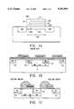
- FIG. 1illustrates the disclosed flash EEPROM cell.
- the flash EEPROM cellcomprises N+ source region 11a and N+/N- drain region 11b separated by channel region 12.
- Channel region 12consists of a portion 12a beneath the floating gate 13 and a portion 12b beneath the select gate 14.
- gate dielectric 16aon which is formed the floating gate 13 and the select gate 14.
- insulation 16btypically a composition layer of thermally grown oxide, deposited silicon nitride, and thermally grown oxide and nitride.
- a control gate 17is formed on top of the insulation 16b. Typically both the floating gate 13 and the control gate 17 are formed of polysilicon.
- An insulation 16cis formed on the sidewall of the floating gate 13 and the control gate 17.
- the select gate 14is formed by depositing the third layer of polysilicon and then by etching back the polysilicon to form a polysilicon spacer.
- the programming (high threshold voltage) of the cellis accomplished by raising the control gate to about 17 volts, the select gate to slightly above the threshold voltage of the select gate transistor which is about 1.5 volts, the drain to 5 volts, and the source to ground.
- the channel electronsare accelerated through a potential drop in between the select gate and the floating gate transistors. It is known that the hot electron injection efficiency using this method can be a thousand times higher than the conventional lateral acceleration method. Due to the high programming efficiency, the flash cell can be programmed with a lower drain voltage (5 volts) and with very low programming current (few micro-amperes).
- Erase of the cellis achieved by raising the drain region 11b to 14 volts, grounding the control gate, and opening the source (floating).
- the high erase voltagecan be obtained by using a charge pump technique from a 5 volt power supply. These features allow operation with a single 5 volt power supply.
- the split gate cell as disclosed in the prior artconsists of two transistors which are the floating gate and the select gate. It takes the space of two transistors to form a single memory bit when it is implemented in a memory array. This is a common drawback for conventional split gate structure and imposes a major limitation for implementing a high density memory array.
- the select gateis a polysilicon spacer which is formed by the polysilicon etching-back technique, and the length of the select gate is determined by the combined height of the floating gate and the control gate which is about 0.4 um.
- the select gateis formed of polysilicon and it is very difficult to apply deposited polycide on a polysilicon spacer.
- the select gatecan only run parallel to the control gate.
- the select gatemust be perpendicular to the control gate.
- the flash EEPROM cell in the prior art FIG. 1cannot be implemented in a higher density virtual ground array structure.
- a conventional virtual ground memory array as shown in FIG. 1Bis formed by using the flash EPROM cell as disclosed in the above application.
- the channel length of the select gate transistoris non-self-aligned and is defined by using a photoresist as a bit line mask as shown in FIG. 1C. Due to the mis-alignment between the bit line mask and the stacked floating and control gates, the non-self-aligned select gate channel length is determined by the photoresist to floating gate edge dimensiona 19B and the mis-alignment tolerance (MA).
- the mis-alignment toleranceis in the range of 0.3 to 0.5 um which will be a major limitation for high density memory array.
- the total dimension per memory bitis equal to 18+19A+19B+MA.
- An object of the inventionis a dual-bit split gate flash EEPROM cell structure using one select gate transistor and two floating gate transistors to form two memory bits in one cell.
- Another object of the inventionis a method of making a fully self-aligned split gate flash EEPROM cell structure by using self-aligned etching step to accurately define the channel length of the select gate transistor.
- Still another object of the inventionis a high density dual-bit flash EEPROM array using the dual-bit split gate flash EEPROM cell.
- a feature of the inventionis that in the dual-bit split gate flash EEPROM cell, a single select gate transistor is shared by two adjacent floating gate transistors, i.e., a single select gate transistor is used for two memory bits.
- Another feature of the inventionis that dual-bit split gate flash EEPROM cell, the select gate transistor in the split gate structure is fully self-aligned.
- Still another featureis that in the dual-bit flash EEPROM array, two floating gate transistors are put in-between two bit lines.
- Still another feature of the inventionis that in the dual-bit flash EEPROM cell, the access of one of the two floating gate transistors is through the turn-on of the select gate transistor and the other floating gate transistor.
- Another feature of the inventionis that the select transistor in the split gate structure is fully self-aligned.
- the present inventionrelates to a high density flash EEPROM cell which is made by a triple-polysilicon process with a split gate structure and four terminals (control gate, select gate, drain and source) wherein one select gate transistor is shared by two floating gate transistors.
- a split gate structuredisclosed in the prior art and the conventional split gate virtual ground array as disclosed in the co-pending application in which each floating gate transistor needs one select gate transistor the dual-bit split gate cell needs only half of the select gate transistor for each floating gate transistor.
- the channel length of the select gate transistor in the dual-bit split gate cellis accurately defined and is fully self-aligned by the separation of two floating gate transistors which is formed by self-aligned polysilicon etching step.
- a high density 5 volt virtual ground flash EEPROM cellis fabricated using the triple polysilicon process with a split gate structure and the four terminals (control gate, select gate, drain and source) for each cell.
- One select transistoris shared by two floating gate transistor cells.
- the channel length of the select transistoris fully aligned with the floating gate transistors and is defined in a self-alignment etching process in forming the control gate and floating gate for each of the two floating gate transistors.
- the select gateruns perpendicular to the bit lines as required in a virtual ground flash EEPROM.
- the select gatecan have a polycide layer formed thereon to reduce resistance and RC delay of a word line.
- FIG. 1Ais a section view of a triple polysilicon EEPROM cell in accordance with the prior art
- FIGS. 1B and 1Care section views of a triple polysilicon flash EPROM device in accordance with our co-pending application.
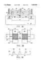
- FIG. 2A, 2B, and 2Care a section view, plan view, and electrical schematic of a triple polysilicon EEPROM cell in accordance with one embodiment of the present invention.
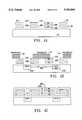
- FIG. 3is plan view of a portion of a memory array using the EEPROM cells of FIGS. 2A-2C.
- FIGS. 4A-4Care section view illustrating steps in fabricating the cell structure of FIGS. 2A-2C.
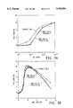
- FIG. 5Ais a plot of transistor threshold voltage versus programming time for the two cell structure of the invention.
- FIG. 5Bis a plot of threshold voltage versus select gate voltage in programming the cell structure of the invention.
- FIG. 6is a plot of control gate voltage versus read current for the cell structure of the invention.
- FIG. 7is a plot of transistor threshold voltage versus erase time in erasing a cell of the structure of the invention.
- FIGS. 2A, 2B, and 2Care a section view, top plan view, and schematic of a dual-bit flash EEPROM cell in accordance with one embodiment of the invention.
- the cell structurecomprises a first floating gate storage transistor 20, a second floating gate storage transistor 22, and a select gate transistor 24 which serially connects transistors 20, 22.
- a first bit line BL1is connected to the drain of transistor 20
- a second bit line BL2is connected the drain of transistor 22, and the sources of the two transistors are serially connected through the select gate 24.
- transistors 22 and 24are turned on and the drain of transistor 22 in effect becomes the source of transistor 20.
- transistors 20 and 24are turned on and the drain of transistor 20 effectively becomes the source of transistor 22.
- the cell structureis formed in a P+ doped substrate 26 with the drain 20a of transistor 20 and the drain 22a of transistor 22 comprising N+/N- doped regions in the surface of the substrate 26.
- the drainsare interconnected with drains in common rows of transistors and form the cell bit lines.
- Transistor 20includes a floating gate 20b and an overlying control gate 20c with the floating gate 20b separated from the surface of substrate 26 by a thin (e.g. 100 angstrom) gate oxide 20d, and the control gate 20c separated from the floating gate 20b by a dielectric 20e which can comprise silicon oxide, silicon nitride, or combination thereof.
- transistor 22includes a floating gate 22b, a control gate 22c, with dielectrics 22d and 22e electrically isolating the floating gate and control gate from each other and from the substrate.
- Dielectric 20f and 22fform part of a dielectric layer overlying the control gates and the surface of substrate 26.
- a word line 28extends over the dielectric layer and forms the control gate 24a of the select transistor intermediate the floating gate transistors 20, 22.
- the word line 28serially connects the gates of the select transistors in one row of a memory array and runs perpendicular to the bit lines connected to the drains of transistors in columns such as drains 20a and 22a as illustrated in the plan view of a portion of a flash EEPROM array shown in FIG. 3.
- FIG. 2Ashows the section view of the present invention in which a dual-bit split gate flash EEPROM cell contains two memory bits.
- the dual-bit split gate cellneeds only half of the select gate transistor for each floating gate transistor.
- the channel length of the select gate transistor in the dual-bit split gate cellis accurately defined and is fully self-aligned by the separation of two floating gate transistors which is formed by self-aligned polysilicon etching step. As shown in FIG.
- each memory bitconsists of one half of diffusion 20A one floating gate length 20G, and one half of the select gate length 24G such that the total dimension of one memory bit is equal to half of 20A-20G+half of 24G.
- the half select gate for each memory bit and the fully self-alignment of the select gate channel length featuresmake the dual-bit split gate most scaleable for ultra high density memory array in the application such as solid-state-disk-drive and IC memory card.
- the select gatecan be implemented by using polycide to reduce the work line RC delay.
- FIGS. 2A-2ACFabrication of the cell structure of FIGS. 2A-2AC is illustrated in the section views of FIGS. 4A-4C. Like elements have the same reference numeral.
- a first layer of doped polysiliconis then deposited on top of the thin oxide and is patterned in one direction to partially form the floating gate layer.
- An insulation layer of silicon oxide, silicon nitride, or combination thereofis then formed on top of the floating gate layer, and a second doped polysilicon layer is then deposited and patterned in one direction for the control gates.
- the double polysilicon stackis etched to form the control gates 20c, 22c and the floating gates 20b, 22b which are self-aligned, as indicated, with insulation therebetween. Similar structures are formed for adjacent transistors are illustrated at 30 and 32.
- a photoresist layer 34is formed and patterned to partially cover one portion of the double polysilicon stack, and an ion implantation step forms the bit line regions 20a and 22a.
- an ion implantation stepforms the bit line regions 20a and 22a.
- the photoresistis stripped, and a silicon oxide insulation layer is formed on the top and side walls of the double polysilicon stacks.
- a third layer of doped polysiliconis then deposited and patterned to form a word line and the select gate 24 as shown in FIG. 4C.
- the word lineis perpendicular to the control gates and runs to adjacent select gates along the word line.
- the select gateis accurately defined by the separation of the two floating gate transistors which are formed by the self-aligned etching step.
- the channel length of the select transistoris about 0.6 to 0.8 micron and is fully aligned with the floating gate transistors.
- the select transistor channel 24gis positioned between the channels 20g and 22g of the floating gate transistor 20 and 22, respectively, as shown in FIGS. 2A.
- a polycide coatingcan be applied on the select gate and word line to reduce the word line RC delay.
- the flash EEPROM cellcan be implemented in a high density virtual ground array.
- Programming of the floating gate transistor 20is achieved by raising the control gates 20c and 22c to 12 volts, the select gate 24a to slightly above the threshold voltage of the select gate transistor (approximately 2 volts) the bit line (drain) 20a to 5 volts, and the bit line (drain) 22a is grounded.
- the floating gate transistorsare fully turned on due to the 12 volts on the control gates and the select gate transistor being slightly turned on. Under this condition channel current during programming is controlled by the select gate transistor and is in the range of 10-20 microamps.
- the channel electronsare accelerated at the potential drop between the select gate region 24g and the floating gate region 20a and are injected into the floating gate 20b through the barrier of the thin gate oxide 20d by hot electron injection.
- a read operation of the floating gate transistor 20is achieved by putting 12 volts on the control gate of transistor 22 to turn on the transistor 22, 5 volts on select gate 24 and control gate 20c, 1-2 volts on bit line 20a, and grounding bit line 22a.
- the back bias effect from floating gate transistor 22is about 0.17 to 0.24 volt when its threshold voltage is -0.25 and 6.6 respectively.
- the erase operation of the floating gate transistor 20is achieved by raising the bit line 20a to 12 volts, grounding the control gates 20c and 22c, and opening the bit line 22a. Electrons are discharged from the floating gate 20b to the bit line 20a through Fowler-Nordheim tunneling effect.
- FIG. 5Ais a plot illustrating threshold voltage change during programming versus programming time, and it will be noted that the threshold voltage of a transistor can be changed by more than 4.5 volts in less than 10 micro seconds.
- FIG. 5Bis a plot illustrating the effect of select gate voltage, VSG on the programming of one floating gate transistor using 10 microsecond pulses. It can been seen that there is very little difference when the other floating gate transistor is at a high or low threshold voltage state.
- FIG. 6is a plot of control gate voltage versus the read current when the floating gate transistors are at a high or low threshold voltage state.
- FIG. 7is a plot illustrating erase time versus threshold voltage for a transistor during an erase operation.
- the cellcan be erased to zero threshold voltage in about 100 milliseconds.
Landscapes
- Engineering & Computer Science (AREA)
- Microelectronics & Electronic Packaging (AREA)
- Computer Hardware Design (AREA)
- Non-Volatile Memory (AREA)
- Semiconductor Memories (AREA)
Abstract
Description
______________________________________ READ CELL 1PROGRAM CELL 1 ERASECELL 1 ______________________________________ V.sub.sg 5 1.8˜2 0V.sub.cg1 5 12 0 V.sub.cg2 12 12 0V.sub.BL1 1˜2 5 12V.sub.BL2 0 0 floating ______________________________________
Claims (3)
Priority Applications (9)
| Application Number | Priority Date | Filing Date | Title |
|---|---|---|---|
| US08/134,779US5364806A (en) | 1991-08-29 | 1993-10-12 | Method of making a self-aligned dual-bit split gate (DSG) flash EEPROM cell |
| DE69432568TDE69432568T2 (en) | 1991-08-29 | 1994-01-11 | SELF-ADJUSTING FLASH EEPROM CELL WITH DOUBLE BIT-DIVIDED GAT |
| ES94906603TES2197905T3 (en) | 1991-08-29 | 1994-01-11 | EEPROM MEMORY CELL FLASH DOOR DIVIDED DOUBLE BIT (DSG) SELF-ALIGNED. |
| PCT/US1994/000407WO1995019047A1 (en) | 1991-08-29 | 1994-01-11 | A self-aligned dual-bit split gate (dsg) flash eeprom cell |
| AT94906603TATE238609T1 (en) | 1991-08-29 | 1994-01-11 | SELF-ADJUSTING FLASH EEPROM CELL WITH DOUBLE-BIT SPLIT GAT |
| JP51845095AJP3720358B2 (en) | 1991-08-29 | 1994-01-11 | Self-aligned dual bit split gate flash EEPROM cell |
| DK94906603TDK0740854T3 (en) | 1991-08-29 | 1994-01-11 | Automatically adjusted dual-bit split gate (DSG) flash EEPROM cell |
| EP94906603AEP0740854B1 (en) | 1991-08-29 | 1994-01-11 | A self-aligned dual-bit split gate (dsg) flash eeprom cell |
| US08/269,972US5414693A (en) | 1991-08-29 | 1994-07-01 | Self-aligned dual-bit split gate (DSG) flash EEPROM cell |
Applications Claiming Priority (3)
| Application Number | Priority Date | Filing Date | Title |
|---|---|---|---|
| US07/751,499US5278439A (en) | 1991-08-29 | 1991-08-29 | Self-aligned dual-bit split gate (DSG) flash EEPROM cell |
| US08/134,779US5364806A (en) | 1991-08-29 | 1993-10-12 | Method of making a self-aligned dual-bit split gate (DSG) flash EEPROM cell |
| PCT/US1994/000407WO1995019047A1 (en) | 1991-08-29 | 1994-01-11 | A self-aligned dual-bit split gate (dsg) flash eeprom cell |
Related Parent Applications (1)
| Application Number | Title | Priority Date | Filing Date |
|---|---|---|---|
| US07/751,499DivisionUS5278439A (en) | 1991-08-29 | 1991-08-29 | Self-aligned dual-bit split gate (DSG) flash EEPROM cell |
Related Child Applications (1)
| Application Number | Title | Priority Date | Filing Date |
|---|---|---|---|
| US08/269,972DivisionUS5414693A (en) | 1991-08-29 | 1994-07-01 | Self-aligned dual-bit split gate (DSG) flash EEPROM cell |
Publications (1)
| Publication Number | Publication Date |
|---|---|
| US5364806Atrue US5364806A (en) | 1994-11-15 |
Family
ID=46247573
Family Applications (1)
| Application Number | Title | Priority Date | Filing Date |
|---|---|---|---|
| US08/134,779Expired - LifetimeUS5364806A (en) | 1991-08-29 | 1993-10-12 | Method of making a self-aligned dual-bit split gate (DSG) flash EEPROM cell |
Country Status (1)
| Country | Link |
|---|---|
| US (1) | US5364806A (en) |
Cited By (56)
| Publication number | Priority date | Publication date | Assignee | Title |
|---|---|---|---|---|
| US5445983A (en)* | 1994-10-11 | 1995-08-29 | United Microelectronics Corporation | Method of manufacturing EEPROM memory device with a select gate |
| US5480819A (en)* | 1994-07-15 | 1996-01-02 | United Microelectronics Corporation | Method of manufacture of high coupling ratio flash memory cell |
| US5480821A (en)* | 1992-09-08 | 1996-01-02 | National Semiconductor Corporation | Method of fabricating source-coupling, split-gate, virtual ground flash EEPROM array |
| US5482881A (en)* | 1995-03-14 | 1996-01-09 | Advanced Micro Devices, Inc. | Method of making flash EEPROM memory with reduced column leakage current |
| GB2293269A (en)* | 1994-09-13 | 1996-03-20 | Hyundai Electronics Ind | Method of manufacturing a nonvolatile memory device |
| GB2293688A (en)* | 1994-09-27 | 1996-04-03 | Hyundai Electronics Ind | Manufacturing flash EEPROM cells |
| US5597751A (en)* | 1995-12-20 | 1997-01-28 | Winbond Electronics Corp. | Single-side oxide sealed salicide process for EPROMs |
| US5686321A (en)* | 1994-07-15 | 1997-11-11 | United Microelectronics Corp. | Local punchthrough stop for ultra large scale integration devices |
| US5714412A (en)* | 1996-12-02 | 1998-02-03 | Taiwan Semiconductor Manufacturing Company, Ltd | Multi-level, split-gate, flash memory cell and method of manufacture thereof |
| US5807787A (en)* | 1996-12-02 | 1998-09-15 | Taiwan Semiconductor Manufacturing Company, Ltd. | Method for reducing surface leakage current on semiconductor intergrated circuits during polyimide passivation |
| US5834808A (en)* | 1995-10-16 | 1998-11-10 | Nec Corporation | Non-volatile semiconductor memory device |
| US5838617A (en)* | 1995-05-25 | 1998-11-17 | Lucent Technologies Inc. | Method for changing electrically programmable read-only memory devices |
| US5856223A (en)* | 1997-02-25 | 1999-01-05 | Winbond Electronics Corp. | Method for manufacturing self-aligned split-gate flash memory cells |
| US5891775A (en)* | 1994-09-29 | 1999-04-06 | Nec Corporation | Method of making nonvolatile semiconductor device having sidewall split gate for compensating for over-erasing operation |
| US6011722A (en)* | 1998-10-13 | 2000-01-04 | Lucent Technologies Inc. | Method for erasing and programming memory devices |
| US6091633A (en)* | 1999-08-09 | 2000-07-18 | Sandisk Corporation | Memory array architecture utilizing global bit lines shared by multiple cells |
| US6103573A (en)* | 1999-06-30 | 2000-08-15 | Sandisk Corporation | Processing techniques for making a dual floating gate EEPROM cell array |
| US6151248A (en)* | 1999-06-30 | 2000-11-21 | Sandisk Corporation | Dual floating gate EEPROM cell array with steering gates shared by adjacent cells |
| US6245614B1 (en)* | 2000-06-19 | 2001-06-12 | United Microelectronics Corp. | Method of manufacturing a split-gate flash memory cell with polysilicon spacers |
| US6245685B1 (en) | 1999-09-01 | 2001-06-12 | Taiwan Semiconductor Manufacturing Company | Method for forming a square oxide structure or a square floating gate structure without rounding effect |
| US6255205B1 (en) | 1997-08-06 | 2001-07-03 | Mosel Vitelic, Inc. | High density programmable read-only memory employing double-wall spacers |
| US6281545B1 (en) | 1997-11-20 | 2001-08-28 | Taiwan Semiconductor Manufacturing Company | Multi-level, split-gate, flash memory cell |
| CN1070642C (en)* | 1995-09-14 | 2001-09-05 | 日本电气株式会社 | Semiconductor memory device and its producing method |
| US6426896B1 (en) | 2000-05-22 | 2002-07-30 | Actrans System Inc. | Flash memory cell with contactless bit line, and process of fabrication |
| US6438027B1 (en)* | 1999-10-07 | 2002-08-20 | Hyundai Electronic Industries Co., Ltd. | Nonvolatile memory, cell array thereof, and method for sensing data therefrom |
| US6462375B1 (en) | 2002-04-01 | 2002-10-08 | Silicon Based Technology Corp. | Scalable dual-bit flash memory cell and its contactless flash memory array |
| US6501680B1 (en) | 1999-10-07 | 2002-12-31 | Hyundai Electronics Industries Co., Ltd. | Nonvolatile memory, cell array thereof, and method for sensing data therefrom |
| US6512263B1 (en) | 2000-09-22 | 2003-01-28 | Sandisk Corporation | Non-volatile memory cell array having discontinuous source and drain diffusions contacted by continuous bit line conductors and methods of forming |
| US20030052360A1 (en)* | 1992-01-14 | 2003-03-20 | Guterman Daniel C. | EEPROM with split gate source side injection with sidewall spacers |
| US6605840B1 (en) | 2002-02-07 | 2003-08-12 | Ching-Yuan Wu | Scalable multi-bit flash memory cell and its memory array |
| US6627927B2 (en)* | 2002-01-30 | 2003-09-30 | Ching-Yuan Wu | Dual-bit flash memory cells for forming high-density memory arrays |
| US20030203575A1 (en)* | 2002-04-29 | 2003-10-30 | Powerchip Semiconductor Corp. | Single-poly eprom and method for forming the same |
| US6674121B2 (en) | 2001-12-14 | 2004-01-06 | The Regents Of The University Of California | Method and system for molecular charge storage field effect transistor |
| US6690058B2 (en) | 2002-04-10 | 2004-02-10 | Ching-Yuan Wu | Self-aligned multi-bit flash memory cell and its contactless flash memory array |
| US6747896B2 (en) | 2002-05-06 | 2004-06-08 | Multi Level Memory Technology | Bi-directional floating gate nonvolatile memory |
| US20040169219A1 (en)* | 2003-01-07 | 2004-09-02 | Takashi Miida | Transistor storing multiple bits and method of manufacturing semiconductor memory including the same |
| US6818512B1 (en)* | 2002-01-04 | 2004-11-16 | Taiwan Semiconductor Manufacturing Company | Split-gate flash with source/drain multi-sharing |
| KR100474626B1 (en)* | 2001-05-11 | 2005-03-08 | 세이코 엡슨 가부시키가이샤 | Method for programming non-volatile semiconductor memory device |
| US6914820B1 (en) | 2002-05-06 | 2005-07-05 | Multi Level Memory Technology | Erasing storage nodes in a bi-directional nonvolatile memory cell |
| US20050162884A1 (en)* | 2003-12-31 | 2005-07-28 | Dongbuanam Semiconductor Inc. | Non-volatile memory device |
| US6985386B1 (en)* | 2004-07-08 | 2006-01-10 | National Semiconductor Corporation | Programming method for nonvolatile memory cell |
| US6992927B1 (en)* | 2004-07-08 | 2006-01-31 | National Semiconductor Corporation | Nonvolatile memory cell |
| US7020027B1 (en)* | 2004-07-08 | 2006-03-28 | National Semiconductor Corporation | Programming method for nonvolatile memory cell |
| US20060163642A1 (en)* | 2002-10-24 | 2006-07-27 | Koninklijke Philips Electronics N.V. | Self-aligned 2-bit "double poly cmp" flash memory cell |
| US20060273378A1 (en)* | 2005-05-20 | 2006-12-07 | Feng Gao | Bidirectional split gate nand flash memory structure and array, method of programming, erasing and reading thereof, and method of manufacturing |
| US20070072373A1 (en)* | 2005-04-13 | 2007-03-29 | United Microelectronics Corp. | Fabrication method of an non-volatile memory |
| US20070103985A1 (en)* | 2002-05-06 | 2007-05-10 | Sau Ching Wong | Fabricating bi-directional nonvolatile memory cells |
| US20070127290A1 (en)* | 2000-04-27 | 2007-06-07 | Semiconductor Energy Laboratory Co., Ltd. | Nonvolatile memory and semiconductor device |
| US20070228451A1 (en)* | 2006-03-30 | 2007-10-04 | Catalyst Semiconductor, Inc. | Scalable Electrically Eraseable And Programmable Memory (EEPROM) Cell Array |
| US20080054336A1 (en)* | 2006-09-05 | 2008-03-06 | Georgescu Sorin S | Scalable Electrically Eraseable And Programmable Memory |
| US20080067577A1 (en)* | 2006-09-15 | 2008-03-20 | Ming-Tsong Wang | Multi-trapping layer flash memory cell |
| US20080073689A1 (en)* | 2006-09-22 | 2008-03-27 | Ming-Tsong Wang | Program/erase schemes for floating gate memory cells |
| US20080165582A1 (en)* | 2006-09-05 | 2008-07-10 | Catalyst Semiconductor, Inc. | Scalable Electrically Eraseable And Programmable Memory |
| US8735963B2 (en) | 2008-07-07 | 2014-05-27 | Taiwan Semiconductor Manufacturing Company, Ltd. | Flash memory cells having leakage-inhibition layers |
| US8750041B2 (en) | 2006-09-05 | 2014-06-10 | Semiconductor Components Industries, Llc | Scalable electrically erasable and programmable memory |
| CN108231784A (en)* | 2016-12-12 | 2018-06-29 | 德克萨斯仪器股份有限公司 | Divide the selection gate autoregistration patterning in grid flashing storage unit |
Citations (8)
| Publication number | Priority date | Publication date | Assignee | Title |
|---|---|---|---|---|
| JPS63306672A (en)* | 1987-06-08 | 1988-12-14 | Seiko Instr & Electronics Ltd | Formation of insulating film |
| JPH01300564A (en)* | 1988-05-27 | 1989-12-05 | Seiko Instr Inc | Manufacturing method of semiconductor device |
| JPH0284776A (en)* | 1987-11-02 | 1990-03-26 | Hitachi Ltd | Method for manufacturing semiconductor integrated circuit device |
| JPH0366172A (en)* | 1989-08-04 | 1991-03-20 | Seiko Instr Inc | Manufacture of semiconductor device |
| US5138410A (en)* | 1989-12-11 | 1992-08-11 | Kabushiki Kaisha Toshiba | Nonvolatile semiconductor memory device having tunnel insulating film structure |
| US5160986A (en)* | 1988-12-05 | 1992-11-03 | Sgs-Thomson Microelectronics S.R.L. | Matrix of EPROM memory cells with a tablecloth structure having an improved capacitative ratio and a process for its manufacture |
| US5212541A (en)* | 1991-04-18 | 1993-05-18 | National Semiconductor Corporation | Contactless, 5v, high speed eprom/flash eprom array utilizing cells programmed using source side injection |
| US5225362A (en)* | 1992-06-01 | 1993-07-06 | National Semiconductor Corporation | Method of manufacturing a full feature high density EEPROM cell with poly tunnel spacer |
- 1993
- 1993-10-12USUS08/134,779patent/US5364806A/ennot_activeExpired - Lifetime
Patent Citations (8)
| Publication number | Priority date | Publication date | Assignee | Title |
|---|---|---|---|---|
| JPS63306672A (en)* | 1987-06-08 | 1988-12-14 | Seiko Instr & Electronics Ltd | Formation of insulating film |
| JPH0284776A (en)* | 1987-11-02 | 1990-03-26 | Hitachi Ltd | Method for manufacturing semiconductor integrated circuit device |
| JPH01300564A (en)* | 1988-05-27 | 1989-12-05 | Seiko Instr Inc | Manufacturing method of semiconductor device |
| US5160986A (en)* | 1988-12-05 | 1992-11-03 | Sgs-Thomson Microelectronics S.R.L. | Matrix of EPROM memory cells with a tablecloth structure having an improved capacitative ratio and a process for its manufacture |
| JPH0366172A (en)* | 1989-08-04 | 1991-03-20 | Seiko Instr Inc | Manufacture of semiconductor device |
| US5138410A (en)* | 1989-12-11 | 1992-08-11 | Kabushiki Kaisha Toshiba | Nonvolatile semiconductor memory device having tunnel insulating film structure |
| US5212541A (en)* | 1991-04-18 | 1993-05-18 | National Semiconductor Corporation | Contactless, 5v, high speed eprom/flash eprom array utilizing cells programmed using source side injection |
| US5225362A (en)* | 1992-06-01 | 1993-07-06 | National Semiconductor Corporation | Method of manufacturing a full feature high density EEPROM cell with poly tunnel spacer |
Cited By (104)
| Publication number | Priority date | Publication date | Assignee | Title |
|---|---|---|---|---|
| US6954381B2 (en) | 1992-01-14 | 2005-10-11 | Sandisk Corporation | EEPROM with split gate source side injection with sidewall spacers |
| US20030052360A1 (en)* | 1992-01-14 | 2003-03-20 | Guterman Daniel C. | EEPROM with split gate source side injection with sidewall spacers |
| US5480821A (en)* | 1992-09-08 | 1996-01-02 | National Semiconductor Corporation | Method of fabricating source-coupling, split-gate, virtual ground flash EEPROM array |
| US5841700A (en)* | 1992-09-08 | 1998-11-24 | National Semiconductor Corporation | Source-coupling, split gate, virtual ground flash EEPROM array |
| US5686321A (en)* | 1994-07-15 | 1997-11-11 | United Microelectronics Corp. | Local punchthrough stop for ultra large scale integration devices |
| US5480819A (en)* | 1994-07-15 | 1996-01-02 | United Microelectronics Corporation | Method of manufacture of high coupling ratio flash memory cell |
| US5536668A (en)* | 1994-09-13 | 1996-07-16 | Hyundai Electronics Industries, Co., Ltd. | Method of manufacturing a virtual ground split gate nonvolatile memory device |
| GB2293269B (en)* | 1994-09-13 | 1998-08-12 | Hyundai Electronics Ind | Method of manufacturing a nonvolatile memory device |
| GB2293269A (en)* | 1994-09-13 | 1996-03-20 | Hyundai Electronics Ind | Method of manufacturing a nonvolatile memory device |
| GB2293688A (en)* | 1994-09-27 | 1996-04-03 | Hyundai Electronics Ind | Manufacturing flash EEPROM cells |
| GB2293688B (en)* | 1994-09-27 | 1998-07-22 | Hyundai Electronics Ind | Method of manufacturing flash eeprom cells |
| US5891775A (en)* | 1994-09-29 | 1999-04-06 | Nec Corporation | Method of making nonvolatile semiconductor device having sidewall split gate for compensating for over-erasing operation |
| US5445983A (en)* | 1994-10-11 | 1995-08-29 | United Microelectronics Corporation | Method of manufacturing EEPROM memory device with a select gate |
| US5482881A (en)* | 1995-03-14 | 1996-01-09 | Advanced Micro Devices, Inc. | Method of making flash EEPROM memory with reduced column leakage current |
| US5838617A (en)* | 1995-05-25 | 1998-11-17 | Lucent Technologies Inc. | Method for changing electrically programmable read-only memory devices |
| CN1070642C (en)* | 1995-09-14 | 2001-09-05 | 日本电气株式会社 | Semiconductor memory device and its producing method |
| US5834808A (en)* | 1995-10-16 | 1998-11-10 | Nec Corporation | Non-volatile semiconductor memory device |
| CN1073285C (en)* | 1995-10-16 | 2001-10-17 | 日本电气株式会社 | Non-volatile semiconductor memory device |
| US5597751A (en)* | 1995-12-20 | 1997-01-28 | Winbond Electronics Corp. | Single-side oxide sealed salicide process for EPROMs |
| US7449746B2 (en) | 1996-02-28 | 2008-11-11 | Sandisk Corporation | EEPROM with split gate source side injection |
| US6664587B2 (en) | 1996-02-28 | 2003-12-16 | Sandisk Corporation | EEPROM cell array structure with specific floating gate shape |
| US6861700B2 (en) | 1996-02-28 | 2005-03-01 | Sandisk Corporation | Eeprom with split gate source side injection |
| US7071060B1 (en) | 1996-02-28 | 2006-07-04 | Sandisk Corporation | EEPROM with split gate source side infection with sidewall spacers |
| US6704222B2 (en) | 1996-02-28 | 2004-03-09 | Sandisk Corporation | Multi-state operation of dual floating gate array |
| US5807787A (en)* | 1996-12-02 | 1998-09-15 | Taiwan Semiconductor Manufacturing Company, Ltd. | Method for reducing surface leakage current on semiconductor intergrated circuits during polyimide passivation |
| US5714412A (en)* | 1996-12-02 | 1998-02-03 | Taiwan Semiconductor Manufacturing Company, Ltd | Multi-level, split-gate, flash memory cell and method of manufacture thereof |
| US5877523A (en)* | 1996-12-02 | 1999-03-02 | Taiwan Semiconductor Manufacturing Company, Ltd. | Multi-level split- gate flash memory cell |
| US5856223A (en)* | 1997-02-25 | 1999-01-05 | Winbond Electronics Corp. | Method for manufacturing self-aligned split-gate flash memory cells |
| US6255205B1 (en) | 1997-08-06 | 2001-07-03 | Mosel Vitelic, Inc. | High density programmable read-only memory employing double-wall spacers |
| US6281545B1 (en) | 1997-11-20 | 2001-08-28 | Taiwan Semiconductor Manufacturing Company | Multi-level, split-gate, flash memory cell |
| US6011722A (en)* | 1998-10-13 | 2000-01-04 | Lucent Technologies Inc. | Method for erasing and programming memory devices |
| US6344993B1 (en) | 1999-06-30 | 2002-02-05 | Sandisk Corporation | Dual floating gate EEPROM cell array with steering gates shared by adjacent cells |
| US6420231B1 (en) | 1999-06-30 | 2002-07-16 | Sandisk Corporation | Processing techniques for making a dual floating gate EEPROM cell array |
| US6266278B1 (en) | 1999-06-30 | 2001-07-24 | Sandisk Corporation | Dual floating gate EEPROM cell array with steering gates shared adjacent cells |
| US6151248A (en)* | 1999-06-30 | 2000-11-21 | Sandisk Corporation | Dual floating gate EEPROM cell array with steering gates shared by adjacent cells |
| US6103573A (en)* | 1999-06-30 | 2000-08-15 | Sandisk Corporation | Processing techniques for making a dual floating gate EEPROM cell array |
| US6091633A (en)* | 1999-08-09 | 2000-07-18 | Sandisk Corporation | Memory array architecture utilizing global bit lines shared by multiple cells |
| US6245685B1 (en) | 1999-09-01 | 2001-06-12 | Taiwan Semiconductor Manufacturing Company | Method for forming a square oxide structure or a square floating gate structure without rounding effect |
| US6438027B1 (en)* | 1999-10-07 | 2002-08-20 | Hyundai Electronic Industries Co., Ltd. | Nonvolatile memory, cell array thereof, and method for sensing data therefrom |
| US6501680B1 (en) | 1999-10-07 | 2002-12-31 | Hyundai Electronics Industries Co., Ltd. | Nonvolatile memory, cell array thereof, and method for sensing data therefrom |
| US8391060B2 (en) | 2000-04-27 | 2013-03-05 | Semiconductor Energy Laboratory Co., Ltd. | Nonvolatile memory and semiconductor device |
| US20070127290A1 (en)* | 2000-04-27 | 2007-06-07 | Semiconductor Energy Laboratory Co., Ltd. | Nonvolatile memory and semiconductor device |
| US6503785B2 (en) | 2000-05-22 | 2003-01-07 | Actrans System Inc. | Flash memory cell with contactless bit line, and process of fabrication |
| US6426896B1 (en) | 2000-05-22 | 2002-07-30 | Actrans System Inc. | Flash memory cell with contactless bit line, and process of fabrication |
| US6245614B1 (en)* | 2000-06-19 | 2001-06-12 | United Microelectronics Corp. | Method of manufacturing a split-gate flash memory cell with polysilicon spacers |
| US7288455B2 (en) | 2000-09-22 | 2007-10-30 | Sandisk Corporation | Method of forming non-volatile memory cell array having discontinuous source and drain diffusions contacted by continuous bit line conductors |
| US7541237B2 (en) | 2000-09-22 | 2009-06-02 | Sandisk Corporation | Non-volatile memory cell array having discontinuous source and drain diffusions contacted by continuous bit line conductors and methods of forming |
| US6512263B1 (en) | 2000-09-22 | 2003-01-28 | Sandisk Corporation | Non-volatile memory cell array having discontinuous source and drain diffusions contacted by continuous bit line conductors and methods of forming |
| US20060007767A1 (en)* | 2000-09-22 | 2006-01-12 | Yuan Jack H | Non-volatile memory cell array having discontinuous source and drain diffusions contacted by continuous bit line conductors and methods of forming |
| US6723604B2 (en) | 2000-09-22 | 2004-04-20 | Sandisk Corporation | Non-volatile memory cell array having discontinuous source and drain diffusions contacted by continuous bit line conductors and methods of forming |
| US6953964B2 (en) | 2000-09-22 | 2005-10-11 | Sandisk Corporation | Non-volatile memory cell array having discontinuous source and drain diffusions contacted by continuous bit line conductors and methods of forming |
| US20040190333A1 (en)* | 2000-09-22 | 2004-09-30 | Yuan Jack H. | Non-volatile memory cell array having discontinuous source and drain diffusions contacted by continuous bit line conductors and methods of forming |
| KR100474626B1 (en)* | 2001-05-11 | 2005-03-08 | 세이코 엡슨 가부시키가이샤 | Method for programming non-volatile semiconductor memory device |
| US6674121B2 (en) | 2001-12-14 | 2004-01-06 | The Regents Of The University Of California | Method and system for molecular charge storage field effect transistor |
| US20050062097A1 (en)* | 2001-12-14 | 2005-03-24 | Veena Misra | Method and system for molecular charge storage field effect transistor |
| US6818512B1 (en)* | 2002-01-04 | 2004-11-16 | Taiwan Semiconductor Manufacturing Company | Split-gate flash with source/drain multi-sharing |
| US20050012135A1 (en)* | 2002-01-04 | 2005-01-20 | Chia-Ta Hsieh | Split-gate flash with source/drain multi-sharing |
| US6627927B2 (en)* | 2002-01-30 | 2003-09-30 | Ching-Yuan Wu | Dual-bit flash memory cells for forming high-density memory arrays |
| US6605840B1 (en) | 2002-02-07 | 2003-08-12 | Ching-Yuan Wu | Scalable multi-bit flash memory cell and its memory array |
| US6462375B1 (en) | 2002-04-01 | 2002-10-08 | Silicon Based Technology Corp. | Scalable dual-bit flash memory cell and its contactless flash memory array |
| US6690058B2 (en) | 2002-04-10 | 2004-02-10 | Ching-Yuan Wu | Self-aligned multi-bit flash memory cell and its contactless flash memory array |
| US20030203575A1 (en)* | 2002-04-29 | 2003-10-30 | Powerchip Semiconductor Corp. | Single-poly eprom and method for forming the same |
| US6917070B2 (en) | 2002-04-29 | 2005-07-12 | Powerchip Semiconductor Corp. | Single-poly EPROM and method for forming the same |
| US6653183B2 (en)* | 2002-04-29 | 2003-11-25 | Powerchip Semiconductor Corp. | Single-poly EPROM and method for forming the same |
| US20040053467A1 (en)* | 2002-04-29 | 2004-03-18 | Powerchip Semiconductor Corp. | Single-poly eprom and method for forming the same |
| US20070103985A1 (en)* | 2002-05-06 | 2007-05-10 | Sau Ching Wong | Fabricating bi-directional nonvolatile memory cells |
| US7221591B1 (en) | 2002-05-06 | 2007-05-22 | Samsung Electronics Co., Ltd. | Fabricating bi-directional nonvolatile memory cells |
| US7355891B2 (en) | 2002-05-06 | 2008-04-08 | Samsung Electronics Co., Ltd. | Fabricating bi-directional nonvolatile memory cells |
| US6914820B1 (en) | 2002-05-06 | 2005-07-05 | Multi Level Memory Technology | Erasing storage nodes in a bi-directional nonvolatile memory cell |
| US6747896B2 (en) | 2002-05-06 | 2004-06-08 | Multi Level Memory Technology | Bi-directional floating gate nonvolatile memory |
| US6826084B1 (en) | 2002-05-06 | 2004-11-30 | Multi Level Memory Technology | Accessing individual storage nodes in a bi-directional nonvolatile memory cell |
| US7214579B2 (en)* | 2002-10-24 | 2007-05-08 | Nxp Bv. | Self-aligned 2-bit “double poly CMP” flash memory cell |
| US20060163642A1 (en)* | 2002-10-24 | 2006-07-27 | Koninklijke Philips Electronics N.V. | Self-aligned 2-bit "double poly cmp" flash memory cell |
| US20040169219A1 (en)* | 2003-01-07 | 2004-09-02 | Takashi Miida | Transistor storing multiple bits and method of manufacturing semiconductor memory including the same |
| US7177185B2 (en)* | 2003-12-31 | 2007-02-13 | Dongbu Electronics Co., Ltd. | Non-volatile flash memory device having dual-bit floating gate |
| US20050162884A1 (en)* | 2003-12-31 | 2005-07-28 | Dongbuanam Semiconductor Inc. | Non-volatile memory device |
| US6985386B1 (en)* | 2004-07-08 | 2006-01-10 | National Semiconductor Corporation | Programming method for nonvolatile memory cell |
| US7020027B1 (en)* | 2004-07-08 | 2006-03-28 | National Semiconductor Corporation | Programming method for nonvolatile memory cell |
| US6992927B1 (en)* | 2004-07-08 | 2006-01-31 | National Semiconductor Corporation | Nonvolatile memory cell |
| US7485533B2 (en)* | 2005-04-13 | 2009-02-03 | United Microelectronics Corp. | Fabrication method of an non-volatile memory |
| US20070072373A1 (en)* | 2005-04-13 | 2007-03-29 | United Microelectronics Corp. | Fabrication method of an non-volatile memory |
| US20070020853A1 (en)* | 2005-05-20 | 2007-01-25 | Silicon Storage Technology, Inc. | Bidirectional split gate NAND flash memory structure and array, method of programming, erasing and reading thereof, and method of manufacturing |
| US7544569B2 (en)* | 2005-05-20 | 2009-06-09 | Silicon Storage Technology, Inc. | Bidirectional split gate NAND flash memory structure and array, method of programming, erasing and reading thereof, and method of manufacturing |
| US7247907B2 (en)* | 2005-05-20 | 2007-07-24 | Silicon Storage Technology, Inc. | Bidirectional split gate NAND flash memory structure and array, method of programming, erasing and reading thereof, and method of manufacturing |
| US20060273378A1 (en)* | 2005-05-20 | 2006-12-07 | Feng Gao | Bidirectional split gate nand flash memory structure and array, method of programming, erasing and reading thereof, and method of manufacturing |
| US20090196105A1 (en)* | 2006-03-30 | 2009-08-06 | Catalyst Semiconductor, Inc. | Scalable Electrically Eraseable And Programmable Memory (EEPROM) Cell Array |
| US7547944B2 (en) | 2006-03-30 | 2009-06-16 | Catalyst Semiconductor, Inc. | Scalable electrically eraseable and programmable memory (EEPROM) cell array |
| US20070228451A1 (en)* | 2006-03-30 | 2007-10-04 | Catalyst Semiconductor, Inc. | Scalable Electrically Eraseable And Programmable Memory (EEPROM) Cell Array |
| US20090135649A1 (en)* | 2006-03-30 | 2009-05-28 | Catalyst Semiconductor, Inc. | Scalable Electrically Eraseable And Programmable Memory (EEPROM) Cell Array |
| US8093650B2 (en) | 2006-03-30 | 2012-01-10 | Semiconductor Components Industries, L.L.C. | Scalable electrically eraseable and programmable memory (EEPROM) cell array |
| US7920424B2 (en) | 2006-03-30 | 2011-04-05 | Semiconductor Components Industries, L.L.C. | Scalable electrically eraseable and programmable memory (EEPROM) cell array |
| CN101512776B (en)* | 2006-09-05 | 2011-04-27 | 半导体元件工业有限公司 | Scalable EEPROM |
| US20080054336A1 (en)* | 2006-09-05 | 2008-03-06 | Georgescu Sorin S | Scalable Electrically Eraseable And Programmable Memory |
| US20080165582A1 (en)* | 2006-09-05 | 2008-07-10 | Catalyst Semiconductor, Inc. | Scalable Electrically Eraseable And Programmable Memory |
| US8139408B2 (en)* | 2006-09-05 | 2012-03-20 | Semiconductor Components Industries, L.L.C. | Scalable electrically eraseable and programmable memory |
| US7528436B2 (en)* | 2006-09-05 | 2009-05-05 | Catalyst Semiconductor, Inc. | Scalable electrically eraseable and programmable memory |
| US8750041B2 (en) | 2006-09-05 | 2014-06-10 | Semiconductor Components Industries, Llc | Scalable electrically erasable and programmable memory |
| US20080067577A1 (en)* | 2006-09-15 | 2008-03-20 | Ming-Tsong Wang | Multi-trapping layer flash memory cell |
| US8816422B2 (en) | 2006-09-15 | 2014-08-26 | Taiwan Semiconductor Manufacturing Company, Ltd. | Multi-trapping layer flash memory cell |
| US20080073689A1 (en)* | 2006-09-22 | 2008-03-27 | Ming-Tsong Wang | Program/erase schemes for floating gate memory cells |
| US8294197B2 (en)* | 2006-09-22 | 2012-10-23 | Taiwan Semiconductor Manufacturing Company, Ltd. | Program/erase schemes for floating gate memory cells |
| US8735963B2 (en) | 2008-07-07 | 2014-05-27 | Taiwan Semiconductor Manufacturing Company, Ltd. | Flash memory cells having leakage-inhibition layers |
| CN108231784A (en)* | 2016-12-12 | 2018-06-29 | 德克萨斯仪器股份有限公司 | Divide the selection gate autoregistration patterning in grid flashing storage unit |
| CN108231784B (en)* | 2016-12-12 | 2024-05-10 | 德克萨斯仪器股份有限公司 | Select gate self-aligned patterning in split gate flash memory cells |
Similar Documents
| Publication | Publication Date | Title |
|---|---|---|
| US5364806A (en) | Method of making a self-aligned dual-bit split gate (DSG) flash EEPROM cell | |
| US5278439A (en) | Self-aligned dual-bit split gate (DSG) flash EEPROM cell | |
| US5414693A (en) | Self-aligned dual-bit split gate (DSG) flash EEPROM cell | |
| US6885586B2 (en) | Self-aligned split-gate NAND flash memory and fabrication process | |
| US6503785B2 (en) | Flash memory cell with contactless bit line, and process of fabrication | |
| US6248633B1 (en) | Process for making and programming and operating a dual-bit multi-level ballistic MONOS memory | |
| US7274075B2 (en) | Nonvolatile semiconductor memory device having pair of selection transistors with different source and drain impurity concentrations and with different channel dopant concentrations | |
| US6177703B1 (en) | Method and apparatus for producing a single polysilicon flash EEPROM having a select transistor and a floating gate transistor | |
| US5792670A (en) | Method of manufacturing double polysilicon EEPROM cell and access transistor | |
| US6894339B2 (en) | Flash memory with trench select gate and fabrication process | |
| CN100501928C (en) | Method for manufacturing flash memory cells with self-aligned gates | |
| US6058045A (en) | Serial flash memory | |
| US5150179A (en) | Diffusionless source/drain conductor electrically-erasable, electrically-programmable read-only memory and method for making and using the same | |
| US9892790B2 (en) | Method of programming a continuous-channel flash memory device | |
| US5982669A (en) | EPROM and flash memory cells with source-side injection | |
| US6190968B1 (en) | Method for forming EPROM and flash memory cells with source-side injection | |
| US5482879A (en) | Process of fabricating split gate flash memory cell | |
| EP1345273A1 (en) | Dual bit multi-level ballistic monos memory, and manufacturing method, programming, and operation process for the memory | |
| US6573142B1 (en) | Method to fabricate self-aligned source and drain in split gate flash | |
| US5304505A (en) | Process for EEPROM cell structure and architecture with increased capacitance and with programming and erase terminals shared between several cells | |
| US20020055228A1 (en) | Sidewall process to improve the flash memory cell performance | |
| US5057446A (en) | Method of making an EEPROM with improved capacitive coupling between control gate and floating gate | |
| US6627947B1 (en) | Compact single-poly two transistor EEPROM cell | |
| US5604141A (en) | Method for forming virtual-ground flash EPROM array with reduced cell pitch in the X direction | |
| US7145802B2 (en) | Programming and manufacturing method for split gate memory cell |
Legal Events
| Date | Code | Title | Description |
|---|---|---|---|
| AS | Assignment | Owner name:HYUNDAI ELECTRONICS INDUSTRIES CO., LTD., KOREA, R Free format text:ASSIGNMENT OF ASSIGNORS INTEREST;ASSIGNOR:BRIGHT MICROELECTRONICS, INC.;REEL/FRAME:007061/0513 Effective date:19940630 | |
| STCF | Information on status: patent grant | Free format text:PATENTED CASE | |
| FEPP | Fee payment procedure | Free format text:PAYOR NUMBER ASSIGNED (ORIGINAL EVENT CODE: ASPN); ENTITY STATUS OF PATENT OWNER: LARGE ENTITY | |
| FPAY | Fee payment | Year of fee payment:4 | |
| FPAY | Fee payment | Year of fee payment:8 | |
| AS | Assignment | Owner name:BRIGHT MICROELECTRONICS INCORPORATED, CALIFORNIA Free format text:ASSIGNMENT OF ASSIGNORS INTEREST;ASSIGNOR:HYUNDAI ELECTRONICS INDUSTRIES CO., LTD.;REEL/FRAME:013735/0873 Effective date:19981104 Owner name:WINBOND ELECTRONICS CORPORATION, TAIWAN Free format text:ASSIGNMENT OF ASSIGNORS INTEREST;ASSIGNOR:BRIGHT MICROELECTRONICS INCORPORATED;REEL/FRAME:013067/0832 Effective date:20000101 | |
| FPAY | Fee payment | Year of fee payment:12 |