US5364401A - External alignment system for preparing a femur for an implant - Google Patents
External alignment system for preparing a femur for an implantDownload PDFInfo
- Publication number
- US5364401A US5364401AUS07/957,991US95799192AUS5364401AUS 5364401 AUS5364401 AUS 5364401AUS 95799192 AUS95799192 AUS 95799192AUS 5364401 AUS5364401 AUS 5364401A
- Authority
- US
- United States
- Prior art keywords
- bone
- base
- relative
- cut
- single point
- Prior art date
- Legal status (The legal status is an assumption and is not a legal conclusion. Google has not performed a legal analysis and makes no representation as to the accuracy of the status listed.)
- Expired - Fee Related
Links
Images


Classifications
- A—HUMAN NECESSITIES
- A61—MEDICAL OR VETERINARY SCIENCE; HYGIENE
- A61B—DIAGNOSIS; SURGERY; IDENTIFICATION
- A61B17/00—Surgical instruments, devices or methods
- A61B17/16—Instruments for performing osteoclasis; Drills or chisels for bones; Trepans
- A61B17/1662—Instruments for performing osteoclasis; Drills or chisels for bones; Trepans for particular parts of the body
- A61B17/1675—Instruments for performing osteoclasis; Drills or chisels for bones; Trepans for particular parts of the body for the knee
- A—HUMAN NECESSITIES
- A61—MEDICAL OR VETERINARY SCIENCE; HYGIENE
- A61B—DIAGNOSIS; SURGERY; IDENTIFICATION
- A61B17/00—Surgical instruments, devices or methods
- A61B17/14—Surgical saws
- A61B17/15—Guides therefor
- A61B17/154—Guides therefor for preparing bone for knee prosthesis
- A61B17/155—Cutting femur
- A—HUMAN NECESSITIES
- A61—MEDICAL OR VETERINARY SCIENCE; HYGIENE
- A61B—DIAGNOSIS; SURGERY; IDENTIFICATION
- A61B17/00—Surgical instruments, devices or methods
- A61B17/16—Instruments for performing osteoclasis; Drills or chisels for bones; Trepans
- A61B17/1659—Surgical rasps, files, planes, or scrapers
- A—HUMAN NECESSITIES
- A61—MEDICAL OR VETERINARY SCIENCE; HYGIENE
- A61F—FILTERS IMPLANTABLE INTO BLOOD VESSELS; PROSTHESES; DEVICES PROVIDING PATENCY TO, OR PREVENTING COLLAPSING OF, TUBULAR STRUCTURES OF THE BODY, e.g. STENTS; ORTHOPAEDIC, NURSING OR CONTRACEPTIVE DEVICES; FOMENTATION; TREATMENT OR PROTECTION OF EYES OR EARS; BANDAGES, DRESSINGS OR ABSORBENT PADS; FIRST-AID KITS
- A61F2/00—Filters implantable into blood vessels; Prostheses, i.e. artificial substitutes or replacements for parts of the body; Appliances for connecting them with the body; Devices providing patency to, or preventing collapsing of, tubular structures of the body, e.g. stents
- A61F2/02—Prostheses implantable into the body
- A61F2/30—Joints
- A61F2/46—Special tools for implanting artificial joints
Definitions
- the present inventiongenerally relates to knee surgical resection techniques. More particularly, the present invention provides an article and method for preparing a bone, such as a femur, to receive a distal implant.
- the alignment of the total knee componentsis an essential step in the performance of the total knee replacement arthroplasty.
- the present inventionprovides a device and method allowing for accurately cutting the femur to accept femoral prothesis by providing a single point reference device that locates along the long axis of the femur and locks to it for referencing the external device to accurately place the cuts.
- an article for preparing a bone to receive a distal implantcomprising a base having a longitudinal axis and mounting means for mounting the base on the bone aligning the longitudinal axis of the base parallel with a long axis of the bone.
- a single point connecting meansconnects a plurality of bone preparing devices to the base at a single point reference.
- Axial adjustment meansaxially adjust the single point connecting means relative to the longitudinal axis of the base and the long axis of the bone.
- Radial adjustment meansradially adjusts the single point connecting means relative to the base and the distal end of the bone.
- the present inventionfurther provides a method for preparing the distal end of a bone to receive the distal implant, the method generally including the steps of mounting a base member on the bone and clamping the base member along the long axis of the bone.
- One of a plurality of bone preparing devicesare connected to the base member at a single reference point.
- the single reference pointis axially and radially adjusted relative to the base member and long axis of the bone, thereby normalizing the axial and radial orientation of the bone preparing devices relative to the distal end of the bone.
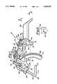
- FIG. 1is perspective view of the base member of the present invention having a distal cutting component mounted thereon;
- FIG. 2is an end on view of the apparatus shown in FIG. 1 taken substantially along lines 2--2 of FIG. 1;
- FIG. 3is a perspective view of the base member having a planing cut component mounted thereon;
- FIG. 4is a perspective view of the base member having a cutting block component mounted thereon;
- FIG. 5is a perspective view of the distal cutting component mounted on the base member of the assembly, the assembly being mounted on the distal end of femur;
- FIG. 6shows the base member having the planing component mounted thereon, the assembly being mounted on the distal end of the femur, the distal end of the femur having a distal cut made thereon;
- FIG. 7is a perspective view of the base member having the cutting block component mounted thereon, the assembly being mounted on the distal end of the femur, the distal end of the femur having been planed as shown in FIG. 6.
- An article for preparing a bone to receive a distal implantis generally shown at 10 in the drawings.
- the article 10 as shownis specifically useful in preparing a femur to receive a distal femoral implant.
- the present inventioncan be modified in size for use in preparing various long bone distal surfaces to receive an implant.
- the article 10includes a base, generally shown at 12, having a longitudinal axis shown by hatch line 14.
- the base 12includes a support member 16 which is L-shaped when viewed from its side and includes a top support surface 18.
- a pair of brackets 20,22are mounted on the support surface 18.
- the first of the brackets 20is axially adjustable relative to the longitudinal axis 14 of the base 12.
- the second of the brackets 22is radially adjustable relative to the base 12.
- the second bracket 22is operatively connected to the support surface 18 and the first of the brackets 20 is connected to the second bracket 22.
- These bracketscould be connected in the reverse fashion wherein the first bracket 20 is designed to be connected to the mounting surface 18 and the second bracket 22 is designed to be connected to the first bracket 20.
- the first bracket 20is slidably supported within a groove track 24 in the second bracket 22.
- a lockscrew mechanism 26fixes or sets the first bracket 20 in a desired position relative to the second bracket 22.
- An indicating line 28 on the top surface of the first bracket 20cooperates with distance markings 30 on an adjoining top surface of the second bracket 22 to indicate the amount of relative axial movement between the first bracket 20 and the second bracket 22 for purposes described in detail below.
- the second bracket 22is pivotally mounted on the top surface 18 of the support member 16 by means well known in the art.
- Lockscrew mechanism 32is disposed within an arcuate slot 34 of the second bracket 22 for setting and fixing a position of the second bracket 22 relative to the support member 16.
- Arm 38extends upwardly from the support bracket 16 functionally. Marking 36 on arm 38 cooperates with markings 39 on the adjoining surface of the second bracket 22 to indicate specifically the relative radial displacement of the second bracket 22 from the zero point, the zero point indicating that the bracket 22 substantially parallel with the longitudinal axis 14 of the base 12.
- the first bracket 20includes a distal mounting surface 40 having a locking mechanism 42 mounted thereon.
- This locking mechanism 42is in the form of a lockscrew.
- each of the locking mechanisms 26,32,42can take other forms well known in the art.
- Each locking mechanismreversibly locks and unlocks the various members associated therewith.
- the locking mechanism 42provides a single point connecting means for connecting a plurality of bone preparing devices, as described below, to the base 12 at a single reference point.
- the first bracket 20provides axial adjustment means for axially adjusting the single point connecting means relative to the longitudinal axis 14 of the base 12 and the long axis of the bone upon which the base 12 is mounted.
- Second bracket 22provides radial adjustment means for radially adjusting the single point connecting means relative to the base 12 and the distal end of the bone.
- the markings 30,39 in cooperation with indicating lines 28,36provide precise quantitative measurement of the axial displacement from the connecting surface or mechanism 42 (and those devices attached thereto) and the zero reference point while indicating reference numerals 39 cooperate with indicating line 36 to quantitatively provide precise radial displacement.
- the use of these mechanismsallow for precise alignment of the bone preparing devices attached to the connecting mechanism 42 externally of the bone such that precise alignment preparation of the bone distal end can be made which translates into more accurate placement of the prosthesis device. This further translates into significantly improved function of the implants.
- the entire base 12remains noninvasive.
- the base 12includes seating means for seating the base 12 on the bone along the long axis of the bone.
- the seating meansincludes two spaced substantially V-shaped surfaces 44 and 46 extending from the bottom surface of the base 12.
- the surfaces 44,46can be made in various shapes to effectively seat the base 12.
- the L-shaped support member 16includes a first leg 48 having the support surface 18 thereon defining a top surface of the base 12.
- the support memberfurther includes a second leg 50 including one of the substantially V-shaped surfaces 44.
- the base 12further includes an arm portion 52 extending from the second leg portion 50, the length of the arm portion 52 defining the longitudinal axis 14 of the base 12.
- the arm portion 52includes a second one of the substantially U-shaped portions 46 distal from the second leg 16.
- the devicecould include further support surfaces to stabilize the device as needed.
- the article 10includes mounting means which can be in the form of a state of the art bone clamp 51, as shown in FIGS. 5 through 7 engaging the arm portion 52 for clamping the arm portion 52 about the bone.
- the bone clamp 51can take on various forms.
- the mounting functionis critical for the function of the device as once the base is appropriately externally mounted (being noninvasive) and the brackets 20,22 are set, the mounting surface 40 becomes a stable landmark for mounting all tool attachments and setting the angle and depth of all cuts made. Accurate cutting of the femur to accept a femoral prosthesis is thereby achieved.
- the devicethereby provides a single point reference device at the locking mechanism 42 which is securely set in place relative to the bone by the mounting means as well as locked axially and radially relative to the distal end of the bone in order to allow for referencing of the external device to accurately place the cuts.
- the present inventionprovides three components herein illustrated in FIGS. 1, 3 and 4.
- a distal cut componentis generally shown at 56.
- the distal cut component 56includes a mounting slot 58 for engagement by the locking mechanism 42 to connect the distal cut component 56 to the mounting surface 40 of the single point connecting means 42.
- the distal cut component 56can be released from the base 16 by loosening of the locking mechanism 42.
- the distal cut component 56includes a body portion 60 and a guide track 62 mounted thereon for guiding a blade of the cutting instrument to make a sagittal cut at the distal end of the bone.
- Such cutting instrumentsare well known in the art.
- L-shaped rod member 64provides referencing means for referencing the guide track 62 vis-a-vis the distal end of the bone to set a zero point reference at a most distal end of the bone. More specifically, the L-shaped rod member 64 includes a first arm 66 pivotally connected to the base portion 60 of the distal cut component. The rod member 64 is connected to an axle 68 which can be fixed from rotation by a ball plunger of a set screw 70. The rod member 64 includes a second arm portion 72 having an end portion 74 which is coplanar with the slot 76 in the guide track 62 which receives the saw blade.
- alignment of the end portion 74 with the distal most surface of the bone to be resectedaligns the guide track 62 with the same distal most surface of the bone defining a zero point reference of the guide track relative to the bone.
- the axial adjustment means comprising the first bracket 20can be adjusted to set an amount of bone cut and the radial adjustment means defined by the bracket 22 is adjusted to set an angle of the cut relative to the long axis of the bone.
- the quantitative mechanisms of the base 12are normalized by the reference rod 64 to the distal most portion of the bone. After this normalization, the distance indicators 30,39 can provide accurate measurements of the amount of bone being cut and the angle of the cut.
- FIG. 3shows a planing component generally shown at 78.
- the planing component 78planes the sagittally cut surface at the distal end of the bone. This is a critical step to achieve close tolerances between the cut bone surface and the base of the implant. When the bone to be cut is the femur, the fit is critical because of the load bearing function of the implant at the distal end of the bone.
- the planing component 78includes a tool holder 80, a planing tool 82 operatively connected thereto, and a locking mechanism receiving slot 84 for receiving the locking mechanism 42 thereby connecting the tool holder at the single point connecting means. Similar to the precise placement of the distal cutting component 56, once the distal cutting component 56 is removed, it is replaced by the tool holder 80 thereby setting the planing tool 82 at the same angle as the previously made distal cut.
- the tool holder 80includes a pocket 86 defining a cylinder channel therethrough.
- the channelis parallel with the longitudinal axis 14 of the base 12.
- the planing tool 82includes a stem having a smaller diameter portion 88 receivable and releasable from the pocket 86 and axially moveable therein and a larger diameter portion 90 retainable within the pocket 86 and axially moveable therein for locking the planing tool 82 in the tool holder 80 at the predetermined radial orientation relative to the base 12.
- the radial adjustment mechanismcan be reset for further radial orientation of the planing tool 82 to the sagittal bone cut surface if desired.
- the planing tool 82includes a handle portion 92 which can be gripped by the operator.
- the planing tool 82also includes a planing surface 94 which planes the previously cut surface.
- Such a planing toolcan take various other forms and be used independent of the distal cutting component previously described.
- a cutting block component mounted on the base 12is generally shown at 96 in FIG. 4.
- the cutting block component 96guides a blade of cutting tool to make cuts on anterior, inferior and posterior surfaces of the distal end of the bone prior to the mounting of the trial prosthesis.
- the cutting block component 96includes a mounting slot 98 for receiving the locking mechanism 42 thereby connecting the cutting block component 96 to the single point connecting means.
- the cutting block component 96includes a connector member 100 for connection to the locking mechanism 42 and a block member 102 including a plurality of slots 104 extending therethrough for receiving a blade of cutting device. Examples of such cutting devices are well known in the art.
- the cutting block 102includes a top portion 106 pivotally connected to the connector member 100 by locking mechanism 108.
- the cutting block component 96further includes a wedge member 110 connected to the bottom portion 112 of the cutting block 102 and having a bottom surface 114 defining a predetermined angle relative to the bottom portion of the block member 102 whereby the angle allows for a predetermined rotation of the cutting block member relative to the connecting member 100 for the purposes described below.
- the assemblyincludes various other pins for securing the device which are described in detail below in relation to the preferred surgical protocol.
- the present inventionprovides a method for preparing the distal end of a bone to receive a distal implant.
- the device shown in the figuresis specifically designed for the preparation of femoral implant.
- the methodincludes the steps of mounting the base member 12 on the bone and clamping the base member 12 along the long axis of the bone.
- One of a plurality of bone preparing devicessuch as those shown in FIGS. 1, 3, and 4, are connected to the base member 12 at a single reference point defined by locking mechanism 42.
- the single reference pointis axially adjusted relative to the base member 12 and the long axis of the bone by adjustment of the first bracket 22 and locking mechanism 26.
- the single reference pointis adjusted radially relative to the base 12 and the distal end of the bone by adjustment of the second bracket 22 and locking mechanism 32.
- This methodnormalizes axial and radial orientation of the bone preparing devices relative to the distal end of the bone.
- the preferred surgical procedureis as follows and illustrated in FIGS. 5 through 7.
- the article 10is placed onto the long axis of the femur as shown in FIG. 5.
- the distal cut component 56is connected .to the base 12.
- the reference lines 28,36are zeroed relative to the guide markings 30,39.
- the second bracket 22is then set for a valgus angle desired by the practitioner in view of the anatomic femur. This is accomplished by loosening the locking screw mechanism 32 and rotating the bracket 22 into the desired position which is located by the indicator set at 0°, 3°, 5° etc.
- the valgus anglecan be set for left or right knees as the indicators go to the left and right of the zero point.
- the member 38can include a ball plunger (not shown) which can lock into grooves 116 in the end of the bracket 22 corresponding to the degree variations marked by indications 39. Once the correct valgus angle desired is set, the lockscrew 32 is tightened down.
- the guide 10is slid back and forth referencing the high point on the condyle of the distal end of the knee. This can also be located by rotating the rod 64 by loosening of the lockscrew 70. This allows the end portion 74 of the rod 64 to slide and rotate to find the correct location of the high point of the condyle. Reference is then made in relationship to the patellar track and intercondylar notch of the femur. Once this is done, the high point of the condyle is then rechecked and the bracket is locked in place by pins disposed through pin holes 118 and by the clamp 51 around the arm portion 52 about the bone.
- the distal cut componenthas been set for a zero amount of bone at the high point of the condyle.
- the amount of bone to be takencan be adjusted by loosening the lockscrew 26 and adjusting the reference indicator 28 to correct amount of bone to be removed in 2 millimeter increments as indicated by reference numerals 30.
- the amount of bone to be taken from the distal surfaceis set by the thickness of the implant distal surface. The depths are 6 millimeters for a - small, + small, medium and medium +, 7 mm for a - large and + large, and 8 mm for an - extra large femoral component as normally used.
- the lockscrew mechanism 42is loosened and the distal cut component is removed along with the rod 64 attached thereto. If the rod member 64 is determined to be cumbersome or in the way, it can be rotated by loosening of the setscrew 70 or completely removed by removal of the axial 68 the base 60.
- planing component 78is slid onto the surface 40 by mating of the slot 84 with the locking screw 42 as shown in FIG. 6.
- the channel 86 of the tool holder 80is set at a location of about the center of the distal cut of the femur. Once this is done, the planing tool 82 is slipped in from the side and slipped forward to engage the larger diameter portion 90 within the pocket 86. This allows for precision planing of the distal surface of the bone and is still accurate in relationship to the single point reference. Once planing is complete, the planing tool 82 and tool holder 80 are removed from the base 12.
- the final procedureis to place the cutting block component 96 onto the locking surface 40 by mating of the slot 98 with the locking screw 42 and tightening the locking screw 42.
- the connecting member 100is slid all the way up along the slot 98 relative to the locking screw 42 in order to visualize the posterior condyles of the tibia.
- the locking screw mechanism 42is then hand tightened to hold it in place while various checks are made.
- the wedge member 110is used to set the external rotation of the cutting block member 102 and is placed in a hole 120 on the top portion 106 of the cutting block member 102.
- the wedgeallows for a setting of 4° of external rotation and is marked left and right such that it can be used for the left or right knee.
- This 4° rotationnormalizes or evens the condyles relative to the cuts that are about to be made and thereby to the prosthesis that will be mounted.
- This adjustmentcorrects the cuts to be made and thereby the placement of the femoral prosthesis to allow for improved patella load bearing characteristics.
- the adjustmentallows for setting of the external rotation required to place the implant accurately and reduce patella tendon forces.
- the instrumentactually utilizes the posterior condyle as a line of site reference to correct set the proper external rotation such that this external rotation, in combination with the axial alignment and valgus alignment already provided by the system in total provides reduced tendon forces on the patella.
- the lockscrew 108is loosened and the block rotated to achieve equal amounts of posterior condyle exposure beneath the bottom surface 114 of the wedge 110. This is achieved by relative movement of the locking screw 108 through slot 124. Once external rotation has been set, the lockscrew is tightened down and the external rotation will remain set in this position.
- a pin 126is placed through the block member 102.
- the locking mechanism screw 42is loosened, allowing the entire cutting block component 96 to slide down until the pin rests in the patella track of the femur. This references the deepest point equal to the edge of the long axis of the femur.
- the locking screw mechanism 42is tightened and the cutting block component 96 is now set in the correct position to make the cuts.
- locking screw mechanism 26is loosened and the cutting block component 96 is slid against the distal surface of the bone.
- the block member 102is pinned in place by pins disposed through pin holes 128, the mounted pins (not shown) providing for decreased vibration of the cutting block member 102 and secured positioning.
- the anterior, posterior, and bevel cutsare then made. Once this is complete, the locking screw mechanism 42 is loosened, the pins removed, and the entire cutting block component 96 is removed for proper trialing of the implant before the base 12 is removed.
- the maintenance of the base 12 in placeis very useful if revision is required. For example, if revision is required, such as the need for posterior stabilization, separate further components can be mounted on the base 12 for the further operations and the cuts can be accurately placed with respect to current cuts.
Landscapes
- Health & Medical Sciences (AREA)
- Surgery (AREA)
- Life Sciences & Earth Sciences (AREA)
- Medical Informatics (AREA)
- Animal Behavior & Ethology (AREA)
- Orthopedic Medicine & Surgery (AREA)
- Oral & Maxillofacial Surgery (AREA)
- Engineering & Computer Science (AREA)
- Biomedical Technology (AREA)
- Heart & Thoracic Surgery (AREA)
- Dentistry (AREA)
- Molecular Biology (AREA)
- Nuclear Medicine, Radiotherapy & Molecular Imaging (AREA)
- General Health & Medical Sciences (AREA)
- Public Health (AREA)
- Veterinary Medicine (AREA)
- Physical Education & Sports Medicine (AREA)
- Transplantation (AREA)
- Surgical Instruments (AREA)
- Prostheses (AREA)
- Radiation-Therapy Devices (AREA)
- Vehicle Body Suspensions (AREA)
Abstract
Description
Claims (15)
Priority Applications (8)
| Application Number | Priority Date | Filing Date | Title |
|---|---|---|---|
| US07/957,991US5364401A (en) | 1992-10-08 | 1992-10-08 | External alignment system for preparing a femur for an implant |
| JP6510134AJPH07501966A (en) | 1992-10-08 | 1993-10-07 | External alignment method |
| DE69324233TDE69324233T2 (en) | 1992-10-08 | 1993-10-07 | EXTERNAL ALIGNMENT SYSTEM |
| EP93923803AEP0616513B1 (en) | 1992-10-08 | 1993-10-07 | External alignment system |
| BR9305697ABR9305697A (en) | 1992-10-08 | 1993-10-07 | Device and method for preparing a bone |
| AU53541/94AAU5354194A (en) | 1992-10-08 | 1993-10-07 | External alignment system |
| PCT/US1993/009607WO1994008528A1 (en) | 1992-10-08 | 1993-10-07 | External alignment system |
| CA002124837ACA2124837A1 (en) | 1992-10-08 | 1993-10-07 | External alignment system |
Applications Claiming Priority (1)
| Application Number | Priority Date | Filing Date | Title |
|---|---|---|---|
| US07/957,991US5364401A (en) | 1992-10-08 | 1992-10-08 | External alignment system for preparing a femur for an implant |
Publications (1)
| Publication Number | Publication Date |
|---|---|
| US5364401Atrue US5364401A (en) | 1994-11-15 |
Family
ID=25500460
Family Applications (1)
| Application Number | Title | Priority Date | Filing Date |
|---|---|---|---|
| US07/957,991Expired - Fee RelatedUS5364401A (en) | 1992-10-08 | 1992-10-08 | External alignment system for preparing a femur for an implant |
Country Status (8)
| Country | Link |
|---|---|
| US (1) | US5364401A (en) |
| EP (1) | EP0616513B1 (en) |
| JP (1) | JPH07501966A (en) |
| AU (1) | AU5354194A (en) |
| BR (1) | BR9305697A (en) |
| CA (1) | CA2124837A1 (en) |
| DE (1) | DE69324233T2 (en) |
| WO (1) | WO1994008528A1 (en) |
Cited By (151)
| Publication number | Priority date | Publication date | Assignee | Title |
|---|---|---|---|---|
| US5520694A (en)* | 1993-06-21 | 1996-05-28 | Dance; Mark N. | Apparatus and method for aligning knee prostheses |
| US5540696A (en)* | 1995-01-06 | 1996-07-30 | Zimmer, Inc. | Instrumentation for use in orthopaedic surgery |
| US5569260A (en)* | 1994-12-01 | 1996-10-29 | Petersen; Thomas D. | Distal femoral resector guide |
| US5601565A (en)* | 1995-06-02 | 1997-02-11 | Huebner; Randall J. | Osteotomy method and apparatus |
| US5611802A (en)* | 1995-02-14 | 1997-03-18 | Samuelson; Kent M. | Method and apparatus for resecting bone |
| US5611353A (en)* | 1993-06-21 | 1997-03-18 | Osteonics Corp. | Method and apparatus for locating functional structures of the lower leg during knee surgery |
| WO1997016129A1 (en) | 1995-11-02 | 1997-05-09 | Masini Michael A | Bone cutting guides for use in the implantation of prosthetic joint components |
| WO1997021390A1 (en)* | 1995-12-08 | 1997-06-19 | Wright Medical Technology, Inc. | Instrumentation for distal femoral sizing, and anterior and distal femoral resections |
| US5693048A (en)* | 1995-03-13 | 1997-12-02 | Zimmer, Inc. | Intramedullary rod guide member lock |
| US5709689A (en)* | 1995-09-25 | 1998-01-20 | Wright Medical Technology, Inc. | Distal femur multiple resection guide |
| US5733292A (en)* | 1995-09-15 | 1998-03-31 | Midwest Orthopaedic Research Foundation | Arthroplasty trial prosthesis alignment devices and associated methods |
| US5776137A (en)* | 1995-05-31 | 1998-07-07 | Katz; Lawrence | Method and apparatus for locating bone cuts at the distal condylar femur region to receive a knee prosthesis |
| US5817097A (en)* | 1995-08-03 | 1998-10-06 | Synvasive Technology, Inc. | Bone saw blade guide with magnet |
| US5830216A (en)* | 1996-10-30 | 1998-11-03 | Bristol-Myers Squibb Company | Apparatus and method for knee implantation |
| WO1999027860A1 (en)* | 1997-12-01 | 1999-06-10 | Eska Implants Gmbh & Co. | System for reconstructing torque between the natural knee and an area of the natural hip |
| US5911724A (en)* | 1995-05-26 | 1999-06-15 | Mathys Medizinaltechnik Ag | Instrument for adjustment osteotomy of a lower extremity |
| US5925049A (en)* | 1996-02-23 | 1999-07-20 | Midwest Orthopedic Research Foundation | Device and method for distal femur cutting and prosthesis measuring |
| EP0947169A3 (en)* | 1998-03-28 | 1999-11-03 | Howmedica Inc. | Methods and tools for femoral intermedullary revision surgery |
| US6024746A (en)* | 1995-05-31 | 2000-02-15 | Lawrence Katz | Method and apparatus for locating bone cuts at the distal condylar femur region to receive a femoral prothesis and to coordinate tibial and patellar resection and replacement with femoral resection and replacement |
| US6077270A (en)* | 1995-05-31 | 2000-06-20 | Katz; Lawrence | Method and apparatus for locating bone cuts at the distal condylar femur region to receive a femoral prothesis and to coordinate tibial and patellar resection and replacement with femoral resection and replacement |
| US6258096B1 (en)* | 1999-04-07 | 2001-07-10 | Mizuho Ika Kogyo Kabushiki Kaisha | Extramedullary femoral clamp guide system for total knee arthroplasty |
| US6290704B1 (en)* | 1998-09-09 | 2001-09-18 | Sulzer Orthopedics Inc. | Apparatus and method for anterior and posterior referenced sizing and distal femur resection |
| FR2819168A1 (en)* | 2001-01-09 | 2002-07-12 | Fedan N B N V | Apparatus for implanting knee prosthesis comprises positioning block fixed at end of femur which has two guides, into which mask fits with transverse slots through which tool can be introduced to carry out resection of femur head |
| US20020173797A1 (en)* | 2001-05-21 | 2002-11-21 | Van Zile Richard R. | Femoral knee saw guide and method |
| US20030009170A1 (en)* | 2001-07-09 | 2003-01-09 | Alain Tornier | Ancillary tool for fitting an ulnar component and/or a radial component of an elbow prosthesis |
| US6554837B1 (en)* | 1998-06-29 | 2003-04-29 | Plus Endoprothetik Ag | Device and method for inserting a prosthetic knee |
| US20030093079A1 (en)* | 1997-09-18 | 2003-05-15 | Masini Michael A. | Joint replacement methods and apparatus |
| US20030114859A1 (en)* | 2001-12-14 | 2003-06-19 | Grusin N. Kelley | Humeral head resection guide |
| US20030149378A1 (en)* | 2002-02-05 | 2003-08-07 | Peabody Terrance D. | Measuring guide for use in orthopedic procedure |
| US20030181918A1 (en)* | 2002-02-11 | 2003-09-25 | Crista Smothers | Image-guided fracture reduction |
| US6676662B1 (en)* | 1999-10-20 | 2004-01-13 | Sulzer Spine-Tech Inc. | Bone instruments and methods |
| US20040034361A1 (en)* | 2002-08-19 | 2004-02-19 | Dalton Brian E. | Bone cutting jig system for spinal implant |
| US6702824B2 (en) | 1999-09-10 | 2004-03-09 | Depuy Orthopaedics, Inc. | Prosthesis positioning apparatus |
| US20040078042A1 (en)* | 1997-09-18 | 2004-04-22 | Masini Michael A. | Bone-conserving orthopedic instrumentation and appliances |
| US20040122439A1 (en)* | 2002-12-20 | 2004-06-24 | Dwyer Kimberly A. | Adjustable biomechanical templating & resection instrument and associated method |
| US20040136673A1 (en)* | 2000-03-28 | 2004-07-15 | Kabushiki Kaisha Toshiba | Photonic crystal, method of fabricating the same, optical module, and optical system |
| US20040153085A1 (en)* | 2003-02-03 | 2004-08-05 | Farling Toby N. | Bone cutting template and method of use |
| US20040153066A1 (en)* | 2003-02-03 | 2004-08-05 | Coon Thomas M. | Apparatus for knee surgery and method of use |
| US20040153083A1 (en)* | 2003-01-31 | 2004-08-05 | Howmedica Osteonics Corp. | Universal alignment guide |
| EP1444957A1 (en)* | 2003-02-04 | 2004-08-11 | Howmedica Osteonics Corp. | Apparatus for aligning an instrument during a surgical procedure |
| US20040205221A1 (en)* | 1999-01-25 | 2004-10-14 | Nippon Telegraph And Telephone Corporation | Push network |
| US20040215205A1 (en)* | 2003-04-24 | 2004-10-28 | Aesculap | Simple-to-use size measurer |
| US20040249385A1 (en)* | 2003-04-25 | 2004-12-09 | Francisco Faoro | Apparatus for the fixing of the position of bone cuts |
| US20040249387A1 (en)* | 2003-04-25 | 2004-12-09 | Francisco Faoro | Apparatus for the preparation of a femoral condyle |
| US20050021037A1 (en)* | 2003-05-29 | 2005-01-27 | Mccombs Daniel L. | Image-guided navigated precision reamers |
| US20050049603A1 (en)* | 2002-07-23 | 2005-03-03 | Ortho Development Corporation | Knee balancing block |
| US20050055028A1 (en)* | 1994-09-02 | 2005-03-10 | Hudson Surgical Design, Inc. | Methods and apparatus for femoral and tibial resection |
| US20050059980A1 (en)* | 2003-09-15 | 2005-03-17 | Centerpulse Orthopedics Ltd. | Adjustment apparatus |
| US20050070909A1 (en)* | 2002-02-13 | 2005-03-31 | Berthold Egger | Saw jig for medical purposes |
| US20050143746A1 (en)* | 2003-12-26 | 2005-06-30 | Steffensmeier Scott J. | Adjustable resection guide |
| US20050171548A1 (en)* | 2003-11-18 | 2005-08-04 | Kelman David C. | Surgical technique and instrumentation for minimal incision hip arthroplasty surgery |
| US20050182415A1 (en)* | 2003-12-26 | 2005-08-18 | Zimmer Technology, Inc. | Adjustable resection guide |
| US20050209600A1 (en)* | 2004-03-05 | 2005-09-22 | Wright Medical Technology, Inc. | Reference mark adjustment mechanism for a femoral caliper and method of using the same |
| US20050273113A1 (en)* | 2004-06-03 | 2005-12-08 | Howmedica Osteonics Corp. | Ribbed femoral cutting guide |
| US20060015113A1 (en)* | 1999-03-12 | 2006-01-19 | Masini Michael A | Optimizing patellar femoral mechanics through alternative depth referencing |
| US20060052791A1 (en)* | 2003-02-28 | 2006-03-09 | Aesculap Ag & Co. Kg | Surgical positioning and holding device |
| US20060058803A1 (en)* | 2003-10-08 | 2006-03-16 | Biomet Manufacturing Corp. | Bone cutting apparatus |
| US20060064105A1 (en)* | 2004-09-09 | 2006-03-23 | Howmedica Osteonics Corp. | Navigated drill guided resection block |
| US20060142778A1 (en)* | 2004-12-21 | 2006-06-29 | Dees Roger R Jr | Rotational alignment femoral sizing guide |
| US20060149276A1 (en)* | 2002-12-20 | 2006-07-06 | Grimm James E | Surgical instrument and positioning method |
| US20060155293A1 (en)* | 2005-01-07 | 2006-07-13 | Zimmer Technology | External rotation cut guide |
| US20060173463A1 (en)* | 2004-12-21 | 2006-08-03 | Dees Roger R Jr | Distal femoral trial with removable cutting guide |
| US20060189998A1 (en)* | 2005-02-08 | 2006-08-24 | Rasmussen G L | Guide assembly for guiding cuts to a femur and tibia during a knee arthroplasty |
| US20060217732A1 (en)* | 2003-03-27 | 2006-09-28 | Jai-Gon Seo | Determination device for size of cutting block using connection device |
| US20060247647A1 (en)* | 2002-11-27 | 2006-11-02 | Zimmer Technology, Inc. | Method and apparatus for achieving correct limb alignment in unicondylar knee arthroplasty |
| WO2006136955A1 (en)* | 2005-06-03 | 2006-12-28 | Depuy Ireland Limited | Instrument for use in a joint replacement procedure |
| DE202005015975U1 (en)* | 2005-10-10 | 2007-02-08 | Synthes Gmbh | target device |
| US20070162036A1 (en)* | 2003-07-16 | 2007-07-12 | Patrick Schifrine | Device for assisting in a total knee prosthesis implantation |
| US20070173851A1 (en)* | 2006-01-12 | 2007-07-26 | Howmedica Osteonics Corp. | Modular anterior-posterior femoral sizer |
| US20070173854A1 (en)* | 2006-01-23 | 2007-07-26 | Berger Richard A | Bone resection apparatus and method for knee surgery |
| US20070244566A1 (en)* | 2002-12-20 | 2007-10-18 | Depuy Products, Inc. | Trialing system and method for modular hip joint replacement system |
| US20080039850A1 (en)* | 2004-03-10 | 2008-02-14 | Liam Rowley | Apparatus For Guiding A Surgical Instrument |
| US20080114369A1 (en)* | 2006-11-14 | 2008-05-15 | Howmedica Osteonics Corp. | Adjustable resection guide |
| US20080195109A1 (en)* | 2007-02-13 | 2008-08-14 | Hunter Mark W | Navigated cut guide for total knee reconstruction |
| US20080306485A1 (en)* | 2002-05-24 | 2008-12-11 | Zimmer Technology, Inc. | Instruments for knee surgery and method uf use |
| US7477926B2 (en) | 2004-03-31 | 2009-01-13 | Smith & Nephew, Inc. | Methods and apparatuses for providing a reference array input device |
| US20090043310A1 (en)* | 2005-02-08 | 2009-02-12 | Rasmussen G Lynn | Arthroplasty systems and methods for optimally aligning and tensioning a knee prosthesis |
| US7507242B2 (en) | 2004-06-02 | 2009-03-24 | Facet Solutions | Surgical measurement and resection framework |
| US7520880B2 (en) | 2006-01-09 | 2009-04-21 | Zimmer Technology, Inc. | Adjustable surgical support base with integral hinge |
| US20090105837A1 (en)* | 2005-06-03 | 2009-04-23 | Lafosse Laurent | Instrument for use in a joint replacement procedure |
| US20090132045A1 (en)* | 2005-06-03 | 2009-05-21 | Lafosse Laurent | Instrument for use in a joint replacement procedure |
| US7547307B2 (en) | 2001-02-27 | 2009-06-16 | Smith & Nephew, Inc. | Computer assisted knee arthroplasty instrumentation, systems, and processes |
| US20090234360A1 (en)* | 2006-12-12 | 2009-09-17 | Vladimir Alexander | Laser assisted total joint arthroplasty |
| US20090326544A1 (en)* | 2008-06-27 | 2009-12-31 | Ryan Chessar | Knee ligament balancer |
| US7666187B2 (en) | 2004-04-22 | 2010-02-23 | Howmedica Osteonics Corp. | Bone shaped cutting block |
| US20100121331A1 (en)* | 2003-11-18 | 2010-05-13 | Sharp Jeffrey A | Universal double offset surgical instrument |
| US7744600B2 (en) | 2006-01-10 | 2010-06-29 | Zimmer Technology, Inc. | Bone resection guide and method |
| US7764985B2 (en) | 2003-10-20 | 2010-07-27 | Smith & Nephew, Inc. | Surgical navigation system component fault interfaces and related processes |
| US7794467B2 (en) | 2003-11-14 | 2010-09-14 | Smith & Nephew, Inc. | Adjustable surgical cutting systems |
| US7799084B2 (en) | 2002-10-23 | 2010-09-21 | Mako Surgical Corp. | Modular femoral component for a total knee joint replacement for minimally invasive implantation |
| US7815645B2 (en) | 2004-01-14 | 2010-10-19 | Hudson Surgical Design, Inc. | Methods and apparatus for pinplasty bone resection |
| US20100286693A1 (en)* | 2009-05-06 | 2010-11-11 | Uwe Steinhardt | Disposable cartilage cutter |
| US7854737B2 (en) | 2002-12-20 | 2010-12-21 | Depuy Products, Inc. | Instrument and associated method of trailing for modular hip stems |
| US7857814B2 (en) | 2004-01-14 | 2010-12-28 | Hudson Surgical Design, Inc. | Methods and apparatus for minimally invasive arthroplasty |
| US7862570B2 (en) | 2003-10-03 | 2011-01-04 | Smith & Nephew, Inc. | Surgical positioners |
| US7909831B2 (en) | 2001-02-28 | 2011-03-22 | Howmedica Osteonics Corp. | Systems used in performing femoral and tibial resection in knee surgery |
| US7935151B2 (en) | 2001-03-05 | 2011-05-03 | Hudson Surgical Design, Inc. | Femoral prosthetic implant |
| US20110130762A1 (en)* | 2003-01-15 | 2011-06-02 | Biomet Manufacturing Corp. | Method for Less Invasive Knee Resection |
| US7993341B2 (en) | 2004-03-08 | 2011-08-09 | Zimmer Technology, Inc. | Navigated orthopaedic guide and method |
| US8021368B2 (en) | 2004-01-14 | 2011-09-20 | Hudson Surgical Design, Inc. | Methods and apparatus for improved cutting tools for resection |
| WO2011141723A1 (en)* | 2010-05-11 | 2011-11-17 | Depuy (Ireland) | A surgical instrument |
| US8109942B2 (en) | 2004-04-21 | 2012-02-07 | Smith & Nephew, Inc. | Computer-aided methods, systems, and apparatuses for shoulder arthroplasty |
| US8114086B2 (en) | 2004-03-08 | 2012-02-14 | Zimmer Technology, Inc. | Navigated cut guide locator |
| US8114083B2 (en) | 2004-01-14 | 2012-02-14 | Hudson Surgical Design, Inc. | Methods and apparatus for improved drilling and milling tools for resection |
| US8167888B2 (en) | 2004-08-06 | 2012-05-01 | Zimmer Technology, Inc. | Tibial spacer blocks and femoral cutting guide |
| US8177788B2 (en) | 2005-02-22 | 2012-05-15 | Smith & Nephew, Inc. | In-line milling system |
| CN102695477A (en)* | 2009-05-29 | 2012-09-26 | 史密夫和内修有限公司 | Methods and apparatus for performing knee arthroplasty |
| US8287545B2 (en) | 2004-01-14 | 2012-10-16 | Hudson Surgical Design, Inc. | Methods and apparatus for enhanced retention of prosthetic implants |
| US8303597B2 (en) | 2005-02-08 | 2012-11-06 | Rasmussen G Lynn | Systems and methods for guiding cuts to a femur and tibia during a knee arthroplasty |
| US20130053855A1 (en)* | 2011-08-29 | 2013-02-28 | Morton Bertram, III | Bony balancing apparatus and method for total knee replacement |
| US8551023B2 (en) | 2009-03-31 | 2013-10-08 | Depuy (Ireland) | Device and method for determining force of a knee joint |
| US8556830B2 (en) | 2009-03-31 | 2013-10-15 | Depuy | Device and method for displaying joint force data |
| US8597210B2 (en) | 2009-03-31 | 2013-12-03 | Depuy (Ireland) | System and method for displaying joint force data |
| US20130325045A1 (en)* | 2012-06-04 | 2013-12-05 | Depuy International Limited | Surgical cutting guide |
| US8603095B2 (en) | 1994-09-02 | 2013-12-10 | Puget Bio Ventures LLC | Apparatuses for femoral and tibial resection |
| US8721568B2 (en) | 2009-03-31 | 2014-05-13 | Depuy (Ireland) | Method for performing an orthopaedic surgical procedure |
| US8740817B2 (en) | 2009-03-31 | 2014-06-03 | Depuy (Ireland) | Device and method for determining forces of a patient's joint |
| US8740906B2 (en) | 2004-01-14 | 2014-06-03 | Hudson Surgical Design, Inc. | Method and apparatus for wireplasty bone resection |
| US8747410B2 (en) | 2010-10-26 | 2014-06-10 | Zimmer, Inc. | Patellar resection instrument with variable depth guide |
| US8784495B2 (en) | 2000-01-14 | 2014-07-22 | Bonutti Skeletal Innovations Llc | Segmental knee arthroplasty |
| US8834486B2 (en) | 2003-12-08 | 2014-09-16 | Biomet Manufacturing, Llc | Femoral guide for implanting a femoral knee prosthesis |
| US8834490B2 (en) | 2001-08-28 | 2014-09-16 | Bonutti Skeletal Innovations Llc | Method for robotic arthroplasty using navigation |
| US8852197B2 (en) | 2011-06-30 | 2014-10-07 | Depuy (Ireland) | Surgical instrument assemblies for use in surgically preparing a tibia for implantation of a prosthetic component |
| US8926619B2 (en) | 2011-06-30 | 2015-01-06 | Depuy (Ireland) | Method of surgically preparing a tibia for implantation of a prosthetic component |
| US8939986B2 (en) | 2011-06-30 | 2015-01-27 | Depuy (Ireland) | Surgical instruments for use in surgically preparing a tibia for implantation of a prosthetic component |
| US8951301B2 (en) | 2011-06-30 | 2015-02-10 | Depuy (Ireland) | Method of using a trialing system for a knee prosthesis |
| US8968412B2 (en) | 2011-06-30 | 2015-03-03 | Depuy (Ireland) | Trialing system for a knee prosthesis and method of use |
| US8986390B2 (en) | 2011-06-30 | 2015-03-24 | Depuy (Ireland) | Method of trialing a knee prosthesis |
| US9023053B2 (en) | 2003-01-15 | 2015-05-05 | Biomet Manufacturing, Llc | Instrumentation for knee resection |
| US9114012B2 (en) | 2011-06-30 | 2015-08-25 | Depuy (Ireland) | Femoral trial component |
| US9186162B2 (en) | 2011-10-27 | 2015-11-17 | Smith & Nephew, Inc. | Devices and methods for performing knee arthroplasty |
| US9216026B2 (en) | 2010-05-11 | 2015-12-22 | Depuy (Ireland) | Femoral sizing guide |
| US9381011B2 (en) | 2012-03-29 | 2016-07-05 | Depuy (Ireland) | Orthopedic surgical instrument for knee surgery |
| US20160278929A1 (en)* | 2015-03-23 | 2016-09-29 | Modal Manufacturing, LLC | Knee implants and instruments |
| US9545459B2 (en) | 2012-03-31 | 2017-01-17 | Depuy Ireland Unlimited Company | Container for surgical instruments and system including same |
| US9681963B2 (en) | 2011-11-11 | 2017-06-20 | Depuy Ireland Unlimited Company | Bone sizing guide |
| US9861491B2 (en) | 2014-04-30 | 2018-01-09 | Depuy Ireland Unlimited Company | Tibial trial system for a knee prosthesis |
| US10070973B2 (en) | 2012-03-31 | 2018-09-11 | Depuy Ireland Unlimited Company | Orthopaedic sensor module and system for determining joint forces of a patient's knee joint |
| US10098761B2 (en) | 2012-03-31 | 2018-10-16 | DePuy Synthes Products, Inc. | System and method for validating an orthopaedic surgical plan |
| US10105242B2 (en) | 2011-09-07 | 2018-10-23 | Depuy Ireland Unlimited Company | Surgical instrument and method |
| US10195056B2 (en) | 2015-10-19 | 2019-02-05 | Depuy Ireland Unlimited Company | Method for preparing a patient's tibia to receive an implant |
| US10206792B2 (en) | 2012-03-31 | 2019-02-19 | Depuy Ireland Unlimited Company | Orthopaedic surgical system for determining joint forces of a patients knee joint |
| US10299801B2 (en) | 2013-04-12 | 2019-05-28 | Depuy Ireland Unlimited Company | Distal femoral jig assembly |
| US10537445B2 (en) | 2015-10-19 | 2020-01-21 | Depuy Ireland Unlimited Company | Surgical instruments for preparing a patient's tibia to receive an implant |
| WO2020076836A1 (en)* | 2018-10-10 | 2020-04-16 | Colorado State University Research Foundation | Wedge osteotomy device and method of use |
| US11229962B1 (en)* | 2021-04-08 | 2022-01-25 | Black Diamond Oilfield Rentals, LLC | System, method and apparatus for fin cutter for downhole tool |
| US20220313283A1 (en)* | 2021-03-30 | 2022-10-06 | Wright Medical Technology, Inc. | Alignment guide, systems, and methods |
| US11666346B2 (en) | 2007-03-23 | 2023-06-06 | Xiros Limited | Surgical templates |
| US11992230B2 (en) | 2016-11-30 | 2024-05-28 | G. Lynn Rasmussen | Systems and methods for providing a tibial baseplate |
| US12402892B2 (en) | 2022-05-24 | 2025-09-02 | Aesculap Ag | Surgical instrument |
| US12414862B2 (en) | 2016-11-30 | 2025-09-16 | G. Lynn Rasmussen | Systems and methods for providing a tibial baseplate system |
Families Citing this family (12)
| Publication number | Priority date | Publication date | Assignee | Title |
|---|---|---|---|---|
| FR2721202B1 (en)* | 1994-06-16 | 1996-10-04 | Patrick Marie Crol Labourdette | Femoro-patellar prosthesis and ancillary device to form a trochlear impression of reception of this prosthesis. |
| US5676668A (en)* | 1996-02-20 | 1997-10-14 | Johnson & Johnson Professional, Inc. | Femoral locating device assembly |
| ES2213907T3 (en)* | 1997-05-27 | 2004-09-01 | WALDEMAR LINK GMBH & CO. KG | BONE SAW TEMPLATE. |
| KR20030002219A (en)* | 2001-06-30 | 2003-01-08 | 한국과학기술원 | Femur clamping robot mount for robotic total hip arthroplasty |
| GB0313445D0 (en)* | 2003-06-11 | 2003-07-16 | Midland Medical Technologies L | Hip resurfacing |
| GB0614468D0 (en) | 2006-07-21 | 2006-08-30 | Depuy Int Ltd | Guide Assembly |
| EP2529677A1 (en)* | 2011-05-30 | 2012-12-05 | Materialise NV | Patient-specific surgical guiding tools, methods for manufacture |
| JP5654651B1 (en)* | 2013-08-29 | 2015-01-14 | ココ株式会社 | Osteotomy guide positioning device |
| FR3028170B1 (en)* | 2014-11-07 | 2021-05-28 | Dedienne Sante | FEMORAL RAPE GRIPPER HANDLE |
| EP3222225B1 (en)* | 2016-03-25 | 2023-11-08 | Dedienne Sante | Handle for gripping a femoral bone rasp |
| CN110301958B (en)* | 2018-03-27 | 2022-05-20 | 苏州微创关节医疗科技有限公司 | Osteotomy device |
| US10856891B2 (en)* | 2018-05-29 | 2020-12-08 | DePuy Synthes Products, Inc. | Customized patient-specific orthopaedic surgical instruments |
Citations (11)
| Publication number | Priority date | Publication date | Assignee | Title |
|---|---|---|---|---|
| US2291413A (en)* | 1941-06-13 | 1942-07-28 | John R Siebrandt | Bone clamping and wire adjusting means |
| EP0104732A1 (en)* | 1982-09-10 | 1984-04-04 | Queen's University At Kingston | Orthopedic bone cutting device |
| US4457307A (en)* | 1982-08-20 | 1984-07-03 | Stillwell William T | Bone cutting device for total knee replacement |
| US4474177A (en)* | 1983-03-09 | 1984-10-02 | Wright Manufacturing Company | Method and apparatus for shaping a distal femoral surface |
| US4487203A (en)* | 1981-11-03 | 1984-12-11 | Androphy Gary W | Triplanar knee resection method |
| EP0243109A2 (en)* | 1986-04-22 | 1987-10-28 | Dow Corning Wright Corporation | Femoral surface shaping guide for knee implants |
| US4703751A (en)* | 1986-03-27 | 1987-11-03 | Pohl Kenneth P | Method and apparatus for resecting a distal femoral surface |
| US4907578A (en)* | 1986-07-23 | 1990-03-13 | Petersen Thomas D | Method and instruments for resection of the distal femur |
| EP0380451A2 (en)* | 1989-01-11 | 1990-08-01 | G. CREMASCOLI S.p.A. | Apparatus for resecting femurs and applying knee articulation prostheses |
| US4952213A (en)* | 1989-02-03 | 1990-08-28 | Boehringer Mannheim Corporation | Tibial cutting guide |
| US5049149A (en)* | 1988-12-14 | 1991-09-17 | Joachim Schmidt | Sawing gauge system |
- 1992
- 1992-10-08USUS07/957,991patent/US5364401A/ennot_activeExpired - Fee Related
- 1993
- 1993-10-07AUAU53541/94Apatent/AU5354194A/ennot_activeAbandoned
- 1993-10-07BRBR9305697Apatent/BR9305697A/ennot_activeApplication Discontinuation
- 1993-10-07CACA002124837Apatent/CA2124837A1/ennot_activeAbandoned
- 1993-10-07JPJP6510134Apatent/JPH07501966A/enactivePending
- 1993-10-07WOPCT/US1993/009607patent/WO1994008528A1/enactiveIP Right Grant
- 1993-10-07DEDE69324233Tpatent/DE69324233T2/ennot_activeExpired - Fee Related
- 1993-10-07EPEP93923803Apatent/EP0616513B1/ennot_activeExpired - Lifetime
Patent Citations (11)
| Publication number | Priority date | Publication date | Assignee | Title |
|---|---|---|---|---|
| US2291413A (en)* | 1941-06-13 | 1942-07-28 | John R Siebrandt | Bone clamping and wire adjusting means |
| US4487203A (en)* | 1981-11-03 | 1984-12-11 | Androphy Gary W | Triplanar knee resection method |
| US4457307A (en)* | 1982-08-20 | 1984-07-03 | Stillwell William T | Bone cutting device for total knee replacement |
| EP0104732A1 (en)* | 1982-09-10 | 1984-04-04 | Queen's University At Kingston | Orthopedic bone cutting device |
| US4474177A (en)* | 1983-03-09 | 1984-10-02 | Wright Manufacturing Company | Method and apparatus for shaping a distal femoral surface |
| US4703751A (en)* | 1986-03-27 | 1987-11-03 | Pohl Kenneth P | Method and apparatus for resecting a distal femoral surface |
| EP0243109A2 (en)* | 1986-04-22 | 1987-10-28 | Dow Corning Wright Corporation | Femoral surface shaping guide for knee implants |
| US4907578A (en)* | 1986-07-23 | 1990-03-13 | Petersen Thomas D | Method and instruments for resection of the distal femur |
| US5049149A (en)* | 1988-12-14 | 1991-09-17 | Joachim Schmidt | Sawing gauge system |
| EP0380451A2 (en)* | 1989-01-11 | 1990-08-01 | G. CREMASCOLI S.p.A. | Apparatus for resecting femurs and applying knee articulation prostheses |
| US4952213A (en)* | 1989-02-03 | 1990-08-28 | Boehringer Mannheim Corporation | Tibial cutting guide |
Non-Patent Citations (2)
| Title |
|---|
| Laskin, R. S. (1984), Orthopaedics 7, No. 1, pp. 36 46. Surgical procedure entitled Knee Replacement Using the Insall/Burstein Total Congular Knee System , issued by the New York Society for the Relief of the Ruptured and Crippled Children, Zimmer Orthopaedics, Warsaw, Ind.* |
| Laskin, R. S. (1984), Orthopaedics 7, No. 1, pp. 36-46. Surgical procedure entitled "Knee Replacement Using the Insall/Burstein Total Congular Knee System", issued by the New York Society for the Relief of the Ruptured and Crippled Children, Zimmer Orthopaedics, Warsaw, Ind. |
Cited By (301)
| Publication number | Priority date | Publication date | Assignee | Title |
|---|---|---|---|---|
| US5611353A (en)* | 1993-06-21 | 1997-03-18 | Osteonics Corp. | Method and apparatus for locating functional structures of the lower leg during knee surgery |
| US5520694A (en)* | 1993-06-21 | 1996-05-28 | Dance; Mark N. | Apparatus and method for aligning knee prostheses |
| US20050149038A1 (en)* | 1994-09-02 | 2005-07-07 | Hudson Surgical, Inc. | Methods and apparatus for orthopedic implant preparation systems |
| US9066804B2 (en) | 1994-09-02 | 2015-06-30 | Puget Bioventures Llc | Method and apparatus for femoral and tibial resection |
| US7344541B2 (en) | 1994-09-02 | 2008-03-18 | Hudson Surgical Design, Inc. | Methods and apparatus for femoral and tibial resection |
| US8603095B2 (en) | 1994-09-02 | 2013-12-10 | Puget Bio Ventures LLC | Apparatuses for femoral and tibial resection |
| US20050055028A1 (en)* | 1994-09-02 | 2005-03-10 | Hudson Surgical Design, Inc. | Methods and apparatus for femoral and tibial resection |
| US7967822B2 (en)* | 1994-09-02 | 2011-06-28 | Hudson Surgical Design, Inc. | Methods and apparatus for orthopedic implants |
| US5569260A (en)* | 1994-12-01 | 1996-10-29 | Petersen; Thomas D. | Distal femoral resector guide |
| US5688280A (en)* | 1995-01-06 | 1997-11-18 | Bristol-Myers Squibb Co. | Instrumentation for use in orthopaedic surgery |
| US5540696A (en)* | 1995-01-06 | 1996-07-30 | Zimmer, Inc. | Instrumentation for use in orthopaedic surgery |
| US5611802A (en)* | 1995-02-14 | 1997-03-18 | Samuelson; Kent M. | Method and apparatus for resecting bone |
| US5693048A (en)* | 1995-03-13 | 1997-12-02 | Zimmer, Inc. | Intramedullary rod guide member lock |
| US5911724A (en)* | 1995-05-26 | 1999-06-15 | Mathys Medizinaltechnik Ag | Instrument for adjustment osteotomy of a lower extremity |
| US6602258B1 (en) | 1995-05-31 | 2003-08-05 | Lawrence Katz | Apparatus for reaming a patella |
| US6673077B1 (en) | 1995-05-31 | 2004-01-06 | Lawrence Katz | Apparatus for guiding a resection of a proximal tibia |
| US5776137A (en)* | 1995-05-31 | 1998-07-07 | Katz; Lawrence | Method and apparatus for locating bone cuts at the distal condylar femur region to receive a knee prosthesis |
| US6059788A (en)* | 1995-05-31 | 2000-05-09 | Katz; Lawrence | Method and apparatus for locating bone cuts at the distal condylar femur region to receive a femoral prosthesis and properly articulated with patellar and tibial prosthesis |
| US6077270A (en)* | 1995-05-31 | 2000-06-20 | Katz; Lawrence | Method and apparatus for locating bone cuts at the distal condylar femur region to receive a femoral prothesis and to coordinate tibial and patellar resection and replacement with femoral resection and replacement |
| US6024746A (en)* | 1995-05-31 | 2000-02-15 | Lawrence Katz | Method and apparatus for locating bone cuts at the distal condylar femur region to receive a femoral prothesis and to coordinate tibial and patellar resection and replacement with femoral resection and replacement |
| US5601565A (en)* | 1995-06-02 | 1997-02-11 | Huebner; Randall J. | Osteotomy method and apparatus |
| US5817097A (en)* | 1995-08-03 | 1998-10-06 | Synvasive Technology, Inc. | Bone saw blade guide with magnet |
| US5733292A (en)* | 1995-09-15 | 1998-03-31 | Midwest Orthopaedic Research Foundation | Arthroplasty trial prosthesis alignment devices and associated methods |
| US5709689A (en)* | 1995-09-25 | 1998-01-20 | Wright Medical Technology, Inc. | Distal femur multiple resection guide |
| US6602259B1 (en) | 1995-11-02 | 2003-08-05 | Medidea, Llc | Bone cutting guides for use in the implantation of prosthetic joint components |
| US6187010B1 (en) | 1995-11-02 | 2001-02-13 | Medidea, Llc | Bone cutting guides for use in the implantation of prosthetic joint components |
| WO1997016129A1 (en) | 1995-11-02 | 1997-05-09 | Masini Michael A | Bone cutting guides for use in the implantation of prosthetic joint components |
| US5716361A (en)* | 1995-11-02 | 1998-02-10 | Masini; Michael A. | Bone cutting guides for use in the implantation of prosthetic joint components |
| US5885296A (en)* | 1995-11-02 | 1999-03-23 | Medidea, Llc | Bone cutting guides with removable housings for use in the implantation of prosthetic joint components |
| US5897559A (en)* | 1995-11-02 | 1999-04-27 | Medidea, Llc | Bone cutting guides for use in the implantation of prosthetic joint components |
| WO1997021390A1 (en)* | 1995-12-08 | 1997-06-19 | Wright Medical Technology, Inc. | Instrumentation for distal femoral sizing, and anterior and distal femoral resections |
| US5662656A (en)* | 1995-12-08 | 1997-09-02 | Wright Medical Technology, Inc. | Instrumentation and method for distal femoral sizing, and anterior and distal femoral resections |
| US5925049A (en)* | 1996-02-23 | 1999-07-20 | Midwest Orthopedic Research Foundation | Device and method for distal femur cutting and prosthesis measuring |
| US5830216A (en)* | 1996-10-30 | 1998-11-03 | Bristol-Myers Squibb Company | Apparatus and method for knee implantation |
| US20040078042A1 (en)* | 1997-09-18 | 2004-04-22 | Masini Michael A. | Bone-conserving orthopedic instrumentation and appliances |
| US20040078043A1 (en)* | 1997-09-18 | 2004-04-22 | Masini Michael A. | Joint replacement methods and apparatus |
| US20030093079A1 (en)* | 1997-09-18 | 2003-05-15 | Masini Michael A. | Joint replacement methods and apparatus |
| US7128745B2 (en) | 1997-09-18 | 2006-10-31 | Medidea, Llc | Joint replacement methods and apparatus |
| US7419491B2 (en) | 1997-09-18 | 2008-09-02 | Medidea, Llc | Bone-conserving orthopedic instrumentation and appliances |
| US6413261B1 (en) | 1997-12-01 | 2002-07-02 | Eska Implants Gmbh & Co. | System for reconstructing the twist between the natural knee and the region of the natural hips |
| WO1999027860A1 (en)* | 1997-12-01 | 1999-06-10 | Eska Implants Gmbh & Co. | System for reconstructing torque between the natural knee and an area of the natural hip |
| US6258095B1 (en)* | 1998-03-28 | 2001-07-10 | Stryker Technologies Corporation | Methods and tools for femoral intermedullary revision surgery |
| EP0947169A3 (en)* | 1998-03-28 | 1999-11-03 | Howmedica Inc. | Methods and tools for femoral intermedullary revision surgery |
| US6740092B2 (en)* | 1998-03-28 | 2004-05-25 | Howmedica Osteonics Corp. | Methods and tools for femoral intermedullary revision surgery |
| US6554837B1 (en)* | 1998-06-29 | 2003-04-29 | Plus Endoprothetik Ag | Device and method for inserting a prosthetic knee |
| US6290704B1 (en)* | 1998-09-09 | 2001-09-18 | Sulzer Orthopedics Inc. | Apparatus and method for anterior and posterior referenced sizing and distal femur resection |
| US20040205221A1 (en)* | 1999-01-25 | 2004-10-14 | Nippon Telegraph And Telephone Corporation | Push network |
| US20060015113A1 (en)* | 1999-03-12 | 2006-01-19 | Masini Michael A | Optimizing patellar femoral mechanics through alternative depth referencing |
| US6258096B1 (en)* | 1999-04-07 | 2001-07-10 | Mizuho Ika Kogyo Kabushiki Kaisha | Extramedullary femoral clamp guide system for total knee arthroplasty |
| US6702824B2 (en) | 1999-09-10 | 2004-03-09 | Depuy Orthopaedics, Inc. | Prosthesis positioning apparatus |
| US20040220578A1 (en)* | 1999-10-20 | 2004-11-04 | Sulzer Spine-Tech, Inc. | Bone instruments and methods |
| US6676662B1 (en)* | 1999-10-20 | 2004-01-13 | Sulzer Spine-Tech Inc. | Bone instruments and methods |
| US8784495B2 (en) | 2000-01-14 | 2014-07-22 | Bonutti Skeletal Innovations Llc | Segmental knee arthroplasty |
| US9795394B2 (en) | 2000-01-14 | 2017-10-24 | Bonutti Skeletal Innovations Llc | Method for placing implant using robotic system |
| US9101443B2 (en) | 2000-01-14 | 2015-08-11 | Bonutti Skeletal Innovations Llc | Methods for robotic arthroplasty |
| US9192459B2 (en) | 2000-01-14 | 2015-11-24 | Bonutti Skeletal Innovations Llc | Method of performing total knee arthroplasty |
| US20040136673A1 (en)* | 2000-03-28 | 2004-07-15 | Kabushiki Kaisha Toshiba | Photonic crystal, method of fabricating the same, optical module, and optical system |
| US7013072B2 (en) | 2000-03-28 | 2006-03-14 | Kabushiki Kaisha Toshiba | Optical device and optical module |
| US20050089292A1 (en)* | 2000-03-28 | 2005-04-28 | Kabushiki Kaisha Toshiba | Photonic crystal, method of fabricating the same, optical module, and optical system |
| FR2819168A1 (en)* | 2001-01-09 | 2002-07-12 | Fedan N B N V | Apparatus for implanting knee prosthesis comprises positioning block fixed at end of femur which has two guides, into which mask fits with transverse slots through which tool can be introduced to carry out resection of femur head |
| US7547307B2 (en) | 2001-02-27 | 2009-06-16 | Smith & Nephew, Inc. | Computer assisted knee arthroplasty instrumentation, systems, and processes |
| US7909831B2 (en) | 2001-02-28 | 2011-03-22 | Howmedica Osteonics Corp. | Systems used in performing femoral and tibial resection in knee surgery |
| US8430932B2 (en) | 2001-03-05 | 2013-04-30 | Puget Bio Ventures LLC | Femoral prosthetic implant |
| US8062377B2 (en) | 2001-03-05 | 2011-11-22 | Hudson Surgical Design, Inc. | Methods and apparatus for knee arthroplasty |
| US7935151B2 (en) | 2001-03-05 | 2011-05-03 | Hudson Surgical Design, Inc. | Femoral prosthetic implant |
| US8088167B2 (en) | 2001-03-05 | 2012-01-03 | Hudson Surgical Design, Inc. | Femoral prosthetic implant |
| US9421022B2 (en) | 2001-03-05 | 2016-08-23 | Puget Bioventures Llc | Method and apparatus for total knee arthroplasty |
| US9192391B2 (en) | 2001-03-05 | 2015-11-24 | Puget Bioventures Llc | Method for minimally invasive total knee arthroplasty |
| US20020173797A1 (en)* | 2001-05-21 | 2002-11-21 | Van Zile Richard R. | Femoral knee saw guide and method |
| US6770077B2 (en)* | 2001-05-21 | 2004-08-03 | Nemco Medical, Ltd. | Femoral knee saw guide and method |
| US20030009170A1 (en)* | 2001-07-09 | 2003-01-09 | Alain Tornier | Ancillary tool for fitting an ulnar component and/or a radial component of an elbow prosthesis |
| US7922728B2 (en)* | 2001-07-09 | 2011-04-12 | Tornier Sas | Ancillary tool for fitting an ulnar component and/or a radial component of an elbow prosthesis |
| US10470780B2 (en) | 2001-08-28 | 2019-11-12 | Bonutti Skeletal Innovations Llc | Systems and methods for ligament balancing in robotic surgery |
| US8834490B2 (en) | 2001-08-28 | 2014-09-16 | Bonutti Skeletal Innovations Llc | Method for robotic arthroplasty using navigation |
| US8840629B2 (en) | 2001-08-28 | 2014-09-23 | Bonutti Skeletal Innovations Llc | Robotic arthroplasty system including navigation |
| US8858557B2 (en) | 2001-08-28 | 2014-10-14 | Bonutti Skeletal Innovations Llc | Method of preparing a femur and tibia in knee arthroplasty |
| US9060797B2 (en) | 2001-08-28 | 2015-06-23 | Bonutti Skeletal Innovations Llc | Method of preparing a femur and tibia in knee arthroplasty |
| US9763683B2 (en) | 2001-08-28 | 2017-09-19 | Bonutti Skeletal Innovations Llc | Method for performing surgical procedures using optical cutting guides |
| US10231739B1 (en) | 2001-08-28 | 2019-03-19 | Bonutti Skeletal Innovations Llc | System and method for robotic surgery |
| US10321918B2 (en) | 2001-08-28 | 2019-06-18 | Bonutti Skeletal Innovations Llc | Methods for robotic surgery using a cannula |
| US6712823B2 (en)* | 2001-12-14 | 2004-03-30 | Wright Medical Technology Inc. | Humeral head resection guide |
| US20030114859A1 (en)* | 2001-12-14 | 2003-06-19 | Grusin N. Kelley | Humeral head resection guide |
| US6979299B2 (en)* | 2002-02-05 | 2005-12-27 | Zimmer Austin, Inc. | Measuring guide for use in orthopedic procedure |
| US20030149378A1 (en)* | 2002-02-05 | 2003-08-07 | Peabody Terrance D. | Measuring guide for use in orthopedic procedure |
| US20030181918A1 (en)* | 2002-02-11 | 2003-09-25 | Crista Smothers | Image-guided fracture reduction |
| US7237556B2 (en) | 2002-02-11 | 2007-07-03 | Smith & Nephew, Inc. | Image-guided fracture reduction |
| US7763026B2 (en)* | 2002-02-13 | 2010-07-27 | Karl Storz Gmbh & Co. Kg | Saw jig for medical purposes |
| US20050070909A1 (en)* | 2002-02-13 | 2005-03-31 | Berthold Egger | Saw jig for medical purposes |
| US20080306485A1 (en)* | 2002-05-24 | 2008-12-11 | Zimmer Technology, Inc. | Instruments for knee surgery and method uf use |
| US20050049603A1 (en)* | 2002-07-23 | 2005-03-03 | Ortho Development Corporation | Knee balancing block |
| US7628793B2 (en) | 2002-07-23 | 2009-12-08 | Ortho Development Corporation | Knee balancing block |
| US7699851B2 (en)* | 2002-08-19 | 2010-04-20 | Dalton Brian E | Bone cutting jig system for spinal implant |
| US20040034361A1 (en)* | 2002-08-19 | 2004-02-19 | Dalton Brian E. | Bone cutting jig system for spinal implant |
| US7799084B2 (en) | 2002-10-23 | 2010-09-21 | Mako Surgical Corp. | Modular femoral component for a total knee joint replacement for minimally invasive implantation |
| US20060247647A1 (en)* | 2002-11-27 | 2006-11-02 | Zimmer Technology, Inc. | Method and apparatus for achieving correct limb alignment in unicondylar knee arthroplasty |
| US7842039B2 (en) | 2002-11-27 | 2010-11-30 | Zimmer Technology, Inc. | Method and apparatus for achieving correct limb alignment in unicondylar knee arthroplasty |
| US8454616B2 (en) | 2002-11-27 | 2013-06-04 | Zimmer, Inc. | Method and apparatus for achieving correct limb alignment in unicondylar knee arthroplasty |
| US20110046745A1 (en)* | 2002-12-20 | 2011-02-24 | Depuy Products, Inc. | Instrument and associated method of trialing for modular hip stems |
| US7854737B2 (en) | 2002-12-20 | 2010-12-21 | Depuy Products, Inc. | Instrument and associated method of trailing for modular hip stems |
| US20070244566A1 (en)* | 2002-12-20 | 2007-10-18 | Depuy Products, Inc. | Trialing system and method for modular hip joint replacement system |
| US7794503B2 (en) | 2002-12-20 | 2010-09-14 | Depuy Products, Inc. | Trialing system and method for modular hip joint replacement system |
| US8529578B2 (en) | 2002-12-20 | 2013-09-10 | DePuy Synthes Products, LLC | Instrument and associated method of trialing for modular hip stems |
| US20060149276A1 (en)* | 2002-12-20 | 2006-07-06 | Grimm James E | Surgical instrument and positioning method |
| US20100292806A1 (en)* | 2002-12-20 | 2010-11-18 | Depuy Products, Inc. | Trialing System and Method for Modular Hip Joint Replacement System |
| US20040122439A1 (en)* | 2002-12-20 | 2004-06-24 | Dwyer Kimberly A. | Adjustable biomechanical templating & resection instrument and associated method |
| US20110130762A1 (en)* | 2003-01-15 | 2011-06-02 | Biomet Manufacturing Corp. | Method for Less Invasive Knee Resection |
| US9693788B2 (en) | 2003-01-15 | 2017-07-04 | Biomet Manufacturing, Llc | Instrumentation for knee resection |
| US8870883B2 (en)* | 2003-01-15 | 2014-10-28 | Biomet Manufacturing, Llc | Method for less invasive knee resection |
| US9023053B2 (en) | 2003-01-15 | 2015-05-05 | Biomet Manufacturing, Llc | Instrumentation for knee resection |
| US20040153083A1 (en)* | 2003-01-31 | 2004-08-05 | Howmedica Osteonics Corp. | Universal alignment guide |
| US7241298B2 (en) | 2003-01-31 | 2007-07-10 | Howmedica Osteonics Corp. | Universal alignment guide |
| US8118811B2 (en) | 2003-02-03 | 2012-02-21 | Zimmer, Inc. | Apparatus for knee surgery and method of use |
| US20080306484A1 (en)* | 2003-02-03 | 2008-12-11 | Zimmer, Inc. | Apparatus for knee surgery and method of use |
| US20100094300A1 (en)* | 2003-02-03 | 2010-04-15 | Zimmer, Inc. | Apparatus for knee surgery and method of use |
| US20040153066A1 (en)* | 2003-02-03 | 2004-08-05 | Coon Thomas M. | Apparatus for knee surgery and method of use |
| US7175630B2 (en)* | 2003-02-03 | 2007-02-13 | Zimmer Technology, Inc. | Bone cutting template and method of use |
| US20040153085A1 (en)* | 2003-02-03 | 2004-08-05 | Farling Toby N. | Bone cutting template and method of use |
| US20050021039A1 (en)* | 2003-02-04 | 2005-01-27 | Howmedica Osteonics Corp. | Apparatus for aligning an instrument during a surgical procedure |
| US7309339B2 (en) | 2003-02-04 | 2007-12-18 | Howmedica Osteonics Corp. | Apparatus for aligning an instrument during a surgical procedure |
| EP1444957A1 (en)* | 2003-02-04 | 2004-08-11 | Howmedica Osteonics Corp. | Apparatus for aligning an instrument during a surgical procedure |
| US20060052791A1 (en)* | 2003-02-28 | 2006-03-09 | Aesculap Ag & Co. Kg | Surgical positioning and holding device |
| US20060217732A1 (en)* | 2003-03-27 | 2006-09-28 | Jai-Gon Seo | Determination device for size of cutting block using connection device |
| US7727238B2 (en)* | 2003-03-27 | 2010-06-01 | Incheon University Industry Academic Cooperation Foundation | Determination device for size of cutting block using connection device |
| US20040215205A1 (en)* | 2003-04-24 | 2004-10-28 | Aesculap | Simple-to-use size measurer |
| US7115133B2 (en)* | 2003-04-24 | 2006-10-03 | Aesculap | Simple-to-use size measurer |
| US20040249387A1 (en)* | 2003-04-25 | 2004-12-09 | Francisco Faoro | Apparatus for the preparation of a femoral condyle |
| US7527630B2 (en) | 2003-04-25 | 2009-05-05 | Zimmer, Gmbh | Apparatus for the preparation of a femoral condyle |
| US7569060B2 (en)* | 2003-04-25 | 2009-08-04 | Zimmer, Gmbh | Apparatus for the fixing of the position of bone cuts |
| US20040249385A1 (en)* | 2003-04-25 | 2004-12-09 | Francisco Faoro | Apparatus for the fixing of the position of bone cuts |
| US20050021037A1 (en)* | 2003-05-29 | 2005-01-27 | Mccombs Daniel L. | Image-guided navigated precision reamers |
| AU2004257445B2 (en)* | 2003-07-16 | 2010-06-24 | Depuy (Ireland) Limited | Device for assisting in total knee prosthesis implantation |
| US20070162036A1 (en)* | 2003-07-16 | 2007-07-12 | Patrick Schifrine | Device for assisting in a total knee prosthesis implantation |
| US20050059980A1 (en)* | 2003-09-15 | 2005-03-17 | Centerpulse Orthopedics Ltd. | Adjustment apparatus |
| US7648510B2 (en) | 2003-09-15 | 2010-01-19 | Zimmer, Gmbh | Adjustment apparatus |
| US7862570B2 (en) | 2003-10-03 | 2011-01-04 | Smith & Nephew, Inc. | Surgical positioners |
| US8491597B2 (en) | 2003-10-03 | 2013-07-23 | Smith & Nephew, Inc. (partial interest) | Surgical positioners |
| US7674268B2 (en)* | 2003-10-08 | 2010-03-09 | Biomet Manufacturing Corp. | Bone cutting apparatus |
| US20060058803A1 (en)* | 2003-10-08 | 2006-03-16 | Biomet Manufacturing Corp. | Bone cutting apparatus |
| US7764985B2 (en) | 2003-10-20 | 2010-07-27 | Smith & Nephew, Inc. | Surgical navigation system component fault interfaces and related processes |
| US7794467B2 (en) | 2003-11-14 | 2010-09-14 | Smith & Nephew, Inc. | Adjustable surgical cutting systems |
| US9526512B2 (en) | 2003-11-18 | 2016-12-27 | Smith & Nephew, Inc. | Universal double offset surgical instrument |
| US8096993B2 (en) | 2003-11-18 | 2012-01-17 | Smith & Nephew, Inc. | Surgical technique and instrumentation for minimal incision hip arthroplasty surgery |
| US20100121331A1 (en)* | 2003-11-18 | 2010-05-13 | Sharp Jeffrey A | Universal double offset surgical instrument |
| US9265508B2 (en) | 2003-11-18 | 2016-02-23 | Smith & Nephew, Inc. | Surgical technique and instrumentation for minimal incision hip arthroplasty surgery |
| US11957363B2 (en) | 2003-11-18 | 2024-04-16 | Smith & Nephew, Inc. | Surgical technique and instrumentation for minimal incision hip arthroplasty surgery |
| US11219467B2 (en) | 2003-11-18 | 2022-01-11 | Smith & Nephew, Inc. | Surgical technique and instrumentation for minimal incision hip arthroplasty surgery |
| USD677384S1 (en) | 2003-11-18 | 2013-03-05 | Smith & Nephew, Inc. | Surgical hip anterior approach arthroplasty device |
| US20090275948A1 (en)* | 2003-11-18 | 2009-11-05 | Smith & Nephew, Inc. | Surgical technique and instrumentation for minimal incision hip arthroplasty surgery |
| US8657824B2 (en) | 2003-11-18 | 2014-02-25 | Smith & Nephew, Inc. | Universal double offset surgical instrument |
| US7591821B2 (en) | 2003-11-18 | 2009-09-22 | Smith & Nephew, Inc. | Surgical technique and instrumentation for minimal incision hip arthroplasty surgery |
| US10292715B2 (en) | 2003-11-18 | 2019-05-21 | Smith & Nephew, Inc. | Surgical technique and instrumentation for minimal incision hip arthroplasty surgery |
| US8734451B2 (en) | 2003-11-18 | 2014-05-27 | Smith & Nephew, Inc. | Surgical technique and instrumentation for minimal hip arthroplasty surgery |
| US20050171548A1 (en)* | 2003-11-18 | 2005-08-04 | Kelman David C. | Surgical technique and instrumentation for minimal incision hip arthroplasty surgery |
| US9622758B2 (en) | 2003-11-18 | 2017-04-18 | Smith & Nephew, Inc. | Surgical technique and instrumentation for minimal incision hip arthroplasty surgery |
| USD648850S1 (en) | 2003-11-18 | 2011-11-15 | Smith & Nephew, Inc. | Surgical hip anterior approach arthroplasty device |
| US9615837B2 (en) | 2003-11-18 | 2017-04-11 | Smith & Nephew, Inc. | Surgical technique and instrumentation for minimal incision hip arthroplasty surgery |
| US8834486B2 (en) | 2003-12-08 | 2014-09-16 | Biomet Manufacturing, Llc | Femoral guide for implanting a femoral knee prosthesis |
| US7335206B2 (en) | 2003-12-26 | 2008-02-26 | Zimmer Technology, Inc. | Adjustable resection guide |
| US20050143746A1 (en)* | 2003-12-26 | 2005-06-30 | Steffensmeier Scott J. | Adjustable resection guide |
| US7641661B2 (en) | 2003-12-26 | 2010-01-05 | Zimmer Technology, Inc. | Adjustable resection guide |
| US20050182415A1 (en)* | 2003-12-26 | 2005-08-18 | Zimmer Technology, Inc. | Adjustable resection guide |
| US7857814B2 (en) | 2004-01-14 | 2010-12-28 | Hudson Surgical Design, Inc. | Methods and apparatus for minimally invasive arthroplasty |
| US8287545B2 (en) | 2004-01-14 | 2012-10-16 | Hudson Surgical Design, Inc. | Methods and apparatus for enhanced retention of prosthetic implants |
| US7815645B2 (en) | 2004-01-14 | 2010-10-19 | Hudson Surgical Design, Inc. | Methods and apparatus for pinplasty bone resection |
| US8021368B2 (en) | 2004-01-14 | 2011-09-20 | Hudson Surgical Design, Inc. | Methods and apparatus for improved cutting tools for resection |
| US8298238B2 (en) | 2004-01-14 | 2012-10-30 | Hudson Surgical Design, Inc. | Methods and apparatus for pivotable guide surfaces for arthroplasty |
| US8740906B2 (en) | 2004-01-14 | 2014-06-03 | Hudson Surgical Design, Inc. | Method and apparatus for wireplasty bone resection |
| US9814539B2 (en) | 2004-01-14 | 2017-11-14 | Puget Bioventures Llc | Methods and apparatus for conformable prosthetic implants |
| US8114083B2 (en) | 2004-01-14 | 2012-02-14 | Hudson Surgical Design, Inc. | Methods and apparatus for improved drilling and milling tools for resection |
| US8353914B2 (en) | 2004-02-02 | 2013-01-15 | Hudson Surgical Design, Inc. | Methods and apparatus for improved profile based resection |
| US20050209600A1 (en)* | 2004-03-05 | 2005-09-22 | Wright Medical Technology, Inc. | Reference mark adjustment mechanism for a femoral caliper and method of using the same |
| US8043294B2 (en) | 2004-03-05 | 2011-10-25 | Wright Medical Technology, Inc. | Reference mark adjustment mechanism for a femoral caliper and method of using the same |
| US8114086B2 (en) | 2004-03-08 | 2012-02-14 | Zimmer Technology, Inc. | Navigated cut guide locator |
| US7993341B2 (en) | 2004-03-08 | 2011-08-09 | Zimmer Technology, Inc. | Navigated orthopaedic guide and method |
| US20080039850A1 (en)* | 2004-03-10 | 2008-02-14 | Liam Rowley | Apparatus For Guiding A Surgical Instrument |
| US7477926B2 (en) | 2004-03-31 | 2009-01-13 | Smith & Nephew, Inc. | Methods and apparatuses for providing a reference array input device |
| US8109942B2 (en) | 2004-04-21 | 2012-02-07 | Smith & Nephew, Inc. | Computer-aided methods, systems, and apparatuses for shoulder arthroplasty |
| US7666187B2 (en) | 2004-04-22 | 2010-02-23 | Howmedica Osteonics Corp. | Bone shaped cutting block |
| US7588578B2 (en) | 2004-06-02 | 2009-09-15 | Facet Solutions, Inc | Surgical measurement systems and methods |
| US7507242B2 (en) | 2004-06-02 | 2009-03-24 | Facet Solutions | Surgical measurement and resection framework |
| US7736367B2 (en)* | 2004-06-03 | 2010-06-15 | Howmedica Osteonics Corp. | Ribbed femoral cutting guide |
| US20050273113A1 (en)* | 2004-06-03 | 2005-12-08 | Howmedica Osteonics Corp. | Ribbed femoral cutting guide |
| US8167888B2 (en) | 2004-08-06 | 2012-05-01 | Zimmer Technology, Inc. | Tibial spacer blocks and femoral cutting guide |
| US7377924B2 (en) | 2004-09-09 | 2008-05-27 | Howmedica Osteonics Corp. | Navigated drill guided resection block |
| US20060064105A1 (en)* | 2004-09-09 | 2006-03-23 | Howmedica Osteonics Corp. | Navigated drill guided resection block |
| US9044249B2 (en) | 2004-12-21 | 2015-06-02 | Smith & Nephew, Inc. | Distal femoral trial with removable cutting guide |
| US8764759B2 (en) | 2004-12-21 | 2014-07-01 | Smith & Nephew, Inc. | Distal femoral trial with removable cutting guide |
| US9649205B2 (en) | 2004-12-21 | 2017-05-16 | Smith & Nephew, Inc. | Distal femoral trial with removable cutting guide |
| US20060142778A1 (en)* | 2004-12-21 | 2006-06-29 | Dees Roger R Jr | Rotational alignment femoral sizing guide |
| US7963968B2 (en) | 2004-12-21 | 2011-06-21 | Smith & Nephew, Inc. | Distal femoral trial with removable cutting guide |
| US20060173463A1 (en)* | 2004-12-21 | 2006-08-03 | Dees Roger R Jr | Distal femoral trial with removable cutting guide |
| US7451550B2 (en) | 2004-12-21 | 2008-11-18 | Smith & Nephew, Inc. | Rotational alignment femoral sizing guide |
| US20110213378A1 (en)* | 2004-12-21 | 2011-09-01 | Smith & Nephew, Inc. | Distal femoral trial with removable cutting guide |
| US20060155293A1 (en)* | 2005-01-07 | 2006-07-13 | Zimmer Technology | External rotation cut guide |
| US10517583B2 (en) | 2005-02-08 | 2019-12-31 | G. Lynn Rasmussen | Arthoplasty systems and methods for optimally aligning and tensioning a knee prosthesis |
| US7927336B2 (en) | 2005-02-08 | 2011-04-19 | Rasmussen G Lynn | Guide assembly for guiding cuts to a femur and tibia during a knee arthroplasty |
| US20060189998A1 (en)* | 2005-02-08 | 2006-08-24 | Rasmussen G L | Guide assembly for guiding cuts to a femur and tibia during a knee arthroplasty |
| US10624650B2 (en) | 2005-02-08 | 2020-04-21 | G. Lynn Rasmussen | Systems and methods for guiding cuts to a femur and tibia during a knee arthroplasty |
| US11369359B2 (en) | 2005-02-08 | 2022-06-28 | Rasmussen Instruments, Llc | Arthroplasty systems and methods for optimally aligning and tensioning a knee prosthesis |
| US8317797B2 (en) | 2005-02-08 | 2012-11-27 | Rasmussen G Lynn | Arthroplasty systems and methods for optimally aligning and tensioning a knee prosthesis |
| US8303597B2 (en) | 2005-02-08 | 2012-11-06 | Rasmussen G Lynn | Systems and methods for guiding cuts to a femur and tibia during a knee arthroplasty |
| US9492179B2 (en) | 2005-02-08 | 2016-11-15 | Otsuka Medical Co., Ltd. | Systems and methods for guiding cuts to a femur and tibia during a knee arthroplasty |
| US9492180B2 (en) | 2005-02-08 | 2016-11-15 | G. Lynn Rasmussen | Arthroplasty systems and methods for optimally aligning and tensioning a knee prosthesis |
| US8876831B2 (en) | 2005-02-08 | 2014-11-04 | G. Lynn Rasmussen | Arthroplasty systems and methods for optimally aligning and tensioning a knee prosthesis |
| US20090043310A1 (en)* | 2005-02-08 | 2009-02-12 | Rasmussen G Lynn | Arthroplasty systems and methods for optimally aligning and tensioning a knee prosthesis |
| US8177788B2 (en) | 2005-02-22 | 2012-05-15 | Smith & Nephew, Inc. | In-line milling system |
| AU2006260592B2 (en)* | 2005-06-03 | 2012-02-16 | Depuy Ireland Limited | Instrument for use in a joint replacement procedure |
| US8231682B2 (en) | 2005-06-03 | 2012-07-31 | Depuy Ireland Limited | Instrument for use in a joint replacement procedure |
| US20090105837A1 (en)* | 2005-06-03 | 2009-04-23 | Lafosse Laurent | Instrument for use in a joint replacement procedure |
| US20090132045A1 (en)* | 2005-06-03 | 2009-05-21 | Lafosse Laurent | Instrument for use in a joint replacement procedure |
| US20090222010A1 (en)* | 2005-06-03 | 2009-09-03 | Lafosse Laurent | Instrument for use in a joint replacement procedure |
| US8585706B2 (en)* | 2005-06-03 | 2013-11-19 | Depuy (Ireland) | Instrument for use in a joint replacement procedure |
| WO2006136955A1 (en)* | 2005-06-03 | 2006-12-28 | Depuy Ireland Limited | Instrument for use in a joint replacement procedure |
| DE202005015975U1 (en)* | 2005-10-10 | 2007-02-08 | Synthes Gmbh | target device |
| US7520880B2 (en) | 2006-01-09 | 2009-04-21 | Zimmer Technology, Inc. | Adjustable surgical support base with integral hinge |
| US7744600B2 (en) | 2006-01-10 | 2010-06-29 | Zimmer Technology, Inc. | Bone resection guide and method |
| US20070173851A1 (en)* | 2006-01-12 | 2007-07-26 | Howmedica Osteonics Corp. | Modular anterior-posterior femoral sizer |
| US8740910B2 (en)* | 2006-01-12 | 2014-06-03 | Howmedica Osteonics Corp. | Modular anterior-posterior femoral sizer |
| US7780671B2 (en) | 2006-01-23 | 2010-08-24 | Zimmer Technology, Inc. | Bone resection apparatus and method for knee surgery |
| US20070173854A1 (en)* | 2006-01-23 | 2007-07-26 | Berger Richard A | Bone resection apparatus and method for knee surgery |
| US20080114369A1 (en)* | 2006-11-14 | 2008-05-15 | Howmedica Osteonics Corp. | Adjustable resection guide |
| US7938833B2 (en) | 2006-11-14 | 2011-05-10 | Howmedica Osteonics Corp. | Adjustable resection guide |
| US20090234360A1 (en)* | 2006-12-12 | 2009-09-17 | Vladimir Alexander | Laser assisted total joint arthroplasty |
| WO2008100472A3 (en)* | 2007-02-13 | 2008-10-16 | Medtronic Navigation Inc | Navigated cut guide for total knee reconstruction |
| US20080195109A1 (en)* | 2007-02-13 | 2008-08-14 | Hunter Mark W | Navigated cut guide for total knee reconstruction |
| US8814874B2 (en)* | 2007-02-13 | 2014-08-26 | Medtronic Navigation, Inc. | Navigated cut guide for total knee reconstruction |
| US11666346B2 (en) | 2007-03-23 | 2023-06-06 | Xiros Limited | Surgical templates |
| US11672548B2 (en) | 2007-03-23 | 2023-06-13 | Xiros Limited | Surgical templates |
| US8197489B2 (en) | 2008-06-27 | 2012-06-12 | Depuy Products, Inc. | Knee ligament balancer |
| US20090326544A1 (en)* | 2008-06-27 | 2009-12-31 | Ryan Chessar | Knee ligament balancer |
| US8562617B2 (en) | 2008-06-27 | 2013-10-22 | DePuy Synthes Products, LLC | Knee ligament balancer |
| US8551023B2 (en) | 2009-03-31 | 2013-10-08 | Depuy (Ireland) | Device and method for determining force of a knee joint |
| US8597210B2 (en) | 2009-03-31 | 2013-12-03 | Depuy (Ireland) | System and method for displaying joint force data |
| US9649119B2 (en) | 2009-03-31 | 2017-05-16 | Depuy Ireland Unlimited Company | Method for performing an orthopaedic surgical procedure |
| US8721568B2 (en) | 2009-03-31 | 2014-05-13 | Depuy (Ireland) | Method for performing an orthopaedic surgical procedure |
| US8556830B2 (en) | 2009-03-31 | 2013-10-15 | Depuy | Device and method for displaying joint force data |
| US8740817B2 (en) | 2009-03-31 | 2014-06-03 | Depuy (Ireland) | Device and method for determining forces of a patient's joint |
| US9538953B2 (en) | 2009-03-31 | 2017-01-10 | Depuy Ireland Unlimited Company | Device and method for determining force of a knee joint |
| US20100286693A1 (en)* | 2009-05-06 | 2010-11-11 | Uwe Steinhardt | Disposable cartilage cutter |
| US8562614B2 (en)* | 2009-05-06 | 2013-10-22 | Heinz Kurz Gmbh Medizintechnik | Disposable cartilage cutter |
| US20150080899A1 (en)* | 2009-05-29 | 2015-03-19 | Smith & Nephew, Inc. | Methods and apparatus for performing knee arthroplasty |
| US9943317B2 (en)* | 2009-05-29 | 2018-04-17 | Smith & Nephew, Inc. | Methods and apparatus for performing knee arthroplasty |
| US10743889B2 (en) | 2009-05-29 | 2020-08-18 | Smith & Nephew, Inc. | Methods and apparatus for performing knee arthroplasty |
| US9730705B2 (en) | 2009-05-29 | 2017-08-15 | Smith & Nephew, Inc. | Methods and apparatus for performing knee arthroplasty |
| US9848888B2 (en) | 2009-05-29 | 2017-12-26 | Smith & Nephew, Inc. | Methods and apparatus for performing knee arthroplasty |
| CN102695477A (en)* | 2009-05-29 | 2012-09-26 | 史密夫和内修有限公司 | Methods and apparatus for performing knee arthroplasty |
| CN102695477B (en)* | 2009-05-29 | 2015-09-23 | 史密夫和内修有限公司 | For performing the method and apparatus of arthroplasty of knee |
| CN103002818A (en)* | 2010-05-11 | 2013-03-27 | 德普伊(爱尔兰)有限公司 | A surgical instrument |
| CN103002818B (en)* | 2010-05-11 | 2015-07-15 | 德普伊(爱尔兰)有限公司 | A surgical instrument |
| US9113913B2 (en) | 2010-05-11 | 2015-08-25 | Depuy (Ireland) | Locking mechanism for a surgical instrument |
| WO2011141723A1 (en)* | 2010-05-11 | 2011-11-17 | Depuy (Ireland) | A surgical instrument |
| US9216026B2 (en) | 2010-05-11 | 2015-12-22 | Depuy (Ireland) | Femoral sizing guide |
| US8747410B2 (en) | 2010-10-26 | 2014-06-10 | Zimmer, Inc. | Patellar resection instrument with variable depth guide |
| US8939986B2 (en) | 2011-06-30 | 2015-01-27 | Depuy (Ireland) | Surgical instruments for use in surgically preparing a tibia for implantation of a prosthetic component |
| US9402747B2 (en) | 2011-06-30 | 2016-08-02 | Depuy (Ireland) | Femoral trial component |
| US8852197B2 (en) | 2011-06-30 | 2014-10-07 | Depuy (Ireland) | Surgical instrument assemblies for use in surgically preparing a tibia for implantation of a prosthetic component |
| US9132011B2 (en) | 2011-06-30 | 2015-09-15 | Depuy (Ireland) | Femoral trial component |
| US8951301B2 (en) | 2011-06-30 | 2015-02-10 | Depuy (Ireland) | Method of using a trialing system for a knee prosthesis |
| US9114012B2 (en) | 2011-06-30 | 2015-08-25 | Depuy (Ireland) | Femoral trial component |
| US8968412B2 (en) | 2011-06-30 | 2015-03-03 | Depuy (Ireland) | Trialing system for a knee prosthesis and method of use |
| US9314257B2 (en) | 2011-06-30 | 2016-04-19 | Depuy (Ireland) | Surgical instruments and method for use in surgically preparing a tibia for implantation of a prosthetic component |
| US8986390B2 (en) | 2011-06-30 | 2015-03-24 | Depuy (Ireland) | Method of trialing a knee prosthesis |
| US8926619B2 (en) | 2011-06-30 | 2015-01-06 | Depuy (Ireland) | Method of surgically preparing a tibia for implantation of a prosthetic component |
| US20130053855A1 (en)* | 2011-08-29 | 2013-02-28 | Morton Bertram, III | Bony balancing apparatus and method for total knee replacement |
| US9833249B2 (en) | 2011-08-29 | 2017-12-05 | Morton Bertram, III | Bony balancing apparatus and method for total knee replacement |
| US10105242B2 (en) | 2011-09-07 | 2018-10-23 | Depuy Ireland Unlimited Company | Surgical instrument and method |
| US9186162B2 (en) | 2011-10-27 | 2015-11-17 | Smith & Nephew, Inc. | Devices and methods for performing knee arthroplasty |
| US9681963B2 (en) | 2011-11-11 | 2017-06-20 | Depuy Ireland Unlimited Company | Bone sizing guide |
| US12161314B2 (en) | 2012-03-29 | 2024-12-10 | Depuy Ireland Unlimited Company | Orthopedic surgical instrument for knee surgery |
| US9381011B2 (en) | 2012-03-29 | 2016-07-05 | Depuy (Ireland) | Orthopedic surgical instrument for knee surgery |
| US11589857B2 (en) | 2012-03-29 | 2023-02-28 | Depuy Ireland Unlimited Company | Orthopedic surgical instrument for knee surgery |
| US10485530B2 (en) | 2012-03-29 | 2019-11-26 | Depuy Ireland Unlimited Company | Orthopedic surgical instrument for knee surgery |
| US10206792B2 (en) | 2012-03-31 | 2019-02-19 | Depuy Ireland Unlimited Company | Orthopaedic surgical system for determining joint forces of a patients knee joint |
| US11096801B2 (en) | 2012-03-31 | 2021-08-24 | Depuy Ireland Unlimited Company | Orthopaedic surgical system for determining joint forces of a patient's knee joint |
| US12324752B2 (en) | 2012-03-31 | 2025-06-10 | Depuy Ireland Unlimited Company | Orthopaedic surgical system for determining joint forces of a patient's knee joint |
| US9545459B2 (en) | 2012-03-31 | 2017-01-17 | Depuy Ireland Unlimited Company | Container for surgical instruments and system including same |
| US10070973B2 (en) | 2012-03-31 | 2018-09-11 | Depuy Ireland Unlimited Company | Orthopaedic sensor module and system for determining joint forces of a patient's knee joint |
| US10098761B2 (en) | 2012-03-31 | 2018-10-16 | DePuy Synthes Products, Inc. | System and method for validating an orthopaedic surgical plan |
| US11051955B2 (en) | 2012-03-31 | 2021-07-06 | DePuy Synthes Products, Inc. | System and method for validating an orthopaedic surgical plan |
| US9033989B2 (en)* | 2012-06-04 | 2015-05-19 | Depuy (Ireland) | Surgical cutting guide |
| US20130325045A1 (en)* | 2012-06-04 | 2013-12-05 | Depuy International Limited | Surgical cutting guide |
| US10299801B2 (en) | 2013-04-12 | 2019-05-28 | Depuy Ireland Unlimited Company | Distal femoral jig assembly |
| US10952745B2 (en) | 2013-04-12 | 2021-03-23 | Depuy Ireland Unlimited Company | Distal femoral jig assembly |
| US10952863B2 (en) | 2014-04-30 | 2021-03-23 | Depuy Ireland Unlimited Company | Tibial trial system for a knee prosthesis and method |
| US9861491B2 (en) | 2014-04-30 | 2018-01-09 | Depuy Ireland Unlimited Company | Tibial trial system for a knee prosthesis |
| US10265183B2 (en) | 2014-04-30 | 2019-04-23 | Depuy Ireland Unlimited Company | Tibial trial system for a knee prosthesis and method |
| US11684479B2 (en) | 2014-04-30 | 2023-06-27 | Depuy Ireland Unlimited Company | Tibial trial system for a knee prosthesis and method |
| US9820858B2 (en)* | 2015-03-23 | 2017-11-21 | Modal Manufacturing, LLC | Knee implants and instruments |
| US20160278929A1 (en)* | 2015-03-23 | 2016-09-29 | Modal Manufacturing, LLC | Knee implants and instruments |
| US10195056B2 (en) | 2015-10-19 | 2019-02-05 | Depuy Ireland Unlimited Company | Method for preparing a patient's tibia to receive an implant |
| US10537445B2 (en) | 2015-10-19 | 2020-01-21 | Depuy Ireland Unlimited Company | Surgical instruments for preparing a patient's tibia to receive an implant |
| US10952874B2 (en) | 2015-10-19 | 2021-03-23 | Depuy Ireland Unlimited Company | Method for preparing a patient's tibia to receive an implant |
| US11806252B2 (en) | 2015-10-19 | 2023-11-07 | Depuy Ireland Unlimited Company | Surgical instruments for preparing a patient's tibia to receive an implant |
| US11992230B2 (en) | 2016-11-30 | 2024-05-28 | G. Lynn Rasmussen | Systems and methods for providing a tibial baseplate |
| US12414862B2 (en) | 2016-11-30 | 2025-09-16 | G. Lynn Rasmussen | Systems and methods for providing a tibial baseplate system |
| US11589877B2 (en) | 2018-10-10 | 2023-02-28 | Colorado State University Research Foundation | Wedge osteotomy device and method of use |
| WO2020076836A1 (en)* | 2018-10-10 | 2020-04-16 | Colorado State University Research Foundation | Wedge osteotomy device and method of use |
| US12114872B2 (en)* | 2021-03-30 | 2024-10-15 | Wright Medical Technology, Inc. | Alignment guide, systems, and methods |
| US20220313283A1 (en)* | 2021-03-30 | 2022-10-06 | Wright Medical Technology, Inc. | Alignment guide, systems, and methods |
| US11229962B1 (en)* | 2021-04-08 | 2022-01-25 | Black Diamond Oilfield Rentals, LLC | System, method and apparatus for fin cutter for downhole tool |
| US12402892B2 (en) | 2022-05-24 | 2025-09-02 | Aesculap Ag | Surgical instrument |
Also Published As
| Publication number | Publication date |
|---|---|
| CA2124837A1 (en) | 1994-04-28 |
| BR9305697A (en) | 1996-12-31 |
| AU5354194A (en) | 1994-05-09 |
| DE69324233T2 (en) | 1999-12-02 |
| EP0616513A4 (en) | 1995-02-15 |
| WO1994008528A1 (en) | 1994-04-28 |
| JPH07501966A (en) | 1995-03-02 |
| DE69324233D1 (en) | 1999-05-06 |
| EP0616513A1 (en) | 1994-09-28 |
| EP0616513B1 (en) | 1999-03-31 |
Similar Documents
| Publication | Publication Date | Title |
|---|---|---|
| US5364401A (en) | External alignment system for preparing a femur for an implant | |
| EP0865257B1 (en) | Instrumentation for distal femoral sizing, and anterior and distal femoral resections | |
| EP2001373B1 (en) | Orthopaedic cutting guide instrument | |
| US4574794A (en) | Orthopaedic bone cutting jig and alignment device | |
| US6013081A (en) | Apparatus and method for anterior and posterior referenced sizing and distal femur resection | |
| EP0556998B1 (en) | Rotationally and angularly adjustable tibial cutting guide | |
| EP0555003B1 (en) | Orthopaedic instrument | |
| US4524766A (en) | Surgical knee alignment method and system | |
| US4736737A (en) | Tibial cutting jig | |
| AU696251B2 (en) | Distal femoral cutting guide | |
| CA2278780C (en) | Method and apparatus for femoral resection | |
| US6056754A (en) | Method and apparatus for patella resection and guide handle | |
| US5997543A (en) | Surgical instrumentation | |
| EP0661023A2 (en) | Femoral milling instrumentation for use in total knee arthroplasty with optional cutting guide attachment | |
| US20030045883A1 (en) | Rotating track cutting guide system | |
| US20080306484A1 (en) | Apparatus for knee surgery and method of use | |
| WO1997029697A1 (en) | Distal femoral cutting block assembly | |
| WO1998032384A9 (en) | Method and apparatus for femoral resection | |
| EP1414356B1 (en) | Guide for locating femur resection plane |
Legal Events
| Date | Code | Title | Description |
|---|---|---|---|
| AS | Assignment | Owner name:DOW CORNING WRIGHT, TENNESSEE Free format text:ASSIGNMENT OF ASSIGNORS INTEREST.;ASSIGNORS:FERRANTE, JOSEPH M.;BUCHANAN, DENNIS J.;REEL/FRAME:006425/0512 Effective date:19921029 | |
| AS | Assignment | Owner name:WRIGHT MEDICAL TECHNOLOGY, INC., TENNESSEE Free format text:ASSIGNMENT OF ASSIGNORS INTEREST;ASSIGNOR:DOW CORNING WRIGHT CORPORATION;REEL/FRAME:006732/0135 Effective date:19930816 | |
| AS | Assignment | Owner name:BANCBOSTON TRUST CO. OF NEW YORK, MASSACHUSETTS Free format text:SECURITY INTEREST;ASSIGNOR:WRIGHT MEDICAL TECHNOLOGY, INC.;REEL/FRAME:006970/0971 Effective date:19930630 | |
| AS | Assignment | Owner name:STATE STREET BANK AND TRUST COMPANY, N.A., MASSACH Free format text:SECURITY INTEREST;ASSIGNOR:WRIGHT MEDICAL TECHNOLOGY, INC.;REEL/FRAME:008650/0778 Effective date:19970806 | |
| FPAY | Fee payment | Year of fee payment:4 | |
| AS | Assignment | Owner name:CHASE MANHATTAN BANK, AS COLLATERAL AGENT, THE, NE Free format text:SECURITY INTEREST;ASSIGNOR:WRIGHT MEDICAL TECHNOLOGY, INC., A DELAWARE CORPORATION;REEL/FRAME:010506/0341 Effective date:19991220 | |
| AS | Assignment | Owner name:WRIGHT MEDICAL TECHNOLOGY, INC., TENNESSEE Free format text:TERMINATION AND RELEASE OF SECURITY INTEREST;ASSIGNOR:STATE STREET BANK AND TRUST COMPANY, N.A.;REEL/FRAME:011571/0989 Effective date:19991220 | |
| AS | Assignment | Owner name:WRIGHT MEDICAL TECHNOLOGY, INC., TENNESSEE Free format text:TERMINATION AND RELEASE OF SECURITY INTEREST;ASSIGNOR:FIRST NATIONAL BANK OF BOSTON, THE, SUCCESSOR IN INTEREST TO BANCBOSTON TRUST CO. OF NEW YORK;REEL/FRAME:011571/0303 Effective date:19991220 | |
| AS | Assignment | Owner name:CHASE MANHATTAN BANK, AS COLLATERAL AGENT FOR SECU Free format text:GUARANTEE AND COLLATERAL AGREEMENT;ASSIGNOR:WRIGHT MEDICAL TECHNOLOGY, INC.;REEL/FRAME:012066/0233 Effective date:20010801 | |
| AS | Assignment | Owner name:WRIGHT MEDICAL TECHNOLOGY, INC., TENNESSEE Free format text:TERMINATION AND RELEASE OF SECURITY INTEREST;ASSIGNOR:CHASE MANHATTAN BANK, AS COLLATERAL AGENT FOR SECURED PARTIES, THE;REEL/FRAME:012066/0327 Effective date:20010801 | |
| REMI | Maintenance fee reminder mailed | ||
| LAPS | Lapse for failure to pay maintenance fees | ||
| STCH | Information on status: patent discontinuation | Free format text:PATENT EXPIRED DUE TO NONPAYMENT OF MAINTENANCE FEES UNDER 37 CFR 1.362 | |
| FP | Expired due to failure to pay maintenance fee | Effective date:20021115 |