US5364271A - Bicycle and motorcycle riding simulation system - Google Patents
Bicycle and motorcycle riding simulation systemDownload PDFInfo
- Publication number
- US5364271A US5364271AUS07/956,035US95603592AUS5364271AUS 5364271 AUS5364271 AUS 5364271AUS 95603592 AUS95603592 AUS 95603592AUS 5364271 AUS5364271 AUS 5364271A
- Authority
- US
- United States
- Prior art keywords
- frame
- simulator
- bicycle
- motor
- wheelie
- Prior art date
- Legal status (The legal status is an assumption and is not a legal conclusion. Google has not performed a legal analysis and makes no representation as to the accuracy of the status listed.)
- Expired - Lifetime
Links
Images


Classifications
- G—PHYSICS
- G05—CONTROLLING; REGULATING
- G05B—CONTROL OR REGULATING SYSTEMS IN GENERAL; FUNCTIONAL ELEMENTS OF SUCH SYSTEMS; MONITORING OR TESTING ARRANGEMENTS FOR SUCH SYSTEMS OR ELEMENTS
- G05B17/00—Systems involving the use of models or simulators of said systems
- G05B17/02—Systems involving the use of models or simulators of said systems electric
- A—HUMAN NECESSITIES
- A63—SPORTS; GAMES; AMUSEMENTS
- A63B—APPARATUS FOR PHYSICAL TRAINING, GYMNASTICS, SWIMMING, CLIMBING, OR FENCING; BALL GAMES; TRAINING EQUIPMENT
- A63B21/00—Exercising apparatus for developing or strengthening the muscles or joints of the body by working against a counterforce, with or without measuring devices
- A63B21/00181—Exercising apparatus for developing or strengthening the muscles or joints of the body by working against a counterforce, with or without measuring devices comprising additional means assisting the user to overcome part of the resisting force, i.e. assisted-active exercising
- A—HUMAN NECESSITIES
- A63—SPORTS; GAMES; AMUSEMENTS
- A63B—APPARATUS FOR PHYSICAL TRAINING, GYMNASTICS, SWIMMING, CLIMBING, OR FENCING; BALL GAMES; TRAINING EQUIPMENT
- A63B21/00—Exercising apparatus for developing or strengthening the muscles or joints of the body by working against a counterforce, with or without measuring devices
- A63B21/005—Exercising apparatus for developing or strengthening the muscles or joints of the body by working against a counterforce, with or without measuring devices using electromagnetic or electric force-resisters
- A63B21/0058—Exercising apparatus for developing or strengthening the muscles or joints of the body by working against a counterforce, with or without measuring devices using electromagnetic or electric force-resisters using motors
- A—HUMAN NECESSITIES
- A63—SPORTS; GAMES; AMUSEMENTS
- A63B—APPARATUS FOR PHYSICAL TRAINING, GYMNASTICS, SWIMMING, CLIMBING, OR FENCING; BALL GAMES; TRAINING EQUIPMENT
- A63B22/00—Exercising apparatus specially adapted for conditioning the cardio-vascular system, for training agility or co-ordination of movements
- A63B22/0087—Exercising apparatus specially adapted for conditioning the cardio-vascular system, for training agility or co-ordination of movements with a seat or torso support moving during the exercise, e.g. reformers
- A—HUMAN NECESSITIES
- A63—SPORTS; GAMES; AMUSEMENTS
- A63B—APPARATUS FOR PHYSICAL TRAINING, GYMNASTICS, SWIMMING, CLIMBING, OR FENCING; BALL GAMES; TRAINING EQUIPMENT
- A63B22/00—Exercising apparatus specially adapted for conditioning the cardio-vascular system, for training agility or co-ordination of movements
- A63B22/06—Exercising apparatus specially adapted for conditioning the cardio-vascular system, for training agility or co-ordination of movements with support elements performing a rotating cycling movement, i.e. a closed path movement
- A63B22/0605—Exercising apparatus specially adapted for conditioning the cardio-vascular system, for training agility or co-ordination of movements with support elements performing a rotating cycling movement, i.e. a closed path movement performing a circular movement, e.g. ergometers
- A—HUMAN NECESSITIES
- A63—SPORTS; GAMES; AMUSEMENTS
- A63B—APPARATUS FOR PHYSICAL TRAINING, GYMNASTICS, SWIMMING, CLIMBING, OR FENCING; BALL GAMES; TRAINING EQUIPMENT
- A63B22/00—Exercising apparatus specially adapted for conditioning the cardio-vascular system, for training agility or co-ordination of movements
- A63B22/16—Platforms for rocking motion about a horizontal axis, e.g. axis through the middle of the platform; Balancing drums; Balancing boards or the like
- A—HUMAN NECESSITIES
- A63—SPORTS; GAMES; AMUSEMENTS
- A63B—APPARATUS FOR PHYSICAL TRAINING, GYMNASTICS, SWIMMING, CLIMBING, OR FENCING; BALL GAMES; TRAINING EQUIPMENT
- A63B26/00—Exercising apparatus not covered by groups A63B1/00 - A63B25/00
- A63B26/003—Exercising apparatus not covered by groups A63B1/00 - A63B25/00 for improving balance or equilibrium
- A—HUMAN NECESSITIES
- A63—SPORTS; GAMES; AMUSEMENTS
- A63F—CARD, BOARD, OR ROULETTE GAMES; INDOOR GAMES USING SMALL MOVING PLAYING BODIES; VIDEO GAMES; GAMES NOT OTHERWISE PROVIDED FOR
- A63F13/00—Video games, i.e. games using an electronically generated display having two or more dimensions
- A63F13/20—Input arrangements for video game devices
- A63F13/21—Input arrangements for video game devices characterised by their sensors, purposes or types
- A63F13/211—Input arrangements for video game devices characterised by their sensors, purposes or types using inertial sensors, e.g. accelerometers or gyroscopes
- A—HUMAN NECESSITIES
- A63—SPORTS; GAMES; AMUSEMENTS
- A63F—CARD, BOARD, OR ROULETTE GAMES; INDOOR GAMES USING SMALL MOVING PLAYING BODIES; VIDEO GAMES; GAMES NOT OTHERWISE PROVIDED FOR
- A63F13/00—Video games, i.e. games using an electronically generated display having two or more dimensions
- A63F13/20—Input arrangements for video game devices
- A63F13/24—Constructional details thereof, e.g. game controllers with detachable joystick handles
- A63F13/245—Constructional details thereof, e.g. game controllers with detachable joystick handles specially adapted to a particular type of game, e.g. steering wheels
- A—HUMAN NECESSITIES
- A63—SPORTS; GAMES; AMUSEMENTS
- A63F—CARD, BOARD, OR ROULETTE GAMES; INDOOR GAMES USING SMALL MOVING PLAYING BODIES; VIDEO GAMES; GAMES NOT OTHERWISE PROVIDED FOR
- A63F13/00—Video games, i.e. games using an electronically generated display having two or more dimensions
- A63F13/25—Output arrangements for video game devices
- A63F13/28—Output arrangements for video game devices responding to control signals received from the game device for affecting ambient conditions, e.g. for vibrating players' seats, activating scent dispensers or affecting temperature or light
- A63F13/285—Generating tactile feedback signals via the game input device, e.g. force feedback
- A—HUMAN NECESSITIES
- A63—SPORTS; GAMES; AMUSEMENTS
- A63F—CARD, BOARD, OR ROULETTE GAMES; INDOOR GAMES USING SMALL MOVING PLAYING BODIES; VIDEO GAMES; GAMES NOT OTHERWISE PROVIDED FOR
- A63F13/00—Video games, i.e. games using an electronically generated display having two or more dimensions
- A63F13/55—Controlling game characters or game objects based on the game progress
- A63F13/57—Simulating properties, behaviour or motion of objects in the game world, e.g. computing tyre load in a car race game
- A—HUMAN NECESSITIES
- A63—SPORTS; GAMES; AMUSEMENTS
- A63F—CARD, BOARD, OR ROULETTE GAMES; INDOOR GAMES USING SMALL MOVING PLAYING BODIES; VIDEO GAMES; GAMES NOT OTHERWISE PROVIDED FOR
- A63F13/00—Video games, i.e. games using an electronically generated display having two or more dimensions
- A63F13/80—Special adaptations for executing a specific game genre or game mode
- A63F13/803—Driving vehicles or craft, e.g. cars, airplanes, ships, robots or tanks
- A—HUMAN NECESSITIES
- A63—SPORTS; GAMES; AMUSEMENTS
- A63F—CARD, BOARD, OR ROULETTE GAMES; INDOOR GAMES USING SMALL MOVING PLAYING BODIES; VIDEO GAMES; GAMES NOT OTHERWISE PROVIDED FOR
- A63F13/00—Video games, i.e. games using an electronically generated display having two or more dimensions
- A63F13/80—Special adaptations for executing a specific game genre or game mode
- A63F13/816—Athletics, e.g. track-and-field sports
- G—PHYSICS
- G09—EDUCATION; CRYPTOGRAPHY; DISPLAY; ADVERTISING; SEALS
- G09B—EDUCATIONAL OR DEMONSTRATION APPLIANCES; APPLIANCES FOR TEACHING, OR COMMUNICATING WITH, THE BLIND, DEAF OR MUTE; MODELS; PLANETARIA; GLOBES; MAPS; DIAGRAMS
- G09B9/00—Simulators for teaching or training purposes
- G09B9/02—Simulators for teaching or training purposes for teaching control of vehicles or other craft
- G09B9/04—Simulators for teaching or training purposes for teaching control of vehicles or other craft for teaching control of land vehicles
- G09B9/05—Simulators for teaching or training purposes for teaching control of vehicles or other craft for teaching control of land vehicles the view from a vehicle being simulated
- G—PHYSICS
- G09—EDUCATION; CRYPTOGRAPHY; DISPLAY; ADVERTISING; SEALS
- G09B—EDUCATIONAL OR DEMONSTRATION APPLIANCES; APPLIANCES FOR TEACHING, OR COMMUNICATING WITH, THE BLIND, DEAF OR MUTE; MODELS; PLANETARIA; GLOBES; MAPS; DIAGRAMS
- G09B9/00—Simulators for teaching or training purposes
- G09B9/02—Simulators for teaching or training purposes for teaching control of vehicles or other craft
- G09B9/04—Simulators for teaching or training purposes for teaching control of vehicles or other craft for teaching control of land vehicles
- G09B9/058—Simulators for teaching or training purposes for teaching control of vehicles or other craft for teaching control of land vehicles for teaching control of cycles or motorcycles
- A—HUMAN NECESSITIES
- A63—SPORTS; GAMES; AMUSEMENTS
- A63B—APPARATUS FOR PHYSICAL TRAINING, GYMNASTICS, SWIMMING, CLIMBING, OR FENCING; BALL GAMES; TRAINING EQUIPMENT
- A63B22/00—Exercising apparatus specially adapted for conditioning the cardio-vascular system, for training agility or co-ordination of movements
- A63B22/06—Exercising apparatus specially adapted for conditioning the cardio-vascular system, for training agility or co-ordination of movements with support elements performing a rotating cycling movement, i.e. a closed path movement
- A63B22/0605—Exercising apparatus specially adapted for conditioning the cardio-vascular system, for training agility or co-ordination of movements with support elements performing a rotating cycling movement, i.e. a closed path movement performing a circular movement, e.g. ergometers
- A63B2022/0635—Exercising apparatus specially adapted for conditioning the cardio-vascular system, for training agility or co-ordination of movements with support elements performing a rotating cycling movement, i.e. a closed path movement performing a circular movement, e.g. ergometers specially adapted for a particular use
- A63B2022/0641—Exercising apparatus specially adapted for conditioning the cardio-vascular system, for training agility or co-ordination of movements with support elements performing a rotating cycling movement, i.e. a closed path movement performing a circular movement, e.g. ergometers specially adapted for a particular use enabling a lateral movement of the exercising apparatus, e.g. for simulating movement on a bicycle
- A—HUMAN NECESSITIES
- A63—SPORTS; GAMES; AMUSEMENTS
- A63B—APPARATUS FOR PHYSICAL TRAINING, GYMNASTICS, SWIMMING, CLIMBING, OR FENCING; BALL GAMES; TRAINING EQUIPMENT
- A63B24/00—Electric or electronic controls for exercising apparatus of preceding groups; Controlling or monitoring of exercises, sportive games, training or athletic performances
- A63B24/0087—Electric or electronic controls for exercising apparatus of groups A63B21/00 - A63B23/00, e.g. controlling load
- A63B2024/009—Electric or electronic controls for exercising apparatus of groups A63B21/00 - A63B23/00, e.g. controlling load the load of the exercise apparatus being controlled in synchronism with visualising systems, e.g. hill slope
- A—HUMAN NECESSITIES
- A63—SPORTS; GAMES; AMUSEMENTS
- A63B—APPARATUS FOR PHYSICAL TRAINING, GYMNASTICS, SWIMMING, CLIMBING, OR FENCING; BALL GAMES; TRAINING EQUIPMENT
- A63B71/00—Games or sports accessories not covered in groups A63B1/00 - A63B69/00
- A63B71/06—Indicating or scoring devices for games or players, or for other sports activities
- A63B71/0619—Displays, user interfaces and indicating devices, specially adapted for sport equipment, e.g. display mounted on treadmills
- A63B71/0622—Visual, audio or audio-visual systems for entertaining, instructing or motivating the user
- A63B2071/0625—Emitting sound, noise or music
- A—HUMAN NECESSITIES
- A63—SPORTS; GAMES; AMUSEMENTS
- A63B—APPARATUS FOR PHYSICAL TRAINING, GYMNASTICS, SWIMMING, CLIMBING, OR FENCING; BALL GAMES; TRAINING EQUIPMENT
- A63B71/00—Games or sports accessories not covered in groups A63B1/00 - A63B69/00
- A63B71/06—Indicating or scoring devices for games or players, or for other sports activities
- A63B71/0619—Displays, user interfaces and indicating devices, specially adapted for sport equipment, e.g. display mounted on treadmills
- A63B71/0622—Visual, audio or audio-visual systems for entertaining, instructing or motivating the user
- A63B2071/0638—Displaying moving images of recorded environment, e.g. virtual environment
- A63B2071/0641—Displaying moving images of recorded environment, e.g. virtual environment with a marker advancing in function of the exercise
- A—HUMAN NECESSITIES
- A63—SPORTS; GAMES; AMUSEMENTS
- A63B—APPARATUS FOR PHYSICAL TRAINING, GYMNASTICS, SWIMMING, CLIMBING, OR FENCING; BALL GAMES; TRAINING EQUIPMENT
- A63B71/00—Games or sports accessories not covered in groups A63B1/00 - A63B69/00
- A63B71/06—Indicating or scoring devices for games or players, or for other sports activities
- A63B71/0619—Displays, user interfaces and indicating devices, specially adapted for sport equipment, e.g. display mounted on treadmills
- A63B71/0622—Visual, audio or audio-visual systems for entertaining, instructing or motivating the user
- A63B2071/0638—Displaying moving images of recorded environment, e.g. virtual environment
- A63B2071/0644—Displaying moving images of recorded environment, e.g. virtual environment with display speed of moving landscape controlled by the user's performance
- A—HUMAN NECESSITIES
- A63—SPORTS; GAMES; AMUSEMENTS
- A63B—APPARATUS FOR PHYSICAL TRAINING, GYMNASTICS, SWIMMING, CLIMBING, OR FENCING; BALL GAMES; TRAINING EQUIPMENT
- A63B2220/00—Measuring of physical parameters relating to sporting activity
- A63B2220/30—Speed
- A63B2220/34—Angular speed
- A—HUMAN NECESSITIES
- A63—SPORTS; GAMES; AMUSEMENTS
- A63B—APPARATUS FOR PHYSICAL TRAINING, GYMNASTICS, SWIMMING, CLIMBING, OR FENCING; BALL GAMES; TRAINING EQUIPMENT
- A63B2220/00—Measuring of physical parameters relating to sporting activity
- A63B2220/70—Measuring or simulating ambient conditions, e.g. weather, terrain or surface conditions
- A63B2220/76—Wind conditions
- A—HUMAN NECESSITIES
- A63—SPORTS; GAMES; AMUSEMENTS
- A63B—APPARATUS FOR PHYSICAL TRAINING, GYMNASTICS, SWIMMING, CLIMBING, OR FENCING; BALL GAMES; TRAINING EQUIPMENT
- A63B2220/00—Measuring of physical parameters relating to sporting activity
- A63B2220/70—Measuring or simulating ambient conditions, e.g. weather, terrain or surface conditions
- A63B2220/78—Surface covering conditions, e.g. of a road surface
- A—HUMAN NECESSITIES
- A63—SPORTS; GAMES; AMUSEMENTS
- A63B—APPARATUS FOR PHYSICAL TRAINING, GYMNASTICS, SWIMMING, CLIMBING, OR FENCING; BALL GAMES; TRAINING EQUIPMENT
- A63B2225/00—Miscellaneous features of sport apparatus, devices or equipment
- A63B2225/70—Coin-operated
- A—HUMAN NECESSITIES
- A63—SPORTS; GAMES; AMUSEMENTS
- A63F—CARD, BOARD, OR ROULETTE GAMES; INDOOR GAMES USING SMALL MOVING PLAYING BODIES; VIDEO GAMES; GAMES NOT OTHERWISE PROVIDED FOR
- A63F2300/00—Features of games using an electronically generated display having two or more dimensions, e.g. on a television screen, showing representations related to the game
- A63F2300/10—Features of games using an electronically generated display having two or more dimensions, e.g. on a television screen, showing representations related to the game characterized by input arrangements for converting player-generated signals into game device control signals
- A63F2300/1037—Features of games using an electronically generated display having two or more dimensions, e.g. on a television screen, showing representations related to the game characterized by input arrangements for converting player-generated signals into game device control signals being specially adapted for converting control signals received from the game device into a haptic signal, e.g. using force feedback
- A—HUMAN NECESSITIES
- A63—SPORTS; GAMES; AMUSEMENTS
- A63F—CARD, BOARD, OR ROULETTE GAMES; INDOOR GAMES USING SMALL MOVING PLAYING BODIES; VIDEO GAMES; GAMES NOT OTHERWISE PROVIDED FOR
- A63F2300/00—Features of games using an electronically generated display having two or more dimensions, e.g. on a television screen, showing representations related to the game
- A63F2300/10—Features of games using an electronically generated display having two or more dimensions, e.g. on a television screen, showing representations related to the game characterized by input arrangements for converting player-generated signals into game device control signals
- A63F2300/105—Features of games using an electronically generated display having two or more dimensions, e.g. on a television screen, showing representations related to the game characterized by input arrangements for converting player-generated signals into game device control signals using inertial sensors, e.g. accelerometers, gyroscopes
- A—HUMAN NECESSITIES
- A63—SPORTS; GAMES; AMUSEMENTS
- A63F—CARD, BOARD, OR ROULETTE GAMES; INDOOR GAMES USING SMALL MOVING PLAYING BODIES; VIDEO GAMES; GAMES NOT OTHERWISE PROVIDED FOR
- A63F2300/00—Features of games using an electronically generated display having two or more dimensions, e.g. on a television screen, showing representations related to the game
- A63F2300/10—Features of games using an electronically generated display having two or more dimensions, e.g. on a television screen, showing representations related to the game characterized by input arrangements for converting player-generated signals into game device control signals
- A63F2300/1062—Features of games using an electronically generated display having two or more dimensions, e.g. on a television screen, showing representations related to the game characterized by input arrangements for converting player-generated signals into game device control signals being specially adapted to a type of game, e.g. steering wheel
- A—HUMAN NECESSITIES
- A63—SPORTS; GAMES; AMUSEMENTS
- A63F—CARD, BOARD, OR ROULETTE GAMES; INDOOR GAMES USING SMALL MOVING PLAYING BODIES; VIDEO GAMES; GAMES NOT OTHERWISE PROVIDED FOR
- A63F2300/00—Features of games using an electronically generated display having two or more dimensions, e.g. on a television screen, showing representations related to the game
- A63F2300/60—Methods for processing data by generating or executing the game program
- A63F2300/64—Methods for processing data by generating or executing the game program for computing dynamical parameters of game objects, e.g. motion determination or computation of frictional forces for a virtual car
- A—HUMAN NECESSITIES
- A63—SPORTS; GAMES; AMUSEMENTS
- A63F—CARD, BOARD, OR ROULETTE GAMES; INDOOR GAMES USING SMALL MOVING PLAYING BODIES; VIDEO GAMES; GAMES NOT OTHERWISE PROVIDED FOR
- A63F2300/00—Features of games using an electronically generated display having two or more dimensions, e.g. on a television screen, showing representations related to the game
- A63F2300/80—Features of games using an electronically generated display having two or more dimensions, e.g. on a television screen, showing representations related to the game specially adapted for executing a specific type of game
- A63F2300/8005—Athletics
- A—HUMAN NECESSITIES
- A63—SPORTS; GAMES; AMUSEMENTS
- A63F—CARD, BOARD, OR ROULETTE GAMES; INDOOR GAMES USING SMALL MOVING PLAYING BODIES; VIDEO GAMES; GAMES NOT OTHERWISE PROVIDED FOR
- A63F2300/00—Features of games using an electronically generated display having two or more dimensions, e.g. on a television screen, showing representations related to the game
- A63F2300/80—Features of games using an electronically generated display having two or more dimensions, e.g. on a television screen, showing representations related to the game specially adapted for executing a specific type of game
- A63F2300/8017—Driving on land or water; Flying
- Y—GENERAL TAGGING OF NEW TECHNOLOGICAL DEVELOPMENTS; GENERAL TAGGING OF CROSS-SECTIONAL TECHNOLOGIES SPANNING OVER SEVERAL SECTIONS OF THE IPC; TECHNICAL SUBJECTS COVERED BY FORMER USPC CROSS-REFERENCE ART COLLECTIONS [XRACs] AND DIGESTS
- Y10—TECHNICAL SUBJECTS COVERED BY FORMER USPC
- Y10S—TECHNICAL SUBJECTS COVERED BY FORMER USPC CROSS-REFERENCE ART COLLECTIONS [XRACs] AND DIGESTS
- Y10S482/00—Exercise devices
- Y10S482/901—Exercise devices having computer circuitry
- Y10S482/902—Employing specific graphic or video display
Definitions
- This inventionrelates generally to simulating the movement of vehicles and, more particularly, to a system for realistically simulating the sensation of riding a bicycle or motorcycle wherein the system incorporates computer animation and power resistance/assistance feedback.
- bicycle simulatorshave been developed which provide the sensation of riding a bicycle in a stationary position while offering the opportunity for vigorous exercise.
- Many of these bicycle simulatorsincorporate conventional or modified bicycle frames mounted in a stationary manner on a support framework such that the rider experiences the sensation of bicycle riding by actively pedaling the bicycle.
- Such activityprovides an excellent aerobic workout without the need for leaving one's home or without the added strain of dealing with traffic and obstacles associated with outdoor riding.
- 4,512,567 to Phillipsdiscloses a conventional exercise bicycle which also incorporates a series of potentiometers and a generator that provide signals indicating the position of the handlebars and speed of the pedaling action, and thereby manipulate a corresponding character on a video display.
- the Ritchie deviceincludes adjustable resistance to wheel rotation by employing a motor secured to the bicycle which varies the tension on the bicycle wheel.
- U.S. Pat. No. 3,903,613 to Bisbergdiscloses a bicycle training system which provides a dynamometer for increasing resistance to rear wheel rotation by the user to simulate uphill and wind conditions.
- the Bisberg devicefails to effectively simulate bicycle riding as the frame is rigidly restricted from lateral movement. While U.S. Pat. No.
- 4,932,651 to Defauxalso discloses a bicycle training device capable of varying resistance to user pedaling action, it too fails to simulate many features of bicycle riding, including the ability to lean or pull a wheelie.
- neither the Bisberg device nor the Defaux deviceprovide any visual feedback.
- U.S. Pat. No. 4,709,917 to Yangdiscloses an exercise and training device having a support frame including a seat and handlebars.
- the Yang deviceemploys sensors on the support frame which interface with an electronic video display for controlling the relative position of a user with respect to a mock road as displayed from the view of the user on the display screen.
- Also incorporated within the Yang deviceis a means for providing resistance to pedaling action and for providing passive exercise by electronically rotating the pedals.
- the Yang devicedoes not permit lateral or leaning movement of a bicycle or the ability to pull a wheelie.
- Another devicedisclosed in U.S. Pat. No. 4,938,475 to Sargeant, et al., is a bicycle training device which utilizes a conventional bicycle supported on a frame having a rear support roller incorporated therein.
- the front fork of the bicycle frameis supported on a flexible arm of the base while the rear wheel of the bicycle rests on the roller.
- a variable loadis placed on the roller to generate resistance on the rear tire so as to simulate wind and road conditions.
- simulated movement of the bicycleis produced on a video display supported by the front fork support tube.
- a usersees the position of the bicycle as it progresses along a racing course and in conjunction with a pack of other racers.
- the courseis displayed graphically as a rectilinear line in which the simulated bicycle is shown as a cursor mark on the line.
- the Sargeant, et al. devicepermits some bicycle riding simulation, there are drawbacks. As with the Yang device, there is no lateral or leaning movement permitted. In addition, the user is not permitted to pull a wheelie. Furthermore, there is no means for generating power assistance to bicyclist pedaling.
- the Bisberg deviceinterfaces an audio/visual display with an electronic means for changing the resistance.
- the audio/visual displayis a tape recorder and/or video projector for apprising the user of the anticipated changes in conditions and instructs the user of proper operation.
- the Bisberg devicesuffers from the same drawbacks associated with the Yang and Sargeant, et al. devices.
- the Kim devicepermits the bicycle to be maneuvered in such a manner as to move the front wheel laterally from side to side relative to the treadmill or to tilt the bicycle from side to side.
- the Defaux devicealso referenced above discloses a mechanism for providing some lateral movement of the bicycle by employing a horizontally-slidable member which supports the bicycle in a vertical position.
- the Mansfield deviceis an exercise apparatus for use with a video game which incorporates a frame assembly pivotable in rearward direction. While the Letovsky, Cunningham and Mansfield devices provide for some vertical rotation, they fail to truly simulate "wheelies" wherein a cycle rotates in a rearward direction about an axis proximate to the rear wheel. On the contrary, each of the three devices rotate about an axis located directly beneath the rider. As such, vertical rotation is more analogous to a "rocker chair". In addition, none of the devices incorporate such a feature in a bicycle simulating format.
- Some prior art devicesemploy a computer to simulate movement of the user on a track or in competition with other computer-generated cyclists.
- An example of such computer-interfaced simulatorscan be found in the patents to Sargeant et al., Yang and Letovsky, all of which have been referenced above.
- the static movement of the bicyclei.e., pedaling and steering of the vehicle without actual forward motion
- a computer or microprocessorwherein such static movement is translated into dynamic movement of a corresponding cycle about a track on a video display.
- drawbacksFor example none of the prior art devices show computer generated replicas of competitors as they progress along a variable terrain racing track.
- some devicesincorporate one or more horizontally-positioned rollers which slidably support the cycle upon which the rider sits.
- U.S. Pat. No. 3,686,776 to Dahland the British patent to Creasey, U.S. Pat. No. 1,577,866 each disclose a motorcycle simulator wherein a motorcycle is vertically supported on a base having crown rollers at opposite ends for supporting the front and rear tires.
- a vertical supportis hingeably attached to both the motorcycle frame and the base so that a certain amount of leaning movement of the motorcycle is permitted when the front wheel is turned.
- springsprovide resistance to such vertical movement.
- roller support systemhas proven advantageous in that it facilitates lateral horizontal movement of the cycle and provides an effective means of transferring resistance to pedaling action of the rider.
- the roller support systemhas proven advantageous in that it facilitates lateral horizontal movement of the cycle and provides an effective means of transferring resistance to pedaling action of the rider.
- the above-referenced systemshave drawbacks associated with direct contact between the cycle wheels and the rollers.
- the usermay sometimes find it difficult to balance the cycle.
- there is a certain amount of slippage associated with tire rotation on the rollersespecially when resistive means are employed to exert a load on rotation of the cycle wheels.
- a shift in the rider's weightwill necessary entail reduced engagement of a cycle tire with a roller thereby diminishing effective transfer of mechanical energy.
- this new system harnesssuch a "bicycle" to a mechanical support assembly connected electronically with a computer and video display so as to more realistically simulate travel about a variable-terrain, multi-geometrically-shaped track, including the ability to simulate wheelies.
- the present inventionprovides a system for simulating bicycle riding which employs the above simulating features in a novel fashion and combines them in a manner which creates a truly exhilarating experience.
- the simulation systemincorporates a bicycle mechanism, having a conventional bicycle appearance, which accommodates riders or bicyclists of various levels of riding aggressiveness.
- a bicyclistcan control stationary movement of the "bicycle" in broad degrees of freedom in combination with a computer and a video display.
- the present inventionprovides electrical communication between mechanical maneuvering of the bicycle and the video display to visually reflect changes in bicycle speed and track position in response to pedaling, braking and steering changes of the bicyclist.
- the computeris connected to a motor so as to partially control bicycle performance in order to simulate changing conditions of the track terrain, such as uphill and downhill gradients, as they are illustrated on the video display.
- a motorso as to partially control bicycle performance in order to simulate changing conditions of the track terrain, such as uphill and downhill gradients, as they are illustrated on the video display.
- an audio system and a variable-speed air blowerboth interfaced with the computer video display to enhance the simulation activity.
- the conventional-appearing bicycle of the present simulation systemis movably harnessed to a structural assembly housed in a base enclosure.
- the base enclosureis uniquely configured to incorporate a turntable which covers the structural assembly and prevents exposure thereof to system users.
- the turntableincludes a rotatable collar which surrounds a portion of the structural assembly which extends upwardly from within the base enclosure to support the bicycle.
- the bicyclepreferably has a rigid frame for supporting a bicyclist, a pedaling mechanism, steerable handlebars and handbrakes mounted on either side of the handlebars. While not functionally operable, front and rear bicycle wheels are provided for visual authenticity.
- Extending upright in front of the bicycleis a separate upright cabinet which houses the computer, the video display and the audio speakers.
- the upright cabinetwhich also supports a variable-speed blower, is configured such that the video display and audio speakers are conveniently positioned to be in forward view and earshot of the bicyclist.
- the simulation system of the present inventionprovides a follower means for simulating leaning and travel about a curve.
- the follower meanspermits the bicycle to swing and lean in opposite directions and to move laterally across the base enclosure while simultaneously moving the rear tire and the bicycle frame relative to the front tire of the bicycle.
- Such an arrangementduplicates more realistically the maneuvering of a bicycle when a bicyclist directs the bicycle around a curve or corner.
- the follower meansgenerally comprises a number of mechanically-linked structural members including a main horizontal beam which is pivotally secured at an angle to a gimbal assembly positioned at a forward end thereof. Because the main beam is secured at an angle from a vertical axis of rotation, lateral movement of the main beam to one side or the other causes the vertical bicycle support to lean respectively.
- the main beamsupports an orthogonally-positioned horizontal axle at a rear end thereof, which axle supports a pivoting bicycle support and a yoke assembly.
- the bicycle supportcomprises a generally L-shaped frame pivotally positioned in a vertical plane, wherein a vertical leg portion supports the bicycle frame in a substantially vertical orientation. Besides moving coincidentally with the main beam, the bicycle support also pivots about the horizontal axle to permit simulation of bicycle "wheelies," i.e., rotation in a vertical plane about a pivot point proximate to the rear bicycle tire.
- the axis of wheelie rotationis positioned such that a shift in the center of mass of the bicyclist in a rearward direction causes the L-shaped frame to pivot upwardly and rearwardly, thereby simulating, more closely, rotation about the rear wheel and consequently a more realistic "wheelie" than that attempted by prior art devices.
- the yoke assemblyPivotally secured to the rear of the main horizontal beam is the yoke assembly which is mechanically linked to the handlebars and is controlled by the bicyclist's steering of the handlebars.
- a rollerwhich slidably engages a rolling pin mounted to the base of the system.
- the yoke assemblyis pivoted in the opposite direction thereby causing the main horizontal beam to move laterally across the rolling pin.
- the resulting lateral movement of the main beamcauses the bicycle to lean into the direction of the turn while simultaneously accentuating angular movement of the bicycle frame and rear tire relative to the front tire.
- This road simulating featuregenerally comprises a drive axle which is linked to the pedaling mechanism of the bicycle frame and is interconnected with a computer-controlled motor.
- the drive axleis also linked with the rolling pin via a series of belts and pulleys.
- the motorexerts a specified amount of resistance to rotation of the drive axle in order to simulate travel across a generally level roadway surface.
- the computercommands the motor to increase resistance to drive axle rotation which in turn requires the bicyclist to pedal harder to travel up the incline.
- the computersignals the motor to augment power to rotation of the drive axle such that the bicyclist experiences temporary "coasting.” This downhill simulation feature provides broadened roadway simulation not offered by other simulation devices in the prior art.
- the preferred embodiment of the present inventionincorporates a variable-speed blower or fan attached to the upright enclosure which is directed at the bicyclist and creates the sensation of wind blowing in one's face.
- the force of the air blown at the bicyclistis varied by the computer depending on the speed of the bicycle and the pedaling velocity of the bicyclist.
- a plurality of sensorsPositioned strategically throughout the simulation system are a plurality of sensors which allow the computer to monitor relative speed and position of the bicycle as the bicyclist turns, pedals and leans.
- the sensorsprovide such information to the computer which correspondingly adjusts the position of a simulated bicycle in a track universe using computer animation.
- the computer animationis made possible by the use of a unique bicycle model program that maintains the motion of the simulated bicycle in the track universe and controls the aforementioned motor accordingly.
- a bicyclistis able to manipulate the bicycle to negotiate curves in the track, i.e., by leaning the bicycle into the turn and moving it laterally across the system so that accentuated angular movement of the rear wheel and bicycle frame relative to the front wheel and handlebars is provided.
- the simulation systemprovides wheelie capabilities which more realistically provides vertical rotation about an axis proximate to the rear wheel.
- the present inventionprovides a means for simulating travel under variable terrain conditions which includes the ability to experience downhill coasting.
- the systemprovides a unique arrangement of mechanical components which effects enhanced bicycle riding simulation in a manner which is safe for youngsters and minimizes risk of injury from exposure to moving parts.
- a vehicle simulatorhas a frame on which a person can sit, and a coupler is movably connected to the frame.
- a beamis movably connected to the coupler, such that the frame can be moved relative to the beam.
- the vehicle simulatoris a motorcycle simulator, and the coupler that interconnects the frame and the beam comprises four links.
- Each linkhas two ends, with one end of each link being rotatably connected to the beam and the other end of each link being rotatably connected to the frame.
- the framecan rock forwardly and upwardly relative to the beam to simulate a wheelie movement of a motorcycle.
- the simulatorincludes a computer which has a predetermined program stored therein and a control that is electrically connected to the computer and attached to the frame.
- the controlcan be manipulated by the person sitting on the frame for generating a control signal, and this control signal is sent to the computer.
- the computeris operably engaged with the frame for causing the frame to move relative to the beam in response to the control signal.
- the simulatorincludes a video monitor that is positioned in the person's view, and the monitor is electrically connected to the computer.
- the computercauses a changing video image of a space to be displayed on the monitor in response to the predetermined computer program.
- the computercauses a changing first-person image of a simulated space, i.e., an image of the space as the person sitting on the frame would see the space travelling through the space on a motorcycle, to be displayed on the video monitor.
- the computercan change the video display in response to the control signal.
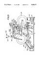
- controlis a throttle handle that is rotationally mounted on a handlebar of the frame of the motorcycle simulator.
- the computerreceives the control signal and causes the frame to move forwardly and upwardly to simulate the conduct of a so-called "wheelie" maneuver.
- a potentiometeris mounted in the handlebar of the frame and is operably engaged with the throttle handle, so that when the throttle handle is rotated, the potentiometer generates the control signal and sends the control signal to the computer.
- the control signalis representative of the position of the handle relative to the frame.
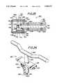
- the throttle handleincludes an annular hollow grip having a wall, a closed end, and an open end, and defining a longitudinal axis.
- an elongated shaftis disposed within the annular grip coaxially with the grip, and the shaft has a first end attached to the closed end of the grip and a second end extending into a portion of the simulator. This portion is preferably a handlebar having an open end, wherein the second end of the shaft extends into the open end of the handlebar.
- the potentiometeris operably connected to the second end of the shaft for generating the control signal in response to rotational movement of the grip.
- a support tubeis positioned in the grip between the wall of the grip and the shaft. The support tube has an end, and the end of the support tube is connected to the handlebar.
- at least one bearingis positioned between the wall of the grip and the support tube.
- a bracketis attached to the handlebar and a screw is threadably engaged with the bracket for holding the potentiometer onto the bracket.
- the bracketis preferably a two-piece bracket, to reduce potential binding of the potentiometer.
- the operable engagement of the computer with the frameis effected by a wheelie motor, which is electrically connected to the computer through an encoder, and by a cam, which is engaged with the wheelie motor.
- the wheelie motorcan be caused to rotate in the clockwise and counterclockwise directions by the encoder in response to commands from the computer.
- the camis connected to a wheelie member, and the wheelie member connected to the frame, for translating rotational motion of the wheelie motor into translational motion of the frame relative to the beam.
- the computercan command the encoder to cause the wheelie motor to vibrate the frame, to simulate passage of the frame over rough terrain. More particularly, the computer can be programmed such that when the simulated position of the frame in the space contained in the computer program correlates to the position of rough terrain in the space, the computer rapidly sends a series of alternating first and second command signals to the encoder.
- the first command signalcauses the encoder to pass a positive voltage to the motor to turn the motor in the clockwise direction
- the second command signalcauses the encoder to pass a negative voltage to the motor to turn the motor in the counterclockwise direction.
- the motor, and hence the camrapidly alternates its direction of rotation. Consequently, the wheelie member rapidly reciprocates relative to the beam, and this rapid reciprocating motion is transferred through the links to the frame.
- the computercan cause the encoder to activate the motor to move the frame in a wheelie-simulating motion. More specifically, the computer receives the control signal from the potentiometer, and in response to the control signal orders the encoder to rapidly rotate the motor through a predetermined angular range. This rapid rotation of the motor is transferred through the cam and wheelie member to the frame.
- the system of linksis configured such that when the wheelie member urges against the frame, the frame moves forwardly and then upwardly relative to the beam.
- the control signal from the potentiometeris conducted through an amplifier and a differentiator prior to being sent to the computer.
- the computerreceives both the control signal, which indicates how far the throttle handle was turned, and the time derivative of the control signal, which indicates how rapidly the throttle handle was turned. Based upon the control signal and its derivative, the computer determines what the magnitude of the resultant wheelie motion of the frame should be. Consequently, the computer can control the encoder to cause the wheelie motor-cam-wheelie member system to move the frame an amount appropriate for the computed magnitude of the wheelie.
- the simulator of the present inventionalso includes a means to cause the frame to move in a swinging motion to simulate the motion of a motorcycle during a turn.
- This swinging meansincludes a handlebar that is rotatably attached to the frame, and a slew generator operably coupled to the frame.
- a linkage systeminterconnects the handlebar and the slew generator.
- the framehas a longitudinal axis and a rear portion, and the rear portion of the frame is distanced from the handlebar.
- the slew generatorincludes an elongated rolling pin which is rotatably disposed adjacent the rear portion of the frame and is oriented with its longitudinal axis generally perpendicular to the axis of the frame. Further, the slew generator also includes a slew motor which coupled to the rolling pin for causing the rolling pin to rotate about the longitudinal axis of the rolling pin.
- a brackethas a forward end connected to the rear portion of the frame and a rear end distanced from the frame, and a pallet roller is connected to the rear end of the bracket.
- the pallet rolleris disposed on the rolling pin.
- the bracketis an A-shaped bracket.
- a bearing rolleris rotatably attached to the rear portion of the frame for supporting the frame.
- the weight of the frameis supported by the bearing roller, and not the pallet roller.
- a roller springis connected in tension to the rear portion of the frame and the rear end of the A-shaped bracket.
- the pallet rolleris wine barrel-shaped.
- the first and second ends of the pallet rollerhave diameters which are less than the diameter of the pallet roller near the middle of the pallet roller.
- a vehicle simulatorcomprises a frame on which a person can sit, and a handlebar rotatably attached to the frame.
- a slew generatoris operably coupled to the frame, and a linkage system interconnects the handlebar and the slew generator for causing the slew generator to move the frame in response to rotational movement of the handlebar.
- a "stand-up" version of the vehicle simulatorcomprises a base and a computer having a predetermined computer program simulating a space.
- a handlebaris rotatably mounted on the base, and a post is rigidly connected to the handlebar.
- a signal generatoris connected to the post for generating a control signal in response to rotation of the handlebar relative to the base, the signal generator being electrically connected to the computer.
- a video monitoris electrically connected to the computer for displaying a changing video image of the space in response to the control signal.
- a vibrational motoris electrically connected to the computer and is operably engaged with the base for causing the base to vibrate in response to the computer program. More specifically, the vibrational motor has a rotor shaft, and a weight is attached to the motor shaft for causing the shaft to vibrate when the shaft rotates, to thereby simulate passage of the simulated vehicle over rough terrain, or idling.
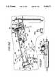
- FIG. 1is a right rear perspective view of the preferred embodiment of the present bicycle simulation system showing its intended use by a bicyclist.
- FIG. 2is a second right rear perspective view of the overall embodiment of FIG. 1.
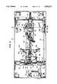
- FIG. 3is a top view of the embodiment of FIG. 2, showing a portion of the bicycle as it is supported from below by the mechanical support assembly.
- FIG. 4is a cross-sectional side view of the embodiment of FIG. 3 taken along lines 4--4.
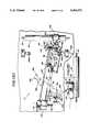
- FIG. 5is a cross-sectional side view of the left side interior of the base enclosure of FIG. 3 taken along lines 5--5.
- FIG. 6is a detail view of the connection of the main horizontal beam with a portion of the gimbal assembly.
- FIG. 7is a left front perspective view of the gimbal assembly and the forward portion of the main horizontal beam.
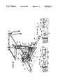
- FIG. 8is a right front perspective view of the bicycle frame and a portion of the mechanical support assembly as configured when the bicycle is in a wheelie position.
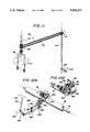
- FIG. 9is a side view of the wheelie assembly in its downward position.
- FIG. 10is a side view of the wheelie assembly in its upward position.
- FIG. 11is a right front perspective view of the steering assembly concealed within the bicycle frame.
- FIG. 12Ais a left front perspective view of the linkage assembly and the roller assembly.
- FIG. 12Bis a left rear perspective view of the roller assembly and the yoke assembly.
- FIG. 13Ais a top view of the mechanical assembly shown in its operating position when the bicycle is being directed forwardly.
- FIG. 13Bis a rear view of the roller assembly in its operating position shown in FIG. 13A.
- FIG. 13Cis a top view of the mechanical assembly shown in its operating position when the bicycle is being directed about a right-hand curve.
- FIG. 13Dis a rear view of the roller assembly in its operating position shown in FIG. 13C.
- FIG. 13Eis a top view of the mechanical assembly shown in its operating position when the bicycle is being directed about a left-hand curve.
- FIG. 13Fis a rear view of the roller assembly in its operating position shown in FIG. 13E.
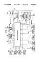
- FIG. 14is a block diagram of the computer and input/output (I/O) devices of the present bicycle simulator invention.
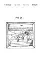
- FIG. 15is a diagram of the simulated bicycle track and bicycle drones corresponding to a representative screen provided by the computer and video display of FIG. 14;
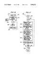
- FIG. 16is a flow diagram of the preferred bicycle model of the present invention.
- FIG. 17is a flow diagram of the "game" function used in the bicycle model of FIG. 16;
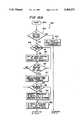
- FIGS. 18A,18Btogether form a flow diagram of the "add -- forces" function used in the "game” function of FIG. 17;
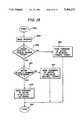
- FIG. 19is a flow diagram of the timer interrupt function of the bicycle model
- FIG. 20is a perspective view of the presently preferred motorcycle simulator embodiment of the present invention.
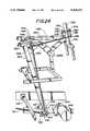
- FIG. 21is a left side, perspective view of the motorcycle simulator shown in FIG. 20, with the vacuum-formed body and the base removed;
- FIG. 22is a left side, perspective view of a portion of the steering linkage and wheelie linkage of the motorcycle simulator shown in FIG. 21, with portions broken away;
- FIG. 23is a right side, perspective view of the motorcycle simulator shown in FIG. 20, with the vacuum-formed body and the base removed;
- FIG. 24is a right side, perspective view of a portion of the steering linkage and wheelie linkage of the motorcycle simulator shown in FIG. 23, with portions broken away;
- FIG. 25is a cross-sectional view of the throttle handle of the motorcycle simulator, as seen along the line 25--25 in FIG. 20;
- FIG. 26is a perspective view of a stand-up embodiment of the motorcycle simulator of the present invention.
- FIG. 27is a block diagram of the signal processing components of the motorcycle simulator.
- FIG. 28is a flow diagram showing the portion of the computer program which causes the frame of the motorcycle simulator to move.
- the present inventionis a bicycle simulator 10 which permits a user (bicyclist) 12 to mount and maneuver a bicycle mechanism ("bicycle") 14, having an authentic appearing configuration, in several degrees of freedom to simulate actual bicycle riding and racing.
- the bicyclist 12may not only pedal the bicycle 14 in as aggressive a manner as desired, but may lean the bicycle 14 from side to side while simultaneously steering the handlebars in simulation of travel about a curve.
- the bicyclistcan pull a "wheelie,” i.e., pull the bicycle rearward in simulation of forward motion on the rear wheel only.
- a mechanical support assemblyis integrated within the bicycle simulator 10 to support the bicycle 14 in a fashion which permits movement in the above-described manner.
- the bicycle simulator 10also includes a means for displaying and broadcasting simulated movement of the bicycle 14 which enhances the pleasure derived from racing the bicycle 14.
- the bicycle simulator 10employs a computer (not shown), housed within an upright cabinet 16, which operates a computer program designed to model simulated movement of the bicycle 14 on a video display 18.
- the computergenerates an animated variable terrain racing track 20 on the video display 18 as well as displaying the progress of one or more animated bicycles drones moving thereon.
- the computercontrols output from a sound system (housed within the upright cabinet 16) to create audio sounds. Simulated progression of the bicycle 14 upon which the bicyclist 12 sits is depicted on the video display 18 by way of the computer animation that is discussed herein below.
- the handlebars 22 of the corresponding simulated bicycleare visible on the video display 18.
- the bicyclistEnhanced by visual display of the racing track and an accompanying audio soundtrack, the bicyclist experiences a sense of racing the bicycle along a variable terrain track--alone or in competition with other racers. The bicyclist's enjoyment is further enhanced by the force of wind blown across himself and the bicycle by a variably controlled blower (also housed within the upright cabinet 16) in response to pedaling speed of the bicycle 14 by the bicyclist 12.
- the mechanical support assembly(not shown) referred to above is housed within a base enclosure 24 which also supports the upright cabinet 16.
- the mechanical support assemblyprovides a means for more effectively simulating actual bicycle racing and includes the ability to augment pedalling action. Translation of the mechanical support assembly is monitored by the computer which receives position and speed signals from several sensors secured to the mechanical support assembly.
- the mechanical support assemblyincludes a "follower means” for allowing the bicycle to lean and move laterally in response to the bicyclist's steering of the bicycle 14.
- the mechanical support assemblyalso includes a "wheelie means” for simulating rearward rotation of the bicycle in a vertical plane about an axis orthogonal to, and proximate to the rear wheel of, the bicycle.
- the mechanical support assemblyis configured to alternatively add mechanical resistance or assistance to the bicyclist's pedaling action.
- the bicycle 14has a configuration designed to resemble a conventional bicycle; i.e., a bicycle frame 30, a seat 32 for a bicyclist to rest upon, rotatable pedals 34, steerable handlebars 36, first and second handbrakes 38a and 38b attached to each side of the handlebars 36, a front tire 40a and a rear tire 40b.
- the bicycle frame 30further comprises a cross tube 42 and a seat tube 44 both of which house a steering assembly described in more detail below.
- the bicycle frame 30includes a steering column 46 and a front fork 48.
- a meansis provided for bolting the tires in a stationary fashion so as to eliminate possible injury by the inadvertent placement of a bicyclist's fingers or hand near the tires 40a, 40b.
- the bolting meansare bolts 49a and 49b which extend through the bicycle frame 30 and into the rigid rims supporting the tires 40a and 40b respectively.
- the bicycle 14is supported from below by the mechanical support assembly (not shown in full) that is normally concealed from view within the base enclosure 24.
- a portion of the mechanical support assembly which extends upwardly toward the bicycleis protectively hidden by a chain guard 50 extending downwardly from the pedals 34.
- that portion of the mechanical support assembly extending through the top wall of the base enclosure 24is the seat tube 44 of the bicycle frame 30, as will be described in greater detail below.
- the balance of the mechanical support assemblyis enclosed within the base enclosure 24 comprising a housing 54 sufficiently sturdy to support the weight of the bicyclist (not shown) upon mounting and dismounting the bicycle 14.
- An openingshown in FIG.
- the base enclosure 24includes a rotatable turntable 56 which securably covers the opening in the housing 54 while safely concealing the mechanical support assembly which might otherwise present a hazard to the bicyclist 12. As will be explained further is association with FIG. 4, the turntable 56 rotates in a "lazy-Susan" fashion.
- the upright cabinet 16which houses the computer, the sound system and the variably controlled blower (each not shown). These components will be described in detail hereinafter.
- the computermodels simulated movement of the bicycle 14 as it progresses on the variable terrain track 18 using the selected software program, described in more detail below.
- a plurality of audio speakers 60a and 60b, integrated with the computer-controlled sound systemare mounted in the upright cabinet 16 to permit announcement of the progress of the animated bicycle on the track 18, as well as to transmit the normal ambient sounds associated with competitive bicycle racing. Enhancing racing simulation is the variably controlled blower for simulating wind conditions during the race.
- the variably controlled bloweris positioned behind an air grill 62 and directs forced air across the bicyclist in response to the bicyclist's pedalling action.
- the preferred embodiment of the present inventionalso includes an electronic token receptacle 64 for activation of the system by the bicyclist.
- the token receptacle 64is not necessary for the operational effectiveness of the present invention.
- a bicyclistactivates the bicycle simulator 10 by depositing a token or coin in the token receptacle 64 or by turning on a conventional power switch (in non-arcade use).
- the computeris then activated to operate the software program which generates the starting point of the racing track on the display screen 18.
- the bicyclistmay then mount the bicycle 14, placing his feet upon the pedals 34 and hands on the handlebars 36.
- the bicyclistthen awaits the start of the race.
- the computer programsignals the beginning of the race, the bicyclist is permitted to begin manipulating the bicycle to correspondingly move the animated bicycle along the track.
- the bicyclistrotates the pedals 34 in a forward direction, steers the handlebars 36 in a reciprocating fashion and selectively applies the hand brakes 38a, 38b so as to control movement of the animated bicycle as it progresses along the racing track.
- the bicyclistis permitted to steer the bicycle 14 so as to cause lateral movement of the bicycle 14 from side to side, and rearwardly in a "wheelie” fashion, if so desired.
- particular movements of the bicycle 14are monitored by a plurality of sensors which communicate with the computer, which responds thereto by generating signals causing the display 18 to illustrate the progressive movement of the animated bicycle on the variable terrain track.
- the computersignals the end of the race on the display screen 18, at which point the bicyclist stops pedalling and may dismount from the bicycle 14.
- the bicyclistwill have experienced a truly simulated feel of manipulating a bicycle while watching progression of its animated counterpart on the track in the display screen 18 and while listening to announcements of that progression from audio speakers 60.
- FIGS. 1 and 2operation of the bicycle 14 is virtually identical to operation of a conventional bicycle on a variable terrain roadway.
- FIG. 3a top view of the bicycle 14 is shown with the mechanical support assembly, housed in the base enclosure 24, revealed.
- the bicycle 14is partially shown for ease of describing its relative position to the mechanical support assembly. It should be appreciated that although the mechanical support assembly is usually not visible, the top face of the housing 54 has been deleted to reveal the mechanical assembly therewithin. In addition, the upright cabinet (shown in FIG. 2) has also been deleted to reveal the forward portion of the mechanical assembly.
- the bicycle 14includes the handlebars 36, the cross tube 42, the seat 32 and the rear tire 40.
- first and second handgrips 68a and 68b and the first and second handbrakes 38a and 38beach extending outwardly from first and second potentiometer housings 72a and 72b.
- Each of the handbrakes 38a, 38bare pivotally secured from the housings 72a, 72b such that their pivotal movement is monitored by a brake potentiometer (not shown) enclosed within the potentiometer housings 72a and 72b.
- the speed of the animated bicycle progressing on the display screensee FIGS.
- the brake potentiometersgenerate signals to the computer as an indication of whether the handbrakes 38a, 38b are being applied. As such, when the handbrakes 38a and 38b are applied, the brake potentiometers signal the braking action of the bicyclist to the computer which reflects in alteration of the speed of the animated bicycle on the racing track.
- the mechanical support assemblycan be seen positioned below the bicycle 14.
- the mechanical support assembly of the present inventionincludes a plurality of individual components linked together so as to support the bicycle 14 in an easily translatable fashion.
- the mechanical support assemblycomprises a main beam 82 extending between a gimbal assembly 84, at the front end of the bicycle simulator 10, and a yoke assembly 86 at the rear end thereof.
- the main beam 82is positioned horizontally.
- the gimbal assembly 84will be described in more detail in FIGS. 6 and 7 while the yoke assembly 86 will be discussed in more detail below in association with FIGS. 8-10.
- the yoke assembly 86supports the rear end of the main horizontal beam 82 by way of a roller assembly 88 which rotatably rests upon a rolling pin 90.
- the roller assembly 88is described in more detail in association with FIG. 12A and 12B.
- the rolling pin 90is rotatably supported about a rolling pin axle 92 and is mechanically linked to rotation of the pedals 34 and a drive axle 94 housed within the gimbal assembly 84. Extending forward of the drive axle is a motor 96 which alternatively generates mechanical resistance and power assistance to rotation of the pedals 34 by the bicyclist. While mechanical resistance to pedalling functions to simulate bicycle travel on uphill terrain, mechanical power assistance uniquely simulates travel on downhill terrain. During periods of downhill travel, the bicyclist may "coast,", i.e. continue forward movement without actually pedalling.
- the motor 96 of the present inventionis preferably of a type having reverse direction capabilities to permit variable direction torque to be applied to the motor 96, as described more fully below.
- the motor 96preferably is electrically connected to the computer so as to be controlled thereby wherein alternative resistive and power assistance may be exerted on rotation of the drive axle 94 by varying the speed of the motor shaft.
- the motor 96is responsive to the computer which, depending on the conditions of the track at any particular location, affects the ease or difficulty of bicyclist pedalling action. As will be discussed in greater detail in reference to FIGS. 13A-13F, effective lateral movement of the mechanical support assembly depends upon continuous rotation of the rolling pin 90.
- a motor velocity sensorPositioned on the rear side of the motor 96 is a motor velocity sensor, or optocoupler 97a which detects the rotational speed of a motor shaft 96i extending out the rear and front sides of the motor 96.
- the optocoupler 97ais mounted to the rear side of the motor 96 by a bracket 97b which supports the optocoupler immediately adjacent a hub light 97c axially secured to the rear end of the motor shaft 96i.
- the motor shaft 96irotates at a certain speed. This speed is monitored by the optocoupler 97a which is connected to the computer.
- Speed signals generated by the optocoupler 97aare received by the computer in order to vary the speed of the animated bicycle as it progresses along the variable terrain track.
- the faster the motor shaft 96i rotatesthe faster the animated bicycle progresses along the racing track.
- the slower the motor shaft 96i rotatesthe slower the animated bicycle progresses.
- resistance to pedalling action as applied by the motor 96will result in a slower rotation of the drive axle 94 absent accelerated pedalling effort by the bicyclist. Pedalling resistance will be applied during travel upon uphill inclined surfaces. Consequently, absent increased pedalling effort by the bicyclist, the speed of rotation of the drive axle 94 will be reduced, thereby reflecting in slower progression of the animated bicycle along the track.
- One preferred embodiment of the optocoupler 97ais manufactured by Honeywell and designated as model no. SPX-5129-1.
- the assembly of components which mechanically transfer rotational action of the pedals 34 to the rolling pin 90comprise a plurality of belts and pulleys, as can be seen in FIG. 3.
- a clutch belt 98transfers pedalling action to an idler coupling 100 journaled within the yoke assembly 86 and consisting of two rigidly secured idler pulleys 102 and 104 which rotate in unison.
- the clutch belt 98passes over the first idler pulley 104 and transfers energy to the second idler pulley 102. This energy is further transferred from the first idler pulley 102 to a drive belt 106 which connects the idler coupling 100 to a universal joint ("U-joint") pulley 108 secured to the drive axle 94. While the drive axle 94 will be described in greater detail in association with FIGS. 6 & 7, the belts 98, 106 and the idler coupling 100 will be described further in association with FIG. 8.
- the motor 96adds resistance and power assistance to bicyclist pedalling through the drive axle 94.
- a motor belt 110links the motor 96 with the drive axle 94 and circulates over a motor pulley 112 and a first drive axle pulley 114 secured to the drive axle 94.
- Adjacent to the first drive axle pulley 114is a second drive axle pulley 116 over which circulates a roller belt 118 which connects the drive axle 94 with the rolling pin 90.
- the mechanical connection between the drive axle 94 and the rolling pin 90will be described in more detail in association with FIG. 5.
- rotation of the pedals 34directs rotation of the drive axle 94 and the rolling pin 90.
- the direction of rotation of the rolling pin 90is opposite to the direction of rotation of the pedals 34 and the drive axle 94.
- the drive belt 106which extends between the yoke assembly axle 86 and the drive axle 94, and the roller belt 118, which extends between the drive axle 94 and the rolling pin 90, are both relatively long. As such, they are subject to a certain degree of sagging and stretching.
- the drive belt 106 and the roller belt 118normally rest slightly loose due to the following design dimensions.
- the center-to-center pulley separation lengthsare preferably slightly smaller than those recommended by manufacturers for the belts. This discrepancy is provided to accommodate inaccuracies in manufacturing tolerances that might otherwise cause the center to center dimensions to exceed the recommended separation length, thereby causing ineffective transfer of mechanical energy.
- the tension devicecomprises an idler pulley continuously exerted on the belt by the force of a spring.
- a first tension pulley 122is pivotally secured to the main horizontal beam 82 and downwardly applied to the drive belt 106 by the force of a spring 124.
- a second tension pulley 126is applied to the roller belt 118 by the force of a second spring 130.
- the drive axle 94positioned within the gimbal assembly 84, comprises a short shaft segment 132, extending through and supporting the U-joint pulley 108.
- the drive axle 94also comprises a longer shaft segment 134 connected to the first shaft 132 by a universal joint 136.
- the second shaft 134 of the drive axle 94extends through and rigidly supports the first and second drive axle pulleys 114 and 116, respectively, both positioned on the opposite side of the universal joint 136 from the U-joint pulley 108.
- the first drive axle pulley 114accepts circulation of the motor belt 110 which transfers mechanical energy from the motor 96 to the drive axle 94.
- the bicycle simulator 10is capable of adding pedalling resistance or pedalling assistance to rotation of the drive axle to simulate travel on variable terrain.
- the second drive axle pulley 116accepts circulation of the roller belt 118 which transfers mechanical energy from the drive axle 94 to the rolling pin 90.
- the beltsare of a gearbelt type, i.e., having teeth which securably engage corresponding teeth in gearbelt pulleys.
- Preferred embodiments of the gearbelts and gearbelt pulleys contemplated for the present inventionare manufactured by Browning Mfg. Division, Emerson Electric Co. of Maysville, Ky.
- a "follower system”which directs lateral movement of the bicycle 14 and simultaneous leaning thereof to simulate travel about a curve in response steering of the handlebars 36.
- the bicyclistrotates the handlebars 36 by grasping one or both of the hand grips 68 to direct pivotal movement of the roller assembly 88 through a steering assembly 140 and a linkage assembly 142.
- the steering assembly 140is enclosed within the frame of the bicycle 14; specifically, the cross tube 42 and the seat tube (not shown), to minimize exposure of the bicyclist to moving mechanical components.
- rotation of the roller assembly 88 in response to rotation of the handlebars 36causes the bicycle 14 to move laterally within the base enclosure 24 relative to the rolling pin 90.
- This relative movement of the bicycle 14 with respect to the rolling pin 90simulates travel about a curve and will be further appreciated by the detailed description in reference to FIGS. 13A through 13F.
- the steering assembly 140will be described in greater detail in association with FIG. 11, while the linkage assembly 142 will be described in more detail in association with FIG. 12.
- FIG. 4a side view of the mechanical support assembly below the bicycle 14 is shown.
- the upright cabinet 16Positioned atop the forward end of the base enclosure 24 is the upright cabinet 16 which houses, among other things, the blower 140.
- the blower 140directs forced air across the bicycle 14 through the grill 62 at speeds which are variably controlled by the computer in response to pedalling action to simulate changing wind conditions.
- the computerthe video display and the audio speakers which are each positioned in the upper portion of the upright cabinet 16.
- the base enclosure 24which comprises the housing 54 having a top wall and the rotatable turntable 56.
- an opening 137 in the top wall of the housing 54permits the extension of the seat tube 44 through the top wall of the base enclosure housing 54 in order to effectively support the bicycle 14.
- the rotatable turntable 56securably covers the opening in the housing 54 and encircles a collar 139 directly secured to the seat tube 44 which engages an inner annular edge of the turntable 56 as the bicycle 14 is directed laterally.
- the opening 137 in the top wall of the base enclosure housing 54has an elongate kidney shape wherein lateral movement of the bicycle 14 is generated about an arc.
- the present inventionincludes a loosely fitted cover 58 which encircles the seat tube 44 and rests directly on the turntable 56.
- the collar 139forces the turntable 56 to rotate accordingly while the cover 58 protects a bicyclist from the moving mechanical parts below.
- the gimbal assembly 84At the forward end of the mechanical support assembly is the gimbal assembly 84 and the motor 96. At the rear end of the mechanical support assembly is the linkage assembly 142, the yoke assembly 86, the roller assembly 88 and the rolling pin 90.
- the bicycle simulator 10includes an additional feature for simulating actual bicycle racing action; namely, a means for pulling a "wheelie.” While the wheelie means will be described in detail in association with FIGS. 8-10, it is identified briefly here.
- the wheelie meanscomprises a pivoting member 144 extending forward from the yoke assembly 86 and pivotally secured thereto about a yoke assembly axle 146. The pivoting member 144 is secured at its forward end to a lower portion of the seat tube 44 of the bicycle 14. The wheelie assembly will be described in more detail in association with FIGS. 8-10.
- a wheelie sensor or potentiometer 148monitors the position of the pivoting member 144 and is mounted to the side of the main horizontal beam 82 by a bracket 149. As actuated by movement of two pivoting sensing arms 150a and 150b, the wheelie potentiometer 148 detects whether or not the bicycle is in a wheelie position and generates an electrical signal accordingly.
- the first sensing arm 150ais pivotally secured to the potentiometer 148 while the second sensing arm 150b is pivotally secured to the pivoting member 144. As such, rotation of the pivoting member 144 causes rotation of the second sensing arm 150b and the first sensing arm 150a wherein rotation of the latter is detected by the potentiometer 148.
- the computerreceives this signal and varies the progression of the animated bicycle along the racing track as displayed on the display screen.
- the corresponding animated bicycle of the bicycle 14is displayed only as a set of handlebars (see FIGS. 1 and 2), the progression along the track is displayed as it would be viewed by the bicyclist.
- movement of the bicycle while the bicyclist“pulls a wheelie” reflects in continued forward movement about the rear bicycle tire only.
- the bicyclemay react differently when in a wheelie mode. For instance, depending upon the speed that the bicycle is travelling, pulling a wheelie while moving up an incline may reflect on the animated bicycle leaving the track surface in the form of a jump. Accordingly, the bicyclist is able to control movement of the animated bicycle in a more realistic fashion.
- the base enclosure 24is provided with a plurality of canisters 150, two of which are positioned at the forward corners and two of which are positioned at the rear corners.
- the bicycle simulator 10is selectively mobile and may be directed easily from one location to another about a generally flat surface.
- Each canister 150is provided with a conventional wheel lock (not shown) which permits the canisters to be locked in place so as to avoid any undesired movement of the base enclosure 24 during use.
- the roller belt 118is wound about the second drive axle pulley 116 and further wound about a rolling pin pulley 152, an idler pulley 154 and the tension pulley 126.
- the purpose of the idler pulley 154is to reverse the direction of rotation of the rolling pin (shown in FIG. 3) relative to rotation of the drive axle 94.
- the roller belt 118is subject to sagging and must therefore be pulled taught in order to maintain an effective transfer of mechanical energy.
- This pulling actionis accomplished by continuously urging the tension pulley 126 away from the rolling pin pulley 152 by a linear spring.
- the tension spring 130is secured at one end to the base enclosure 24 and at its other end to the tensioner plate 128 which supports the tension pulley 126.
- the gimbal assembly 84may be described in greater detail. As indicated above, the gimbal assembly 84 is positioned oblique to a vertical plane such that the main horizontal beam 82, normally positioned in the horizontal plane, is secured to a gimbal assembly 84 at an angle less than 90°.
- the horizontal beam 82is secured to a beam housing 156 by two gusset plates 158 preferably welded to each side of the beam 82.
- the beam housing 156is pivotally secured within the gimbal assembly 84 (shown more clearly in FIG. 7).
- the beam housing 156is pivotally secured to the gimbal assembly 84 about an axis 158 at an angle "x" to the vertical plane.
- the connection of the beam housing 156 to the gimbal assembly 84will be explained in greater detail in association with FIG. 7.
- the angle xis equal to 25° .
- lateral movement of the main horizontal beam 82necessarily entails some vertical translation of the main horizontal beam 82 as it moves laterally from side to side. This vertical movement of the main horizontal beam 82 forces the gimbal assembly to rotate forwardly in the direction of the arrow 162.
- FIG. 1To relieve stress on the gimbal assembly 84, it can be seen by referring to FIG.
- axle 160which spans the side walls of the base enclosure (shown in FIG. 3).
- the axle 160is radially secured within a set of pillow bearings (not shown) which are commonly known and available to those skilled in the art.
- the balance of the gimbal assembly 84may be more fully described.
- the main horizontal beam 82 of the mechanical support assemblyis secured to the beam housing 156 which pivots about an axis oblique to a vertical plane. It is this oblique orientation which causes the main horizontal beam 82 to lean as it rotates laterally within the base enclosure of the bicycle simulator. (See FIGS. 13D and 13F). It is to be understood that the main horizontal beam 82 is pivotally secured at its forward end to the beam housing 156 while it is free to move laterally at its rear end within the base enclosure. With this arrangement, the bicycle is permitted to lean as the handlebars are turned by the bicyclist to direct the bicycle about a curve.
- the gimbal assembly 84comprises a housing having a top weldment 164 and a lower weldment 166.
- the weldments 164 and 166are spaced apart and rigidly supported by four side panels 168a through 168d.
- Journaled between tapered bearings (not shown) which are secured within the upper and lower weldments 164, 166are two short housing axles 170 secured to the upper and lower sides of the beam housing 156.
- the lower axleis not fully in view in FIG. 7. With this arrangement, the beam housing 156 is permitted rotational movement within the gimbal assembly 84 to accommodate lateral movement of the main horizontal beam 82.
- a U-joint pulley housing 172Secured to the far side of the beam housing 156 as viewed in FIG. 7 is a U-joint pulley housing 172 which partially encloses the U-joint pulley 108 about which the drive belt 106 travels. As indicated above, the U-joint pulley 108 is secured to the drive axle 94 so that pedalling action by the bicyclist is transferred through the drive belt 106 to the drive axle 94 and ultimately to the rolling pin (not shown) through the roller belt 118. To accommodate pivotal movement of the main horizontal beam 82, the U-joint 136 is inserted between the short shaft segment 132 (hidden from view by the beam housing 156) and the longer shaft segment 134 which together comprise the drive axle 94.
- the short shaft segment 132 on the far side of the U-joint 136is permitted lateral movement synchronous with the main beam 82.
- the beam housing 156, the U-joint pulley 108, the U-joint pulley housing 172 and the drive belt 106move in unison.
- first and second drive axle pulleys 114 and 116are radially secured about the long shaft segment 134 of the drive axle 94.
- the first drive axle pulley 114is linked to the motor (not shown) via the motor belt 110 while the second drive axle pulley 116 is linked to the rolling pin (not shown) by the roller belt 118.
- a significant feature of the present inventionis the ability to more accurately simulate bicycle travel about a variable terrain track.
- the motorcan be variably controlled to not only add mechanical resistance to pedalling action, to simulate uphill travel, but also to add mechanical assistance to pedalling action to simulate downhill coasting. Rotational resistance and assistance to pedalling action is translated to the drive axle 94 by the motor belt 110.
- the motor 96is operated at variable speeds in the same radial direction as the drive axle 94.
- the computersignals the motor to apply a reverse torque to the drive axle 94 so as to resist the bicyclist's pedalling.
- resistanceis added to pedalling action because it becomes harder to rotate the drive axle 94.
- Varying degrees of resistancecan be added by the variably controlled motor by simply varying the amount by which the motor's rotational speed is decreased in correspondence to the amount of the uphill grade.
- the computersignals the motor to increase the rotational speed of the drive axle 94 as caused by the bicyclist's pedalling action, thereby augmenting the bicyclist's efforts.
- Thistranslates into easier pedalling by the bicyclist as the drive axle 94 is being rotated at a faster rate by the motor.
- the bicyclistcan coast along the downhill portion without pedalling as the bicycle continues to advance along the track.
- variable degrees of powermay be augmented based on the speed of the motor as controlled by the computer and corresponding to the amount of the downhill grade.
- pedalling assistance and resistancecan be effectuated by the employment of gearbelts and gearbelt pulleys, as indicated above, which function similarly to gears and eliminate possible belt slippage. In addition, they maximize mechanical transfer efficiency.
- FIG. 8There it is shown that the pedals 28, secured to the bicycle frame 30, are connected to a pedal sprocket 180 in a manner typical of conventional bicycles.
- the pedal sprocket 180is linked to a lower sprocket 182 by a continuous chain 184.
- the lower sprocket 182is axially connected to a sprocket pulley 186 by a support axle 187 which itself is secured to the pivoting member 144.
- the clutch belt 98is wound about the sprocket pulley 186 and extends about the first idler pulley 104 in the yoke assembly 86.
- the first pulley 104is secured about a yoke assembly axle 146 which rotatably extends through apertures in arms 191 and 193 of the yoke assembly 86.
- the outer idler pulley 102is secured adjacent to the pulley 104 and about the yoke assembly axle 146, as explained above.
- the drive belt 106is wrapped about the pulley 102. In this manner, rotational energy is transferred from the pedals 28 via the pedal sprocket 180 and continuous chain 184 to the lower sprocket 182.
- the energyis then transferred from the lower sprocket 182 to the sprocket pulley 186 and then via the clutch belt 98 to the pulley 104. From pulley 104 the energy is transferred via the pulley 102 to the drive belt 106, from whence it is transferred to the drive axle 84 as described above.
- the wheelie assemblymay be more fully described.
- the wheelie meanscomprises the pivoting member 144, referred to above in association with FIG. 4.
- the pivoting member 144is journaled at its rearward end about the yoke assembly axle 146. At its forward end, the pivoting member 144 is rigidly secured to the bottom of the seat tube 44 which supports the bicycle frame 30. With this arrangement, the pivoting member 144 is pivotable in a somewhat restrained fashion by the thrust of the bicyclist.
- the bicycle frame 30is positioned relative to the pivoting member 144 such that shifting of the bicyclist's weight a sufficient distance in the rearward direction causes the pivoting member 144 to pivot upwardly and rearwardly thereby simulating a wheelie.
- wheelie movement of the bicycle 14can be seen in FIG. 4 by the rearward position of the bicycle shown in phantom.
- pivotal motion of the pivoting member 144necessarily causes the movement of the lower sprocket 182 and the sprocket pulley 186 relative to the yoke assembly axle 146. While slight slippage of the clutch belt 98 occurs, it is negligible and has not effect on the effective transfer of mechanical energy from the pedals 28 to the drive axle (not shown). This arrangement was designed to advantageously permit such energy transfer while still providing a means for simulating a wheelie.
- FIGS. 9 and 10the limiting device can be described.
- the wheelie assemblycan be seen positioned in a horizontal fashion.
- the pivoting member 144normally rests on a resilient cushion 200 secured to the top side of the main horizontal beam 82.
- At the forward end of the pivoting member 144is bottom portion of the seat tube 44 which supports the bicycle frame (shown in FIG. 8).
- Attached to the lower portion of the seat tube 44is a first stop plate 202 that is engageable with a second stop plate 204 positioned atop a pedestal 206 rigidly secured to the top surface of the main horizontal beam 82.
- the pivoting member 144When the bicyclist throws his weight rearwardly, at the same time pulling upwardly on the handlebars, the pivoting member 144 will be caused to pivot upwardly as shown in FIG. 10. There it can be seen the two stop plates, 202, 204 are engaged when the bicycle has reached its rearward limit. As such, the pivoting member 144 is limited to rotation between the cushion 200 and the second stop plate 204. Depending on the extent of rotation desired in simulating a wheelie, the height of the pedestal 206 can be varied accordingly, thereby increasing or decreasing the range that the pivoting member 144 can rotate.
- the steering assembly 140the linkage assembly 142 and the roller assembly 88 can be described in detail.
- the follower systemfunctions to effectively simulate bicycle travel about a curve
- the steering assembly 140can be more fully appreciated.
- the bicycle steering column 46extends below the handlebars (not shown) and supports the front tire fork 48.
- Radially secured to the steering column 44is a first steering sprocket 210 such that rotation of the handlebars causes rotation of the steering column 44, the first steering sprocket 210 and the front tire fork 256 in the direction of arrows 212.
- a second steering sprocket 214is radially supported about a steering shaft 216 housed within the seat tube (shown in FIG. 4) of the bicycle frame (not shown).
- the first steering sprocket 210is linked to the second steering sprocket 214 by a chain 218 housed within the cross tube (shown in FIG. 4) of the bicycle frame.
- the steering shaft 216is secured at its base to a reciprocating arm 222 which is rotated in the direction of the arrow 224 in correspondence with the steering column 46.
- the reciprocating arm 222is an integral member of the linkage assembly 142 described below in reference to FIG. 12A.
- the reciprocating arm 222as with the handlebars and the steering sprockets 210, 214, rotates in the direction of arrows 212 and 224 in a generally horizontal plane.
- the steering shaft 216is connected to the linkage assembly 142 by the reciprocating arm 222.
- the linkage assembly 142comprises the reciprocating arm 222 connected to a first connecting rod 226.
- the first connecting rod 226is connected to a first end of the reciprocating arm 222 such that rotation of the first connecting rod 226 results in linear movement of the first connecting rod 226 as shown by the arrow 228.
- a rocker arm 230is rotatably secured about the yoke assembly axle 190 (FIG. 8) and is connected on a first end to the first connecting rod 226 and on a second end to a second connecting rod 232.
- Linear movement of the first connecting rod 226causes rotation of the rocker arm 230 in the direction of arrow 234 and also linear movement of the second connecting rod 232 in the opposite direction.
- the second connecting rod 232is, in turn, pivotally secured to a roller guide 240 which is rigidly secured to the roller assembly 88.
- the second connecting rod 232is thus linked to the roller assembly 88 in a fashion so that linear movement of the second connecting rod 232 causes rotation of the roller assembly 88 in a horizontal plane as indicated by the arrows 242.
- the roller assembly 88will subsequently be described in more detail in association with FIG. 12B.
- a steering potentiometer(not shown) which monitors movement of the rocker arm 230 and thereby provides an indication of the position of the linkage assembly 142 in response to the steering assembly 140 (FIG. 11).
- the steering potentiometersends an electrical signal indicative of the position of the handlebars of the bicycle as the bicyclist steers the bicycle. This signal is received by the computer which directs movement of the animated bicycle on the display screen along the racing track. By steering the bicycle to the left, the animated bicycle is caused to veer to the left accordingly. Similarly, when the bicycle is turned to the right, the computer directs the animated bicycle to the right on the display screen.
- a roller stop 244is connected to the bottom portion of the roller assembly 88 and extends forwardly thereof.
- the roller stop 244functions to redirect the rotational position of the roller assembly 88 relative to the rolling pin 90 when the main horizontal beam (not shown) has reached the desired limit to its lateral movement within the base enclosure (not shown). Aiding the return of the roller stop 244 to its normally straight position in alignment with the main horizontal beam is a return spring 245 secured at its other end to the floor of the base enclosure. Actual operation of the roller assembly stop 244 will be discussed further below in association with FIGS. 13A through 13F.
- the roller assembly 88illustrated as viewed from the left rear. While a roller assembly may be designed in various configurations which permit horizontal rotation thereof, the preferred embodiment comprises a roller 246 supported by a roller support 248.
- the roller 246is permitted to freely spin about a roller axle 250 due to its frictional engagement with the rolling pin 90 which spins about the rolling pin axle 92.
- the roller support 248is a U-shaped bracket rigidly secured to a roller shaft 252 rotatingly supported within tapered bearings (not shown) and extending between the rearward end of the horizontal beam 82 and the back portion of the yoke assembly 86.
- the top of the roller shaft 252is journaled within bearing housings 254a and 254b.
- the lower bearing housing 254bis secured directly to the rear end of the main horizontal beam 82 while the upper bearing housing 254a is secured directly to a plate 258 extending rearwardly from the top rear portion of the yoke assembly 86.
- Secured across the top of the roller support 248is the roller guide 248 referred to above in association with FIG. 12A. Since the roller guide 240 is secured to the linkage assembly 142 (FIG. 12A), movement of the linkage assembly results in the rotation of the roller assembly 88 in a horizontal plane. It should now be appreciated that rotation of the steering column 46 (shown in FIG. 11), in turn, causes the reciprocating arm 222 (shown in FIG.
- FIGS. 13A through 13Fthe follower system may be described in detail.
- FIGS. 13A and 13Billustrate the mechanical support assembly as it is positioned when the bicycle is brought by the bicyclist into a straight direction (i.e., in the middle of the base enclosure).
- FIGS. 13C and 13Dillustrate the mechanical support assembly as positioned when the bicycle is turned to the right to simulate travel about a curve. In this position, the mechanical support assembly is located to the bicyclist's left side of the base enclosure.
- FIGS. 13E and 13Fillustrate the mechanical support assembly when the bicycle is turned to the left (i.e., positioned to the bicyclist's right side of the base enclosure).
- the mechanical support assemblyis shown positioned perpendicular to the rolling pin 90 in alignment with its mid-section. With this arrangement, the bicyclist experiences simulated travel in a straight direction.
- the mechanical support assemblycomprises the main horizontal beam 82 secured at its forward end to the gimbal assembly 84 and at its rear end to the yoke assembly 86 and the roller assembly 88.
- Extending outwardly from the side of the pivoting member 144is the lower sprocket 182 and the sprocket pulley 186 which are physically secured together and are journaled about the axle 187.
- the yoke assembly 86comprises a u-shaped frame having arms 191 and 193 in which the yoke assembly axle 146 is secured.
- the yoke axle 146supports the first and second idler pulleys 102, 104 as well as the pivoting member 144 (FIG. 8).
- roller assembly 88is supported from the rear portion of the yoke assembly 86. As indicated above in association with FIGS. 11-12B, rotation of the handlebars 36 causes the reciprocation of the roller assembly 88 through the steering assembly (not shown) and the linkage assembly 142.
- bicyclist pedalling action in the forward directionrotates the drive axle 94 in the direction of the arrow 260 which ultimately results in the reverse direction of the rolling pin 90. Because the roller 246 of the roller assembly 88 frictionally engages the rolling pin 90, clockwise rotation of the rolling pin 90 causes counter-clockwise rotation of the roller 246. In order for the follower assembly to operate effectively, the bicyclist must be pedalling so that rotation of the rolling pin 90 relative to the roller 246 facilitates lateral movement of the roller assembly 88 from one side to the next as will be discussed in FIGS. 13C through 13F.
- FIG. 13Aone of several potentiometers used to sense the position of the bicycle is shown.
- a pivot sensor or potentiometer 270secured to the forward portion of the main horizontal beam 82 is a pivot sensor or potentiometer 270 supported from a rigid bracket 272 extending from a rear portion of the gimbal assembly 84.
- the pivot potentiometer 270movement of the main horizontal beam 82 through sensing arms 274 and 276 which are pivotally secured to each other and to the main horizontal beam 82.
- FIGS. 13C and 13Dmovement of the main horizontal beam 82 from one side to the next triggers rotation of the sensing arm 276 thereby changing the resistance of the pivot potentiometer 270.
- the pivot potentiometer 270monitors direction of the bicycle in cooperation with the steering potentiometer. As with all of the potentiometers, the pivot potentiometer 270 is electrically interfaced with the computer so that relative movement of the bicycle may be translated into movement of the corresponding animated bicycle on the display screen.
- the present inventionincludes a wheelie potentiometer 148 (FIG. 4).
- the wheelie potentiometer 148is mounted to the side of the pivoting member 144 and generates an electrical signal in response to the position of the pivoting member 144. In this manner, the computer receives additional information regarding the position of the animated bicycle relative to the variable terrain track.
- the main support for the bicycle extending upwardly from the main horizontal beam 82is the seat tube 44. It can also be seen that when the main horizontal beam 82 is positioned in the middle of the rolling pin 90, that the seat tube 44 is aligned in a vertical plane. As will be explained below, lateral movement of the main horizontal beam from one side to the other of the base enclosure causes the seat tube 44 to lean oblique to the vertical plane from one side to the other. This leaning capability permits more accurate simulation of travel about a curve.
- FIGS. 13C and 13Dthe mechanical support assembly is shown positioned to the left side of the rolling pin 90.
- the handlebars 36are turned towards the right in simulation of travel about a righthand curve.
- this clockwise rotation of the handlebars 36results in the counter-clockwise rotation of the roller guide 240 thereby rotating the roller assembly 88 accordingly.
- the roller assembly stop 244is rigidly secured to the roller assembly 88 as described above, rotation of the roller assembly 88 causes radial movement of the stop 244 in the direction of the bicyclist's left side.
- a limit rod 284extends axially from the left side of the yoke assembly axle 146 as a means for limiting laterally movement of the mechanical support assembly to the left.
- several mechanical componentsare positioned on the left interior side of the base enclosure. (See FIG. 5). These components are susceptible to damage if the mechanical support assembly is permitted to move to the left excessively.
- the length of the limit rod 284is designed such that the end of the rod 284 almost meets the interior wall of the base enclosure (not shown) when the roller stop 244 engages the limit wheel 282a.
- the present bicycle simulator 10is a device that allows the user, or bicyclist 12 to simulate movement through an artificial, computer-created track universe.
- the track universe of the preferred embodimenta portion of which is displayed on the video display 18 at any one time (for example, as further shown in FIG. 15), is designed by one or more artists who preferably use a computer animation tool such as, for example, the Super 3D program that is licensed by Silicon Beach Software of San Diego, Calif.
- track 20e.g., endless loop or linear
- track polygonis concisely defined and stored in the memory as a set of Cartesian points (the polygon vertices) which all lie in the same plane.
- the track polygonsare strictly limited to having either three or four vertices.
- the polygonal tilesrepresent the track surface 10 on which the bicyclist moves.
- the track surface 10has hills and valleys, banked corners, and other like features which would be typical of an authentic track for BMX racers.
- the track 10can also comprise other settings, including "fantasy" tracks which do not relate to typical venues for bicycling.
- the track surface 10is surrounded by other graphical objects built from polygons (such as a grandstand) which are separated from the track 20 and from one another by empty space.
- the track 10is suspended inside of a colored box so as to provide the illusion of a ground surface underneath the undulating track 10.
- Polygons adjacent to the track 10, e.g., side skirtscan simulate the features of a terrain having surface irregularities.
- the video display 18is updated so as to maintain a view into the universe from the first-person perspective of the bicyclist 12.
- forces of the bicyclist 12 and natureare applied to a bicycle simulation or model so as to move the simulated bicycle through the track universe.
- Further references hereinbelow to the bicycle 14may also be used to indicate the simulated bicycle but it will be understood from the surrounding text that the simulated bicycle of the bicycle model is not the physical bicycle 14.
- the bicyclist 12applies a force on the pedals 34 (FIG. 2) of the bicycle 14 so as to increase the pedal velocity, as is commonly measured in revolutions per minute (rpm), and proportionately increase the force to the tires (of the bicycle model) in contact with the track 20.
- This rotational pedaling forceis commonly called thrust.
- the thrustis sensed and the video display 18 is updated to provide the bicyclist 12 with the appearance of moving forward around the track 20.
- the bicyclist 12can also apply an opposing force (or resistance) to forward movement by using the front and rear hand brakes 38a, 38b on the bicycle 14.
- the bicyclist 12can turn the bicycle 12 in the plane of the track surface by moving the handlebars 36 (FIG. 2).
- An out-of-plane forceis affected when the bicyclist 12 pulls up on the handlebars 36, causing the bicycle 14 to "pop a wheelie" as previously described.
- the motion of the bicycle 14 in the track universeis represented and maintained in the bicycle model by a vector containing three dimensional position, velocity and acceleration information.
- the bicycle modeluses the reference frame of the bicyclist 12.
- the massis normalized to one (or ignored) to simplify calculations.
- the forces applied to a bicycleare well-known and may be consulted in any number of publications.
- the motion of the bicycle 14 in the track universeis communicated to the bicyclist 12 by the video display 18.
- the bicycle modelis preferably embodied in computer software which is executed by the computer so as to generate three-dimensional polygon graphics to the video display 18.
- the bicyclist 12receives visual feedback that simulates travel through the track universe.
- the computercontrols the motor 96 (FIG. 3) by a motor velocity control line (not shown). By transmitting predetermined commands, the computer can vary the velocity of the motor 96.
- the motor 96has a given dynamic range of velocity. Theoretically, the motor 96 would provide a maximum resistance so as to prevent any forward movement at all by the bicyclist 12, for example, when climbing a very steep incline.
- a precise emulation of the actual worldis clearly undesirable and so such an event will not occur.
- the preferred bicycle modeltherefore distorts reality so that the forces of nature acting against the thrust of the bicyclist 12 are not overly burdensome. For example, when the bicycle model simulates the bicyclist 12 climbing a hill, at the base of the hill the actual natural forces which would confront a bicyclist are generated by the motor 96. With time, the actual forces are gradually mitigated by the bicycle model, without presenting unrealistic feedback to the bicyclist 12.
- a minimal resistance provided by the motor 96corresponds to the small frictional forces associated with level surface.
- the motor 96is directed to disengage from the rolling pin 90 (FIG. 3)
- this situationcorresponds, for example, to the bicycle 14 (of the bicycle model) being airborne after a jump.
- the motor 96is directed to increase its velocity, the bicyclist 12 is given power assistance via the action of the pulley mechanism, previously described, on the rolling pin 90.
- the bicycle modelsimulates downhill motion, for example.
- the video display 18is updated every display cycle. For the most part, the period of the display cycle depends on the number of visible polygons which are presented to the video display 18 by the computer, as the display of each additional polygon is the result of an incremental computational burden. In the presently preferred embodiment, the video display 18 is updated with a frequency in the range of 10 to 16 Hz.
- a computer 400controls a number of input/output (I/O) devices connected to the bicycle simulator 10 (FIG. 1).
- the computer 400is preferably housed in the upright cabinet 16 of FIG. 1.
- Central to the operation of the computer 400is a main board, or motherboard 402 which comprises the central control functions of the computer 400.
- motherboard 402Central to the operation of the computer 400 is a main board, or motherboard 402 which comprises the central control functions of the computer 400.
- motherboard 402Central to the operation of the computer 400 is a main board, or motherboard 402 which comprises the central control functions of the computer 400.
- the separation of the computer into the motherboard 402 and associated circuits and boards as presented in FIG. 14is, of course, just one possible logical and physical arrangement of the computer 400.
- the motherboard 402includes a microprocessor (not shown) such as a Motorola 68010 or another microprocessor from the 680 ⁇ 0 family.
- the motherboard 402also includes a graphics processor (not shown) such as, for example, one of the Texas Instruments 340 Graphic System Processor (GSP) family.
- the preferred motherboard 402further includes eight analog-to-digital (A/D) convertors for sensor input ports, a set of switch input ports, an optocoupler input port, a video controller circuit and a timer interrupt circuit, none of which are shown.
- A/Danalog-to-digital
- a start switch or button 404, an abort switch or button 406, a coin 1 switch 408 and a coin 2 switch 410are connected through a set of switch inputs (not shown) to the motherboard 402.
- the coin switches 406, 408are housed in the token receptacle 64 (FIG. 2).
- the start and abort switches 404, 406are mounted on the housings 72a, 72b (FIG. 3) located on the handlebars 36.
- the coin switches 408, 410indicate whether coins have been received and thus whether to allow the bicyclist 12 to play the arcade game embodiment of the bicycle simulator 10.
- the start switch, or button 404can be depressed by the bicyclist 12 to start the bicycle simulator 10.
- the bicycle simulator 10can be started by pedaling, depression of the handbrakes 70a, 70b or pushing the abort button 406.
- the abort button 406can be depressed by the bicyclist 12 to terminate the operation of the bicycle simulator 10, for example, if the bicyclist 12 becomes too winded to continue. By aborting operation, the motor 96 is disengaged so that the bicyclist 12 can safely leave the simulator 10.
- a set of sensors 412, 414, 148, 418 and 270are also connected to the motherboard 402. These sensors are preferably embodied as potentiometers.
- the front and rear brake sensors 412, 414indicate to the computer 400 whether either of the handbrakes 38a,b (FIG. 3) have been depressed.
- the brake sensors 412, 414are located in the housings 72 mounted on the handlebars 36 as shown in FIG. 3.
- the wheelie sensor 148indicates to the computer 400 when the front wheel of the bicycle 14 has left the ground (in the sense of the bicycle model).
- the wheelie sensor 148is located inside the horizontal beam 82 (FIG. 3), forward of the pivot point at 192.
- the steering sensor 418senses the axial position of the handlebars 36 (FIG.
- FIG. 13AThe location of the pivot sensor 270 on the bicycle 14 is shown in FIG. 13A.
- the microprocessor on the motherboard 402is served by on-board random access memory (RAM) of 32 k bytes and a program ROM of 1 Megabyte where the bicycle model software is stored.
- RAMrandom access memory
- ROMprogram ROM
- an auxiliary memory 422is connected to the motherboard 402 which in the preferred embodiment comprises 64 k bytes of RAM and 1.28 Megabytes of ROM.
- the motherboard 401employs an audio processor 426 to generate music, shouts, noises and other such sounds from the speakers 60.
- a digital signal processor 424including a DSP chip such as an Analog Devices ADSP-2100, is connected to the motherboard 402 for scaling, translation and rotation of the polygons which will be displayed to the user 12 on the video display 18.
- the motherboard 402also sends velocity commands to a motor/fan controller 430.
- the presently preferred controller 430utilizes pulse width modulation (PWM) of the AC line (not shown) to vary the speed of the blower, or fan 146. For example, as the bicyclist 12 pedals faster, the computer 400 commands the controller 430 to proportionally increase the fan velocity hence simulating the naturally expected increasing rush of air associated with a speeding bicycle.
- the motor/fan controller 430also controls the dual-direction motor 96 which is connected to the rolling pin 90 (FIG. 3) of the bicycle simulator 10.
- the controller 430also uses PWM but of alternate halves of the AC line to control the velocity and direction of the motor 96. To drive the motor 96 in one direction, the positive halves of the AC line are used.
- the dual-direction motor 96is a motor of standard DC brush/commutator construction that is optimized for the load of the bicycle 14.
- the portion of the motor/fan controller 430 that controls the motor 96is similar (if modified) to Dayton SCR Controller No. 6X165 available from W. W. Grainger of Chicago, Ill. However, the W. W. Grainger controller would have to be modified for the simulator 10 so that the controller would accept computer input.
- the thrust of the bicyclist 12is indirectly calculated by the bicycle model as a function of the motor velocity.
- the velocity of the motor 96is measured by the motor velocity sensor 109.
- the motor velocity sensor 109is embodied by an optocoupler as set forth above.
- the sensor 109is mechanically connected to the motor 96.
- the sensor 109thus provides an electrical signal to the motherboard 402 which is proportional to the speed of the motor 96.
- FIG. 15is an exemplary screen display that is presented on the video display 18 of the arcade game embodiment of the bicycle simulator 10.
- the screen display of FIG. 15shows one perspective at one point and time in a track (or graphical) universe 448.
- the perspective of the track universe 448is from the first-person viewpoint of the bicyclist 12.
- a number of drone bicyclists 450a, 450b, 450c, 450d, 450eare presented to appear on the track 20 in front of the bicyclist 12.
- the drones 450are modeled so that they follow the contours of the track 20, but they may go airborne after cresting a hill as shown, for example, by the drone 450e.
- the track 20, on which the bicyclist 12 attempts to maneuver through the graphical universe 448,is shown to be in the forward direction of bicycle travel.
- the preferred track 20includes a number of connected track polygons such as the one indicated at 454.
- handlebars 22(as shown in FIG. 1), representing those of the bicycle 14, can be displayed in the foreground of the screen display.
- the bicycle simulator 10 of the present inventionincludes a computer program called the bicycle model which is illustrated in diagrammatic flow format and generally designated at 470 in FIG. 16.
- the bicycle model 470is written in the "C" language and cross-compiled on a Digital Equipment Company VAX computer using a Green Hills Software, Inc. "C” compiler available from Oasys, a division of Xel, Inc. of Waltham, Mass.
- the bicycle model 470is then executed on the Motorola 68010 microprocessor located on the motherboard 402 (FIG. 14).
- the motherboard 402FIG. 14
- the bicycle model 470begins at a power-on state 472 after the power switch (not shown) has been switched to an "on" position.
- the bicycle modelnext moves to a state (“calibrate") 474, wherein the model 470 calibrates the motor 96 (FIG. 3) as will be further discussed below.
- the calibration state 474is necessary for at least two reasons. First, if the motor 96 is not operational, then this fact will be detected during calibration. Second, as the motor 96 ages, the rotational force generated by the motor 96 will tend to decrease. Therefore, the control of the motor 96 will be dependent upon the limits of the most recently measured rotational force.
- calibrate 474compares the velocity called for by the bicycle model 470 against the velocity read from the motor velocity sensor (optocoupler) 109 (FIG. 14).
- Spin delay datais gathered, as will be described, and then compared with a default table of spin delays, i.e., the difference in time between when the velocity command was sent and the time when the motor 96 has reached the specified velocity.
- the gathered spin delay datais then compared against a predetermined table of default values stored in a 2 k byte zero-power RAM on the motherboard 402. Then, using standard statistical techniques, if the gathered spin delay data is less than 5% different, for example, than the predetermined data, the new data is stored in zero-power RAM for use as the new default data.
- the motor 96is assumed to be out of tolerance due to operator error such as, for instance, the bicycle 14 being jiggled, and the default data is used by the bicycle model 470.
- the data gathering step of calibrate 474includes the steps of measuring the time to change velocity from the motor 96 at zero velocity to maximum velocity (spin-up), e.g., about a 1/4 second, and measuring the time to change velocity from the motor 96 being at maximum speed to zero velocity (spin-down). Similar steps are performed for 3/4 speed and 1/2 speed spin-up and spin-down times.
- a loopis entered at the loop state 478.
- the soft reset 476is caused whenever the bicyclist 12 puts coins in the bicycle simulator 10 as detected by the computer 400 via the coin switches 408, 410.
- the bicycle model 470enters the game function 480 which will display animation comprising a continuous sequence of views around the track 20 as, for example, shown in FIG. 15.
- the bicycle model 470moves to a state 482 to handle the "wave".
- the bicyclist 12may select one of four separate tracks 20 and associated with each region are five waves, or cycles, through the region.
- the bicycle model 470will complete operation on the current wave, and will then move from the handle wave state 482 to the loop state 478 to continue until the given number of waves are complete or more money is deposited by the bicyclist 12.
- the loop 478-482will continue in the so-called "attract mode", wherein a prerecorded game is replayed, until either more money is deposited or the bicycle simulator 10 is powered off.
- the bicycle model 470also includes interrupt-driven software which is invoked asynchronously in relation to the control flow shown in FIG. 16. More specifically, a timer interrupt function will be discussed below with reference to FIG. 19.
- FIG. 17the flow of control for the game function 480 (introduced in FIG. 16) is shown in FIG. 17.
- the game function 480is entered by the bicycle model 470 at a start state 484, from whence the bicycle model 470 moves to a loop state 486.
- the loop state 486is the beginning of the previously noted display cycle.
- the display cyclecorresponds to a single update of the video display 438 (FIG. 14).
- the bicycle model 470calculates a motor control value (roller assist or "rl -- assist") which will later be sent to the motor 96 by the timer interrupt (further discussed below with reference to FIG. 19).
- the doforceroller state 488calculates a motor control value based on a percentage of the full range of resistance.
- the range of resistancevaries according to the rl -- assist value, from -255 for maximum pedal resistance to +255 for essentially freewheeling. If the bicycle 12 is determined to be airborne (as later described), then rl -- assist is set to +255 to freewheel.
- the scaled range valuewill thus be a positive number and the minimum resistance number will be a negative number.
- the scaling factor and minimum resistancedepend on option settings that are determined by the operator of the bicycle simulator 10 and on bicyclist feedback such as whether the handlebars 36 (FIG. 3) are turned.
- rl -- assist-128, or half-scale resistance.
- the bicycle model 470sets rl -- scale to zero, resulting in rl -- min being written to the motor controller 430 to simulate pedaling up a steep hill.
- the control value rl -- assist to be sent to the motor controller 430is set to -255, regardless of the difficulty setting reflected by the preselected value rl -- min.
- the bicycle model 470moves to a state ("get -- thrust") 490 wherein the motor velocity sensor 109 is read and the pedal thrust generated by the bicyclist 12 is calculated.
- the bicycle model 470needs to have a value for thrust if the motion of the bicycle 14 in the track universe 448 is to have any meaning at all.
- the calibration state 474 of FIG. 16provides the spin-up and spin-down times of the motor 96 without any thrust being applied. Therefore, during the gameplay mode of the game function 480, if, after the calibrated delay time, the motor velocity read from the motor velocity sensor 109 is greater than that commanded by the controller 430 (FIG. 14), then the difference is attributed to thrust.
- the amount of thrust the cyclist 12 generatesdepends on the change in velocity of the motor 96 as well as the current velocity of the motor 96. For example, if the rolling pin 90 (FIG. 3) is stopped, very little pedaling is required to generate a large change in motor velocity. On the other hand, if the rolling pin 90 is spinning at maximum velocity, even a small change in velocity indicates a large thrust. Therefore, the get -- thrust state 490 makes use of a precalculated table of thrust multipliers ("thrust -- mult") that depend on the current motor velocity.
- the thrust -- mult tablewas derived by looking at the data generated by the calibrate state 474.
- the bicycle model 470next reads the track database associated with the track 20 to look-up the polygon (e.g., polygon 454 of FIG. 15) that is nearest to the last calculated position of the bicycle 14.
- the orientation of the bicycle 14is then adjusted according to the angle that the polygon makes with the horizontal. For example, the bicycle 14 may be riding up a ramp as represented by a track polygon that is inclined with respect to the horizon.
- the bicycle model 470adjusts the bicycle motion according to the surface normal of the selected polygon (assuming the bicycle 14 is not airborne).
- the bicycle modelthen moves to a state 494 wherein the position (Cartesian coordinates) of the bicycle 14 in the track universe 448 is determined from the velocity of the bicycle 14 and the intervening time between display cycles. This position is then reflected in the viewpoint of the bicyclist 12 into the track universe 448 as presented on the video display 18 (FIG. 1). From the state 494, the bicycle model 470 moves to a decision state 496 wherein a test is made to determine whether the game cycle, or wave, is over. If the wave is not over, then the bicycle model 12 moves from the decision state 496 to the loop state 486 to continue the display cycle. Otherwise, the bicycle model 470 moves to a stop state 498 and terminates the game function 480.
- a decision state 496wherein a test is made to determine whether the game cycle, or wave, is over. If the wave is not over, then the bicycle model 12 moves from the decision state 496 to the loop state 486 to continue the display cycle. Otherwise, the bicycle model 470 moves to a stop state 498 and
- the control flow for the add -- forces function 492 of the bicycle model 470is shown in FIGS. 18a, 18b.
- the add -- forces function 492is entered at a start state 500.
- the bicycle model 470moves from the start state 500 to a state 506 wherein the position of the bicycle 14 is tested to determine whether the bicyclist 12 is on the ground. If the bicycle 14 is on the ground (e.g., touching a track polygon), then the bicycle model 470 transitions to a decision state 508 and, using information read from the brake sensors 412, 414 (FIG. 14), determines whether the handbrakes 38 (FIG. 3) have been applied by the bicyclist 12.
- the bicycle model 470moves to state 510 to set the three-dimensional components of acceleration of the bicycle 14 to zero. This is a simplifying assumption which follows from the physical phenomenon that the acceleration of the bicycle will tend toward zero after brakes are applied.
- the bicyclist's three-dimensional velocityis reduced according to the amount of brake force sensed by the brake sensors 412, 414.
- the bicycle model 470then moves to a decision block 512 wherein the query is made as to whether the bicycle 14 is off of the track surface 20 (FIG. 15), i.e., off-road. Each polygon of the track 20 in the track universe 448 will indicate whether it is a section of track and so this test is a simple check of polygon information.
- the decision state 512may also be reached when the bicycle model 470 determines that the brakes have not been applied at the state 508. If, at state 512, the bicyclist 12 is off of the track 20, the modeling software applies additional braking force to compensate for rough terrain as indicated at state 514.
- the decision state 516is next entered from the state 514 by the bicycle model 470 to determine whether the bicycle 14 is turning.
- This statemay also be entered from state 512. If the result of the test at state 516 is affirmative, that is, the bicycle 14 is turning as indicated by the steering sensor 418 (this value being read by the timer interrupt function as is shown in FIG. 19), then the momentum of the bicycle 14 is redirected with slippage to compensate for the lateral traction of the bicycle 14 after the bicycle model 470 moves to a state 518.
- the bicycle model 470moves to state 520.
- the model 470distorts reality by setting the bicycle velocity to a minimum value (e.g., if the bicyclist 12 is inside a pipe the velocity is increased by controlling the motor 96 (FIG. 3) via a preselected setting for the minimum velocity.
- the state 520may also be entered by a transition from state 516 after it is determined that the bicycle 14 is not turning.
- the model 470then moves from state 520 to a decision state 522 (FIG. 18B) to determine whether the bicyclist has just performed a wheelie. This information is available to the computer 400 from the wheelie sensor 148, as already described.
- the decision state 522may also be entered from the control path beginning at state 506 when it is determined that the player is airborne, and from there, the bicycle model 470 moves to a state 524 to set thrust equal to zero and pedal resistance to zero at state 524.
- the bicycle model 470moves to a state 524 to set thrust equal to zero and pedal resistance to zero at state 524.
- the boost in momentum due to the motor 96occurs for only one display cycle. However, the wheelie is simulated on the video display 18 for about 5 seconds before the natural force of gravity causes the wheelie to stop.
- the state 528is either entered by the bicycle model 470 from state 526 or the decision state 522 if the computer decides that the wheelie was not just popped.
- the force of gravityis transformed into the bicyclist's frame of reference and added to the three-dimensional acceleration vector.
- the bicyclist's thrustwhich was previously calculated at the state 504, is added to the acceleration vector at a state 530.
- the model 470next enters state 532 to apply the force of air resistance to both the acceleration and velocity vectors.
- the computerqueries whether the bicyclist 12 is off of the track surface 20. If the bicyclist 12 is on the track the model moves to a state 536. At state 536, if there is any pedal velocity (rpm), as calculated from the get -- thrust state 490 via the motor velocity sensor 109, then the bicyclist 12 is given some fixed minimum velocity such as in the range of 3 to 5 miles per hour, for example.
- state 537is entered to limit the bicyclist's top speed due to rough terrain. For instance, in the presently preferred embodiment the top speed is limited to 18 mph to 22 mph.
- the bicycle model 470places the bicyclist 12 back onto the polygon section of track surface 20 where he/she started.
- State 538is then entered by the model 470 from either state 536 or 537. In state 538, the model 470 calculates pedal resistance and power assistance from the forward velocity and the collision state of the bicycle 14.
- the collision stateis set whenever the bicyclist 12 brings the bicycle 14 (of the simulation) in contact with a wall, hay bale, tree or the like.
- the collision stateis determined as a function of what the bicycle 14 is in contact with and how it is moving.
- the add -- forces function 492terminates at a stop state 539.
- FIG. 19is a flow diagram showing the timer interrupt function which, as previously stated, is a portion of the bicycle model 470.
- the preferred motherboard 402includes a timer interrupt circuit comprising an oscillator set at, for example, 48 MHz, and a cascade of counters. In the present arcade game embodiment, the timer is set to generate an interrupt every 4 milliseconds. Thus, the timer interrupt function, shown in FIG. 19, will be executed once every 4 milliseconds by the bicycle model 470.
- the timer interrupt functionis entered by the bicycle model 470 at a start state 542 and, thereafter, moves to a state 544 to read the front brake 412, rear brake 414, wheelie 148, steering 418 and pivot 270 sensors (FIG. 14).
- the bicycle model 470then moves to a decision state 546 to test whether the motor 96 is required to develop reverse torque. This determination of motor torque direction, made at state 546, is based on the rl -- assist resistance value that was previously calculated in the doforceroller function 488. Reverse torque corresponds to a range of pedal resistance and would be required, for instance, when the bicyclist 12 begins cycling up an inclined plane on the simulated track 20 of the track universe.
- a commandis sent to the motor 96, via the motor/fan controller 430, to develop forward torque.
- the motor 96spins the rolling pin 90 (FIG. 3) to simulate travel in the track universe. If the forward torque is greater than that applied by the pedaling of the bicyclist 12, then the motor 96 provides power assistance to the bicycle 14. After the command specifying the amount of forward torque is sent to the motor 96, the timer interrupt function terminates at a stop state 550.
- the bicycle model 470determines that the motor 96 is required to develop reverse torque, i.e., maximum resistance, then the bicycle model 470 transitions to another decision state 552.
- the value read from the motor velocity sensor 109, at the get -- thrust function 490is checked to see if the motor 96 is actually spinning in a reverse direction.
- the time that the motor 96 spins in reverseis so small, for instance, between 4 milliseconds and 12 milliseconds, that the inertia of the rolling pin 90 (FIG. 3) is not overcome so that the rolling pin 90 does not spin in a reverse direction.
- the bicycle model 470determines that the motor 96 is not spinning in reverse, then the model 470 moves to a state 554 wherein a command is sent to the motor 96, via the motor/fan controller 430, to reverse the direction of the motor 96.
- a commandis sent to the motor 96, via the motor/fan controller 430, to reverse the direction of the motor 96.
- the bicyclist 12is overcoming the reverse torque of the motor 96 using leg muscles to increase thrust. It is thus desired to continue to cause the motor 96 to develop reverse torque so that the bicyclist 12 continues to feel pedal resistance.
- the timer interrupt functionterminates at the stop state 550.
- the bicycle model 470transitions to a state 556 to send a command to the motor 96 to halt spinning, i.e., develop no torque. In this way, the bicycle model 470 prevents possible injury to the bicyclist 12 caused by reverse spinning pedals, and also possible damage to the mechanical components of the bicycle simulator 10 which are designed to only move in a forward direction. The bicycle model 470 then transitions from state 556 to the stop state 550 to terminate the timer interrupt function shown in FIG. 19.
- the bicycle simulator 10provides numerous features which more realistically simulate bicycle riding as compared with prior art devices.
- the useris permitted to manipulate a bicycle mechanism having a conventional bicycle appearance within the realm of a track universe.
- the usercan realistically negotiate curves in the track by leaning the bicycle into the turn and moving it laterally across the system so that accentuated angular movement of the rear wheel and bicycle frame relative to the front wheel and handlebars is provided.
- the simulation systemprovides wheelie capabilities which more realistically provides vertical rotation about an axis proximate to the rear wheel.
- the present inventionprovides a means for simulating travel under variable terrain conditions, including the ability to experience downhill coasting. These features are enabled by coupling the mechanical subsystem to a computer, motor and a video display such that movement on the track universe is simulated. With such a system, a bicyclist can experience the thrill of bicycle riding solo, or in competition with other animated bicyclists, and obtain a vigorous workout with favourable excitement and enthusiasm.
- the simulator 600is a motorcycle simulator.
- the simulator 600includes a simulated motorcycle assembly 601 having a vacuum-formed shell 602 which simulates the body of a motorcycle.
- the simulator 600has two non-rotatable wheels 604, 606.
- the shell 502is supported on a tube 608, a portion of which is shown in FIG. 20.
- the tube 608extends upwardly from a base 610, and the base 610 includes a turntable 612 through which the tube 608 extends.
- the base 610 and turntable 612are, in essential respects, identical to the turntable 56 described above.
- FIG. 20also shows that the simulator 600 includes a cabinet 614.
- a computer(not shown in FIG. 20) is housed within the cabinet 614 for presenting a changing video display of a simulated space on a video monitor 616.
- the video monitor 616presents a first-person view of the simulated space to the rider (not shown) of the simulator 600.
- the computercauses the video monitor 616 to present a view of a simulated space as the space would be seen from the vantage point of a rider riding a motorcycle through the simulated space.
- the simulator 600includes a rotatable handlebar 618 that can be grasped and manipulated by a rider of the simulator 600.
- the shell 502 on which the rider sitsis caused to move in response to movement of the handlebar 618, to simulate the movement that an actual motorcycle has when being turned.
- a signalis sent to the computer causing the computer to change the image on the monitor 616 as appropriate to visually model the effects of turning through the simulated space.
- FIG. 20shows a throttle handle 620, which is rotatably attached to the handlebar 618.
- the rider of the simulator 600can grasp the handle 620 and turn the handle to simulate revving a motorcycle.
- a signalis sent to the computer in response thereto to cause the computer to move the motorcycle assembly 601 in a motion that emulates the motion an actual motorcycle has when undergoing a wheelie maneuver.
- the computerchanges the display on the video monitor 616 to visually model the effect of performing a wheelie on a motorcycle in the simulated space.
- a currency receiver 622may also be included for activating the simulator 600 in response to the insertion of a predetermined amount of currency in the receiver 622.
- the details of the motorcycle assembly 601can best be appreciated by referring to FIGS. 21-25. Specifically, the details of the wheelie mechanism can be seen in reference to FIGS. 21 and 22, the details of the steering mechanism can be seen in reference to FIGS. 22-24, and the details of the handle 620 can be seen best in FIG. 25.
- FIG. 21shows that the motorcycle assembly 601 includes a unitary frame 624 that is movably connected to a unitary beam 626.
- the frame 624is made of two inch by two inch (2" ⁇ 2") steel tubing.
- the shell 502 shown in FIG. 20is attached to the frame 624 by well-known means, e.g., bolting, so that when a rider sits upon the shell 502, the rider is being supported in part by the frame 624.
- the beam 626is shaped generally as a "T", having a horizontal bar 626a and a generally vertical bar 626b.
- the generally vertical bar 626bis slightly offset from a vertical wall 611 of the base 610 by an angle ⁇ of about 60 degrees.
- the frame 624is connected to the beam 626 via a coupler 628.
- the frame 624is connected to four links 628a, 628b, 628c, 628d and each link 628a-d is also connected to the horizontal bar 626a of the beam 626.
- each link 628a-dis rotatably connected to the frame 624 by means well-known in the arts such as by forming a first hole near a first end of each link 628a-d and a second hole in a portion of the frame 624, and then positioning a pivot pin (e.g., a pivot pin 630, shown connecting the link 628a to the frame 624) through the juxtaposed holes.
- a pivot pine.g., a pivot pin 630, shown connecting the link 628a to the frame 624
- each link 628a-dis rotatably connected to the beam 626 by means well-known in the art, such as by forming a first hole near a second end of each link 628a-d and a second hole in a portion of the beam 626, and then positioning a pivot pin (e.g., a pivot pin 632, shown connecting the link 628a to the beam 626) through the juxtaposed holes.
- a pivot pine.g., a pivot pin 632, shown connecting the link 628a to the beam 626
- each link 628a-dis made of steel, and has a length "1" of about eight inches (8"). Also, the distance “d" between the centers of the first and second holes of each link 628a-d is about five inches (5"). Further, the two front links 628c,d are oriented at an angle ⁇ of about forty-five (45) degrees, relative to the vertical wall 611 of the base 610.
- the frame 624includes a generally rectangularly-shaped strut 634 formed beneath the coupler 628.
- the strut 634 and other components of the frame 624can be welded or forged together to form a unitary frame 624, as shown.
- the vertical bar 626b of the beam 626is rigidly connected, as by welding, to a bearing bar 636.
- the bearing bar 636is pivotably connected to a bearing bar housing 638 which forms a portion of the base 610. More particularly, an end 642 of the bearing bar 636 is connected to a swing flange 641, and a swing pin 640 extends through the swing flange 641 and also extends through a portion of the bearing bar housing 638.
- the bearing bar 636can thus pivot about the swing pin 640.
- FIG. 22best shows that a motor flange 644 is bolted or welded to the bearing bar 636, and a wheelie motor 646 is bolted to the motor flange 644.
- the wheelie motor 646is a 1 horsepower electric motor
- an optical motor encoder 647is electrically connected to the motor 646.
- the optical encoder 647is a type optical rotary encoder made by Clarostat.
- the wheelie motor 646can turn a shaft 648, and the shaft 648 is in turn rigidly connected to a cam 650.
- Two preferably rubber-coated stops 652a, 652bare attached to the cam 650 and extend inwardly therefrom. The stops 652a,b can contact the bearing bar 636 during rotation of the cam 650 and thereby limit rotation of the cam 650, as shown in phantom.
- a cam pin 654is rigidly attached to the cam 650 and extends outwardly therefrom.
- a link pin 656is rotatably connected to the cam pin 654, so that as the cam 650 rotates, the rotational motion of the cam 650 is transformed into reciprocal motion of the link pin 656.
- the coupling 658 that couples the link pin 656 and the cam pin 654is a rod-end type coupling, such as the rod-end couplings made by Aurora Boaring Co. of Aurora, Ill.
- rod-end type couplingsare essentially ball-and-socket couplings that permit universal rotational motion between the links that are connected through the rod end coupling.
- a wheelie link 660is rotationally connected to the link pin 656 through a rod-end coupling 562. Together, the wheelie link 660 and the link pin 656 establish a wheelie member. With this arrangement, horizontal reciprocal motion of the link pin 656 is transformed into vertical reciprocal motion of the wheelie link 660.
- the wheelie link 660is in turn connected through a ball-and-socket joint 664 to the strut 634.
- the wheelie motor 646can turn the cam 650, and this rotational motion is transferred through the system of links and couplings described above to reciprocal motion of the wheelie link 660.
- the wheelie link 660can thus be made to push upwardly and pull downwardly on the frame 624, based upon the direction of rotation of the cam 650.
- the effect of the links 628a-dis to cause the frame 624 to initially move forwardly, relative to the beam 626 (and, hence, base 610), and then to cause the front end of the frame 624 (FIG. 21) to pivot upwardly to the position indicated by the dashed lines above the strut 634 in FIG. 22, in simulation of the motion of a motorcycle undergoing a wheelie maneuver.
- the wheelie motor 646can then be energized to turn the cam 650 such that the wheelie link 660 pulls the frame 624 back to the position shown in FIG. 21.
- two anti-wheelie springs 666a,bare connected in tension to the frame 624 and beam 626.
- the motorcycle simulator 600 of the present inventionalso includes a means to cause the frame 624 to move in a swinging motion, to simulate the motion of a motorcycle during a turn.
- this swinging meansincludes the handlebar 618 (FIG. 23) which, as discussed above, is rotatably attached to the frame 624.
- a slew generatorgenerally designated 668 in FIG. 23, is operably coupled to the frame 624.
- linkage systeminterconnects the handlebar 618 and the slew generator 668.
- linkage systeminterconnects the handlebar 618 and the slew generator 668.
- the handlebar 618is rotated by the operator of the simulator 600 to simulate turning a motorcycle, the motion of the handlebar 618 is transferred through the linkage system to the slew generator 668.
- the slew generator 668causes the rear portion of the frame 624 to swing relative to the front portion of the frame 624.
- FIG. 23shows that the frame 624 has a longitudinal axis 672. In relation to the axis 672, the frame 624 has a rear portion 674, and the rear portion 674 of the frame 624 is distanced from the handlebar 618.
- the handlebar 618includes a stalk 676, and the stalk 676 turns when the handlebar 618 is turned.
- a stalk bracket 678is rigidly attached to the stalk 676, and an end 680 of the stalk bracket 678 undergoes a side-to-side translational movement when the handlebar 618 (and, hence, the stalk 676) are rotated.
- a stalk link 682is rigidly connected to the end 680 of the stalk bracket 678, so that as the end 680 of the stalk bracket 678 moves translationally, the stalk link 682 also moves translationally.
- the stalk link 682is connected through a rod end coupling 684 to a first steering link 686.
- the first steering link 686is connected through a rod end coupling 688 to an upper steering bracket 689, and the bracket 689 is rigidly connected to a second steering link 590. Accordingly, it will be appreciated in reference to FIG. 24 that when the first steering link 686 is moved translationally, the bracket 689 is caused to rotate, which in turn rotates the second steering link 690.
- a first end 692 of the second steering link 690includes a ball 694, and the ball 694 is rotatably received in the socket 696 of an upper steering block 698.
- the upper steering block 698is rigidly connected to the frame 624.
- a second end 700 of the second steering link 690is ball-shaped and is rotatably received in the socket 702 of a lower steering block 704.
- the lower steering block 704is rigidly connected to the bearing bar 636 of the base 610.
- the second steering link 690is rigidly connected to a lower steering bracket 706, and an end 708 of the lower steering bracket 706 is caused to move translationally when the second steering link is rotated.
- a third steering link 710is connected to the lower steering bracket 706 through a rod end coupling 712.
- this translational motionis imparted to the third steering link 710 to cause the third steering link 710 to move forwardly or rearwardly, as appropriate.
- the third steering link 710is connected to a pallet roller bracket 714 through a rod end coupling 716. Specifically, the third steering link 710 is connected to an L-shaped portion 715 of the pallet roller bracket 714. When the third steering link 710 moves translationally, it causes the pallet roller bracket 714 to rotate about an axis 718.
- the bracket 714has two mounts 714a,b (mount 714a shown in FIG. 22, mount 714b shown in FIG. 23) extending downwardly from the bracket 714, and an axle 720 is connected to the mounts 714a,b between the mounts 714a,b.
- a pallet roller 722(FIGS. 22 and 23) is rotationally engaged with the axle 720.
- the pallet roller 722is made of polyurethane and is wine barrel-shaped, i.e., the first and second ends of the pallet roller 722 have diameters which are less than the diameter of the pallet roller 722 near the middle of the pallet roller 722.
- the pallet roller 722has first and second ends and a radial cross-section that is circular in shape, and the diameter of the cross-section taken at a location intermediate the ends of the roller 722 is greater than the diameter of the cress section of the roller taken near either end of the roller 722.
- the pallet roller bracket 714has an upwardly projecting shaft 724, and the shaft 724 is rotationally engaged with a pallet roller bearing 726.
- the pallet roller bearing 726is rigidly attached to or formed integrally with an A-shaped bracket 728, and the A-shaped bracket 728 is rigidly attached to the frame 624.
- a spring bracket 730is rigidly connected to the pallet roller bracket 714, and a return spring 732 is connected to the spring bracket 730 and a cross-bar portion 734 of the base 610 to urge the pallet roller bracket 714 into the at rest position (i.e., the position the pallet roller bracket 714 has when the handlebar 618 is oriented for straight travel of the simulated motorcycle) shown in FIG. 22.
- the pallet roller 722rests on an elongated cylindrical rolling pin 736.
- the rolling pin 736is caused to rotate by a slew motor 738 (FIG. 23). More specifically, the slew motor 738 turns a belt 740 (FIG. 21), and the belt 740 is engaged with the rolling pin 736 by means well-known in the art to rotate the rolling pin 736.
- the slew motor 738is a 1 horsepower electric motor, and the speed of the slew motor 738 is controlled by the computer of the present invention as more fully disclosed below, based upon the position of the throttle handle 620.
- FIGS. 22 and 23show that a bearing roller 742 is rotatably connected to the bearing bar 636 of the base 610. As shown, the bearing roller 742 can roll in a trough 744 that is rigidly attached to the base 610, and stops 746a, 746b limit the range of rolling motion of the bearing roller 742. It will accordingly be appreciated that substantially all of the weight of the frame 624 is borne by the bearing roller 742, and not the pallet roller 722.
- a pre-load spring 748is connected to an axle 750 of the bearing roller 742 and to the A-shaped bracket 728.
- the pre-load spring 748is in tension, with a tensional force of about one hundred pounds (100 lbs.).
- A-shaped bracket 728is rigidly connected to the bearing bar 636, and that the bearing bar 636 is pivotally connected to the base 10. Also recall that the bearing bar 636 is rigidly connected to the beam 626, so that as the bearing bar 636 moves, the entire beam 626 and frame 624 move. Consequently, turning the handlebar 618 causes the rear portion of the frame 624 to slew transversely relative to the longitudinal axis 672 of the simulator 600.
- the present inventionalso provides means for generating an electrical signal representative of turning motion of the handlebar 618, and turning motion of the wheelie motor 646.
- the stalk link 682is connected to one end of a potentiometer link 750, and the potentiometer link 750 is connected to a potentiometer bracket 752 through a rod end coupling 754.
- the potentiometer bracket 752is in turn pivotally connected to a fixed bracket 756, and the fixed bracket 756 is rigidly attached to the frame 624.
- a steering potentiometer 758is attached to the fixed bracket 756 and operably engaged with a shaft (not shown) of the potentiometer bracket 752.
- the output signal of the steering potentiometer 758changes when the handlebar 618 is turned, because the potentiometer bracket 752 (and shaft) is caused to move by the potentiometer link 750 when the handlebar 618 is turned.
- the signal from the potentiometer 758is sent to the computer of the present invention for processing as discussed below.
- a wheelie potentiometer 760is engaged with the cam 650 by means well-known in the art. Consequently, when the wheelie motor 646 turns the cam 650, the output signal of the wheelie potentiometer 760 changes. This signal is sent to the computer of the present invention, for processing as disclosed below.
- the potentiometers 758, 760are 5 k ohm potentiometers.
- the throttle handle 620includes an outer annular grip 762 and an inner cylindrical shaft 764 rigidly attached to or formed integrally with an end 768 of the grip 762.
- the end 770 of the shaft 764 which is opposite the end 768 of the grip 762is selectively engaged with a post 772 of a handle potentiometer 774, which is preferably a 5 k ohm potentiometer.
- a handle potentiometer 774which is preferably a 5 k ohm potentiometer.
- an engagement screw 776is threadably engaged with a channel 778 formed in the shaft 764, and the engagement screw 776 can be rotated to abut a flat surface 780 of the post 772 to hold the post 772 stationary relative to the shaft 764.
- the post 772 of the handle potentiometer 774is turned, causing the output control signal of the potentiometer 774 to change.
- the output control signal of the potentiometer 774is sent to the computer of the present invention for further processing, as described below.
- the potentiometer 774is fastened to the handlebar 618 via a two-piece bracket 782. More specifically, the potentiometer 774 is rigidly attached to an arm 784 of the bracket 782, and the arm 784 is in turn engaged with a groove 786 that is formed in a leg 788 of the bracket 782. The leg 788 is in turn bolted to a face plate 790 of the handlebar 618.
- the use of a two-piece bracket 782 as describedreduces the likelihood of the potentiometer 774 mechanically binding when the grip 762 is turned.
- FIG. 25shows that to support the grip 762 and shaft 764, an annular support tube 792 extends coaxially between the grip 762 and shaft 764.
- the support tube 792includes a flange 794, and the flange 794 is attached to a support plate 796 of the handlebar 618 by two elongated bolts 798a, 798b.
- Two cylindrical bearings 800,802are positioned between the grip 762 and support tube 792, and two additional cylindrical bearings 804, 806 are positioned between the support tube 792 and shaft 764.
- these bearings 800-806are type cylindrical bearings made by Boston Gear.
- the bearings 800-806radially support the components of the handle 620.
- a torsion spring 808is connected to the face plate 790 and a retainer screw 810.
- the retainer screw 810is threadably engaged with the shaft 764.
- two stops 812, 814are attached to the face plate 790, and the screw 810 can abut the stops 812, 814 to limit rotational motion of the grip 762.
- the grip 762can be easily removed from the handlebar 618 by unscrewing the bolts 798a, 798b.
- the potentiometer 774can easily be removed from the shaft 764 by unscrewing the screw 776 until the screw 776 no longer abuts the flat surface 780 of the post 772 of the potentiometer 774, and removing the potentiometer.
- the potentiometer 774can accordingly be easily replaced by another like potentiometer (not shown) by engaging the other potentiometer with the shaft 764 and tightening the screw 776 against the post of the other potentiometer.
- FIG. 26shows an alternate embodiment of the motorcycle simulator of the present invention, wherein the user stands in front of a handlebar assembly, generally designated 816.
- the assembly 816is connected to a support plate 818, and the plate 818 is rigidly connected to a game console or base (not shown).
- the assembly 816includes a handlebar 820, and the handlebar 820 has a stalk 822 which is rotatably engaged with the support plate 818 by means well-known in the art.
- a bar 824which preferably has a resilient outer coating extends outwardly from the stalk 822.
- a V-shaped bracket 826is rigidly attached to the support plate 818, as by welding, and the bar 824 is received in the V-shaped bracket 826.
- the stalk 822is also turned.
- the cooperation of structure between the bar 824 and the V-shaped bracket 826causes the bar 824 to ride up on one of the legs of the V-shaped bracket 826, causing the handlebar 820 to rise upwardly as a consequence, to give the user of the assembly 816 a tactile indication of turning.
- FIG. 26also shows that the stalk 822 is rigidly connected to the post 828 of a handle potentiometer 830.
- the handle potentiometer 830is a 5 k ohm potentiometer.
- a vibrational motor 719such as the motor disclosed in co-pending U.S. patent application Ser. No. 07/674,076, now U.S. Pat. No. 5,203,573, assigned to the same assignee as the present invention and incorporated herein by reference, is electrically connected to the computer and is operably engaged with the plate 818 for causing the plate 818 to vibrate in response to the computer program.
- the vibrating motorhas a rotor shaft, and a weight is attached to the motor shaft for causing the shaft (and, hence, motor 719 and plate 818) to vibrate when the shaft rotates, to thereby simulate passage of the simulated vehicle over rough terrain.
- the materials of the present inventionare made of strong, rigid materials, suck as steel or composites.
- the signal from the handle potentiometer 830is sent to an analog-to-digital (A/D) converter 836. From the converter 836, the signal is sent to a computer 834.
- A/Danalog-to-digital
- FIG. 27shows that the signal from the wheelie potentiometer 760 is sent to an A/D converter 838 and thence to the computer 834, and the signal from the steering potentiometer 758 is sent to an A/D converter 840 and thence to the computer 834.
- the computer 834causes a display of a simulated space to be presented on the monitor 616 (FIG. 20) in accordance with a pre-stored program and the receives signals from the potentiometers 758, 760, 830 by means well-known in the art.
- the particular computer simulation program that defines the simulated spacecan be any suitable program, such as an arcade motorcycle game or a motorcycle training program.
- the motorcycle simulator 600(FIG. 20) can be used in conjunction with a wide variety of computer simulation programs and corresponding simulated spaces.
- the computer 834Based upon the steering signal from the steering potentiometer 758, the computer 834 computes a new course and speed for the motorcycle being simulated by means well-known in the art, and changes the video display accordingly based upon well-known techniques. Also, based upon the signal from the wheelie potentiometer 760, the computer 834 computes a new attitude for the motorcycle being simulated, as more fully discussed below. Further, based on the signal from the handle potentiometer 830, the computer 834 computes a new attitude and velocity for the motorcycle being simulated by means well-known in the art, and changes the video display accordingly based upon well-known techniques.
- the computer 834In addition to changing the video display based upon the signals from the wheelie, handle, and steering potentiometers 760, 830, 758, the computer 834 also causes the motorcycle simulator 600 to provide a tactile simulation of a wheelie maneuver, and of the passage of a motorcycle over rough terrain, and of the effects of throttle position during a turn of a motorcycle. These tactile indications are synchronized with the visual display provided on the monitor 616.
- FIG. 27shows that the computer 834 is electrically connected to the encoder 647, the slew motor 738, and the video monitor 616.
- the operation of the computer 834 in controlling the encoder 647 and, thus, movement of the frame 624 relative to the beam 626can be seen.
- the computer operationbegins at power on (block 841).
- the computer 834determines the state of the simulated motorcycle in the simulated space.
- the computer 834determines, by well-known means using standard equations of motion, whether the simulated motorcycle is rolling over the simulated terrain.
- the computer 834proceeds to block 845.
- the computer 834determines the desired speed of the rolling pin 736 based on the position of the throttle handle 620, as indicated by the signal from the handle potentiometer 758. More specifically, the computer 834 causes the slew motor 738 (and, hence, the rolling pin 736) to turn at an angular speed that is in direct proportion to the position of the throttle handle 620. As the skilled artisan will appreciate, the speed of rotation of the rolling pin 736 determines the speed of slewing motion of the simulator 600 when the handlebar 618 is turned.
- the computer 834proceeds to block 846, wherein the computer 834 determines the position of the simulated motorcycle in the simulated space. Based upon this determination, the computer determines whether the computed position correlates to simulated rough terrain. To determine whether the terrain is "rough", each game cycle the computer accesses a terrain table which maps, for each incremental area in the simulated space, a corresponding terrain value.
- the computerdetermines whether the terrain is "rough", and what the degree of roughness is, as indicated by the roughness value.
- the computer 834proceeds to block 848. If at decision block 844 the computer 834 determined the motorcycle was not rolling, the computer 834 determines, based upon well-known equations of motion, whether the motorcycle is jumping, landing, or crashed, and then proceeds to block 848.
- the computer 834determines a "requested position" ("REQ") as follows:
- the REQ valuecan be multiplied by a terrain roughness value as determined at block 846 above.
- JUMP factoris determined by the computer 834 based in part upon the control signal from the handle potentiometer 830.
- the LAND factoris determined by the computer 834 based upon the JUMP factor, i.e., the LAND factor increases linearly with increasing JUMP factor.
- the computer 834proceeds to block 850, wherein the computer 834 determines an error signal as follows:
- the computer 834proceeds to block 852, wherein the computer 834 determines a damping factor as follows:
- current motor speedis the speed of the wheelie motor 646 as represented by the signal from the wheelie potentiometer 760
- DAMPis a damping factor that is empirically determined to yield the desired degree of motion of the frame 624 relative to the beam 626.
- the computer 834proceeds to block 854, wherein the computer 834 determines a motor power signal as follows:
- error and “damping”are determined in blocks 750, 752, respectively, and GAIN is empirically determined to yield the desired degree of motion of the frame 624 relative to the beam 626.
- the computer 834sends the motor power signal to the encoder 647 to cause the encoder 647 to apply a voltage to the wheelie motor 646 as appropriate to attain the requested position determined at block 848.
- the computer 834then loops back to block 842 to cycle through the loop again.
Landscapes
- Engineering & Computer Science (AREA)
- Multimedia (AREA)
- Health & Medical Sciences (AREA)
- General Health & Medical Sciences (AREA)
- Physical Education & Sports Medicine (AREA)
- Theoretical Computer Science (AREA)
- Human Computer Interaction (AREA)
- Physics & Mathematics (AREA)
- Cardiology (AREA)
- Vascular Medicine (AREA)
- General Physics & Mathematics (AREA)
- Educational Administration (AREA)
- Orthopedic Medicine & Surgery (AREA)
- Educational Technology (AREA)
- Aviation & Aerospace Engineering (AREA)
- Business, Economics & Management (AREA)
- Life Sciences & Earth Sciences (AREA)
- Biophysics (AREA)
- Electromagnetism (AREA)
- Automation & Control Theory (AREA)
- Traffic Control Systems (AREA)
- Automatic Cycles, And Cycles In General (AREA)
- Management, Administration, Business Operations System, And Electronic Commerce (AREA)
- Steering Control In Accordance With Driving Conditions (AREA)
- Processing Or Creating Images (AREA)
Abstract
Description
REQ=slope of track under motorcycle
REQ=current motorcycle attitude+JUMP factor,
REQ=current motorcycle attitude-LAND factor,
REQ=random up or down.
error=REQ-CURRENT POSITION (of motorcycle)
damping=current motor speed×DAMP,
power=(error-damping)×GAIN,
Claims (38)
Priority Applications (1)
| Application Number | Priority Date | Filing Date | Title |
|---|---|---|---|
| US07/956,035US5364271A (en) | 1991-03-14 | 1992-10-02 | Bicycle and motorcycle riding simulation system |
Applications Claiming Priority (2)
| Application Number | Priority Date | Filing Date | Title |
|---|---|---|---|
| US07/670,268US5240417A (en) | 1991-03-14 | 1991-03-14 | System and method for bicycle riding simulation |
| US07/956,035US5364271A (en) | 1991-03-14 | 1992-10-02 | Bicycle and motorcycle riding simulation system |
Related Parent Applications (1)
| Application Number | Title | Priority Date | Filing Date |
|---|---|---|---|
| US07/670,268Continuation-In-PartUS5240417A (en) | 1991-03-14 | 1991-03-14 | System and method for bicycle riding simulation |
Publications (1)
| Publication Number | Publication Date |
|---|---|
| US5364271Atrue US5364271A (en) | 1994-11-15 |
Family
ID=24689714
Family Applications (2)
| Application Number | Title | Priority Date | Filing Date |
|---|---|---|---|
| US07/670,268Expired - Fee RelatedUS5240417A (en) | 1991-03-14 | 1991-03-14 | System and method for bicycle riding simulation |
| US07/956,035Expired - LifetimeUS5364271A (en) | 1991-03-14 | 1992-10-02 | Bicycle and motorcycle riding simulation system |
Family Applications Before (1)
| Application Number | Title | Priority Date | Filing Date |
|---|---|---|---|
| US07/670,268Expired - Fee RelatedUS5240417A (en) | 1991-03-14 | 1991-03-14 | System and method for bicycle riding simulation |
Country Status (2)
| Country | Link |
|---|---|
| US (2) | US5240417A (en) |
| WO (1) | WO1992016267A2 (en) |
Cited By (125)
| Publication number | Priority date | Publication date | Assignee | Title |
|---|---|---|---|---|
| US5481901A (en)* | 1995-03-29 | 1996-01-09 | Echowell Electronic Co., Ltd. | Device for demonstrating and testing electronic meters for bicycles |
| US5568928A (en)* | 1995-02-01 | 1996-10-29 | Exertron, Inc. | Video game controller for use with an exercise apparatus |
| US5604848A (en)* | 1994-03-18 | 1997-02-18 | Fujitsu Limited | Viewpoint setting apparatus for a computer graphics system for displaying three-dimensional models |
| US5607308A (en)* | 1992-05-22 | 1997-03-04 | Atari Games Corporation | Vehicle simulator with realistic operating feedback |
| US5632680A (en)* | 1995-08-09 | 1997-05-27 | Quickshot Patent (Bvi) Ltd. | Method and apparatus for controlling a computer game |
| USD382324S (en)* | 1995-09-12 | 1997-08-12 | Sega Enterprises, Ltd. | Simulation game machine |
| US5860861A (en)* | 1995-05-08 | 1999-01-19 | John D. Lipps | Riding board game controller |
| US5947824A (en)* | 1996-11-14 | 1999-09-07 | Konami Co., Ltd. | Flight simulation game apparatus |
| US6030223A (en)* | 1995-09-08 | 2000-02-29 | Sega | Operating device for motorcycle simulation apparatus |
| US6120375A (en)* | 1997-02-28 | 2000-09-19 | Namco Ltd. | Pleasure ride device |
| US6123547A (en)* | 1998-12-21 | 2000-09-26 | Teresi Publications, Inc. | Stationary drag racing simulation system |
| US6192745B1 (en)* | 1995-09-06 | 2001-02-27 | Engineering Technology Associates, Inc. | Method and system for simulating vehicle and roadway interaction |
| US6210165B1 (en) | 1996-06-27 | 2001-04-03 | Sega Enterprises, Ltd. | Operating device for motorcycle simulation apparatus |
| EP1034823A3 (en)* | 1999-03-09 | 2001-05-16 | Memo-Park Di Incerti Fornaciari Bruno E C. S.A.S. | Amusement machine with movable seat |
| US6234800B1 (en)* | 1998-06-26 | 2001-05-22 | Namco Ltd. | Simulator |
| US6251015B1 (en)* | 1999-03-29 | 2001-06-26 | Micron Electronics, Inc. | Game unit controller with handlebars |
| US6296072B1 (en) | 1999-01-20 | 2001-10-02 | Opti-Bike Llc | Electric bicycle and methods |
| US6505503B1 (en) | 1998-12-21 | 2003-01-14 | Teresi Publications, Inc. | Stationary drag racing simulation system |
| US20030024375A1 (en)* | 1996-07-10 | 2003-02-06 | Sitrick David H. | System and methodology for coordinating musical communication and display |
| US6530864B1 (en)* | 1999-05-04 | 2003-03-11 | Edward H. Parks | Apparatus for removably interfacing a bicycle to a computer |
| US20030134259A1 (en)* | 2001-11-20 | 2003-07-17 | Tony Adams | Method of teaching through exposure to relevant perspective |
| US20030148811A1 (en)* | 1992-05-22 | 2003-08-07 | Sitrick David H. | Image integration, mapping and linking system and methodology |
| US6609912B1 (en)* | 1999-11-24 | 2003-08-26 | Honda Giken Kogyo Kabushiki Kaisha | Road simulation apparatus |
| US20030190954A1 (en)* | 1992-05-22 | 2003-10-09 | Sitrick David H. | System and methodology for mapping and linking based user image integration |
| US20030199362A1 (en)* | 2002-02-26 | 2003-10-23 | Brian Chamberlin | Physical activity control system for moter vehicles |
| US20040072601A1 (en)* | 2002-09-27 | 2004-04-15 | Burton Jeffrey Paul | Portable motorcycle burnout platform |
| US20040076929A1 (en)* | 2002-07-08 | 2004-04-22 | Gerkey Alan L. | Training device for motorcycle racing |
| FR2852526A1 (en)* | 2003-03-19 | 2004-09-24 | Jean Francois Riviere | Simulating machine for use in sport hall, has mechanical platform mounted on pneumatic jack with electric control to react dynamically in order to feel shocks and vibrations according to vision |
| US20040198522A1 (en)* | 2003-02-14 | 2004-10-07 | Yohei Makuta | Riding simulation system |
| US20040214639A1 (en)* | 2003-02-14 | 2004-10-28 | Yohei Makuta | Riding simulation apparatus |
| US6836711B2 (en)* | 2002-04-05 | 2004-12-28 | Michael Leonard Gentilcore | Bicycle data acquisition |
| US20050008992A1 (en)* | 2001-11-30 | 2005-01-13 | Johnny Westergaard | Apparatus for training on a bicycle connected to the apparatus |
| US20050054490A1 (en)* | 2003-09-09 | 2005-03-10 | Ming-Fu Chou | Switches on handlebars of treadmills |
| US20050164843A1 (en)* | 2003-10-07 | 2005-07-28 | Papadopoulos Larry C. | Bicycle treadmill having automatic speed and resistance adjustments |
| US20050175968A1 (en)* | 2004-02-06 | 2005-08-11 | Dori Milner | Motorcycle wheelie simulator |
| US20060018729A1 (en)* | 2004-05-26 | 2006-01-26 | Curtis Kooy | Mobile motorcycle burnout pit |
| US20060136826A1 (en)* | 2003-02-14 | 2006-06-22 | Yohei Makuta | Riding simulation device |
| US20060254888A1 (en)* | 2005-04-27 | 2006-11-16 | Aruze Corp. | Gaming machine |
| US20060258458A1 (en)* | 2005-05-13 | 2006-11-16 | Addington David R | System and method for interfacing a simulation device with a gaming device |
| US20060287089A1 (en)* | 2005-05-13 | 2006-12-21 | Addington David R | System and method for interfacing a simulation device with a gaming device |
| US20060288842A1 (en)* | 1996-07-10 | 2006-12-28 | Sitrick David H | System and methodology for image and overlaid annotation display, management and communicaiton |
| US7157638B1 (en) | 1996-07-10 | 2007-01-02 | Sitrick David H | System and methodology for musical communication and display |
| US20070004565A1 (en)* | 2005-07-01 | 2007-01-04 | James Gebhardt | Bicycle training apparatus |
| US20070003910A1 (en)* | 2005-06-30 | 2007-01-04 | Gene Kirila | Simulation tool for mass production of customized bikes |
| US20070013655A1 (en)* | 1995-06-09 | 2007-01-18 | Immersion Corporation | Force feedback devices using fluid braking |
| EP1754520A1 (en)* | 2005-08-19 | 2007-02-21 | Michael Lin | Exercise apparatus |
| US20070049384A1 (en)* | 2005-07-27 | 2007-03-01 | Landscape Structure | Interactive activity system |
| US20070054782A1 (en)* | 2005-08-24 | 2007-03-08 | Michael Lin | Exercise apparatus |
| US20070142183A1 (en)* | 2005-12-15 | 2007-06-21 | Dick Chang | Shaking endless belt for treadmills |
| US20070142184A1 (en)* | 2005-09-27 | 2007-06-21 | Kurt Manufacturing Company, Inc. | Bicycle trainer |
| USD547401S1 (en) | 2006-03-24 | 2007-07-24 | Precor Incorporated | Control panel for exercise equipment |
| GB2434325A (en)* | 2006-01-18 | 2007-07-25 | Steven David Mcclean | Exercise apparatus connected to a video display and including tilting feature |
| US20070225121A1 (en)* | 2006-03-24 | 2007-09-27 | Olason Brady A | Flexible display assembly for fitness trainers |
| USD555601S1 (en) | 2006-03-24 | 2007-11-20 | Precor Incorporated | Control panel for exercise equipment |
| USD557359S1 (en) | 2006-03-24 | 2007-12-11 | Precor Incorporated | Treadmill console |
| USD557360S1 (en) | 2006-03-24 | 2007-12-11 | Precor Incorporated | Treadmill console |
| US20070293373A1 (en)* | 2006-06-15 | 2007-12-20 | Matsushita Electric Works, Ltd. | Balance exercise machine |
| USD559801S1 (en) | 2006-03-24 | 2008-01-15 | Precor Incorporated | Control panel for exercise equipment |
| USD567315S1 (en) | 2006-12-28 | 2008-04-22 | Precor Incorporated | Panel and support for an exercise device |
| US20080153592A1 (en)* | 2003-06-17 | 2008-06-26 | Australian Simulation Control Systems Pty Ltd. | Computer game controllers |
| US7442152B2 (en) | 2005-04-14 | 2008-10-28 | Lewis Dale Peterson | Cyclist training system |
| US7467478B1 (en) | 2008-01-11 | 2008-12-23 | Honda Motor Co., Ltd. | Adjustable motorcycle fitting frame |
| US20090048076A1 (en)* | 2007-08-17 | 2009-02-19 | Realryder, Llc | Bicycling exercise apparatus |
| US20090049901A1 (en)* | 2005-09-09 | 2009-02-26 | Honda Motor Co., Ltd. | Brake system test device and brake system test method of two-wheeled motor vehicle |
| USD591368S1 (en) | 2006-03-24 | 2009-04-28 | Precor Incorporated | Control panel for exercise equipment |
| US20090170667A1 (en)* | 2007-08-17 | 2009-07-02 | Realryder, Llc | Bicycling exercise apparatus with multiple element load dispersion |
| US20090298649A1 (en)* | 2008-05-28 | 2009-12-03 | Precor Incorporated | Exercise device visual representation |
| GB2461098A (en)* | 2008-06-20 | 2009-12-23 | Peter Robert Foster | Simulator for sports training |
| US7827488B2 (en) | 2000-11-27 | 2010-11-02 | Sitrick David H | Image tracking and substitution system and methodology for audio-visual presentations |
| US7850456B2 (en) | 2003-07-15 | 2010-12-14 | Simbionix Ltd. | Surgical simulation device, system and method |
| US20110053691A1 (en)* | 2009-08-27 | 2011-03-03 | Nintendo Of America Inc. | Simulated Handlebar Twist-Grip Control of a Simulated Vehicle Using a Hand-Held Inertial Sensing Remote Controller |
| US20110105282A1 (en)* | 2008-06-12 | 2011-05-05 | Cassiano Pinzon | Stationary articulated bicycle |
| EP2243521A3 (en)* | 2009-01-27 | 2011-05-25 | Panasonic Electric Works Co., Ltd. | Exercising apparatus |
| US7989689B2 (en) | 1996-07-10 | 2011-08-02 | Bassilic Technologies Llc | Electronic music stand performer subsystems and music communication methodologies |
| US20110237397A1 (en)* | 2008-09-26 | 2011-09-29 | Peter Mabey | Static Cycling Machine |
| WO2012007936A1 (en)* | 2010-07-12 | 2012-01-19 | Amit Nir | A video game controller |
| US20120068435A1 (en)* | 2010-09-22 | 2012-03-22 | Ulrich Alber Gmbh | Drive assistance device, wheelchair and method for determination of the physical efficiency and muscular effort data of a wheelchair driver |
| US20120067662A1 (en)* | 2010-09-22 | 2012-03-22 | Ulrich Alber Gmbh | Drive assistance device, wheelchair and method for determination of the manual driving force of a wheelchair driver |
| US20120323351A1 (en)* | 2011-06-14 | 2012-12-20 | Giant Manufacturing Co., Ltd. | Bicycle fitting method for producing bicycle, bicycle fitting system and computer program product |
| GB2493692A (en)* | 2011-06-24 | 2013-02-20 | Andrew Hedley | Amusement Machine |
| US8503086B2 (en) | 1995-11-06 | 2013-08-06 | Impulse Technology Ltd. | System and method for tracking and assessing movement skills in multidimensional space |
| US8500451B2 (en) | 2007-01-16 | 2013-08-06 | Simbionix Ltd. | Preoperative surgical simulation |
| RU2493607C1 (en)* | 2012-04-18 | 2013-09-20 | Федеральное государственное бюджетное образовательное учреждение высшего профессионального образования "Российский государственный университет физической культуры, спорта, молодежи и туризма (ГЦОЛИФК)" (РГУФКСМиТ) | Simulator for training motorcyclists in acrobatic self-stand-by tricks |
| US8543338B2 (en) | 2007-01-16 | 2013-09-24 | Simbionix Ltd. | System and method for performing computerized simulations for image-guided procedures using a patient specific model |
| US20140008496A1 (en)* | 2012-07-05 | 2014-01-09 | Zhou Ye | Using handheld device to control flying object |
| WO2014016781A1 (en)* | 2012-07-25 | 2014-01-30 | Amit Nir | A video game controller |
| US8712656B2 (en)* | 2012-09-24 | 2014-04-29 | Giant Manufacturing Co., Ltd. | Bicycle shifting method |
| US20140154660A1 (en)* | 2012-12-04 | 2014-06-05 | Dan Goldwater | Bicycle wheel spinner stand for retail display |
| US20140221158A1 (en)* | 2008-09-26 | 2014-08-07 | Peter Mabey | Static Cycling Machine |
| US8821276B2 (en) | 1992-05-22 | 2014-09-02 | Bassilic Technologies Llc | Image integration, mapping and linking system and methodology |
| US20150065309A1 (en)* | 2013-09-03 | 2015-03-05 | Velo Reality Corp. | Bicycle trainer |
| US9295894B2 (en) | 2013-11-14 | 2016-03-29 | Larry C. Papadopolous | Light weight portable bicycle rollers |
| US9367668B2 (en) | 2012-02-28 | 2016-06-14 | Precor Incorporated | Dynamic fitness equipment user interface adjustment |
| US20160236036A1 (en)* | 2013-09-27 | 2016-08-18 | Sbi Media Holding Sa | Bicycle trainer |
| US9468794B2 (en) | 2011-09-01 | 2016-10-18 | Icon Health & Fitness, Inc. | System and method for simulating environmental conditions on an exercise bicycle |
| US9501955B2 (en) | 2001-05-20 | 2016-11-22 | Simbionix Ltd. | Endoscopic ultrasonography simulation |
| JP2017009717A (en)* | 2015-06-19 | 2017-01-12 | 国立大学法人秋田大学 | Bicycle driving simulator |
| US9707443B2 (en) | 2011-05-30 | 2017-07-18 | The Spoke House Limited | Exercise device |
| US10188890B2 (en) | 2013-12-26 | 2019-01-29 | Icon Health & Fitness, Inc. | Magnetic resistance mechanism in a cable machine |
| US20190037323A1 (en)* | 2017-07-25 | 2019-01-31 | Harman International Industries, Incorporated | Tool for testing audio systems |
| US10220259B2 (en) | 2012-01-05 | 2019-03-05 | Icon Health & Fitness, Inc. | System and method for controlling an exercise device |
| US10226396B2 (en) | 2014-06-20 | 2019-03-12 | Icon Health & Fitness, Inc. | Post workout massage device |
| EP3352866A4 (en)* | 2015-09-22 | 2019-03-27 | Buckrell Peterson Hare Sports Technology and Athletics Consulting Inc. | Eddy current cycling resistance apparatus |
| US10272317B2 (en) | 2016-03-18 | 2019-04-30 | Icon Health & Fitness, Inc. | Lighted pace feature in a treadmill |
| US10279212B2 (en) | 2013-03-14 | 2019-05-07 | Icon Health & Fitness, Inc. | Strength training apparatus with flywheel and related methods |
| US10388183B2 (en) | 2015-02-27 | 2019-08-20 | Icon Health & Fitness, Inc. | Encouraging achievement of health goals |
| US10391361B2 (en) | 2015-02-27 | 2019-08-27 | Icon Health & Fitness, Inc. | Simulating real-world terrain on an exercise device |
| US10426989B2 (en) | 2014-06-09 | 2019-10-01 | Icon Health & Fitness, Inc. | Cable system incorporated into a treadmill |
| US10433612B2 (en) | 2014-03-10 | 2019-10-08 | Icon Health & Fitness, Inc. | Pressure sensor to quantify work |
| US10493349B2 (en) | 2016-03-18 | 2019-12-03 | Icon Health & Fitness, Inc. | Display on exercise device |
| US10569121B2 (en) | 2016-12-05 | 2020-02-25 | Icon Health & Fitness, Inc. | Pull cable resistance mechanism in a treadmill |
| US10625137B2 (en) | 2016-03-18 | 2020-04-21 | Icon Health & Fitness, Inc. | Coordinated displays in an exercise device |
| US10671705B2 (en) | 2016-09-28 | 2020-06-02 | Icon Health & Fitness, Inc. | Customizing recipe recommendations |
| US10703437B2 (en)* | 2018-08-21 | 2020-07-07 | Tien Industries Co., Ltd. | Electric power control assembly for bicycle electronic device and electric power control system having the same and control method thereof |
| US10843024B2 (en) | 2015-04-23 | 2020-11-24 | Muoverti Limited | Exercise equipment |
| US10994216B2 (en)* | 2019-08-15 | 2021-05-04 | Board Media Group LLC | Virtual reality motion simulator |
| US11033829B2 (en) | 2019-08-21 | 2021-06-15 | Universal Studios LLC | Resistance control systems and methods for amusement attractions |
| US11260311B2 (en) | 2019-08-21 | 2022-03-01 | Universal City Studios Llc | Resistance control systems and methods for amusement attractions |
| US11322039B2 (en)* | 2018-05-30 | 2022-05-03 | Vi-Grade Gmbh | Apparatus to simulate driving a motorcycle and corresponding method |
| US11479253B1 (en)* | 2019-07-30 | 2022-10-25 | Matthew E. Jenkins | Motorized vehicle incorporating exercise apparatus |
| US11801191B2 (en) | 2019-12-10 | 2023-10-31 | Performance Health Systems, Llc | Hypotrochoid assembly for generating vibrations in an exercise machine and method for using same |
| US20240044746A1 (en)* | 2021-11-19 | 2024-02-08 | Dynamic Research, Inc. | System and method for testing crash avoidance technologies |
| US11931623B2 (en) | 2007-08-17 | 2024-03-19 | Real Ryder, LLC | Bicycling exercise apparatus |
| US11975235B2 (en) | 2019-06-21 | 2024-05-07 | Wilson Hernan Pacheco Hernandez | Cycling or motorcycling simulator for recreation and physical exercise |
| USD1032756S1 (en) | 2022-05-27 | 2024-06-25 | Performance Health Systems, Llc | Exercise cycle frame |
Families Citing this family (408)
| Publication number | Priority date | Publication date | Assignee | Title |
|---|---|---|---|---|
| US6701296B1 (en) | 1988-10-14 | 2004-03-02 | James F. Kramer | Strain-sensing goniometers, systems, and recognition algorithms |
| US5631861A (en) | 1990-02-02 | 1997-05-20 | Virtual Technologies, Inc. | Force feedback and texture simulating interface device |
| US5547382A (en)* | 1990-06-28 | 1996-08-20 | Honda Giken Kogyo Kabushiki Kaisha | Riding simulation system for motorcycles |
| US5354202A (en)* | 1990-08-01 | 1994-10-11 | Atari Games Corporation | System and method for driver training with multiple driver competition |
| US5889670A (en) | 1991-10-24 | 1999-03-30 | Immersion Corporation | Method and apparatus for tactilely responsive user interface |
| CA2139336C (en) | 1992-07-06 | 2004-06-01 | James F. Kramer | Determination of kinematically constrained multi-articulated structures |
| US7345672B2 (en)* | 1992-12-02 | 2008-03-18 | Immersion Corporation | Force feedback system and actuator power management |
| US6801008B1 (en) | 1992-12-02 | 2004-10-05 | Immersion Corporation | Force feedback system and actuator power management |
| US5890995A (en)* | 1993-02-02 | 1999-04-06 | Tectrix Fitness Equipment, Inc. | Interactive exercise apparatus |
| US5466200A (en)* | 1993-02-02 | 1995-11-14 | Cybergear, Inc. | Interactive exercise apparatus |
| US5785630A (en)* | 1993-02-02 | 1998-07-28 | Tectrix Fitness Equipment, Inc. | Interactive exercise apparatus |
| US5701140A (en) | 1993-07-16 | 1997-12-23 | Immersion Human Interface Corp. | Method and apparatus for providing a cursor control interface with force feedback |
| US5734373A (en) | 1993-07-16 | 1998-03-31 | Immersion Human Interface Corporation | Method and apparatus for controlling force feedback interface systems utilizing a host computer |
| US5731804A (en) | 1995-01-18 | 1998-03-24 | Immersion Human Interface Corp. | Method and apparatus for providing high bandwidth, low noise mechanical I/O for computer systems |
| US6437771B1 (en) | 1995-01-18 | 2002-08-20 | Immersion Corporation | Force feedback device including flexure member between actuator and user object |
| US5739811A (en) | 1993-07-16 | 1998-04-14 | Immersion Human Interface Corporation | Method and apparatus for controlling human-computer interface systems providing force feedback |
| US5805140A (en) | 1993-07-16 | 1998-09-08 | Immersion Corporation | High bandwidth force feedback interface using voice coils and flexures |
| US5980256A (en)* | 1993-10-29 | 1999-11-09 | Carmein; David E. E. | Virtual reality system with enhanced sensory apparatus |
| US5562572A (en)* | 1995-03-10 | 1996-10-08 | Carmein; David E. E. | Omni-directional treadmill |
| FR2714731B1 (en)* | 1993-12-30 | 1996-03-29 | Raymond Riche | Speedometer taking into account the parameters of a route. |
| USD367687S (en) | 1994-01-26 | 1996-03-05 | Carter James M | Enclosure for an audio-visual exercise bicycle |
| US5547439A (en)* | 1994-03-22 | 1996-08-20 | Stairmaster Sports/Medical Products, Inc. | Exercise system |
| US5385519A (en)* | 1994-04-19 | 1995-01-31 | Hsu; Chi-Hsueh | Running machine |
| US5623582A (en) | 1994-07-14 | 1997-04-22 | Immersion Human Interface Corporation | Computer interface or control input device for laparoscopic surgical instrument and other elongated mechanical objects |
| US5667459A (en)* | 1994-11-10 | 1997-09-16 | Su; Li-Ping | Computerized exercise game machine |
| US5666138A (en) | 1994-11-22 | 1997-09-09 | Culver; Craig F. | Interface control |
| US6850222B1 (en) | 1995-01-18 | 2005-02-01 | Immersion Corporation | Passive force feedback for computer interface devices |
| GB2298835A (en)* | 1995-03-15 | 1996-09-18 | Honda Motor Co Ltd | Apparatus for simulating running of vehicle |
| US20020055422A1 (en)* | 1995-05-18 | 2002-05-09 | Matthew Airmet | Stationary exercise apparatus adaptable for use with video games and including springed tilting features |
| USD370509S (en) | 1995-05-24 | 1996-06-04 | Gillott Jeffrey L | Combination exercise treadmill and visual display |
| US5533899A (en)* | 1995-06-01 | 1996-07-09 | Young; Jerry | Motorcycle trainer |
| US5691898A (en) | 1995-09-27 | 1997-11-25 | Immersion Human Interface Corp. | Safe and low cost computer peripherals with force feedback for consumer applications |
| ES2114440B1 (en)* | 1995-06-08 | 1999-01-16 | Alvarez Fernandez Manuel | PRECISION SIMULATOR DEVICE APPLIED TO CYCLING. |
| US6166723A (en) | 1995-11-17 | 2000-12-26 | Immersion Corporation | Mouse interface device providing force feedback |
| US7678023B1 (en)* | 1995-06-22 | 2010-03-16 | Shea Michael J | Method for providing mental activity for an exerciser |
| US6697748B1 (en) | 1995-08-07 | 2004-02-24 | Immersion Corporation | Digitizing system and rotary table for determining 3-D geometry of an object |
| US5959613A (en) | 1995-12-01 | 1999-09-28 | Immersion Corporation | Method and apparatus for shaping force signals for a force feedback device |
| US6142913A (en)* | 1995-10-11 | 2000-11-07 | Ewert; Bruce | Dynamic real time exercise video apparatus and method |
| USRE39906E1 (en) | 1995-10-26 | 2007-11-06 | Immersion Corporation | Gyro-stabilized platforms for force-feedback applications |
| US6100874A (en)* | 1995-11-17 | 2000-08-08 | Immersion Corporation | Force feedback mouse interface |
| US5825308A (en) | 1996-11-26 | 1998-10-20 | Immersion Human Interface Corporation | Force feedback interface having isotonic and isometric functionality |
| US6704001B1 (en) | 1995-11-17 | 2004-03-09 | Immersion Corporation | Force feedback device including actuator with moving magnet |
| US6639581B1 (en) | 1995-11-17 | 2003-10-28 | Immersion Corporation | Flexure mechanism for interface device |
| US6219032B1 (en) | 1995-12-01 | 2001-04-17 | Immersion Corporation | Method for providing force feedback to a user of an interface device based on interactions of a controlled cursor with graphical elements in a graphical user interface |
| US7027032B2 (en) | 1995-12-01 | 2006-04-11 | Immersion Corporation | Designing force sensations for force feedback computer applications |
| US6028593A (en) | 1995-12-01 | 2000-02-22 | Immersion Corporation | Method and apparatus for providing simulated physical interactions within computer generated environments |
| US6147674A (en) | 1995-12-01 | 2000-11-14 | Immersion Corporation | Method and apparatus for designing force sensations in force feedback computer applications |
| US8508469B1 (en) | 1995-12-01 | 2013-08-13 | Immersion Corporation | Networked applications including haptic feedback |
| US6169540B1 (en) | 1995-12-01 | 2001-01-02 | Immersion Corporation | Method and apparatus for designing force sensations in force feedback applications |
| US6300936B1 (en) | 1997-11-14 | 2001-10-09 | Immersion Corporation | Force feedback system including multi-tasking graphical host environment and interface device |
| US6078308A (en) | 1995-12-13 | 2000-06-20 | Immersion Corporation | Graphical click surfaces for force feedback applications to provide user selection using cursor interaction with a trigger position within a boundary of a graphical object |
| US6161126A (en) | 1995-12-13 | 2000-12-12 | Immersion Corporation | Implementing force feedback over the World Wide Web and other computer networks |
| US6859819B1 (en) | 1995-12-13 | 2005-02-22 | Immersion Corporation | Force feedback enabled over a computer network |
| US6750877B2 (en) | 1995-12-13 | 2004-06-15 | Immersion Corporation | Controlling haptic feedback for enhancing navigation in a graphical environment |
| US6749537B1 (en) | 1995-12-14 | 2004-06-15 | Hickman Paul L | Method and apparatus for remote interactive exercise and health equipment |
| US5887883A (en)* | 1996-01-16 | 1999-03-30 | Joules; Reginald G. | Method for teaching an individual to operate a bicycle |
| SE519661C2 (en)* | 1996-02-23 | 2003-03-25 | Immersion Corp | Pointing devices and method for marking graphic details on a display with sensory feedback upon finding said detail |
| JP3063612B2 (en)* | 1996-02-26 | 2000-07-12 | 日本電気株式会社 | Training equipment |
| US6374255B1 (en)* | 1996-05-21 | 2002-04-16 | Immersion Corporation | Haptic authoring |
| US6117007A (en)* | 1996-08-09 | 2000-09-12 | Konami Corporation | Driving game machine and a storage medium for storing a driving game program |
| US6929481B1 (en) | 1996-09-04 | 2005-08-16 | Immersion Medical, Inc. | Interface device and method for interfacing instruments to medical procedure simulation systems |
| US7815436B2 (en) | 1996-09-04 | 2010-10-19 | Immersion Corporation | Surgical simulation interface device and method |
| US6024576A (en) | 1996-09-06 | 2000-02-15 | Immersion Corporation | Hemispherical, high bandwidth mechanical interface for computer systems |
| US5828197A (en) | 1996-10-25 | 1998-10-27 | Immersion Human Interface Corporation | Mechanical interface having multiple grounded actuators |
| GB9623627D0 (en) | 1996-11-13 | 1997-01-08 | Meditech International Inc | Method and apparatus for photon therapy |
| US6411276B1 (en)* | 1996-11-13 | 2002-06-25 | Immersion Corporation | Hybrid control of haptic feedback for host computer and interface device |
| US6686911B1 (en) | 1996-11-26 | 2004-02-03 | Immersion Corporation | Control knob with control modes and force feedback |
| US7489309B2 (en) | 1996-11-26 | 2009-02-10 | Immersion Corporation | Control knob with multiple degrees of freedom and force feedback |
| US6636197B1 (en) | 1996-11-26 | 2003-10-21 | Immersion Corporation | Haptic feedback effects for control, knobs and other interface devices |
| US6956558B1 (en) | 1998-03-26 | 2005-10-18 | Immersion Corporation | Rotary force feedback wheels for remote control devices |
| WO1998033136A1 (en)* | 1997-01-27 | 1998-07-30 | Immersion Human Interface Corporation | Method and apparatus for providing high bandwidth, realistic force feedback including an improved actuator |
| JP3091960B2 (en)* | 1997-02-18 | 2000-09-25 | コナミ株式会社 | Pseudo three-dimensional image display device, pseudo three-dimensional image display method, and machine-readable recording medium on which computer program is recorded |
| US6020876A (en) | 1997-04-14 | 2000-02-01 | Immersion Corporation | Force feedback interface with selective disturbance filter |
| WO1998047426A1 (en) | 1997-04-21 | 1998-10-29 | Virtual Technologies, Inc. | Goniometer-based body-tracking device and method |
| US7091948B2 (en)* | 1997-04-25 | 2006-08-15 | Immersion Corporation | Design of force sensations for haptic feedback computer interfaces |
| US6050924A (en)* | 1997-04-28 | 2000-04-18 | Shea; Michael J. | Exercise system |
| US5743835A (en)* | 1997-05-08 | 1998-04-28 | Trotter; Edward E. | Bicycle treadmill with single turntable |
| US7472047B2 (en)* | 1997-05-12 | 2008-12-30 | Immersion Corporation | System and method for constraining a graphical hand from penetrating simulated graphical objects |
| US5974262A (en)* | 1997-08-15 | 1999-10-26 | Fuller Research Corporation | System for generating output based on involuntary and voluntary user input without providing output information to induce user to alter involuntary input |
| US6292174B1 (en)* | 1997-08-23 | 2001-09-18 | Immersion Corporation | Enhanced cursor control using limited-workspace force feedback devices |
| US6252579B1 (en)* | 1997-08-23 | 2001-06-26 | Immersion Corporation | Interface device and method for providing enhanced cursor control with force feedback |
| US6088019A (en) | 1998-06-23 | 2000-07-11 | Immersion Corporation | Low cost force feedback device with actuator for non-primary axis |
| US6252583B1 (en) | 1997-11-14 | 2001-06-26 | Immersion Corporation | Memory and force output management for a force feedback system |
| US6448977B1 (en)* | 1997-11-14 | 2002-09-10 | Immersion Corporation | Textures and other spatial sensations for a relative haptic interface device |
| US6211861B1 (en) | 1998-06-23 | 2001-04-03 | Immersion Corporation | Tactile mouse device |
| US6256011B1 (en)* | 1997-12-03 | 2001-07-03 | Immersion Corporation | Multi-function control device with force feedback |
| US6413191B1 (en)* | 1998-01-20 | 2002-07-02 | Fitness Gaming Corporation | Exercise equipment connected to an electronic game of chance |
| GB2349730B (en) | 1998-01-28 | 2003-04-09 | Ht Medical Systems Inc | Interface device and method for interfacing instruments to medical procedure simulation system |
| US20080055241A1 (en)* | 1998-03-26 | 2008-03-06 | Immersion Corporation | Systems and Methods for Haptic Feedback Effects for Control Knobs |
| US6067077A (en) | 1998-04-10 | 2000-05-23 | Immersion Corporation | Position sensing for force feedback devices |
| US6704683B1 (en) | 1998-04-28 | 2004-03-09 | Immersion Corporation | Direct velocity estimation for encoders using nonlinear period measurement |
| US6676569B1 (en) | 1998-06-09 | 2004-01-13 | Scott Brian Radow | Bipedal locomotion training and performance evaluation device and method |
| US6429846B2 (en) | 1998-06-23 | 2002-08-06 | Immersion Corporation | Haptic feedback for touchpads and other touch controls |
| US6717573B1 (en) | 1998-06-23 | 2004-04-06 | Immersion Corporation | Low-cost haptic mouse implementations |
| US6184868B1 (en) | 1998-09-17 | 2001-02-06 | Immersion Corp. | Haptic feedback control devices |
| US6697043B1 (en) | 1999-12-21 | 2004-02-24 | Immersion Corporation | Haptic interface device and actuator assembly providing linear haptic sensations |
| US6686901B2 (en) | 1998-06-23 | 2004-02-03 | Immersion Corporation | Enhancing inertial tactile feedback in computer interface devices having increased mass |
| US6707443B2 (en) | 1998-06-23 | 2004-03-16 | Immersion Corporation | Haptic trackball device |
| US7038667B1 (en)* | 1998-10-26 | 2006-05-02 | Immersion Corporation | Mechanisms for control knobs and other interface devices |
| US7084884B1 (en) | 1998-11-03 | 2006-08-01 | Immersion Corporation | Graphical object interactions |
| USD420713S (en)* | 1999-04-14 | 2000-02-15 | Afilani Thomas L | Treadmill |
| US6126571A (en)* | 1999-05-04 | 2000-10-03 | Parks; Edward H. | Apparatus for removably interfacing a bicycle to a computer |
| US7061466B1 (en) | 1999-05-07 | 2006-06-13 | Immersion Corporation | Force feedback device including single-phase, fixed-coil actuators |
| US6762745B1 (en) | 1999-05-10 | 2004-07-13 | Immersion Corporation | Actuator control providing linear and continuous force output |
| US6903721B2 (en) | 1999-05-11 | 2005-06-07 | Immersion Corporation | Method and apparatus for compensating for position slip in interface devices |
| US8169402B2 (en) | 1999-07-01 | 2012-05-01 | Immersion Corporation | Vibrotactile haptic feedback devices |
| DE20022244U1 (en)* | 1999-07-01 | 2001-11-08 | Immersion Corp | Control of vibrotactile sensations for haptic feedback devices |
| US7561142B2 (en) | 1999-07-01 | 2009-07-14 | Immersion Corporation | Vibrotactile haptic feedback devices |
| US6982696B1 (en) | 1999-07-01 | 2006-01-03 | Immersion Corporation | Moving magnet actuator for providing haptic feedback |
| US7166062B1 (en) | 1999-07-08 | 2007-01-23 | Icon Ip, Inc. | System for interaction with exercise device |
| US7628730B1 (en) | 1999-07-08 | 2009-12-08 | Icon Ip, Inc. | Methods and systems for controlling an exercise apparatus using a USB compatible portable remote device |
| US8029415B2 (en) | 1999-07-08 | 2011-10-04 | Icon Ip, Inc. | Systems, methods, and devices for simulating real world terrain on an exercise device |
| US7985164B2 (en) | 1999-07-08 | 2011-07-26 | Icon Ip, Inc. | Methods and systems for controlling an exercise apparatus using a portable data storage device |
| US7537546B2 (en) | 1999-07-08 | 2009-05-26 | Icon Ip, Inc. | Systems and methods for controlling the operation of one or more exercise devices and providing motivational programming |
| US7166064B2 (en)* | 1999-07-08 | 2007-01-23 | Icon Ip, Inc. | Systems and methods for enabling two-way communication between one or more exercise devices and computer devices and for enabling users of the one or more exercise devices to competitively exercise |
| US6564168B1 (en)* | 1999-09-14 | 2003-05-13 | Immersion Corporation | High-resolution optical encoder with phased-array photodetectors |
| JP3553432B2 (en)* | 1999-09-24 | 2004-08-11 | 本田技研工業株式会社 | Riding simulation device |
| DE20080209U1 (en) | 1999-09-28 | 2001-08-09 | Immersion Corp | Control of haptic sensations for interface devices with vibrotactile feedback |
| US6680729B1 (en) | 1999-09-30 | 2004-01-20 | Immersion Corporation | Increasing force transmissibility for tactile feedback interface devices |
| US7050955B1 (en) | 1999-10-01 | 2006-05-23 | Immersion Corporation | System, method and data structure for simulated interaction with graphical objects |
| US6693626B1 (en) | 1999-12-07 | 2004-02-17 | Immersion Corporation | Haptic feedback using a keyboard device |
| US6822635B2 (en)* | 2000-01-19 | 2004-11-23 | Immersion Corporation | Haptic interface for laptop computers and other portable devices |
| WO2001064297A2 (en)* | 2000-02-29 | 2001-09-07 | Arizona Board Of Regents | Method and apparatus for torque-controlled eccentric exercise training |
| AU2001243415A1 (en)* | 2000-03-02 | 2001-09-12 | Mythtree, Inc. | A force reflection system |
| US7965276B1 (en) | 2000-03-09 | 2011-06-21 | Immersion Corporation | Force output adjustment in force feedback devices based on user contact |
| US6817973B2 (en)* | 2000-03-16 | 2004-11-16 | Immersion Medical, Inc. | Apparatus for controlling force for manipulation of medical instruments |
| US20070281828A1 (en) | 2000-03-21 | 2007-12-06 | Rice Michael J P | Games controllers |
| GB0006672D0 (en)* | 2000-03-21 | 2000-05-10 | Rice Michael J P | Improvements relating to controllers |
| US6924787B2 (en)* | 2000-04-17 | 2005-08-02 | Immersion Corporation | Interface for controlling a graphical image |
| EP1303853A4 (en) | 2000-05-24 | 2009-03-11 | Immersion Corp | Haptic devices using electroactive polymers |
| US6368112B1 (en) | 2000-06-28 | 2002-04-09 | Jeffrey S. Mason | Sky diving training device |
| US7159008B1 (en) | 2000-06-30 | 2007-01-02 | Immersion Corporation | Chat interface with haptic feedback functionality |
| US6906697B2 (en) | 2000-08-11 | 2005-06-14 | Immersion Corporation | Haptic sensations for tactile feedback interface devices |
| US7233476B2 (en) | 2000-08-11 | 2007-06-19 | Immersion Corporation | Actuator thermal protection in haptic feedback devices |
| US6995744B1 (en) | 2000-09-28 | 2006-02-07 | Immersion Corporation | Device and assembly for providing linear tactile sensations |
| AU2001294852A1 (en)* | 2000-09-28 | 2002-04-08 | Immersion Corporation | Directional tactile feedback for haptic feedback interface devices |
| US7084854B1 (en) | 2000-09-28 | 2006-08-01 | Immersion Corporation | Actuator for providing tactile sensations and device for directional tactile sensations |
| US7182691B1 (en) | 2000-09-28 | 2007-02-27 | Immersion Corporation | Directional inertial tactile feedback using rotating masses |
| JP2002219274A (en)* | 2000-11-21 | 2002-08-06 | Sony Computer Entertainment Inc | Terminal device, computer program for game, storage medium, and networked game system |
| EP1214957A1 (en)* | 2000-12-14 | 2002-06-19 | Whirlpool Corporation | Computer-television game and body-building system |
| US6561952B2 (en)* | 2000-12-27 | 2003-05-13 | Tonic Fitness Technology, Inc. | Turning control device for a virtual stationary bike |
| US7567232B2 (en)* | 2001-03-09 | 2009-07-28 | Immersion Corporation | Method of using tactile feedback to deliver silent status information to a user of an electronic device |
| US9625905B2 (en)* | 2001-03-30 | 2017-04-18 | Immersion Corporation | Haptic remote control for toys |
| US7202851B2 (en) | 2001-05-04 | 2007-04-10 | Immersion Medical Inc. | Haptic interface for palpation simulation |
| US20050176665A1 (en)* | 2001-05-18 | 2005-08-11 | Sirna Therapeutics, Inc. | RNA interference mediated inhibition of hairless (HR) gene expression using short interfering nucleic acid (siNA) |
| US6937033B2 (en) | 2001-06-27 | 2005-08-30 | Immersion Corporation | Position sensor with resistive element |
| US7877243B2 (en)* | 2001-07-16 | 2011-01-25 | Immersion Corporation | Pivotable computer interface |
| US7056123B2 (en) | 2001-07-16 | 2006-06-06 | Immersion Corporation | Interface apparatus with cable-driven force feedback and grounded actuators |
| US7154470B2 (en)* | 2001-07-17 | 2006-12-26 | Immersion Corporation | Envelope modulator for haptic feedback devices |
| US8364342B2 (en) | 2001-07-31 | 2013-01-29 | Immersion Corporation | Control wheel with haptic feedback |
| GB0120598D0 (en)* | 2001-08-24 | 2001-10-17 | Rice Michael J P | A handlebar assembly |
| CH694527A5 (en)* | 2001-09-14 | 2005-03-15 | Alessandro Ferraroli | Measuring device. |
| US7151432B2 (en)* | 2001-09-19 | 2006-12-19 | Immersion Corporation | Circuit and method for a switch matrix and switch sensing |
| CN100354856C (en)* | 2001-09-24 | 2007-12-12 | 伊梅森公司 | Data filter for haptic feedback devices having low-bandwidth communication links |
| US7623114B2 (en) | 2001-10-09 | 2009-11-24 | Immersion Corporation | Haptic feedback sensations based on audio output from computer devices |
| US6703550B2 (en) | 2001-10-10 | 2004-03-09 | Immersion Corporation | Sound data output and manipulation using haptic feedback |
| US6921351B1 (en) | 2001-10-19 | 2005-07-26 | Cybergym, Inc. | Method and apparatus for remote interactive exercise and health equipment |
| EP1440429B1 (en) | 2001-10-23 | 2012-12-12 | Immersion Corporation | Method of using tactile feedback to deliver silent status information to a user of a handheld weapon |
| US6833846B2 (en) | 2001-10-24 | 2004-12-21 | Immersion Corporation | Control methods for the reduction of limit cycle oscillations for haptic devices with displacement quantization |
| AU2002364690A1 (en)* | 2001-10-30 | 2003-06-23 | Immersion Corporation | Methods and apparatus for providing haptic feedback in interacting with virtual pets |
| US6683437B2 (en) | 2001-10-31 | 2004-01-27 | Immersion Corporation | Current controlled motor amplifier system |
| JP4149926B2 (en) | 2001-11-01 | 2008-09-17 | イマージョン コーポレーション | Method and apparatus for providing a tactile sensation |
| US7535454B2 (en) | 2001-11-01 | 2009-05-19 | Immersion Corporation | Method and apparatus for providing haptic feedback |
| US6602076B2 (en)* | 2001-11-20 | 2003-08-05 | Discovertheoutdoors.Com, Inc. | Method of teaching through exposure to relevant perspective |
| JP3694267B2 (en)* | 2002-01-11 | 2005-09-14 | コナミスポーツライフ株式会社 | Exercise support device |
| US6904823B2 (en)* | 2002-04-03 | 2005-06-14 | Immersion Corporation | Haptic shifting devices |
| US7161580B2 (en)* | 2002-04-25 | 2007-01-09 | Immersion Corporation | Haptic feedback using rotary harmonic moving mass |
| US7369115B2 (en)* | 2002-04-25 | 2008-05-06 | Immersion Corporation | Haptic devices having multiple operational modes including at least one resonant mode |
| US20040014566A1 (en)* | 2002-07-17 | 2004-01-22 | Chia-Tsung Kao | Exercising apparatus including embedded mutimedia computer system |
| US20040040800A1 (en)* | 2002-07-31 | 2004-03-04 | George Anastas | System and method for providing passive haptic feedback |
| GB2410995B (en)* | 2002-10-15 | 2007-05-09 | Immersion Corp | Products and processes for providing force sensations in a user interface |
| WO2004038573A2 (en)* | 2002-10-20 | 2004-05-06 | Immersion Corporation | System and method for providing rotational haptic feedback |
| US20060199700A1 (en)* | 2002-10-29 | 2006-09-07 | Eccentron, Llc | Method and apparatus for speed controlled eccentric exercise training |
| US6965370B2 (en) | 2002-11-19 | 2005-11-15 | Immersion Corporation | Haptic feedback devices for simulating an orifice |
| US20040096810A1 (en)* | 2002-11-20 | 2004-05-20 | Wells Harold Walter | Interactive playset |
| US8830161B2 (en) | 2002-12-08 | 2014-09-09 | Immersion Corporation | Methods and systems for providing a virtual touch haptic effect to handheld communication devices |
| US7769417B2 (en) | 2002-12-08 | 2010-08-03 | Immersion Corporation | Method and apparatus for providing haptic feedback to off-activating area |
| US8316166B2 (en) | 2002-12-08 | 2012-11-20 | Immersion Corporation | Haptic messaging in handheld communication devices |
| US8059088B2 (en) | 2002-12-08 | 2011-11-15 | Immersion Corporation | Methods and systems for providing haptic messaging to handheld communication devices |
| US7336266B2 (en)* | 2003-02-20 | 2008-02-26 | Immersion Corproation | Haptic pads for use with user-interface devices |
| WO2004097788A1 (en) | 2003-04-28 | 2004-11-11 | Immersion Corporation | Systems and methods for user interfaces designed for rotary input devices |
| US7280095B2 (en)* | 2003-04-30 | 2007-10-09 | Immersion Corporation | Hierarchical methods for generating force feedback effects |
| WO2004109488A2 (en)* | 2003-05-30 | 2004-12-16 | Immersion Corporation | System and method for low power haptic feedback |
| US7477237B2 (en)* | 2003-06-03 | 2009-01-13 | Immersion Corporation | Systems and methods for providing a haptic manipulandum |
| WO2004111819A1 (en) | 2003-06-09 | 2004-12-23 | Immersion Corporation | Interactive gaming systems with haptic feedback |
| US7497807B2 (en)* | 2003-07-15 | 2009-03-03 | Cube X Incorporated | Interactive computer simulation enhanced exercise machine |
| US20050054492A1 (en)* | 2003-07-15 | 2005-03-10 | Neff John D. | Exercise device for under a desk |
| US7497812B2 (en)* | 2003-07-15 | 2009-03-03 | Cube X, Incorporated | Interactive computer simulation enhanced exercise machine |
| US7156778B1 (en)* | 2003-08-08 | 2007-01-02 | Chad Blough | Motocross exerciser |
| JP3955916B2 (en)* | 2003-09-18 | 2007-08-08 | 株式会社キャットアイ | Stationary bike |
| US20050075213A1 (en)* | 2003-10-06 | 2005-04-07 | Arick Thomas P. | Exercise device independent, variable display rate visual exercise system |
| ATE474632T1 (en)* | 2003-11-17 | 2010-08-15 | Ziad Badarneh | EXERCISE DEVICE |
| US8164573B2 (en)* | 2003-11-26 | 2012-04-24 | Immersion Corporation | Systems and methods for adaptive interpretation of input from a touch-sensitive input device |
| US7742036B2 (en) | 2003-12-22 | 2010-06-22 | Immersion Corporation | System and method for controlling haptic devices having multiple operational modes |
| US7112737B2 (en)* | 2003-12-31 | 2006-09-26 | Immersion Corporation | System and method for providing a haptic effect to a musical instrument |
| US7283120B2 (en) | 2004-01-16 | 2007-10-16 | Immersion Corporation | Method and apparatus for providing haptic feedback having a position-based component and a predetermined time-based component |
| US20090098980A1 (en)* | 2004-03-09 | 2009-04-16 | Waters Rolland M | User interface and methods of using in exercise equipment |
| US7695406B2 (en)* | 2004-03-09 | 2010-04-13 | Waters Rolland M | User interactive exercise system |
| US7326151B2 (en)* | 2004-03-15 | 2008-02-05 | Lewis Dale Peterson | Bicycle trainer |
| US7205981B2 (en)* | 2004-03-18 | 2007-04-17 | Immersion Corporation | Method and apparatus for providing resistive haptic feedback using a vacuum source |
| US7505030B2 (en)* | 2004-03-18 | 2009-03-17 | Immersion Medical, Inc. | Medical device and procedure simulation |
| JP4469644B2 (en)* | 2004-03-31 | 2010-05-26 | 本田技研工業株式会社 | Bicycle simulation equipment |
| JP4452541B2 (en)* | 2004-04-01 | 2010-04-21 | 本田技研工業株式会社 | Simulation device |
| JP4422532B2 (en)* | 2004-04-01 | 2010-02-24 | 本田技研工業株式会社 | Bicycle simulation equipment |
| US7289106B2 (en) | 2004-04-01 | 2007-10-30 | Immersion Medical, Inc. | Methods and apparatus for palpation simulation |
| US7901292B1 (en)* | 2004-04-15 | 2011-03-08 | Navteq North America, Llc | Method for comparing performances on remotely located courses |
| US7522152B2 (en)* | 2004-05-27 | 2009-04-21 | Immersion Corporation | Products and processes for providing haptic feedback in resistive interface devices |
| US7648446B2 (en)* | 2004-06-09 | 2010-01-19 | Unisen, Inc. | System and method for electronically controlling resistance of an exercise machine |
| US7081070B1 (en)* | 2004-06-30 | 2006-07-25 | Kenneth R. Washington | Articulating exercise bicycle platform |
| US7386415B2 (en)* | 2004-07-12 | 2008-06-10 | Immersion Corporation | System and method for increasing sensor resolution using interpolation |
| US7198137B2 (en)* | 2004-07-29 | 2007-04-03 | Immersion Corporation | Systems and methods for providing haptic feedback with position sensing |
| US8441433B2 (en)* | 2004-08-11 | 2013-05-14 | Immersion Corporation | Systems and methods for providing friction in a haptic feedback device |
| US9495009B2 (en) | 2004-08-20 | 2016-11-15 | Immersion Corporation | Systems and methods for providing haptic effects |
| US8013847B2 (en)* | 2004-08-24 | 2011-09-06 | Immersion Corporation | Magnetic actuator for providing haptic feedback |
| US8803796B2 (en) | 2004-08-26 | 2014-08-12 | Immersion Corporation | Products and processes for providing haptic feedback in a user interface |
| US7585251B2 (en)* | 2004-08-31 | 2009-09-08 | Unisen Inc. | Load variance system and method for exercise machine |
| US20060049010A1 (en)* | 2004-09-03 | 2006-03-09 | Olien Neil T | Device and method for providing resistive and vibrotactile effects |
| US7245202B2 (en)* | 2004-09-10 | 2007-07-17 | Immersion Corporation | Systems and methods for networked haptic devices |
| US8002089B2 (en)* | 2004-09-10 | 2011-08-23 | Immersion Corporation | Systems and methods for providing a haptic device |
| US9046922B2 (en)* | 2004-09-20 | 2015-06-02 | Immersion Corporation | Products and processes for providing multimodal feedback in a user interface device |
| US7764268B2 (en)* | 2004-09-24 | 2010-07-27 | Immersion Corporation | Systems and methods for providing a haptic device |
| US7727125B2 (en)* | 2004-11-01 | 2010-06-01 | Day Franklin J | Exercise machine and method for use in training selected muscle groups |
| KR101298781B1 (en) | 2004-11-30 | 2013-08-22 | 임머숀 코퍼레이션 | Systems and methods for controlling a resonant device for generating vibrotactile haptic effects |
| US8021277B2 (en) | 2005-02-02 | 2011-09-20 | Mad Dogg Athletics, Inc. | Programmed exercise bicycle with computer aided guidance |
| US7918732B2 (en)* | 2005-05-06 | 2011-04-05 | Milton Charles Van Noland | Manifold compatibility electronic omni axis human interface |
| US20070042868A1 (en)* | 2005-05-11 | 2007-02-22 | John Fisher | Cardio-fitness station with virtual- reality capability |
| US8033830B2 (en)* | 2005-05-30 | 2011-10-11 | Honda Motor Co., Ltd. | Vehicle simulation system |
| US7491154B2 (en)* | 2005-05-30 | 2009-02-17 | Honda Motor Co., Ltd. | Bicycle simulation system |
| US20070054592A1 (en)* | 2005-09-02 | 2007-03-08 | Chang Young J | Seat-driving device for simulation system |
| WO2010120822A1 (en)* | 2005-09-07 | 2010-10-21 | Bvp Holding, Inc. | 3-d, interactive exercise analysis, gaming, and physical therapy system |
| US7285076B2 (en)* | 2005-12-14 | 2007-10-23 | Kelly Gerry K | Oscillating exercise machine |
| US7862476B2 (en)* | 2005-12-22 | 2011-01-04 | Scott B. Radow | Exercise device |
| US8845496B2 (en)* | 2006-03-29 | 2014-09-30 | Nokia Corporation | System and method for gaming |
| US20070254778A1 (en)* | 2006-04-14 | 2007-11-01 | Ashby Darren C | Exercise apparatuses, components for exercise apparatuses and related methods |
| US20080207402A1 (en)* | 2006-06-28 | 2008-08-28 | Expresso Fitness Corporation | Closed-Loop Power Dissipation Control For Cardio-Fitness Equipment |
| WO2008010797A1 (en)* | 2006-07-19 | 2008-01-24 | Washington Kenneth R | Articulating exercise bicycle platform |
| US7905817B2 (en)* | 2006-08-29 | 2011-03-15 | Guru Cycles Inc. | Adjustable stationary bicycle |
| US8729506B2 (en) | 2012-09-19 | 2014-05-20 | Southern Linac, Llc | Replaceable light source and radiation generating device including the same |
| US8950256B2 (en) | 2006-08-29 | 2015-02-10 | Dorel Hungary Kft Luxembourg Branch | Dynamic fit unit |
| IL178371A0 (en)* | 2006-09-28 | 2007-02-11 | Amir Ranen | Exercise facility |
| US7752767B2 (en)* | 2006-10-27 | 2010-07-13 | Veselin Mandaric | Device for simulating position of the saddle and handlebar assembly of the bicycle |
| US8123527B2 (en)* | 2006-10-31 | 2012-02-28 | Hoelljes H Christian | Active learning device and method |
| US7762931B2 (en)* | 2007-04-18 | 2010-07-27 | Interactive Fitness Holdings, LLC | Seat for cardio-fitness equipment |
| US7585252B2 (en)* | 2007-05-10 | 2009-09-08 | Sony Ericsson Mobile Communications Ab | Personal training device using multi-dimensional spatial audio |
| US8315652B2 (en)* | 2007-05-18 | 2012-11-20 | Immersion Corporation | Haptically enabled messaging |
| WO2009034307A1 (en)* | 2007-09-10 | 2009-03-19 | Trixter Plc | Sensing apparatus for use with exercise bicycles |
| US20090118099A1 (en)* | 2007-11-05 | 2009-05-07 | John Fisher | Closed-loop power dissipation control for cardio-fitness equipment |
| US20090136903A1 (en)* | 2007-11-26 | 2009-05-28 | Mcneil Christopher Paul | Portable atv/ dirt bike/ snowmobile safety trainer and method for use |
| US20100013613A1 (en)* | 2008-07-08 | 2010-01-21 | Jonathan Samuel Weston | Haptic feedback projection system |
| US20100035726A1 (en)* | 2008-08-07 | 2010-02-11 | John Fisher | Cardio-fitness station with virtual-reality capability |
| US20100036736A1 (en)* | 2008-08-08 | 2010-02-11 | Expresso Fitness Corp. | System and method for revenue sharing with a fitness center |
| US20100077564A1 (en)* | 2008-09-29 | 2010-04-01 | Espresso Fitness Corp. | Hinge apparatus to facilitate position adjustment of equipment |
| US8408911B2 (en)* | 2008-10-18 | 2013-04-02 | Steven Gray | Motorcycle wheelie training device |
| WO2010110670A1 (en)* | 2009-03-25 | 2010-09-30 | Norge Etter Oljen As | 3d apparatus |
| US8251874B2 (en) | 2009-03-27 | 2012-08-28 | Icon Health & Fitness, Inc. | Exercise systems for simulating real world terrain |
| US8025607B2 (en)* | 2009-09-16 | 2011-09-27 | Northeastern University | Instrumented handle and pedal systems for use in rehabilitation, exercise and training equipment |
| US10004946B2 (en)* | 2011-03-24 | 2018-06-26 | MedHab, LLC | System and method for monitoring power applied to a bicycle |
| US10402485B2 (en) | 2011-05-06 | 2019-09-03 | David H. Sitrick | Systems and methodologies providing controlled collaboration among a plurality of users |
| US9330366B2 (en) | 2011-05-06 | 2016-05-03 | David H. Sitrick | System and method for collaboration via team and role designation and control and management of annotations |
| US8918723B2 (en) | 2011-05-06 | 2014-12-23 | David H. Sitrick | Systems and methodologies comprising a plurality of computing appliances having input apparatus and display apparatus and logically structured as a main team |
| US8918724B2 (en) | 2011-05-06 | 2014-12-23 | David H. Sitrick | Systems and methodologies providing controlled voice and data communication among a plurality of computing appliances associated as team members of at least one respective team or of a plurality of teams and sub-teams within the teams |
| US8924859B2 (en) | 2011-05-06 | 2014-12-30 | David H. Sitrick | Systems and methodologies supporting collaboration of users as members of a team, among a plurality of computing appliances |
| US8914735B2 (en) | 2011-05-06 | 2014-12-16 | David H. Sitrick | Systems and methodologies providing collaboration and display among a plurality of users |
| US8990677B2 (en) | 2011-05-06 | 2015-03-24 | David H. Sitrick | System and methodology for collaboration utilizing combined display with evolving common shared underlying image |
| US8875011B2 (en) | 2011-05-06 | 2014-10-28 | David H. Sitrick | Systems and methodologies providing for collaboration among a plurality of users at a plurality of computing appliances |
| US8806352B2 (en) | 2011-05-06 | 2014-08-12 | David H. Sitrick | System for collaboration of a specific image and utilizing selected annotations while viewing and relative to providing a display presentation |
| US8918722B2 (en) | 2011-05-06 | 2014-12-23 | David H. Sitrick | System and methodology for collaboration in groups with split screen displays |
| US11611595B2 (en) | 2011-05-06 | 2023-03-21 | David H. Sitrick | Systems and methodologies providing collaboration among a plurality of computing appliances, utilizing a plurality of areas of memory to store user input as associated with an associated computing appliance providing the input |
| US8826147B2 (en) | 2011-05-06 | 2014-09-02 | David H. Sitrick | System and methodology for collaboration, with selective display of user input annotations among member computing appliances of a group/team |
| US8918721B2 (en) | 2011-05-06 | 2014-12-23 | David H. Sitrick | Systems and methodologies providing for collaboration by respective users of a plurality of computing appliances working concurrently on a common project having an associated display |
| US9224129B2 (en) | 2011-05-06 | 2015-12-29 | David H. Sitrick | System and methodology for multiple users concurrently working and viewing on a common project |
| US20120329611A1 (en)* | 2011-06-23 | 2012-12-27 | Marc Bouchard | Motorized Lower Body Rehabilitation Device and Method |
| US8920288B2 (en)* | 2011-08-03 | 2014-12-30 | Icon Health & Fitness, Inc. | Exercise device with fan controllable by a physiological condition of a user |
| CA2789686A1 (en)* | 2011-09-15 | 2013-03-15 | C.O.R.E. Tec Inc. | Stationary exercise bicycle |
| US9582178B2 (en) | 2011-11-07 | 2017-02-28 | Immersion Corporation | Systems and methods for multi-pressure interaction on touch-sensitive surfaces |
| US9375629B2 (en)* | 2012-02-13 | 2016-06-28 | Gusto Technologies, Inc. | Method and apparatus for visual simulation of exercise |
| TW201345780A (en)* | 2012-05-08 | 2013-11-16 | Univ Nat Chiao Tung | Embedded industrial controller with bicycle frame shape |
| US9891709B2 (en) | 2012-05-16 | 2018-02-13 | Immersion Corporation | Systems and methods for content- and context specific haptic effects using predefined haptic effects |
| US9245428B2 (en) | 2012-08-02 | 2016-01-26 | Immersion Corporation | Systems and methods for haptic remote control gaming |
| US9999818B2 (en) | 2012-08-27 | 2018-06-19 | Wahoo Fitness Llc | Bicycle trainer |
| US10737175B2 (en)* | 2012-08-31 | 2020-08-11 | Blue Goji Llc | Mobile and adaptable fitness system |
| US10004940B2 (en)* | 2012-11-30 | 2018-06-26 | Activetainment AS | Exercising bicycle |
| BR112015020578A2 (en) | 2013-02-26 | 2017-07-18 | VirtuRide LLC | universal support platform for exercise bike and virtual reality synchronized exercise system |
| US9904394B2 (en) | 2013-03-13 | 2018-02-27 | Immerson Corporation | Method and devices for displaying graphical user interfaces based on user contact |
| US20140274564A1 (en)* | 2013-03-15 | 2014-09-18 | Eric A. Greenbaum | Devices, systems and methods for interaction in a virtual environment |
| US9130492B2 (en) | 2013-04-22 | 2015-09-08 | Thermadyne, Inc. | Animatronic system with unlimited axes |
| EP3010607A4 (en) | 2013-06-20 | 2017-03-08 | Cycling Sports Group, Inc. | Camera system for adjustable vehicle fitting system |
| WO2015034265A1 (en)* | 2013-09-04 | 2015-03-12 | (주)컨시더씨 | Virtual reality indoor bicycle exercise system using mobile device |
| BR112016006552B1 (en)* | 2013-09-27 | 2022-05-31 | Sbi Media Holding Sa | bike trainer |
| US20150209617A1 (en)* | 2014-01-27 | 2015-07-30 | Wanin Interantional Co., Ltd. | Fitness equipment combining with a cloud service system |
| USD748210S1 (en) | 2014-06-19 | 2016-01-26 | Cycling Sports Group, Inc. | Stationary fitting bike |
| US10186161B2 (en)* | 2014-08-27 | 2019-01-22 | Icon Health & Fitness, Inc. | Providing interaction with broadcasted media content |
| CZ27656U1 (en)* | 2014-08-27 | 2014-12-29 | Atal Spol.S R.O. | Roller test stand for motor vehicles |
| US9440113B2 (en)* | 2014-10-01 | 2016-09-13 | Michael G. Lannon | Cardio-based exercise systems with visual feedback on exercise programs |
| US10258828B2 (en) | 2015-01-16 | 2019-04-16 | Icon Health & Fitness, Inc. | Controls for an exercise device |
| CN107708812B (en) | 2015-04-20 | 2019-08-20 | 迈克尔.V.谢弗 | Apparatus and method for improving the realism of training on an exercise machine |
| KR20180132027A (en)* | 2015-07-01 | 2018-12-11 | 프라에비디, 엘엘씨 | Motion Control Sheet Input Device |
| US10537764B2 (en) | 2015-08-07 | 2020-01-21 | Icon Health & Fitness, Inc. | Emergency stop with magnetic brake for an exercise device |
| US10953305B2 (en) | 2015-08-26 | 2021-03-23 | Icon Health & Fitness, Inc. | Strength exercise mechanisms |
| KR101878540B1 (en)* | 2015-10-23 | 2018-07-13 | 강두환 | Curve cornering simulation device realizing feeling of sliding |
| NL2016180B1 (en) | 2016-01-28 | 2017-08-01 | Tacx Roerend En Onroerend Goed B V | Bicycle trainer and method of its operation. |
| US10561894B2 (en) | 2016-03-18 | 2020-02-18 | Icon Health & Fitness, Inc. | Treadmill with removable supports |
| US10293211B2 (en) | 2016-03-18 | 2019-05-21 | Icon Health & Fitness, Inc. | Coordinated weight selection |
| US20170286575A1 (en) | 2016-03-31 | 2017-10-05 | Cae Inc. | Method and systems for anticipatorily updating a remote repository |
| US9734184B1 (en) | 2016-03-31 | 2017-08-15 | Cae Inc. | Method and systems for removing the most extraneous data record from a remote repository |
| US10115320B2 (en)* | 2016-03-31 | 2018-10-30 | Cae Inc. | Method and systems for updating a remote repository based on data-types |
| US10252109B2 (en) | 2016-05-13 | 2019-04-09 | Icon Health & Fitness, Inc. | Weight platform treadmill |
| US10441844B2 (en) | 2016-07-01 | 2019-10-15 | Icon Health & Fitness, Inc. | Cooling systems and methods for exercise equipment |
| US10471299B2 (en) | 2016-07-01 | 2019-11-12 | Icon Health & Fitness, Inc. | Systems and methods for cooling internal exercise equipment components |
| US11260280B2 (en) | 2016-08-05 | 2022-03-01 | Larry C. Papadopoulos | Bicycle trainer permitting steering and tilting motion |
| US10500473B2 (en) | 2016-10-10 | 2019-12-10 | Icon Health & Fitness, Inc. | Console positioning |
| US10376736B2 (en) | 2016-10-12 | 2019-08-13 | Icon Health & Fitness, Inc. | Cooling an exercise device during a dive motor runway condition |
| TWI646997B (en) | 2016-11-01 | 2019-01-11 | 美商愛康運動與健康公司 | Distance sensor for console positioning |
| US10661114B2 (en) | 2016-11-01 | 2020-05-26 | Icon Health & Fitness, Inc. | Body weight lift mechanism on treadmill |
| US10625114B2 (en) | 2016-11-01 | 2020-04-21 | Icon Health & Fitness, Inc. | Elliptical and stationary bicycle apparatus including row functionality |
| TWI637770B (en) | 2016-11-01 | 2018-10-11 | 美商愛康運動與健康公司 | Drop-in pivot configuration for stationary bikes |
| TWI680782B (en) | 2016-12-05 | 2020-01-01 | 美商愛康運動與健康公司 | Offsetting treadmill deck weight during operation |
| US10702736B2 (en) | 2017-01-14 | 2020-07-07 | Icon Health & Fitness, Inc. | Exercise cycle |
| US10695638B2 (en)* | 2017-07-19 | 2020-06-30 | Wahoo Fitness Llc | Bicycle climbing and descending training device |
| TWI756672B (en) | 2017-08-16 | 2022-03-01 | 美商愛康有限公司 | System for opposing axial impact loading in a motor |
| US10974118B2 (en) | 2017-08-17 | 2021-04-13 | Saris Cycling Group, Inc. | Movable support for exercise equipment |
| US11400339B2 (en) | 2017-08-17 | 2022-08-02 | Saris Cycling Group, Inc. | Movably supported exercise device |
| US11992725B2 (en) | 2017-08-17 | 2024-05-28 | Saris Equipment, Llc | Movably supported exercise device |
| US10729965B2 (en) | 2017-12-22 | 2020-08-04 | Icon Health & Fitness, Inc. | Audible belt guide in a treadmill |
| KR101900344B1 (en) | 2018-02-27 | 2018-11-08 | 강두환 | simulation simulator |
| KR101937243B1 (en)* | 2018-02-27 | 2019-01-11 | 강두환 | simulation simulator |
| NL2020892B1 (en) | 2018-05-08 | 2019-11-14 | Tacx Roerend En Onroerend Goed B V | Power measurement device |
| US11298583B2 (en)* | 2018-06-28 | 2022-04-12 | Paradigm Health and Wellness | Exercise machine friction brake calibration |
| US11090525B2 (en)* | 2019-01-25 | 2021-08-17 | 4Iiii Innovations Inc. | Virtual inertia enhancements in bicycle trainer resistance unit |
| CN111589164B (en)* | 2019-02-20 | 2023-11-28 | 青岛迈金智能科技有限公司 | Riding platform road feel simulation implementation method |
| US11185735B2 (en) | 2019-03-11 | 2021-11-30 | Rom Technologies, Inc. | System, method and apparatus for adjustable pedal crank |
| US11904202B2 (en) | 2019-03-11 | 2024-02-20 | Rom Technolgies, Inc. | Monitoring joint extension and flexion using a sensor device securable to an upper and lower limb |
| US11541274B2 (en) | 2019-03-11 | 2023-01-03 | Rom Technologies, Inc. | System, method and apparatus for electrically actuated pedal for an exercise or rehabilitation machine |
| US11801423B2 (en) | 2019-05-10 | 2023-10-31 | Rehab2Fit Technologies, Inc. | Method and system for using artificial intelligence to interact with a user of an exercise device during an exercise session |
| US11433276B2 (en)* | 2019-05-10 | 2022-09-06 | Rehab2Fit Technologies, Inc. | Method and system for using artificial intelligence to independently adjust resistance of pedals based on leg strength |
| US12102878B2 (en) | 2019-05-10 | 2024-10-01 | Rehab2Fit Technologies, Inc. | Method and system for using artificial intelligence to determine a user's progress during interval training |
| US11904207B2 (en)* | 2019-05-10 | 2024-02-20 | Rehab2Fit Technologies, Inc. | Method and system for using artificial intelligence to present a user interface representing a user's progress in various domains |
| US11957960B2 (en) | 2019-05-10 | 2024-04-16 | Rehab2Fit Technologies Inc. | Method and system for using artificial intelligence to adjust pedal resistance |
| US12083405B2 (en) | 2019-05-24 | 2024-09-10 | Real Design Tech Co., Ltd. | Bicycle simulator and blockchain network system using same |
| BE1027416B1 (en)* | 2019-07-08 | 2021-02-09 | Voxdale Bv | TRAINING INSTALLATION FOR TRAINING A SPORTS TECHNIQUE |
| CN110327587B (en)* | 2019-07-09 | 2021-05-28 | 厦门景杉网络科技有限公司 | Method for simulating route riding of exercise bicycle and exercise bicycle system |
| US11071597B2 (en) | 2019-10-03 | 2021-07-27 | Rom Technologies, Inc. | Telemedicine for orthopedic treatment |
| US11701548B2 (en) | 2019-10-07 | 2023-07-18 | Rom Technologies, Inc. | Computer-implemented questionnaire for orthopedic treatment |
| US12402804B2 (en) | 2019-09-17 | 2025-09-02 | Rom Technologies, Inc. | Wearable device for coupling to a user, and measuring and monitoring user activity |
| US11978559B2 (en) | 2019-10-03 | 2024-05-07 | Rom Technologies, Inc. | Systems and methods for remotely-enabled identification of a user infection |
| US12087426B2 (en) | 2019-10-03 | 2024-09-10 | Rom Technologies, Inc. | Systems and methods for using AI ML to predict, based on data analytics or big data, an optimal number or range of rehabilitation sessions for a user |
| US12427376B2 (en) | 2019-10-03 | 2025-09-30 | Rom Technologies, Inc. | Systems and methods for an artificial intelligence engine to optimize a peak performance |
| US11101028B2 (en) | 2019-10-03 | 2021-08-24 | Rom Technologies, Inc. | Method and system using artificial intelligence to monitor user characteristics during a telemedicine session |
| US11887717B2 (en) | 2019-10-03 | 2024-01-30 | Rom Technologies, Inc. | System and method for using AI, machine learning and telemedicine to perform pulmonary rehabilitation via an electromechanical machine |
| US12062425B2 (en) | 2019-10-03 | 2024-08-13 | Rom Technologies, Inc. | System and method for implementing a cardiac rehabilitation protocol by using artificial intelligence and standardized measurements |
| US11282604B2 (en) | 2019-10-03 | 2022-03-22 | Rom Technologies, Inc. | Method and system for use of telemedicine-enabled rehabilitative equipment for prediction of secondary disease |
| US11515021B2 (en) | 2019-10-03 | 2022-11-29 | Rom Technologies, Inc. | Method and system to analytically optimize telehealth practice-based billing processes and revenue while enabling regulatory compliance |
| US12347543B2 (en) | 2019-10-03 | 2025-07-01 | Rom Technologies, Inc. | Systems and methods for using artificial intelligence to implement a cardio protocol via a relay-based system |
| US11069436B2 (en) | 2019-10-03 | 2021-07-20 | Rom Technologies, Inc. | System and method for use of telemedicine-enabled rehabilitative hardware and for encouraging rehabilitative compliance through patient-based virtual shared sessions with patient-enabled mutual encouragement across simulated social networks |
| US11087865B2 (en) | 2019-10-03 | 2021-08-10 | Rom Technologies, Inc. | System and method for use of treatment device to reduce pain medication dependency |
| US11955223B2 (en) | 2019-10-03 | 2024-04-09 | Rom Technologies, Inc. | System and method for using artificial intelligence and machine learning to provide an enhanced user interface presenting data pertaining to cardiac health, bariatric health, pulmonary health, and/or cardio-oncologic health for the purpose of performing preventative actions |
| US11830601B2 (en) | 2019-10-03 | 2023-11-28 | Rom Technologies, Inc. | System and method for facilitating cardiac rehabilitation among eligible users |
| US11915816B2 (en) | 2019-10-03 | 2024-02-27 | Rom Technologies, Inc. | Systems and methods of using artificial intelligence and machine learning in a telemedical environment to predict user disease states |
| US11265234B2 (en) | 2019-10-03 | 2022-03-01 | Rom Technologies, Inc. | System and method for transmitting data and ordering asynchronous data |
| US12224052B2 (en) | 2019-10-03 | 2025-02-11 | Rom Technologies, Inc. | System and method for using AI, machine learning and telemedicine for long-term care via an electromechanical machine |
| US12020799B2 (en) | 2019-10-03 | 2024-06-25 | Rom Technologies, Inc. | Rowing machines, systems including rowing machines, and methods for using rowing machines to perform treatment plans for rehabilitation |
| US11955222B2 (en) | 2019-10-03 | 2024-04-09 | Rom Technologies, Inc. | System and method for determining, based on advanced metrics of actual performance of an electromechanical machine, medical procedure eligibility in order to ascertain survivability rates and measures of quality-of-life criteria |
| US12380984B2 (en) | 2019-10-03 | 2025-08-05 | Rom Technologies, Inc. | Systems and methods for using artificial intelligence and machine learning to generate treatment plans having dynamically tailored cardiac protocols for users to manage a state of an electromechanical machine |
| US11955220B2 (en) | 2019-10-03 | 2024-04-09 | Rom Technologies, Inc. | System and method for using AI/ML and telemedicine for invasive surgical treatment to determine a cardiac treatment plan that uses an electromechanical machine |
| US11075000B2 (en) | 2019-10-03 | 2021-07-27 | Rom Technologies, Inc. | Method and system for using virtual avatars associated with medical professionals during exercise sessions |
| US12176089B2 (en) | 2019-10-03 | 2024-12-24 | Rom Technologies, Inc. | System and method for using AI ML and telemedicine for cardio-oncologic rehabilitation via an electromechanical machine |
| US12420145B2 (en) | 2019-10-03 | 2025-09-23 | Rom Technologies, Inc. | Systems and methods of using artificial intelligence and machine learning for generating alignment plans to align a user with an imaging sensor during a treatment session |
| US20230245750A1 (en) | 2019-10-03 | 2023-08-03 | Rom Technologies, Inc. | Systems and methods for using elliptical machine to perform cardiovascular rehabilitation |
| US12230382B2 (en) | 2019-10-03 | 2025-02-18 | Rom Technologies, Inc. | Systems and methods for using artificial intelligence and machine learning to predict a probability of an undesired medical event occurring during a treatment plan |
| US12246222B2 (en) | 2019-10-03 | 2025-03-11 | Rom Technologies, Inc. | Method and system for using artificial intelligence to assign patients to cohorts and dynamically controlling a treatment apparatus based on the assignment during an adaptive telemedical session |
| US11515028B2 (en) | 2019-10-03 | 2022-11-29 | Rom Technologies, Inc. | Method and system for using artificial intelligence and machine learning to create optimal treatment plans based on monetary value amount generated and/or patient outcome |
| US12327623B2 (en) | 2019-10-03 | 2025-06-10 | Rom Technologies, Inc. | System and method for processing medical claims |
| US11270795B2 (en) | 2019-10-03 | 2022-03-08 | Rom Technologies, Inc. | Method and system for enabling physician-smart virtual conference rooms for use in a telehealth context |
| US20210134412A1 (en) | 2019-10-03 | 2021-05-06 | Rom Technologies, Inc. | System and method for processing medical claims using biometric signatures |
| US11317975B2 (en) | 2019-10-03 | 2022-05-03 | Rom Technologies, Inc. | Method and system for treating patients via telemedicine using sensor data from rehabilitation or exercise equipment |
| US12220201B2 (en) | 2019-10-03 | 2025-02-11 | Rom Technologies, Inc. | Remote examination through augmented reality |
| US12020800B2 (en) | 2019-10-03 | 2024-06-25 | Rom Technologies, Inc. | System and method for using AI/ML and telemedicine to integrate rehabilitation for a plurality of comorbid conditions |
| US12100499B2 (en) | 2020-08-06 | 2024-09-24 | Rom Technologies, Inc. | Method and system for using artificial intelligence and machine learning to create optimal treatment plans based on monetary value amount generated and/or patient outcome |
| US11915815B2 (en) | 2019-10-03 | 2024-02-27 | Rom Technologies, Inc. | System and method for using artificial intelligence and machine learning and generic risk factors to improve cardiovascular health such that the need for additional cardiac interventions is mitigated |
| US12150792B2 (en) | 2019-10-03 | 2024-11-26 | Rom Technologies, Inc. | Augmented reality placement of goniometer or other sensors |
| US12230381B2 (en) | 2019-10-03 | 2025-02-18 | Rom Technologies, Inc. | System and method for an enhanced healthcare professional user interface displaying measurement information for a plurality of users |
| US12420143B1 (en) | 2019-10-03 | 2025-09-23 | Rom Technologies, Inc. | System and method for enabling residentially-based cardiac rehabilitation by using an electromechanical machine and educational content to mitigate risk factors and optimize user behavior |
| US11282608B2 (en) | 2019-10-03 | 2022-03-22 | Rom Technologies, Inc. | Method and system for using artificial intelligence and machine learning to provide recommendations to a healthcare provider in or near real-time during a telemedicine session |
| US11955221B2 (en) | 2019-10-03 | 2024-04-09 | Rom Technologies, Inc. | System and method for using AI/ML to generate treatment plans to stimulate preferred angiogenesis |
| US12191018B2 (en) | 2019-10-03 | 2025-01-07 | Rom Technologies, Inc. | System and method for using artificial intelligence in telemedicine-enabled hardware to optimize rehabilitative routines capable of enabling remote rehabilitative compliance |
| US11756666B2 (en) | 2019-10-03 | 2023-09-12 | Rom Technologies, Inc. | Systems and methods to enable communication detection between devices and performance of a preventative action |
| US11139060B2 (en) | 2019-10-03 | 2021-10-05 | Rom Technologies, Inc. | Method and system for creating an immersive enhanced reality-driven exercise experience for a user |
| US11923065B2 (en) | 2019-10-03 | 2024-03-05 | Rom Technologies, Inc. | Systems and methods for using artificial intelligence and machine learning to detect abnormal heart rhythms of a user performing a treatment plan with an electromechanical machine |
| US12154672B2 (en) | 2019-10-03 | 2024-11-26 | Rom Technologies, Inc. | Method and system for implementing dynamic treatment environments based on patient information |
| US11961603B2 (en) | 2019-10-03 | 2024-04-16 | Rom Technologies, Inc. | System and method for using AI ML and telemedicine to perform bariatric rehabilitation via an electromechanical machine |
| US11282599B2 (en) | 2019-10-03 | 2022-03-22 | Rom Technologies, Inc. | System and method for use of telemedicine-enabled rehabilitative hardware and for encouragement of rehabilitative compliance through patient-based virtual shared sessions |
| US11826613B2 (en) | 2019-10-21 | 2023-11-28 | Rom Technologies, Inc. | Persuasive motivation for orthopedic treatment |
| US12424319B2 (en) | 2019-11-06 | 2025-09-23 | Rom Technologies, Inc. | System for remote treatment utilizing privacy controls |
| US11291883B2 (en)* | 2019-12-26 | 2022-04-05 | Nautilus, Inc. | Tilt-enabled bike with tilt-disabling mechanism |
| US11107591B1 (en) | 2020-04-23 | 2021-08-31 | Rom Technologies, Inc. | Method and system for describing and recommending optimal treatment plans in adaptive telemedical or other contexts |
| WO2021222970A1 (en)* | 2020-05-05 | 2021-11-11 | Jet Black Products Pty Ltd | Devices and computer technology configured to enable enhanced simulated bicycle steering, for use with a stationary training system |
| US12357195B2 (en) | 2020-06-26 | 2025-07-15 | Rom Technologies, Inc. | System, method and apparatus for anchoring an electronic device and measuring a joint angle |
| CN111870917B (en)* | 2020-07-24 | 2021-07-23 | 合肥安达创展科技股份有限公司 | Simulated operation method, system and computer-readable storage medium of ski equipment |
| US12367960B2 (en) | 2020-09-15 | 2025-07-22 | Rom Technologies, Inc. | System and method for using AI ML and telemedicine to perform bariatric rehabilitation via an electromechanical machine |
| US11660496B2 (en)* | 2020-10-31 | 2023-05-30 | Blue Goji Llc | Exercise bike |
| CN115702996A (en)* | 2021-08-13 | 2023-02-17 | 随机漫步(上海)体育科技有限公司 | Fitness method and fitness equipment |
| DE102021128730A1 (en) | 2021-11-04 | 2023-05-04 | Deutsches Zentrum für Luft- und Raumfahrt e.V. | bike simulator |
| US11986700B2 (en)* | 2021-12-31 | 2024-05-21 | Zwift, Inc. | Virtual shifting for exercise devices |
| KR20240008087A (en)* | 2022-07-11 | 2024-01-18 | 엘지전자 주식회사 | Mode switching system and exercise bicycle including the same |
| US12343589B1 (en) | 2023-02-17 | 2025-07-01 | Daniel Bishop | Treadmill with calibrated airflow |
| US11806577B1 (en) | 2023-02-17 | 2023-11-07 | Mad Dogg Athletics, Inc. | Programmed exercise bicycle with computer aided guidance |
| FR3150897B1 (en) | 2023-07-06 | 2025-07-04 | Yvon Ravet | MOTORCYCLE MOTION SIMULATION MODULE |
| CN117598694A (en)* | 2023-11-23 | 2024-02-27 | 长沙理工大学 | A volunteer posture collection method and experimental platform based on multi-working conditions and multi-modules |
Citations (10)
| Publication number | Priority date | Publication date | Assignee | Title |
|---|---|---|---|---|
| US3686776A (en)* | 1971-04-12 | 1972-08-29 | Hartzell Corp | Motorcycle riding simulator |
| US3708913A (en)* | 1971-02-08 | 1973-01-09 | Marvin Glass & Associates | Toy motorcycle |
| US4464117A (en)* | 1980-08-27 | 1984-08-07 | Dr. Ing. Reiner Foerst Gmbh | Driving simulator apparatus |
| US4542897A (en)* | 1983-10-11 | 1985-09-24 | Melton Donald L | Exercise cycle with interactive amusement device |
| US4799668A (en)* | 1988-02-22 | 1989-01-24 | Jansen Martin B | Bicycle mounted exercising device |
| JPH01232380A (en)* | 1988-03-14 | 1989-09-18 | Kawasaki Heavy Ind Ltd | Two-wheeled vehicle simulation device |
| US4887967A (en)* | 1989-03-16 | 1989-12-19 | Bernard Fried Racing Enterprises, Inc. | High performance motorcycle simulator |
| US4941460A (en)* | 1988-06-20 | 1990-07-17 | Loren Working | Carpal brace |
| US5203563A (en)* | 1991-03-21 | 1993-04-20 | Atari Games Corporation | Shaker control device |
| US5209662A (en)* | 1989-06-30 | 1993-05-11 | Honda Giken Kogyo Kabushiki Kaisha | Riding simulation system of motorcycle |
Family Cites Families (34)
| Publication number | Priority date | Publication date | Assignee | Title |
|---|---|---|---|---|
| US3722884A (en)* | 1971-09-29 | 1973-03-27 | Bally Mfg Corp | Frontally raiseable vehicles amusement apparatus |
| US3903613A (en)* | 1974-02-07 | 1975-09-09 | Aaron M Bisberg | Bicycle training device for simulating the movement of a bicycle equipped with gears |
| US4141630A (en)* | 1975-08-13 | 1979-02-27 | Emmons Conant H | Bicycle |
| US4049262A (en)* | 1976-04-14 | 1977-09-20 | Cunningham Jr Jere P | User-actuated simulated motorcycle ride |
| DE2703025C3 (en)* | 1977-01-26 | 1981-04-02 | Reiner Dr.-Ing. 5270 Gummersbach Foerst | Driving simulator |
| GB1577866A (en)* | 1978-03-30 | 1980-10-29 | Creasey R E | Two wheel trainer |
| US4418911A (en)* | 1981-10-19 | 1983-12-06 | Bowers John B | Video game platform providing spatial disorientation |
| JPS5877785U (en)* | 1981-11-24 | 1983-05-26 | 株式会社シグマ | monitor game machine |
| DE3218086A1 (en)* | 1982-05-13 | 1983-12-01 | Feinwerktechnik Schleicher & Co, 7778 Markdorf | Cycle training apparatus with situation programming |
| US4709917A (en)* | 1982-09-03 | 1987-12-01 | Yang Tai Her | Mock bicycle for exercise and training effects |
| DE3302187A1 (en)* | 1983-01-24 | 1984-07-26 | Klaus Enno van 8000 München Haeften | Home bicycle trainer |
| AU1806483A (en)* | 1983-02-15 | 1984-08-23 | Laurence John O'CONNOR | Exercise machine coupled with computer game |
| US4512567A (en)* | 1983-03-28 | 1985-04-23 | Phillips Robert V | Exercise bicycle apparatus particularly adapted for controlling video games |
| US4527980A (en)* | 1983-04-07 | 1985-07-09 | Miller Robert W | Flight simulating video game |
| US4461470A (en)* | 1983-06-20 | 1984-07-24 | Mark E. Astroth | System for adding realism to video display |
| US4630817A (en)* | 1983-12-20 | 1986-12-23 | Gym Bee Enterprises, Inc. | Recreation apparatus |
| DE3404539A1 (en)* | 1984-02-09 | 1985-08-22 | Frans van der 6450 Hanau Stel | Training appliance for stationary physical training |
| US4637605A (en)* | 1984-02-17 | 1987-01-20 | Frank Ritchie | Controls for a game bike |
| US4616829A (en)* | 1984-04-02 | 1986-10-14 | World Inventions | Apparatus for simulating running games |
| GB8422954D0 (en)* | 1984-09-11 | 1984-10-17 | Scortech Mech Ltd | Simulation device |
| US4720789A (en)* | 1985-10-31 | 1988-01-19 | Bally Manufacturing Corporation | Video exercise or game floor controller with position indicating foot pads |
| US4711447A (en)* | 1985-12-23 | 1987-12-08 | Mansfield Michael R | Exercise apparatus for use with video game |
| US4771394A (en)* | 1986-02-03 | 1988-09-13 | Puma Aktiengesellschaft Rudolf Dassler Sport | Computer shoe system and shoe for use therewith |
| DE3612383A1 (en)* | 1986-04-12 | 1987-10-15 | Foerst Reiner | Device for simulating a motorcycle journey |
| US4891748A (en)* | 1986-05-30 | 1990-01-02 | Mann Ralph V | System and method for teaching physical skills |
| JPH067873B2 (en)* | 1986-08-01 | 1994-02-02 | 美津濃株式会社 | Training bicycle equipment |
| DE3629808A1 (en)* | 1986-09-02 | 1988-03-10 | Keiper Dynafit | BICYCLE ERGOMETER |
| DE3706250A1 (en)* | 1987-02-26 | 1988-09-15 | Foerst Reiner | DEVICE FOR SIMULATING A BICYCLE RIDE |
| US4938475A (en)* | 1987-05-26 | 1990-07-03 | Sargeant Bruce A | Bicycle racing training apparatus |
| US4925183A (en)* | 1987-06-01 | 1990-05-15 | Kim Sang Sup | Indoor-rollbike apparatus |
| US4887966A (en)* | 1988-06-30 | 1989-12-19 | Gellerman Floyd R | Flight simulation control apparatus |
| JPH0232380A (en)* | 1988-07-21 | 1990-02-02 | Canon Inc | developer carrier |
| DE69029172T2 (en)* | 1989-06-30 | 1997-03-20 | Honda Motor Co Ltd | Driving simulation of a motorcycle |
| US4932651A (en)* | 1989-10-03 | 1990-06-12 | Georges Defaux | Bicycle training device |
- 1991
- 1991-03-14USUS07/670,268patent/US5240417A/ennot_activeExpired - Fee Related
- 1992
- 1992-03-13WOPCT/US1992/002001patent/WO1992016267A2/enactiveApplication Filing
- 1992-10-02USUS07/956,035patent/US5364271A/ennot_activeExpired - Lifetime
Patent Citations (10)
| Publication number | Priority date | Publication date | Assignee | Title |
|---|---|---|---|---|
| US3708913A (en)* | 1971-02-08 | 1973-01-09 | Marvin Glass & Associates | Toy motorcycle |
| US3686776A (en)* | 1971-04-12 | 1972-08-29 | Hartzell Corp | Motorcycle riding simulator |
| US4464117A (en)* | 1980-08-27 | 1984-08-07 | Dr. Ing. Reiner Foerst Gmbh | Driving simulator apparatus |
| US4542897A (en)* | 1983-10-11 | 1985-09-24 | Melton Donald L | Exercise cycle with interactive amusement device |
| US4799668A (en)* | 1988-02-22 | 1989-01-24 | Jansen Martin B | Bicycle mounted exercising device |
| JPH01232380A (en)* | 1988-03-14 | 1989-09-18 | Kawasaki Heavy Ind Ltd | Two-wheeled vehicle simulation device |
| US4941460A (en)* | 1988-06-20 | 1990-07-17 | Loren Working | Carpal brace |
| US4887967A (en)* | 1989-03-16 | 1989-12-19 | Bernard Fried Racing Enterprises, Inc. | High performance motorcycle simulator |
| US5209662A (en)* | 1989-06-30 | 1993-05-11 | Honda Giken Kogyo Kabushiki Kaisha | Riding simulation system of motorcycle |
| US5203563A (en)* | 1991-03-21 | 1993-04-20 | Atari Games Corporation | Shaker control device |
Cited By (176)
| Publication number | Priority date | Publication date | Assignee | Title |
|---|---|---|---|---|
| US8758130B2 (en) | 1992-05-22 | 2014-06-24 | Bassilic Technologies Llc | Image integration, mapping and linking system and methodology |
| US20030148811A1 (en)* | 1992-05-22 | 2003-08-07 | Sitrick David H. | Image integration, mapping and linking system and methodology |
| US5607308A (en)* | 1992-05-22 | 1997-03-04 | Atari Games Corporation | Vehicle simulator with realistic operating feedback |
| US5618178A (en)* | 1992-05-22 | 1997-04-08 | Atari Games Corporation | Vehicle simulator with low frequency sound feedback |
| US7137892B2 (en) | 1992-05-22 | 2006-11-21 | Sitrick David H | System and methodology for mapping and linking based user image integration |
| US7867086B2 (en) | 1992-05-22 | 2011-01-11 | Sitrick David H | Image integration with replaceable content |
| US8317611B2 (en) | 1992-05-22 | 2012-11-27 | Bassilic Technologies Llc | Image integration, mapping and linking system and methodology |
| US8764560B2 (en) | 1992-05-22 | 2014-07-01 | Bassilic Technologies Llc | Image integration with replaceable content |
| US8795091B2 (en) | 1992-05-22 | 2014-08-05 | Bassilic Technologies Llc | Image integration, mapping and linking system and methodology |
| US8821276B2 (en) | 1992-05-22 | 2014-09-02 | Bassilic Technologies Llc | Image integration, mapping and linking system and methodology |
| US8905843B2 (en) | 1992-05-22 | 2014-12-09 | Bassilic Technologies Llc | Image integration, mapping and linking system and methodology |
| US20030190954A1 (en)* | 1992-05-22 | 2003-10-09 | Sitrick David H. | System and methodology for mapping and linking based user image integration |
| US5604848A (en)* | 1994-03-18 | 1997-02-18 | Fujitsu Limited | Viewpoint setting apparatus for a computer graphics system for displaying three-dimensional models |
| US5568928A (en)* | 1995-02-01 | 1996-10-29 | Exertron, Inc. | Video game controller for use with an exercise apparatus |
| US5481901A (en)* | 1995-03-29 | 1996-01-09 | Echowell Electronic Co., Ltd. | Device for demonstrating and testing electronic meters for bicycles |
| US5860861A (en)* | 1995-05-08 | 1999-01-19 | John D. Lipps | Riding board game controller |
| US20070013655A1 (en)* | 1995-06-09 | 2007-01-18 | Immersion Corporation | Force feedback devices using fluid braking |
| US5632680A (en)* | 1995-08-09 | 1997-05-27 | Quickshot Patent (Bvi) Ltd. | Method and apparatus for controlling a computer game |
| US6192745B1 (en)* | 1995-09-06 | 2001-02-27 | Engineering Technology Associates, Inc. | Method and system for simulating vehicle and roadway interaction |
| US6030223A (en)* | 1995-09-08 | 2000-02-29 | Sega | Operating device for motorcycle simulation apparatus |
| USD382324S (en)* | 1995-09-12 | 1997-08-12 | Sega Enterprises, Ltd. | Simulation game machine |
| US8503086B2 (en) | 1995-11-06 | 2013-08-06 | Impulse Technology Ltd. | System and method for tracking and assessing movement skills in multidimensional space |
| US8861091B2 (en) | 1995-11-06 | 2014-10-14 | Impulse Technology Ltd. | System and method for tracking and assessing movement skills in multidimensional space |
| US6210165B1 (en) | 1996-06-27 | 2001-04-03 | Sega Enterprises, Ltd. | Operating device for motorcycle simulation apparatus |
| US8692099B2 (en) | 1996-07-10 | 2014-04-08 | Bassilic Technologies Llc | System and methodology of coordinated collaboration among users and groups |
| US20030024375A1 (en)* | 1996-07-10 | 2003-02-06 | Sitrick David H. | System and methodology for coordinating musical communication and display |
| US9111462B2 (en) | 1996-07-10 | 2015-08-18 | Bassilic Technologies Llc | Comparing display data to user interactions |
| US7157638B1 (en) | 1996-07-10 | 2007-01-02 | Sitrick David H | System and methodology for musical communication and display |
| US7612278B2 (en) | 1996-07-10 | 2009-11-03 | Sitrick David H | System and methodology for image and overlaid annotation display, management and communication |
| US7989689B2 (en) | 1996-07-10 | 2011-08-02 | Bassilic Technologies Llc | Electronic music stand performer subsystems and music communication methodologies |
| US20060288842A1 (en)* | 1996-07-10 | 2006-12-28 | Sitrick David H | System and methodology for image and overlaid annotation display, management and communicaiton |
| US8754317B2 (en) | 1996-07-10 | 2014-06-17 | Bassilic Technologies Llc | Electronic music stand performer subsystems and music communication methodologies |
| US5947824A (en)* | 1996-11-14 | 1999-09-07 | Konami Co., Ltd. | Flight simulation game apparatus |
| US6120375A (en)* | 1997-02-28 | 2000-09-19 | Namco Ltd. | Pleasure ride device |
| US6234800B1 (en)* | 1998-06-26 | 2001-05-22 | Namco Ltd. | Simulator |
| US6505503B1 (en) | 1998-12-21 | 2003-01-14 | Teresi Publications, Inc. | Stationary drag racing simulation system |
| US6123547A (en)* | 1998-12-21 | 2000-09-26 | Teresi Publications, Inc. | Stationary drag racing simulation system |
| US6629574B2 (en) | 1999-01-20 | 2003-10-07 | Opti-Bike Llc | Electric bicycle and methods |
| US6296072B1 (en) | 1999-01-20 | 2001-10-02 | Opti-Bike Llc | Electric bicycle and methods |
| EP1034823A3 (en)* | 1999-03-09 | 2001-05-16 | Memo-Park Di Incerti Fornaciari Bruno E C. S.A.S. | Amusement machine with movable seat |
| US6251015B1 (en)* | 1999-03-29 | 2001-06-26 | Micron Electronics, Inc. | Game unit controller with handlebars |
| US6530864B1 (en)* | 1999-05-04 | 2003-03-11 | Edward H. Parks | Apparatus for removably interfacing a bicycle to a computer |
| US6726483B2 (en) | 1999-11-24 | 2004-04-27 | Honda Giken Kogyo Kabushiki Kaisha | Road simulation apparatus |
| US6609912B1 (en)* | 1999-11-24 | 2003-08-26 | Honda Giken Kogyo Kabushiki Kaisha | Road simulation apparatus |
| US9135954B2 (en) | 2000-11-27 | 2015-09-15 | Bassilic Technologies Llc | Image tracking and substitution system and methodology for audio-visual presentations |
| US7827488B2 (en) | 2000-11-27 | 2010-11-02 | Sitrick David H | Image tracking and substitution system and methodology for audio-visual presentations |
| US8549403B2 (en) | 2000-11-27 | 2013-10-01 | David H. Sitrick | Image tracking and substitution system and methodology |
| US9501955B2 (en) | 2001-05-20 | 2016-11-22 | Simbionix Ltd. | Endoscopic ultrasonography simulation |
| US20030134259A1 (en)* | 2001-11-20 | 2003-07-17 | Tony Adams | Method of teaching through exposure to relevant perspective |
| US20050008992A1 (en)* | 2001-11-30 | 2005-01-13 | Johnny Westergaard | Apparatus for training on a bicycle connected to the apparatus |
| US20030199362A1 (en)* | 2002-02-26 | 2003-10-23 | Brian Chamberlin | Physical activity control system for moter vehicles |
| US6920955B2 (en)* | 2002-02-26 | 2005-07-26 | Brian Chamberlin | Physical activity control system for motor vehicles |
| US6836711B2 (en)* | 2002-04-05 | 2004-12-28 | Michael Leonard Gentilcore | Bicycle data acquisition |
| US20040076929A1 (en)* | 2002-07-08 | 2004-04-22 | Gerkey Alan L. | Training device for motorcycle racing |
| US20040072601A1 (en)* | 2002-09-27 | 2004-04-15 | Burton Jeffrey Paul | Portable motorcycle burnout platform |
| US8029287B2 (en)* | 2003-02-14 | 2011-10-04 | Honda Motor Co., Ltd. | Riding simulation apparatus |
| US20040214639A1 (en)* | 2003-02-14 | 2004-10-28 | Yohei Makuta | Riding simulation apparatus |
| US20040198522A1 (en)* | 2003-02-14 | 2004-10-07 | Yohei Makuta | Riding simulation system |
| US20060136826A1 (en)* | 2003-02-14 | 2006-06-22 | Yohei Makuta | Riding simulation device |
| US7798814B2 (en)* | 2003-02-14 | 2010-09-21 | Honda Motor Co., Ltd. | Riding simulation system |
| FR2852526A1 (en)* | 2003-03-19 | 2004-09-24 | Jean Francois Riviere | Simulating machine for use in sport hall, has mechanical platform mounted on pneumatic jack with electric control to react dynamically in order to feel shocks and vibrations according to vision |
| US20080153592A1 (en)* | 2003-06-17 | 2008-06-26 | Australian Simulation Control Systems Pty Ltd. | Computer game controllers |
| US7850456B2 (en) | 2003-07-15 | 2010-12-14 | Simbionix Ltd. | Surgical simulation device, system and method |
| US20050054490A1 (en)* | 2003-09-09 | 2005-03-10 | Ming-Fu Chou | Switches on handlebars of treadmills |
| US20070219054A1 (en)* | 2003-10-07 | 2007-09-20 | Papadopoulos Larry C | Bicycle treadmill |
| US20050164843A1 (en)* | 2003-10-07 | 2005-07-28 | Papadopoulos Larry C. | Bicycle treadmill having automatic speed and resistance adjustments |
| US7618353B2 (en) | 2003-10-07 | 2009-11-17 | Bci Manufacturing, Inc. | Bicycle treadmill |
| US7220219B2 (en) | 2003-10-07 | 2007-05-22 | Bci Manufacturing, Inc. | Bicycle treadmill having automatic speed and resistance adjustments |
| US7270545B2 (en)* | 2004-02-06 | 2007-09-18 | Dori Milner | Motorcycle wheelie simulator |
| US20050175968A1 (en)* | 2004-02-06 | 2005-08-11 | Dori Milner | Motorcycle wheelie simulator |
| US20060018729A1 (en)* | 2004-05-26 | 2006-01-26 | Curtis Kooy | Mobile motorcycle burnout pit |
| US7442152B2 (en) | 2005-04-14 | 2008-10-28 | Lewis Dale Peterson | Cyclist training system |
| US7462798B2 (en)* | 2005-04-27 | 2008-12-09 | Aruze Corp. | Gaming machine |
| US9728044B2 (en)* | 2005-04-27 | 2017-08-08 | Universal Entertainment Corporation | Controlling method of a gaming machine |
| US20060254888A1 (en)* | 2005-04-27 | 2006-11-16 | Aruze Corp. | Gaming machine |
| US20080293477A1 (en)* | 2005-04-27 | 2008-11-27 | Aruze Corp. | Gaming machine |
| US8105164B2 (en)* | 2005-05-12 | 2012-01-31 | Robert James-Herbert | Computer game controllers |
| US20060258458A1 (en)* | 2005-05-13 | 2006-11-16 | Addington David R | System and method for interfacing a simulation device with a gaming device |
| US20060287089A1 (en)* | 2005-05-13 | 2006-12-21 | Addington David R | System and method for interfacing a simulation device with a gaming device |
| US20070003910A1 (en)* | 2005-06-30 | 2007-01-04 | Gene Kirila | Simulation tool for mass production of customized bikes |
| US20070004488A1 (en)* | 2005-06-30 | 2007-01-04 | Gene Kirila | Simulation tool for mass production of customized bikes |
| US20070004565A1 (en)* | 2005-07-01 | 2007-01-04 | James Gebhardt | Bicycle training apparatus |
| US7303510B2 (en)* | 2005-07-01 | 2007-12-04 | James Gebhardt | Bicycle training apparatus |
| US8142298B2 (en)* | 2005-07-27 | 2012-03-27 | Landscape Structures, Inc. | Interactive activity system |
| US20070049384A1 (en)* | 2005-07-27 | 2007-03-01 | Landscape Structure | Interactive activity system |
| EP1754520A1 (en)* | 2005-08-19 | 2007-02-21 | Michael Lin | Exercise apparatus |
| US20070054782A1 (en)* | 2005-08-24 | 2007-03-08 | Michael Lin | Exercise apparatus |
| US7784335B2 (en)* | 2005-09-09 | 2010-08-31 | Honda Motor Co., Ltd. | Brake system test device and brake system test method of two-wheeled motor vehicle |
| US20090049901A1 (en)* | 2005-09-09 | 2009-02-26 | Honda Motor Co., Ltd. | Brake system test device and brake system test method of two-wheeled motor vehicle |
| US7998032B2 (en) | 2005-09-27 | 2011-08-16 | Kurt Manufacturing, Inc. | Bicycle trainer |
| US20070142184A1 (en)* | 2005-09-27 | 2007-06-21 | Kurt Manufacturing Company, Inc. | Bicycle trainer |
| US20070142183A1 (en)* | 2005-12-15 | 2007-06-21 | Dick Chang | Shaking endless belt for treadmills |
| GB2434325B (en)* | 2006-01-18 | 2011-06-08 | Steven David Mcclean | Tilting Excercise Bike Platform With Dvd/Tv/Video Moving Image Holder |
| GB2434325A (en)* | 2006-01-18 | 2007-07-25 | Steven David Mcclean | Exercise apparatus connected to a video display and including tilting feature |
| USD557359S1 (en) | 2006-03-24 | 2007-12-11 | Precor Incorporated | Treadmill console |
| USD547401S1 (en) | 2006-03-24 | 2007-07-24 | Precor Incorporated | Control panel for exercise equipment |
| US20070225121A1 (en)* | 2006-03-24 | 2007-09-27 | Olason Brady A | Flexible display assembly for fitness trainers |
| USD555601S1 (en) | 2006-03-24 | 2007-11-20 | Precor Incorporated | Control panel for exercise equipment |
| US7901323B2 (en) | 2006-03-24 | 2011-03-08 | Precor Incorporated | Flexible display assembly for fitness trainers |
| USD557360S1 (en) | 2006-03-24 | 2007-12-11 | Precor Incorporated | Treadmill console |
| USD591368S1 (en) | 2006-03-24 | 2009-04-28 | Precor Incorporated | Control panel for exercise equipment |
| USD559801S1 (en) | 2006-03-24 | 2008-01-15 | Precor Incorporated | Control panel for exercise equipment |
| US7608017B2 (en)* | 2006-06-15 | 2009-10-27 | Panasonic Electric Works Co., Ltd. | Balance exercise machine |
| US20070293373A1 (en)* | 2006-06-15 | 2007-12-20 | Matsushita Electric Works, Ltd. | Balance exercise machine |
| USD567315S1 (en) | 2006-12-28 | 2008-04-22 | Precor Incorporated | Panel and support for an exercise device |
| US8500451B2 (en) | 2007-01-16 | 2013-08-06 | Simbionix Ltd. | Preoperative surgical simulation |
| US8543338B2 (en) | 2007-01-16 | 2013-09-24 | Simbionix Ltd. | System and method for performing computerized simulations for image-guided procedures using a patient specific model |
| US20090048076A1 (en)* | 2007-08-17 | 2009-02-19 | Realryder, Llc | Bicycling exercise apparatus |
| US8092352B2 (en)* | 2007-08-17 | 2012-01-10 | Realryder, Llc | Bicycling exercise apparatus with multiple element load dispersion |
| US20090170667A1 (en)* | 2007-08-17 | 2009-07-02 | Realryder, Llc | Bicycling exercise apparatus with multiple element load dispersion |
| US11931623B2 (en) | 2007-08-17 | 2024-03-19 | Real Ryder, LLC | Bicycling exercise apparatus |
| US7927258B2 (en)* | 2007-08-17 | 2011-04-19 | Real Ryder, LLC | Bicycling exercise apparatus |
| US7467478B1 (en) | 2008-01-11 | 2008-12-23 | Honda Motor Co., Ltd. | Adjustable motorcycle fitting frame |
| US20090298649A1 (en)* | 2008-05-28 | 2009-12-03 | Precor Incorporated | Exercise device visual representation |
| US7758469B2 (en) | 2008-05-28 | 2010-07-20 | Precor Incorporated | Exercise device visual representation |
| US9381395B2 (en)* | 2008-06-12 | 2016-07-05 | Cassiano Pinzon | Stationary articulated bicycle |
| US20110105282A1 (en)* | 2008-06-12 | 2011-05-05 | Cassiano Pinzon | Stationary articulated bicycle |
| GB2461098A (en)* | 2008-06-20 | 2009-12-23 | Peter Robert Foster | Simulator for sports training |
| US20140221158A1 (en)* | 2008-09-26 | 2014-08-07 | Peter Mabey | Static Cycling Machine |
| US20110237397A1 (en)* | 2008-09-26 | 2011-09-29 | Peter Mabey | Static Cycling Machine |
| EP2243521A3 (en)* | 2009-01-27 | 2011-05-25 | Panasonic Electric Works Co., Ltd. | Exercising apparatus |
| US8226484B2 (en) | 2009-08-27 | 2012-07-24 | Nintendo Of America Inc. | Simulated handlebar twist-grip control of a simulated vehicle using a hand-held inertial sensing remote controller |
| US20110053691A1 (en)* | 2009-08-27 | 2011-03-03 | Nintendo Of America Inc. | Simulated Handlebar Twist-Grip Control of a Simulated Vehicle Using a Hand-Held Inertial Sensing Remote Controller |
| WO2012007936A1 (en)* | 2010-07-12 | 2012-01-19 | Amit Nir | A video game controller |
| US8641070B2 (en)* | 2010-09-22 | 2014-02-04 | Ulrich Alber Gmbh | Drive assistance device, wheelchair and method for determination of the physical efficiency and muscular effort data of a wheelchair driver |
| US20120068435A1 (en)* | 2010-09-22 | 2012-03-22 | Ulrich Alber Gmbh | Drive assistance device, wheelchair and method for determination of the physical efficiency and muscular effort data of a wheelchair driver |
| US20120067662A1 (en)* | 2010-09-22 | 2012-03-22 | Ulrich Alber Gmbh | Drive assistance device, wheelchair and method for determination of the manual driving force of a wheelchair driver |
| US9707443B2 (en) | 2011-05-30 | 2017-07-18 | The Spoke House Limited | Exercise device |
| US9108694B2 (en)* | 2011-06-14 | 2015-08-18 | Giant Manufacturing Co., Ltd. | Bicycle fitting method for producing bicycle, bicycle fitting system and computer program product |
| US20120323351A1 (en)* | 2011-06-14 | 2012-12-20 | Giant Manufacturing Co., Ltd. | Bicycle fitting method for producing bicycle, bicycle fitting system and computer program product |
| GB2493692B (en)* | 2011-06-24 | 2014-05-14 | Andrew Hedley | Amusement machines |
| GB2493692A (en)* | 2011-06-24 | 2013-02-20 | Andrew Hedley | Amusement Machine |
| US9468794B2 (en) | 2011-09-01 | 2016-10-18 | Icon Health & Fitness, Inc. | System and method for simulating environmental conditions on an exercise bicycle |
| US10220259B2 (en) | 2012-01-05 | 2019-03-05 | Icon Health & Fitness, Inc. | System and method for controlling an exercise device |
| US9367668B2 (en) | 2012-02-28 | 2016-06-14 | Precor Incorporated | Dynamic fitness equipment user interface adjustment |
| RU2493607C1 (en)* | 2012-04-18 | 2013-09-20 | Федеральное государственное бюджетное образовательное учреждение высшего профессионального образования "Российский государственный университет физической культуры, спорта, молодежи и туризма (ГЦОЛИФК)" (РГУФКСМиТ) | Simulator for training motorcyclists in acrobatic self-stand-by tricks |
| US20140008496A1 (en)* | 2012-07-05 | 2014-01-09 | Zhou Ye | Using handheld device to control flying object |
| WO2014016781A1 (en)* | 2012-07-25 | 2014-01-30 | Amit Nir | A video game controller |
| US8712656B2 (en)* | 2012-09-24 | 2014-04-29 | Giant Manufacturing Co., Ltd. | Bicycle shifting method |
| US8888499B2 (en)* | 2012-12-04 | 2014-11-18 | Dan Goldwater | Bicycle wheel spinner stand for retail display |
| US20140154660A1 (en)* | 2012-12-04 | 2014-06-05 | Dan Goldwater | Bicycle wheel spinner stand for retail display |
| US10279212B2 (en) | 2013-03-14 | 2019-05-07 | Icon Health & Fitness, Inc. | Strength training apparatus with flywheel and related methods |
| US20160158620A1 (en)* | 2013-09-03 | 2016-06-09 | Velo Reality Corp. | Bicycle trainer |
| US20150065309A1 (en)* | 2013-09-03 | 2015-03-05 | Velo Reality Corp. | Bicycle trainer |
| US20160236036A1 (en)* | 2013-09-27 | 2016-08-18 | Sbi Media Holding Sa | Bicycle trainer |
| US10265580B2 (en)* | 2013-09-27 | 2019-04-23 | Sbi Media Holding Sa | Bicycle trainer |
| US9895589B2 (en) | 2013-11-14 | 2018-02-20 | Larry C. Papadopoulos | Light-weight portable bicycle rollers |
| US9295894B2 (en) | 2013-11-14 | 2016-03-29 | Larry C. Papadopolous | Light weight portable bicycle rollers |
| US10188890B2 (en) | 2013-12-26 | 2019-01-29 | Icon Health & Fitness, Inc. | Magnetic resistance mechanism in a cable machine |
| US10433612B2 (en) | 2014-03-10 | 2019-10-08 | Icon Health & Fitness, Inc. | Pressure sensor to quantify work |
| US10426989B2 (en) | 2014-06-09 | 2019-10-01 | Icon Health & Fitness, Inc. | Cable system incorporated into a treadmill |
| US10226396B2 (en) | 2014-06-20 | 2019-03-12 | Icon Health & Fitness, Inc. | Post workout massage device |
| US10388183B2 (en) | 2015-02-27 | 2019-08-20 | Icon Health & Fitness, Inc. | Encouraging achievement of health goals |
| US10391361B2 (en) | 2015-02-27 | 2019-08-27 | Icon Health & Fitness, Inc. | Simulating real-world terrain on an exercise device |
| US10843024B2 (en) | 2015-04-23 | 2020-11-24 | Muoverti Limited | Exercise equipment |
| JP2017009717A (en)* | 2015-06-19 | 2017-01-12 | 国立大学法人秋田大学 | Bicycle driving simulator |
| EP3352866A4 (en)* | 2015-09-22 | 2019-03-27 | Buckrell Peterson Hare Sports Technology and Athletics Consulting Inc. | Eddy current cycling resistance apparatus |
| US10625137B2 (en) | 2016-03-18 | 2020-04-21 | Icon Health & Fitness, Inc. | Coordinated displays in an exercise device |
| US10493349B2 (en) | 2016-03-18 | 2019-12-03 | Icon Health & Fitness, Inc. | Display on exercise device |
| US10272317B2 (en) | 2016-03-18 | 2019-04-30 | Icon Health & Fitness, Inc. | Lighted pace feature in a treadmill |
| US10671705B2 (en) | 2016-09-28 | 2020-06-02 | Icon Health & Fitness, Inc. | Customizing recipe recommendations |
| US10569121B2 (en) | 2016-12-05 | 2020-02-25 | Icon Health & Fitness, Inc. | Pull cable resistance mechanism in a treadmill |
| US20190037323A1 (en)* | 2017-07-25 | 2019-01-31 | Harman International Industries, Incorporated | Tool for testing audio systems |
| US11322039B2 (en)* | 2018-05-30 | 2022-05-03 | Vi-Grade Gmbh | Apparatus to simulate driving a motorcycle and corresponding method |
| US10703437B2 (en)* | 2018-08-21 | 2020-07-07 | Tien Industries Co., Ltd. | Electric power control assembly for bicycle electronic device and electric power control system having the same and control method thereof |
| US11975235B2 (en) | 2019-06-21 | 2024-05-07 | Wilson Hernan Pacheco Hernandez | Cycling or motorcycling simulator for recreation and physical exercise |
| US11479253B1 (en)* | 2019-07-30 | 2022-10-25 | Matthew E. Jenkins | Motorized vehicle incorporating exercise apparatus |
| US10994216B2 (en)* | 2019-08-15 | 2021-05-04 | Board Media Group LLC | Virtual reality motion simulator |
| US11529566B2 (en) | 2019-08-21 | 2022-12-20 | Universal City Studios Llc | Resistance control systems and methods for amusement attractions |
| US11684862B2 (en) | 2019-08-21 | 2023-06-27 | Universal City Studios Llc | Resistance control systems and methods for amusement attractions |
| US11260311B2 (en) | 2019-08-21 | 2022-03-01 | Universal City Studios Llc | Resistance control systems and methods for amusement attractions |
| US11033829B2 (en) | 2019-08-21 | 2021-06-15 | Universal Studios LLC | Resistance control systems and methods for amusement attractions |
| US11801191B2 (en) | 2019-12-10 | 2023-10-31 | Performance Health Systems, Llc | Hypotrochoid assembly for generating vibrations in an exercise machine and method for using same |
| US20240044746A1 (en)* | 2021-11-19 | 2024-02-08 | Dynamic Research, Inc. | System and method for testing crash avoidance technologies |
| US12044599B2 (en)* | 2021-11-19 | 2024-07-23 | Dynamic Research, Inc. | Wheel system for use with a guide soft target |
| USD1032756S1 (en) | 2022-05-27 | 2024-06-25 | Performance Health Systems, Llc | Exercise cycle frame |
Also Published As
| Publication number | Publication date |
|---|---|
| WO1992016267A3 (en) | 1992-11-26 |
| WO1992016267A2 (en) | 1992-10-01 |
| US5240417A (en) | 1993-08-31 |
Similar Documents
| Publication | Publication Date | Title |
|---|---|---|
| US5364271A (en) | Bicycle and motorcycle riding simulation system | |
| AU785037B2 (en) | Improvements relating to games controllers | |
| US7837595B2 (en) | Controller for an exercise bicycle | |
| US20020055422A1 (en) | Stationary exercise apparatus adaptable for use with video games and including springed tilting features | |
| US5782639A (en) | Manual motion simulator with resistance and video | |
| US5584700A (en) | Virtual-reality based flycycle exercise machine | |
| US7303510B2 (en) | Bicycle training apparatus | |
| US7618353B2 (en) | Bicycle treadmill | |
| US5888172A (en) | Physical exercise video system | |
| US5591104A (en) | Physical exercise video system | |
| JP6446702B2 (en) | Bicycle-type game simulation device | |
| WO1998019746A3 (en) | Interactive exercise apparatus | |
| US9039576B2 (en) | Curved track simulation device | |
| US20070123390A1 (en) | Exercise equipment with interactive gaming component | |
| JP2801882B2 (en) | Vehicle gaming machine | |
| JPS6338474A (en) | training bicycle equipment | |
| JP7410364B2 (en) | Simulation device operation pedal and operation method | |
| WO2008010797A1 (en) | Articulating exercise bicycle platform | |
| WO1994016774A1 (en) | Physical exercise video system | |
| WO2011002302A2 (en) | Compact indoor training apparatus | |
| US11975235B2 (en) | Cycling or motorcycling simulator for recreation and physical exercise | |
| CN210963886U (en) | Sled device is enjoyed in sensation of movement recreation | |
| JP3770290B2 (en) | Image processing device, amusement facility and vehicle for amusement facility | |
| JPS6036787B2 (en) | Cycling simulation device | |
| JP3267758B2 (en) | Exercise equipment |
Legal Events
| Date | Code | Title | Description |
|---|---|---|---|
| AS | Assignment | Owner name:ATARI GAMES CORPORATION, CALIFORNIA Free format text:ASSIGNMENT OF ASSIGNORS INTEREST.;ASSIGNORS:AKNIN, JACK;WINBLAD, WADE;HARPER DENNIS;REEL/FRAME:006363/0243 Effective date:19921211 | |
| STCF | Information on status: patent grant | Free format text:PATENTED CASE | |
| FPAY | Fee payment | Year of fee payment:4 | |
| AS | Assignment | Owner name:MIDWAY GAMES WEST INC., CALIFORNIA Free format text:CHANGE OF NAME;ASSIGNOR:ATARI GAMES CORPORATION;REEL/FRAME:011911/0023 Effective date:19991119 | |
| FPAY | Fee payment | Year of fee payment:8 | |
| AS | Assignment | Owner name:MIDWAY GAMES WEST INC., CALIFORNIA Free format text:CHANGE OF NAME;ASSIGNOR:ATARI GAMES CORPORATION;REEL/FRAME:013380/0545 Effective date:19991119 | |
| AS | Assignment | Owner name:WELLS FARGO FOOTHILL, INC., CALIFORNIA Free format text:SECURITY INTEREST;ASSIGNOR:MIDWAY GAMES WEST INC.;REEL/FRAME:015027/0867 Effective date:20040303 | |
| FPAY | Fee payment | Year of fee payment:12 | |
| AS | Assignment | Owner name:NATIONAL AMUSEMENTS, INC., MASSACHUSETTS Free format text:RELEASE OF ASSIGMENT FOR SECURITY OF PATENTS;ASSIGNOR:MIDWAY GAMES WEST INC.;REEL/FRAME:021172/0106 Effective date:20080319 | |
| AS | Assignment | Owner name:ACQUISITION HOLDINGS SUBSIDIARY I LLC, NEW YORK Free format text:SECURITY AGREEMENT;ASSIGNOR:NATIONAL AMUSEMENTS, INC.;REEL/FRAME:022235/0505 Effective date:20090120 | |
| AS | Assignment | Owner name:WARNER BROS. ENTERTAINMENT INC., CALIFORNIA Free format text:ASSIGNMENT OF ASSIGNORS INTEREST;ASSIGNOR:MIDWAY GAMES WEST INC.;REEL/FRAME:025867/0559 Effective date:20090710 |