US5364242A - Pump apparatus and method including double activation pump apparatus - Google Patents
Pump apparatus and method including double activation pump apparatusDownload PDFInfo
- Publication number
- US5364242A US5364242AUS07/981,832US98183292AUS5364242AUS 5364242 AUS5364242 AUS 5364242AUS 98183292 AUS98183292 AUS 98183292AUS 5364242 AUS5364242 AUS 5364242A
- Authority
- US
- United States
- Prior art keywords
- cam
- follower
- tube
- expulsor
- pump
- Prior art date
- Legal status (The legal status is an assumption and is not a legal conclusion. Google has not performed a legal analysis and makes no representation as to the accuracy of the status listed.)
- Expired - Lifetime
Links
Images


Classifications
- F—MECHANICAL ENGINEERING; LIGHTING; HEATING; WEAPONS; BLASTING
- F04—POSITIVE - DISPLACEMENT MACHINES FOR LIQUIDS; PUMPS FOR LIQUIDS OR ELASTIC FLUIDS
- F04B—POSITIVE-DISPLACEMENT MACHINES FOR LIQUIDS; PUMPS
- F04B9/00—Piston machines or pumps characterised by the driving or driven means to or from their working members
- F04B9/02—Piston machines or pumps characterised by the driving or driven means to or from their working members the means being mechanical
- F04B9/04—Piston machines or pumps characterised by the driving or driven means to or from their working members the means being mechanical the means being cams, eccentrics or pin-and-slot mechanisms
- F04B9/042—Piston machines or pumps characterised by the driving or driven means to or from their working members the means being mechanical the means being cams, eccentrics or pin-and-slot mechanisms the means being cams
- F—MECHANICAL ENGINEERING; LIGHTING; HEATING; WEAPONS; BLASTING
- F04—POSITIVE - DISPLACEMENT MACHINES FOR LIQUIDS; PUMPS FOR LIQUIDS OR ELASTIC FLUIDS
- F04B—POSITIVE-DISPLACEMENT MACHINES FOR LIQUIDS; PUMPS
- F04B43/00—Machines, pumps, or pumping installations having flexible working members
- F04B43/08—Machines, pumps, or pumping installations having flexible working members having tubular flexible members
- F04B43/082—Machines, pumps, or pumping installations having flexible working members having tubular flexible members the tubular flexible member being pressed against a wall by a number of elements, each having an alternating movement in a direction perpendicular to the axes of the tubular member and each having its own driving mechanism
- Y—GENERAL TAGGING OF NEW TECHNOLOGICAL DEVELOPMENTS; GENERAL TAGGING OF CROSS-SECTIONAL TECHNOLOGIES SPANNING OVER SEVERAL SECTIONS OF THE IPC; TECHNICAL SUBJECTS COVERED BY FORMER USPC CROSS-REFERENCE ART COLLECTIONS [XRACs] AND DIGESTS
- Y10—TECHNICAL SUBJECTS COVERED BY FORMER USPC
- Y10T—TECHNICAL SUBJECTS COVERED BY FORMER US CLASSIFICATION
- Y10T74/00—Machine element or mechanism
- Y10T74/21—Elements
- Y10T74/2101—Cams
- Y10T74/2107—Follower
Definitions
- the present inventionrelates to peristaltic pumps which pump fluid through a tube by activation of one or more tube engaging members operated by a rotating cam shaft.
- the present inventionalso relates to the design and the manufacture of rotatable cams and reciprocally mounted followers.
- Ambulatory drug pumpsmay include a rotatable cam shaft which has one or more cams that activate one or more tube engaging members in a particular sequence to pump fluid through the tube, as in a peristaltic pump.
- a rotating cam shaftis provided with three cams. Each cam engages one of two reciprocating valve followers or a reciprocating expulsor follower.
- the valve followers and expulsor followerengage a tube which provides fluid communication between a fluid reservoir and the patient.
- the rotating cam shaftmoves the valve followers and expulsor follower in appropriate manners to pump fluid through the tube.
- Ambulatory drug pumpsfrequently have a power supply including a replaceable battery or other replaceable or rechargeable power supply. Energy consumption is a significant concern. The shorter the life of the power supply, the more frequently the power supply must be replaced or recharged.
- Peak torque loads applied to the cam shaftcan also be a significant concern. If the peak torque loads that occur during operation exceed the demand capability of the power supply, the pump may stop operating. The patient drug therapy may be interrupted. This could be potentially harmful to the patient. Also, relatively large power supplies may be needed to ensure that the maximum torque loads do not stop the pump.
- peristaltic pump apparatusfor pumping fluid to a patient where total energy consumption is emphasized to improve or maximize performance.
- peristaltic pump apparatusfor pumping fluid to a patient where peak torque loads are emphasized to maximize or improve performance.
- methods of design and manufacture of rotatable cams and reciprocally mounted followersthat emphasize total energy consumption and peak torque loads to improve performance for existing designs and to maximize performance for new designs.
- a pump apparatushaving a rotatable cam shaft with at least one cam, and a reciprocally mounted follower engageable with a compressible tube.
- the followeris reciprocally mounted to a chassis of the pump apparatus.
- the energy consumed to rotate the cam shaftis minimized and the peak torque loads applied to the cam shaft are minimized by taking into consideration the non-linear tube loading applied to the cam shaft during rotation of the cam shaft to operate the pump.
- the cam surface of the rotatable cam and the follower surface of the reciprocally mounted followerare configured and arranged to minimize the energy consumption and the peak torque loads during pump operation.
- the pump apparatusmay include a plurality of cams and followers wherein the cam surface of each of the cams and the respective follower surface of each of the followers are configured and arranged to minimize the total energy consumption and the total peak torque loads.
- the pump apparatusincludes three cams and three followers in a peristaltic pump apparatus, with each follower interacting with one cam.
- One camactivates a first follower functioning as an expulsor, and the two other cams interact with the remaining two followers functioning as inlet and outlet valves, respectively, on opposite sides of the expulsor.
- the present inventionalso relates to a peristaltic drug pump apparatus which includes two activations per revolution of a cam shaft and reciprocally mounted inlet and outlet valves, and a reciprocally mounted expulsor.
- a method of cam and follower design and manufactureis provided to design and manufacture a pump with one or more followers compressing a tube during rotation of one or more cams.
- An initial cam and follower designis provided or selected.
- the initial cam and follower designis optimized to result in a cam and follower design which is energy efficient and does not have excessively high peak torques.
- the force necessary to compress the tube a predetermined amount with each of the followers in the cam and follower designis measured or otherwise obtained.
- the torques supplied to each of the cams in the cam and follower designare calculated when the follower compresses the tube at a plurality of different predetermined amounts utilizing the tube compression data measured or obtained previously.
- the energies to rotate the cams in the cam and follower design a predetermined amountare calculated utilizing the tube compression data.
- the calculation of the torques and the energiespermits analysis of the energy consumed and the peak torque loads supplied to the cams to permit optimization of the cam and follower design. Once the cam and follower design is optimized, the cams and the followers are manufactured according to the energy efficient design.
- the method of cam and follower design and manufacturealso includes a calculation and analysis of the separate energy losses that comprise the total energy lost in the system.
- the separate energy componentsinclude: the frictional energy losses at each of the cam to follower interfaces, the frictional energy losses at each of the follower to chassis interfaces, and the energy losses due to tube hysteresis effects during compression and expansion of the tube.
- An analysis of the separate energy losseshelps facilitate energy and peak torque optimization since the various energy losses can be isolated and design improvements made.
- cam and follower design optimizationis to vary the follower motion, specifically the maximum velocity and its timing, to accommodate the non-linear tube load during compression of the tube until an optimal design is achieved.
- Another method of cam and follower design optimizationis to vary the follower shape to minimize frictional loads applied to the follower by the chassis until an optimal design is achieved.
- a further method of cam and follower design optimizationis to vary the base circle radius of the cam and/or the amount of cam rotation for one activation until an optimal design is achieved.
- the method of cam and follower design and manufactureis particularly useful for increasing efficiency and reducing peak torque loads for existing pumps since the tube loading equation (tube compression data) must be determined or otherwise obtained. Such determination is facilitated by the presence of the existing pump where the tube compression data can be measured using the tube and the follower. Improvements for some existing designs can be made by only changing the cam profile and/or the follower profile of the cam engaging surface.
- the present inventionalso relates to an automated cam shaft design and manufacturing system for producing a cam shaft including a plurality of cams, where the cam shaft is useable in a pump to rotate and move a plurality of followers to each compress a tube in the pump.
- the systemcomprises a computer, user input means to the computer, and display means for displaying information output from the computer.
- the computeris programmed with various program means.
- a first design program meanscomputes and displays a plurality of torque values associated with the torques applied to a cam shaft of a proposed design.
- the proposed designincludes a plurality of preselected design parameters necessary for torque calculation and energy calculation. At least one of the preselected design parameters is input to the computer by the user.
- a second design program meansis provided to compute and display an energy consumed value for the cam shaft for the proposed design.
- a third design program meanscreates a control signal representative of the cam profile of each cam according to the preselected design parameters of the proposed design.
- Cam grinding meansis provided to receive the control signal and manufacture the cam shaft to correspond with the preselected design parameters of the proposed design.
- the systemis useable to optimize the cam shaft design for the preselected design parameters. Variations are made by the user to at least one design parameter input by the user to optimize the design.
- the preselected design parameters input by the userinclude a specified shape for the follower surface of each follower, a specified follower motion for each follower, a specified cam base circle radius for each of the cams, and a specified cam shaft rotation amount.
- the systemfurther includes a display presentation program means for displaying a cam profile of each cam of the cam shaft, another display presentation program means for displaying the torque supplied to each cam of the cam shaft on a graph of torque verses cam shaft rotation, and a further display presentation program means for displaying the total torques applied to the cam shaft on a graph of torque verses cam shaft rotation.
- FIG. 1is a partial cross-sectional end view of a portion of a prior art pump apparatus.
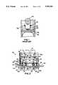
- FIG. 2is a partial front view of a pump apparatus according to the present invention.
- FIG. 3is a partial cross-sectional end view of the cam shaft and outlet valve shown in FIG. 2 along line 3--3.
- FIG. 4is a partial cross-sectional end view of the cam shaft and expulsor shown in FIG. 2 along line 4--4.
- FIG. 5is a partial cross-sectional end view of the cam shaft and inlet valve shown in FIG. 2 along line 5--5.
- FIG. 6is a free body diagram useful for solving for the resultant force applied by the cam to the follower in the energy and torque analysis.
- FIG. 7is a diagram useful for computing the resultant force when the follower motion is initially specified.
- FIG. 8is a diagram useful for computing the cam profile when the follower motion is initially specified.
- FIG. 9is a diagram useful for computing the resultant force when the cam profile is initially specified.
- FIG. 10is a diagram useful for computing the torques applied to the cam when the follower motion is initially specified.
- FIG. 11is a drawing useful for computing the torques applied to the cam when the cam profile is initially specified.
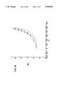
- FIG. 12is an example of one tube loading curve illustrating the tube loading necessary to compress the tube to a more compressed state in solid line, and the tube loading when the tube returns from the compressed state to a less compressed state in the dashed line.
- FIG. 13is an example of the cam profiles for an inlet valve cam, an expulsor cam, and an outlet valve cam resulting from a cam and follower design optimization for a pump.
- FIG. 14is an example of the torques applied to each of the inlet valve cam, the expulsor cam, and the outlet valve cam of FIG. 13 during one activation of the pump.
- FIG. 15is an example of the total torques applied to the cam shaft including the inlet valve cam, the expulsor cam, and the outlet valve cam of FIG. 13 during one activation of the pump.
- FIG. 16is a schematic diagram of a cam shaft design and manufacturing system.
- FIG. 1relates to a prior art pump apparatus 15, or pump, similar to that disclosed in U.S. Pat. No. 4,559,038, previously incorporated by reference.
- Pump 15includes a pressure plate 15a, a tube 15b, a follower 15c and a cam shaft with a cam 15d. By rotating cam 15d, the reciprocally mounted follower 15c compresses tube 15b against pressure plate 15a at varying amounts during rotation of cam 15d about a 360 degree span.
- Prior art pump 15fluid reservoir 15e supplies fluid to tube 15b. By appropriate movement of follower 15c, the fluid is pumped through tube 15b.
- follower 15ccan be a valve which opens and closes a fluid flow path through tube 15b.
- follower 15ccan instead be an expulsor which pushes on tube 15b to force fluid in the tube toward an open end of the tube, i.e. toward the patient.
- Prior art pump 15is an example of a peristaltic pump which has three tube-engaging members. In prior art pump 15, three cams like cam 15d, and three followers like follower 15c are provided. Operation of the three tube-engaging members in a peristaltic pump will be described in greater detail as they relate to the present invention.
- peristaltic type pumpsincluding a wave style peristaltic pump which includes a plurality of fingers which are reciprocally mounted. The fingers are reciprocally moved successively to engage and compress the tube in a wave pattern to pump fluid.
- the torque needed to rotate cam 15dis related to the force needed to compress tube 15b a predetermined amount.
- the torqueis related to: the tube properties during compression and expansion of tube 15b; the force applied to follower 15c by gasket 15f; the frictional forces applied by chassis 15g to follower 15c; and the frictional force applied by follower 15c to cam 15b.
- the energy needed to rotate cam 15d a predetermined amountis related to the amount of rotation of cam 15d when the torque is applied.
- Pump 20is particularly adapted for securement to a patient such as by a belt allowing the patient to be ambulatory while having continuous infusion of a drug at the desired rate.
- Pump 20generally includes a control module 20a, and a reservoir module 20b selectively attachable to control module 20a. In FIG. 2, only a portion of the control module 20a and a portion of reservoir module 20b are shown.
- Control module 20agenerally includes a pumping mechanism 26 and associated control structure (not shown) for controlling pumping mechanism 26.
- a housing(not shown) is provided to enclose pumping mechanism 26 and the control structure.
- a keypad(not shown) may be provided to access the control structure.
- Reservoir module 20bgenerally includes a tube 24 and means for supplying fluid to the tube, such as the bag-like reservoir 15e of FIG. 1, located at pump 20 or remotely to pump 20.
- pump 20includes a pressure plate 22.
- Pressure plate 22is generally associated with reservoir module 20b in one preferred embodiment.
- Tube 24Positioned between pump mechanism 26 and pressure plate 22 is tube 24.
- Pump mechanism 26interacts with tube 24 and pressure plate 22 to pump fluid through tube 24 at the appropriate rate. Pump mechanism 26 also restricts the free flow of fluid through tube 24 at all times.
- Pump mechanism 26includes a rotatable cam shaft 34.
- a chassis 28 with braces 30,32is provided for rotatably holding cam shaft 34.
- Cam shaft 34includes a first cam 40, a second cam 50, and a third cam 60.
- Pump mechanism 26further includes an inlet valve follower 80, an expulsor follower 90, and an outlet valve follower 100.
- Followers 80,90,100are reciprocally mounted to chassis 28 through apertures 70,72,74, respectively.
- Each of the followers 80,90,100is engageable with the respective cam 40,50,60 such that each follower is reciprocally movable in response to rotation of the respective cam.
- inlet valve follower 80includes a head portion 82 with an arcuate end 84 for engaging cam 40 along cam surface 42. Inlet valve follower 80 further includes an abutment surface 86 to maintain inlet valve follower 80 in aperture 70. Inlet valve follower 80 further includes a tip 88 for engaging tube 24 during reciprocal movement of inlet valve follower 80.
- expulsor follower 90includes a head portion 92 with an arcuate end 94 for engaging cam 50 along cam surface 52. Expulsor follower 90 further includes an abutment surface 96 to maintain expulsor follower 90 in aperture 72. Expulsor follower 90 further includes a surface 98, for engaging tube 24 during reciprocal movement of expulsor follower 90.
- outlet valve follower 100includes a head portion 102 with an arcuate end 104 for engaging cam 60 along cam surface 62. Outlet valve follower 100 further includes an abutment surface 106 to maintain inlet valve follower 100 in aperture 74. Outlet valve follower 100 further includes a tip 108, for engaging tube 24 during reciprocal movement of outlet valve follower 100.
- outlet valve follower 100compressing tube 24 closed
- expulsor follower 90 and inlet valve follower 80are positioned to allow tube 24 to fill with fluid from the fluid reservoir.
- Inlet valve follower 80compresses tube 24 closed and outlet valve follower 100 permits tube 24 to open at least partially to permit the passage of fluid to the patient.
- Expulsor follower 90compresses tube 24 to push the fluid past outlet valve follower 100 toward the patient.
- Outlet valve follower 100then compresses tube 24 closed to begin the pumping cycle again.
- a gasket 110is provided for biasing expulsor follower 90 and inlet and outlet valve followers 80,100 toward cams 40,50,60 and for sealing followers 80,90,100 between pressure plate 22 and an interior of control module 20a.
- Gasket 110includes appropriate apertures for receiving expulsor follower 90, inlet valve follower 80, and outlet valve follower 100.
- Pump 20includes means for turning gear 112, such as a motor and associated gearing 114.
- the motorcan be a DC motor that rotates cam shaft 34 a predetermined amount to activate pumping mechanism 26.
- the motoris activated the predetermined number of times or the predetermined duration necessary to pump the desired amount of fluid to the patient.
- chassis 28includes means for attaching the pressure plate 22 to position tube 24 for engagement by expulsor follower 90, inlet valve follower 80, and outlet valve follower 100.
- expulsor follower 90As disclosed in U.S. Pat. No. 4,559,038, previously incorporated by reference, an upraised portion and hinge pins may be provided with respect to chassis 28. These are complementary to and for hingedly receiving hooked portions extending from pressure plate 22.
- a lock memberis provided for selectively mounting the second end of pressure plate 22 to chassis 28.
- the power supply for the motormay include a replaceable battery, such as a conventional 9 volt battery.
- Suitable electronic controlsare provided for operation of the motor for controlling the pumping of fluid from the fluid reservoir through tube 24 to the patient at the desired rate. In some cases, patient control of the motor may be provided.
- the present pump 20is operable at 60 revolutions per minute.
- Low speed mechanismssuch as pump 20, often use specified cam profiles such as simple eccentric, harmonic, or circular-arc came, because of the low dynamic effects and the ease manufacturing.
- the tube force curveis nonlinear as the degree of compression changes.
- the simple eccentric, harmonic, Or circular-arc camsmay not be energy efficient with respect to power supply life given that the tube load is nonlinear and that the structures of the cam/follower and follower/chassis interfaces can produce relatively high frictional loads. Also, peak torques may be unnecessarily high due to the nonlinear tube loading.
- the pumping mechanism of the pump 20has been configured and arranged to minimize torques and energy consumption by analysis of the forces applied to the cam shaft 34, including a tube load which is nonlinear due to the shape of the tube and the manner the tube is compressed.
- a mathematical modelis provided for analyzing the torques and energies for a given design.
- the modelcalculates the resultant cam profile, and the cam radius of curvature. Optimization can then be done to determine optimal cam and follower profiles.
- the follower lift as a function of angular displacementis calculated for use in optimization.
- Important inputs to the modelinclude: the tube load as a function of tube deflection (including gasket load), the various coefficients of friction of the elements which slidably engage during operation, the various relevant dimensions of the follower and the chassis, the base circle radius of the cam, the amount of cam rotation for one activation, and either the follower lift motion as defined by an equation as a function of cam rotation, or a cam profile specified independently of the follower lift motion.
- This modelcan be used to analyze an existing pumping mechanism, and then design a more energy efficient version, with only the cam profiles and follower profiles being changed. Other variables can be changed in the model to optimize the design. It is to be appreciated that in some optimizations of existing pumps, there may only be improvements in energy consumption or peak torques, but not both when the existing design is compared to the new optimized design. Alternatively, the model is useful for designing a new pump that meets or is within preselected ranges of desired energy consumption limits and peak torque limits.
- the modelcomputes the energy into the system by incrementally calculating the torque required to rotate the cam shaft a predetermined amount, typically one pumping activation.
- the integral of the torque verses cam angular position curveis the energy required to produce one pumping activation.
- the energy outputsare also calculated at the various locations of sliding frictional contact, as well as the hysteresis losses in the pump tube.
- the tube loading input to the modelis dependent upon the tube properties, for example, the size and composition of the tube, as well as the shape and the size of the tube engaging portion of the follower.
- the force needed to compress the tube a predetermined amount with the tube engaging portion of the followercan be measured experimentally to develop the tube loading curve. Included in the tube loading curve is the force exerted by the gasket, like gasket 110 of FIG. 2, or other biasing structure which biases the follower away from the tube.
- One cam and follower design and manufacturing methodis provided wherein a follower motion is initially specified as a function of angular rotation of the cam.
- the shape of follower surface engaging the camis also specified.
- the pressure angle at the contact region between the cam and followeris needed to calculate the resultant force acting on the cam.
- the pressure angleis solved for as a function of the angular rotation of the cam.
- the resultant force applied by the cam to the followeris solved for as a function of the angular rotation of the cam.
- Inputs to the resultant force equationinclude: the coefficient of friction of the cam and chassis interface, the shape of the cam engaging portion of the follower, the follower height, the follower width, the base circle radius of the cam, the amount of cam rotation for one activation, the chassis thickness, the distance from the center of the cam to the top of the chassis, and the tube load (including gasket load applied to the follower).
- the torqueis calculated as a function of the angular displacement of the cam.
- An input to this analysisis the coefficient of friction for the cam and follower interface.
- a graph of torque versus angular displacement of the camcan be made to visually note magnitude and location of peak torque values.
- the area under the torque versus angular displacement curveis equal to an energy consumed value to rotate the cam a particular amount of angular displacement. If more than one cam is provided on the cam shaft, a graph of total torque applied to the cam shaft may be made to visually note the magnitude and location of the total peak torque values.
- the separate energy componentsincluding the energy consumed by the frictional losses between the cam and follower and between the follower and the chassis can be calculated. Hysteresis losses can also be calculated with respect to the tube. When calculated, all of these energy components help the optimization process by isolating particular energy losses.
- the optimization processproceeds by changing one or more variables to reduce one or both of the values obtained for energy consumption and peak torque loads. It has been found to be a useful technique to lower the energy consumption value as low as possible within preselected design constraints, and then reduce the peak torque value to the lowest possible value within the preselected design constraints. Once an optimized design is determined, the design parameters are utilized to manufacture an energy efficient pump including the optimized cam and follower design.
- the optimization processcan be done experimentally such as by trial and error utilizing a computer where one or more selected variables are changed and then the computer outputs data regarding the peak torques and the energy consumed to rotate the cam.
- the optimization of selected variablescan be done utilizing mathematical techniques, such as a Taguchi technique.
- the free body diagram of a follower 200which can be used for the analysis of the input and output valve followers 90,100 and for the expulsor follower 80 for pump 20, or the cams and followers of other pumps with tube engaging members.
- the free body diagramanalyzes the forces acting on the follower 200 including the resultant force F applied by the cam.
- the gravitational forcehas been omitted because it is several orders of magnitude less than the pump tube deflection force with respect to pump 20. For the same reason, the inertial force may be omitted unless the follower accelerations become much greater than 1 g. From the free body diagram: ##EQU1##
- Force Fis the resultant force of the normal force F n and the frictional force f.
- the follower lift, the follower acceleration and the pressure anglemust first be known.
- the liftis used to solve for h 1 and h 2
- the pressure angleis used to solve for dx and dy,
- h 1 and h 2depend on the direction and location of resultant force F. Whichever way the follower tends to rotate will have the lower h value, and this depends on whether ⁇ (combined pressure and friction angle) is greater or less than arctan (dx/(ht-dy),
- ctctotal height from center of cam to top of chassis 202
- cthchassis thickness of chassis 202
- One of the primary design concernsis minimizing the required cam shaft input torque for a specified follower motion. Minimizing contact forces to minimize wear is also a main concern. High contact forces lead to high input torques.
- the input torqueis affected by the pressure angle on the cam and the inertial loading from high accelerations and large follower masses.
- the pressure angleis the angle between the direction of follower motion and the normal to the contact between the cam and the follower. The pressure angle is in effect a measure of the mechanical advantage of the system.
- Follower motion optimizationis a balance between minimizing accelerations and minimizing pressure angles. For example, if the acceleration is minimized at the start of the lift motion, the velocity must increase slowly, and therefore must reach a higher maximum somewhere during the lift, to achieve the same total lift over the same duration. This raises the pressure angle at some point during cam rotation. The lowest possible velocity and pressure angle would be achieved with a constant velocity of L/ ⁇ , (where L is total follower lift, and ⁇ is total angular duration), but the initial and final accelerations would be infinite. In pump 20, the rotational masses are approximately one gram, so the inertial loading is very low. If the rotational speeds and follower masses were greater, then the accelerations would have to be further minimized at the expense of higher maximum pressure angles.
- the cam and follower designcan be optimized by analyzing the impact of the pressure angle of the energies and torques.
- a polynomial curve of follower motionis provided that permits setting the velocity at the start and finish of the lift curve as well as setting the maximum velocity at any specified point during the lift. This allows tailoring the follower lift curve to the nonlinear tube loading so that during low loads the velocity is high, and later during high loads the velocity and pressure angle are minimized.
- the polynomial follower lift curvecan be calculated in a normalized reference system where total lift and angular duration are 1.
- the polynomialis formed by using the following boundary conditions: ##EQU3## By substituting these conditions into the following equation for lift s, a system of equations can be formed and solved for the unknown coefficients a 0 to a 5 .
- the cam and follower modeling programcan be set up to solve this system of equations, using the above variables Vo, Vf, K, and Vmax, so that by simply changing these variables new motion polynomial curves can be generated. These motions can be then input into the model to determine the effect on mechanism forces, torques, and energies.
- the pressure angles and cam profilesare determined for the specified follower motion. Determining the pressure angle ⁇ depends on whether the follower motion is specified, or in the less common instance if the cam profile itself is specified.
- cam profileis computed as follows:
- the pressure angle and follower liftmust be determined.
- the distance R for the cam profileis known as a function of some angle ⁇ , and it is desired to know the follower lift s and pressure angle ⁇ , both as a function of ⁇ . Referring to FIG. 9:
- ⁇ cis the coefficient of friction between the cam and the follower
- the E out termscan be evaluated as follows, using trapezoidal integration techniques to compute the individual energy loss components:
- the coefficients of frictioncan be experimentally determined, if not known, by using a force gauge to pull a weighted specimen of follower material across both chassis material and cam material.
- Tube loading P(s)can be determined experimentally in an existing pump, like pump 15, by measuring the forces necessary to lift the inlet and outlet valves and the expulsor to various heights. This can be accomplished by drilling small holes through the cam shaft of prior art pump 15 at the valves and expulsor locations. Free fitting pins can be installed along with set screws to lock the pins in any position. The cam is then reassembled in a chassis which is then latched to a reservoir module with a pressure plate. The pins are pushed through the cam with a force gauge and locked, after which the reservoir module is removed and the valve or expulsor heights measured. This is repeated at various increments. The forces can also be measured as the tube is unloaded, to give an indication of any hysteresis effects. Polynomials can then be curve fit to the data and then used in the model for the tube load P(s).
- the cam and follower design optimization and modelingcan be performed using Microsoft Excel software.
- Excel softwareallows fairly fast running and re-plotting of torque graphs and cam profiles, as lift motions and cam and follower dimensions are changed.
- Other high level programming languagessuch as Fortran or Basic could be utilized to optimize the design.
- cam profile x-y coordinate data filescan be generated using Basic, and these data files can be used to drive CNC cam grinding equipment to manufacture the cam of the optimized design and/or materials.
- the follower designcan be manufactured from a variety of materials and processes with the optimized dimensions and/or materials.
- One method of design optimizationis to vary the follower shape to reduce frictional loads applied to the follower by the chassis until an optimal design is achieved.
- the side load frictional lossescan be minimized by providing a radius of curvature on the "roller" section of the follower 200 which is convex as shown in FIG. 7, for example, instead of concave as shown in prior art pump 15. If the cam contact force F is directed toward the center of the pump tube contact area, then high side loads from chassis 202 are not present to prevent rotation of the follower 200. If the force F is away from the pump tube, then the side loads and frictional losses will be higher.
- the arcuate portion 84,94,104 of each follower 80,90,100is preferably a convex radius.
- a further method of design optimizationis to vary the base circle radius of the cam and/or the amount of cam rotation for one activation until an optimal design is achieved.
- the cam contact frictional lossescan be minimized by reducing the distance traveled on the cam, for a given ⁇ c . This is possible by either reducing the base circle radius or the overall amount of cam rotation required for one pumping activation.
- the differential ds part of the ⁇ c F n ds termis equivalent to rd ⁇ , so the distance can be reduced by reducing either the radius r or the angular duration d ⁇ .
- the pressure anglewill increase, so for a given maximum pressure angle (usually 30 deg) there is a minimum base circle radius.
- Peak torquescan be controlled by changing the lift duration, and lift motion. For a given lift duration and the preferred tube 24, the peak torques can be minimized by appropriate setting of the maximum lift velocity. The initial and final velocities can be left equal to zero.
- the present inventionrelates particularly to a method of design optimization and manufacturing of a cam and a follower for a peristaltic pump having a compressible tube, where the method comprises the steps of: selecting a cam and follower design D n including the parameters needed to calculate torques and energies applied to the cam to move the follower; and obtaining a tube force loading curve indicative of the force applied to the tube which is necessary to compress the tube with the cam and follower design D n .
- the tube force loading curvemay change as the tube properties change and/or the shape of the follower surface engaging the tube changes. If those features remain constant in the design optimization, then this data need only be measured or obtained once.
- the methodfurther includes computing a torque curve or torque data to permit identification of a peak torque value and an energy consumed value for the cam and follower design D n .
- the peak torque value and the energy consumed value for the cam and follower design D nare optimized by varying one or more of the following parameters: the follower shape, the amount of cam rotation for one activation, the follower motion, and the cam base circle radius for a different cam and follower design D n+1 . Still other parameters affecting peak torques and energies can be changed to optimize the design. The optimization proceeds with still further different cam and follower designs D n+2 , etc. Once the peak torque value and the energy consumed value for the selected cam and follower design D n , D n+1 , or D n+2 , etc.
- a cam and a followerare manufactured with the optimized cam and follower design parameters.
- the above methodis useful for simultaneously analyzing a plurality of cams on a single cam shaft and a plurality of followers, as in a peristaltic pump having an expulsor and inlet and outlet valves.
- the present inventionalso relates particularly to a method of design optimization and manufacturing of a cam and a follower for a pump having a compressible tube to improve the performance of an existing pump, where the method comprises the steps of: obtaining an energy consumed value for one activation of the existing pump; and obtaining torque data during one activation of the existing pump. This can be done experimentally by measuring peak power demand and power supply life. Power usage can be measured with an oscilloscope.
- the methodfurther comprises selecting a new cam and follower design D n for the pump. A tube force loading curve indicative of the force applied to the tube which is necessary to compress the tube with the cam and follower design D n is measured or obtained.
- the tube force loading curvemay vary if the tube properties are changed or if the shape of the follower surface engaging the tube is changed.
- Torque data indicative of the torques applied to the cam to move the follower through the follower motion using the tube force loading curveis calculated.
- the energy consumed to rotate the cam to move the follower design through the follower motion using the tube force loading curveis calculated.
- the torque data and the energy consumed for the cam and follower design D nis compared to the torque data and the energy consumed value for the existing pump.
- the cam and follower design D nis optimized by selecting different new cam and follower designs D n+1 , D n+2 , etc. Once optimized, a cam and a follower is manufactured using the optimized cam and follower design parameters.
- Radius of all of the arcuate ends 84,94,104 of followers 80,90,1000.25 inches.
- Length of arcuate ends 84,104 of followers 80,1000.367 inches.
- Length of arcuate end 94 of follower 900.796 inches.
- Tips 88,108 of followers 80,100a dimension of 0.434 inches in the transverse direction relative to tube 24, with radiused ends of 0.031 inches, and each tip being formed by planar surfaces each at 40 degrees to the horizontal and interconnected by a curved radial surface of 0.047 inches.
- surface 98 of follower 90a generally planar surface of 0.657 inches in the direction of tube 24 and 0.434 inches in the transverse direction relative to tube 24, with radiused corners of 0.093 inches.
- Tube 24has the following properties:
- the tube loading curvewas experimentally measured by repeating the pin process described above at 0.5 lb increments and resulting in data like that shown in FIG. 12 for the expulsor of an existing pump, a CADD-1TM pump, with 50 microliters per activation, by Pharmacia Deltec, of St. Paul, Minn.
- Tube load equation for expulsor, curve fit from measured data: Force to compress tube and gasket approximately1.384+59.457s+76637s 4
- Gasket 110is made from a closed cell urethane foam approximately 0.18 in thick.
- the maximum lift velocitywas set to approximately 1.6 L/ ⁇ at 0.25 ⁇ for the expulsor.
- the maximum lift velocitywas set to approximately 1.8 L/ ⁇ at 0.25 ⁇ for the inlet valve.
- the maximum lift velocitywas set to approximately 1.9 L/ ⁇ at 0.23 ⁇ for the outlet valve.
- the maximum fall velocitywas set to approximately 1.6 L/ ⁇ at 0.3 ⁇ for the expulsor and the inlet and outlet valves.
- FIG. 13shows a graph of the cam profiles for cam surfaces 42,52,62.
- FIG. 14shows a graph of the torques applied to each cam turning one activation of pump 20.
- FIG. 15shows a graph of the total torque applied to all three cams during one activation of pump 20.
- the methodscan be employed to optimize the new mechanism design over the prior design shown in FIG. 1.
- the follower profilewas changed from concave to convex to lower the side load energy losses by making the follower radius as large as possible without causing undercutting.
- the follower motionwas designed to reduce peak torques by moving the maximum velocity location.
- the cam-follower contact losseswere reduced by completing an activation in 180 degrees.
- the base circle radiuswas reduced.
- the inlet and outlet valve followers and the expulsor followerwere lengthened.
- the new more energy efficient cam and follower design of pump 20only requires different cam and follower profiles over prior art pump 15, so the tube, the foam pad, the chassis dimensions, and the coefficients of friction all remain the same.
- the new energy efficient mechanismcompletes an activation in 180 degrees, rather than 360 degrees, with essentially the same peak torques.
- the energy consumptionis reduced by approximately 50% and volumes delivered were almost doubled (approximately 1700 ml per 9 volt battery for pump 20, and approximately 900 ml per 9 volt battery for pump 15).
- a method of manufacturing a cam and a follower for a peristaltic pump having a compressible tubecomprises the steps of: selecting an initial cam and follower design D n ; obtaining tube force data indicative of the force applied to the tube which is necessary to compress the tube with the cam and follower design D n ; calculating torque data indicative of the torques applied to the cam; calculating the energy consumed to rotate the cam; comparing the torque data and the energy consumed for the cam and follower design D n to desired torque data and a desired energy consumed value; if the torque data and the energy consumed for the cam and follower design D n is not lower than or within a preselected range (set by the user) of the desired torque data and the desired energy consumed value, then selecting one or more different cam and follower designs D n+1 , D n+2 , etc., and calculating torque data and an energy consumed value for the
- the optimization of the cam and follower design Dnincludes optimization of preselected parameters such as follower shape, follower motion, cam base circle radius, and cam rotation for one activation, and other parameters.
- the methodmay further comprise the optimization of the design and manufacture of a cam and follower design including a plurality of cams and followers.
- System 140includes a computer 150, such as a conventional personal computer, with a processor and associated electronic memory. Electrically interconnected to computer 150 is a display 160 and a keyboard 170 for inputting user commands to computer 150. Display 160 is useable to display user prompts and/or outputs of the computer 150, such as numerical data and graphical data.
- cam grinding mechanism 180for grinding a cam shaft based upon inputs received from computer 150.
- Cam grinding mechanism 180can be a CNC cam grinding equipment or other equipment to grind a cam shaft from metal stock.
- Computer 150includes programs which permit analysis and optimization of proposed cam and follower designs for pump 20.
- computer 150is programmed by the user with various proposed design parameters, or the computer prompts the user to input one or more proposed design parameters.
- Computer 150includes appropriate programs to calculate torque data indicative of the torques applied to the cam shaft of the proposed cam and follower design during operation. The torque data is useable to identify peak torque loads.
- computer 150includes appropriate programs for calculating energy consumed values indicative of the energy consumed to rotate the cam shaft of the cam and follower design a predetermined amount. This may include total energy consumed and the separate components that comprise the total energy consumed.
- a user of computer 150can study the outputs of the various programs on display 160, and then make one or more changes to the proposed design parameters to optimize the cam and follower design.
- cam grinding mechanism 180where the cam profile or profiles are ground at cam grinding mechanism 180.
- the follower or followerscan be manufactured by various processes utilizing the optimized design parameters, such as injection molding.
- computer 150permits a user to input the design parameters of: a specified shape for a follower surface of each follower for engaging a cam, a specified follower motion for each of the followers, a specified cam base circle radius for each of the cams, and a specified cam shaft rotation amount. Other variables can be input by the user during the design optimization.
- Computer 150preferably permits analysis of a plurality of cams on each cam shaft.
- a first programbe provided for displaying the torques applied to each cam of the cam shaft in graphical format.
- a second programmay be provided for displaying the total torques applied to the cam shaft in graphical format.
- a third programmay be provided for displaying a profile of the proposed cam in graphical format.
Landscapes
- Engineering & Computer Science (AREA)
- Mechanical Engineering (AREA)
- General Engineering & Computer Science (AREA)
- Infusion, Injection, And Reservoir Apparatuses (AREA)
Abstract
Description
dx=r.sub.f sin α
dy=r.sub.f (1-cos α)
h.sub.1 =ctc-cth-r.sub.b -s, if φ>arctan (dx/(ht-dy)), else h.sub.1 =ctc-r.sub.b -s
h.sub.2 =ctc-r.sub.b -s, if φ>arctan (dx/(ht-dy)), else h.sub.2 =ctc-cth-r.sub.b -s
s=a.sub.0 +a.sub.1 Θ+a.sub.2 Θ.sup.2 +a.sub.3 Θ.sup.3 +a.sub.4 Θ.sup.4 +a.sub.5 Θ.sup.5
L=r.sub.b +s+r.sub.f
R.sub.x =(r.sub.b +r.sub.f +s) cos Θ-r.sub.f cos (α-Θ)
R.sub.y =(r.sub.b +r.sub.f +s) sin Θ-r.sub.f sin (α-Θ)
R=r.sub.b +s',
L.sup.2 =R.sup.2 +r.sub.f -2Rr.sub.f cos (π-ψ)
Lift of follower s=L-r.sub.b -r.sub.f
χ=π-α-(π-ψ)=ψ-α
and, Θ=β-χ.
E.sub.in =∫TdΘ
E.sub.out =∫μ.sub.c F.sub.n ds+∫μ.sub.f N.sub.1 ds+∫μ.sub.f N.sub.2 ds+∫P(s)ds.
λ=arctan μ.sub.c
λ=arctan μ.sub.c
R=r.sub.b +s'
T=RF sin (ψ+λ).
TABLE 1 ______________________________________ INLET VALVE CAM PROFILE Motion Radius in inches Angle of rotation θ ______________________________________ Dwell .165 0°-2° &ADD 180° Rise Poly-curve 2°-42° Dwell .213 42°-142° Fall Poly-curve 142°-178° Dwell .165 178°-180° ______________________________________
TABLE 2 ______________________________________ EXPULSOR CAM PROFILE Motion R θ ______________________________________ Dwell .165 0°-36° &ADD 180° Rise Poly-curve 36°-109° Dwell .2275 109°-137° Fall Poly-curve 137°-175° Dwell .165 175°-180° ______________________________________
TABLE 3 ______________________________________ OUTLET VALVE CAM PROFILE Motion R θ ______________________________________ Dwell .213 0°-28° &ADD 180° Fall Poly-curve 28°-64° Dwell .165 64°-102.5° Rise Poly-curve 102.5°-155.5° Dwell .213 155.5°-180° ______________________________________
Claims (7)
Priority Applications (1)
| Application Number | Priority Date | Filing Date | Title |
|---|---|---|---|
| US07/981,832US5364242A (en) | 1992-11-25 | 1992-11-25 | Pump apparatus and method including double activation pump apparatus |
Applications Claiming Priority (1)
| Application Number | Priority Date | Filing Date | Title |
|---|---|---|---|
| US07/981,832US5364242A (en) | 1992-11-25 | 1992-11-25 | Pump apparatus and method including double activation pump apparatus |
Publications (1)
| Publication Number | Publication Date |
|---|---|
| US5364242Atrue US5364242A (en) | 1994-11-15 |
Family
ID=25528683
Family Applications (1)
| Application Number | Title | Priority Date | Filing Date |
|---|---|---|---|
| US07/981,832Expired - LifetimeUS5364242A (en) | 1992-11-25 | 1992-11-25 | Pump apparatus and method including double activation pump apparatus |
Country Status (1)
| Country | Link |
|---|---|
| US (1) | US5364242A (en) |
Cited By (60)
| Publication number | Priority date | Publication date | Assignee | Title |
|---|---|---|---|---|
| US5564915A (en)* | 1993-10-28 | 1996-10-15 | Sims Deltec, Inc. | Pressure plate for pump and reservoir enclosure |
| US5567136A (en)* | 1993-10-28 | 1996-10-22 | Sims Deltec, Inc. | Pressure plate for pump and reservoir enclosure |
| GB2338759A (en)* | 1996-04-10 | 1999-12-29 | Baxter Int | Infusion pump valve with rounded vertex |
| US6077055A (en)* | 1998-12-03 | 2000-06-20 | Sims Deltec, Inc. | Pump system including cassette sensor and occlusion sensor |
| US6189736B1 (en) | 1997-01-17 | 2001-02-20 | Niagara Pump Corporation | Condiment dispensing apparatus |
| EP1101504A2 (en) | 1996-04-10 | 2001-05-23 | Baxter International Inc. | Volumetric infusion pump automatic tube loading apparatus |
| US20020198494A1 (en)* | 2001-02-23 | 2002-12-26 | Diaz Luis A. | Port assembly for an integrated medication delivery system |
| US20030181866A1 (en)* | 2002-03-21 | 2003-09-25 | Kent Abrahamson | Pump and tube set thereof |
| US6666665B1 (en)* | 1999-03-04 | 2003-12-23 | Baxter International Inc. | Fluid delivery mechanism having a plurality of plungers for compressing a metering chamber |
| US20040034331A1 (en)* | 2001-02-23 | 2004-02-19 | Jason Toman | Integrated medication delivery system |
| US20050033245A1 (en)* | 2002-03-21 | 2005-02-10 | Kent Abrahamson | Pump and tube set thereof |
| US20070289659A1 (en)* | 2006-06-16 | 2007-12-20 | Maguire Stephen B | Liquid color gravimetric metering apparatus and methods |
| US20070292288A1 (en)* | 2006-06-16 | 2007-12-20 | Maguire Stephen B | Multiple pusher liquid color pump |
| US7530968B2 (en) | 2003-04-23 | 2009-05-12 | Valeritas, Inc. | Hydraulically actuated pump for long duration medicament administration |
| US7914499B2 (en) | 2006-03-30 | 2011-03-29 | Valeritas, Inc. | Multi-cartridge fluid delivery device |
| CN102022301A (en)* | 2010-11-26 | 2011-04-20 | 大连依利特分析仪器有限公司 | Three camshafts for large flow high pressure constant flow pump |
| US7980834B2 (en) | 2006-06-16 | 2011-07-19 | Maguire Stephen B | Liquid color injection pressure booster pump and pumping methods |
| US20110200464A1 (en)* | 2010-02-16 | 2011-08-18 | Maguire Paul Sherwood | Method and disposable low-cost pump in container for liquid color dispensing |
| US8016789B2 (en) | 2008-10-10 | 2011-09-13 | Deka Products Limited Partnership | Pump assembly with a removable cover assembly |
| US8034026B2 (en) | 2001-05-18 | 2011-10-11 | Deka Products Limited Partnership | Infusion pump assembly |
| US8066672B2 (en) | 2008-10-10 | 2011-11-29 | Deka Products Limited Partnership | Infusion pump assembly with a backup power supply |
| US8092070B2 (en) | 2006-06-17 | 2012-01-10 | Maguire Stephen B | Gravimetric blender with power hopper cover |
| US20120078182A1 (en)* | 2010-09-24 | 2012-03-29 | Smith Roger E | Infusion pumps |
| US8223028B2 (en) | 2008-10-10 | 2012-07-17 | Deka Products Limited Partnership | Occlusion detection system and method |
| US8262616B2 (en) | 2008-10-10 | 2012-09-11 | Deka Products Limited Partnership | Infusion pump assembly |
| US8267892B2 (en) | 2008-10-10 | 2012-09-18 | Deka Products Limited Partnership | Multi-language / multi-processor infusion pump assembly |
| US8287495B2 (en) | 2009-07-30 | 2012-10-16 | Tandem Diabetes Care, Inc. | Infusion pump system with disposable cartridge having pressure venting and pressure feedback |
| US8708376B2 (en) | 2008-10-10 | 2014-04-29 | Deka Products Limited Partnership | Medium connector |
| US8974415B2 (en) | 2012-04-10 | 2015-03-10 | Smiths Medical Asd, Inc. | Flow stop insert apparatus and methods |
| US8986253B2 (en) | 2008-01-25 | 2015-03-24 | Tandem Diabetes Care, Inc. | Two chamber pumps and related methods |
| US9089636B2 (en) | 2004-07-02 | 2015-07-28 | Valeritas, Inc. | Methods and devices for delivering GLP-1 and uses thereof |
| US9173996B2 (en) | 2001-05-18 | 2015-11-03 | Deka Products Limited Partnership | Infusion set for a fluid pump |
| US9180243B2 (en) | 2013-03-15 | 2015-11-10 | Tandem Diabetes Care, Inc. | Detection of infusion pump conditions |
| US9180245B2 (en) | 2008-10-10 | 2015-11-10 | Deka Products Limited Partnership | System and method for administering an infusible fluid |
| US9188118B2 (en) | 2012-06-15 | 2015-11-17 | Stephen B. Maguire | Injection molded diaphragm pump for liquid color with quick release |
| US9498573B2 (en) | 2010-09-24 | 2016-11-22 | Perqflo, Llc | Infusion pumps |
| US9555186B2 (en) | 2012-06-05 | 2017-01-31 | Tandem Diabetes Care, Inc. | Infusion pump system with disposable cartridge having pressure venting and pressure feedback |
| US9599265B2 (en) | 2012-06-15 | 2017-03-21 | Stephen B. Maguire | Multiple plate quick disconnect sandwich fitting |
| US9637283B2 (en) | 2012-06-15 | 2017-05-02 | Stephen B. Maguire | Quarter turn adapter connective outlet fitting for liquid color dispensing |
| US9662437B2 (en) | 2014-04-28 | 2017-05-30 | Smiths Medical Asd, Inc. | Infusion pump pressure plate |
| US9708462B2 (en) | 2013-07-17 | 2017-07-18 | Stephen B. Maguire | Liquid color composition with cottonseed oil base |
| US9796123B2 (en) | 2013-12-13 | 2017-10-24 | Stephen B. Maguire | Dripless liquid color feed throat adaptor and method for dripless liquid color delivery |
| US9841010B2 (en) | 2014-02-14 | 2017-12-12 | Stephen B. Maguire | Method and apparatus for closed loop automatic refill of liquid color |
| US9850888B2 (en) | 2012-06-15 | 2017-12-26 | Stephen B. Maguire | Molded diaphragm liquid color pump |
| US9962486B2 (en) | 2013-03-14 | 2018-05-08 | Tandem Diabetes Care, Inc. | System and method for detecting occlusions in an infusion pump |
| US10029045B2 (en) | 2010-11-20 | 2018-07-24 | Perqflo, Llc | Infusion pumps |
| US10138075B2 (en) | 2016-10-06 | 2018-11-27 | Stephen B. Maguire | Tower configuration gravimetric blender |
| US10159786B2 (en) | 2014-09-30 | 2018-12-25 | Perqflo, Llc | Hybrid ambulatory infusion pumps |
| US10201915B2 (en) | 2006-06-17 | 2019-02-12 | Stephen B. Maguire | Gravimetric blender with power hopper cover |
| US10258736B2 (en) | 2012-05-17 | 2019-04-16 | Tandem Diabetes Care, Inc. | Systems including vial adapter for fluid transfer |
| US10272196B2 (en) | 2010-09-24 | 2019-04-30 | Perqflo, Llc | Infusion pumps |
| US10597513B2 (en) | 2013-07-17 | 2020-03-24 | Stephen B. Maguire | Cottonseed oil based additive compositions for plastics molding and extrusion |
| US11131282B2 (en)* | 2019-03-01 | 2021-09-28 | Denso Corporation | Fuel injection pump |
| US11619221B2 (en)* | 2017-05-18 | 2023-04-04 | Keymed (Medical & Industrial Equipment) Limited | Peristaltic pump |
| US11672909B2 (en) | 2016-02-12 | 2023-06-13 | Medtronic Minimed, Inc. | Ambulatory infusion pumps and assemblies for use with same |
| US11684712B2 (en) | 2015-02-18 | 2023-06-27 | Medtronic Minimed, Inc. | Ambulatory infusion pumps and reservoir assemblies for use with same |
| US11795297B2 (en) | 2013-07-17 | 2023-10-24 | Stephen B. Maguire | Plastics coloring using cottonseed oil-based liquid color compositions |
| US12178992B2 (en) | 2014-09-30 | 2024-12-31 | Medtronic Minimed, Inc. | Different disposable assemblies for the same reusable assembly |
| US12186531B2 (en) | 2008-10-10 | 2025-01-07 | Deka Products Limited Partnership | Infusion pump assembly |
| US12370327B2 (en) | 2008-10-10 | 2025-07-29 | Deka Products Limited Partnership | Infusion pump methods, systems and apparatus |
Citations (22)
| Publication number | Priority date | Publication date | Assignee | Title |
|---|---|---|---|---|
| DE242874C (en)* | ||||
| US1480256A (en)* | 1919-09-19 | 1924-01-08 | Major E Gates | Fluid-controlling device |
| US2423701A (en)* | 1945-01-01 | 1947-07-08 | Marquette Metal Products Co | Pump |
| GB783971A (en)* | 1954-09-27 | 1957-10-02 | Licencia Talalmanyokat | Fuel injection pumps |
| US2813523A (en)* | 1953-10-29 | 1957-11-19 | Bosch Arma Corp | Fuel injection pump |
| US2871796A (en)* | 1955-08-02 | 1959-02-03 | Allis Chalmers Mfg Co | Pilot injection pump |
| US3371610A (en)* | 1966-02-16 | 1968-03-05 | Bosch Arma Corp | Auxiliary filling means for fuel injection pumps |
| US4017220A (en)* | 1975-10-30 | 1977-04-12 | William Hotine | Reversible pump with positive valving |
| US4352296A (en)* | 1980-09-18 | 1982-10-05 | General Motors Corporation | Chatter free gear driven cam actuated vacuum pump |
| US4535641A (en)* | 1981-06-13 | 1985-08-20 | Lucas Industries Plc | Reciprocating plunger fuel injection pump |
| US4559038A (en)* | 1984-10-19 | 1985-12-17 | Deltec Systems, Inc. | Drug delivery system |
| US4565542A (en)* | 1984-10-19 | 1986-01-21 | Deltec Systems, Inc. | Locking mechanism for a drug delivery system |
| US4650469A (en)* | 1984-10-19 | 1987-03-17 | Deltec Systems, Inc. | Drug delivery system |
| US4680930A (en)* | 1983-12-05 | 1987-07-21 | Otis Engineering Corporation | Hydraulic control circuit and valve assembly |
| US4681513A (en)* | 1985-02-01 | 1987-07-21 | Jeol Ltd. | Two-stage pump assembly |
| US4687426A (en)* | 1984-07-31 | 1987-08-18 | Fuji Techno Kogyo Kabushiki Kaisha | Constant volume pulsation-free reciprocating pump |
| US4730992A (en)* | 1986-03-26 | 1988-03-15 | Neuberg Company Limited | Continuously operable hydraulic device |
| US4791327A (en)* | 1985-08-06 | 1988-12-13 | U.S. Philips Corp. | Drive mechanism for a domestic vibration apparatus |
| US4803889A (en)* | 1986-07-11 | 1989-02-14 | Lucas Industries Public Limited Company | Fuel injection pump |
| US5017059A (en)* | 1988-05-17 | 1991-05-21 | Patient Solutions, Inc. | Infusion device with disposable elements |
| US5127907A (en)* | 1990-12-06 | 1992-07-07 | Abbott Laboratories | System for eliminating or reducing static electricity in infusion pumping systems |
| US5165873A (en)* | 1989-10-10 | 1992-11-24 | Imed Corporation | Two-cycle peristaltic pump |
- 1992
- 1992-11-25USUS07/981,832patent/US5364242A/ennot_activeExpired - Lifetime
Patent Citations (22)
| Publication number | Priority date | Publication date | Assignee | Title |
|---|---|---|---|---|
| DE242874C (en)* | ||||
| US1480256A (en)* | 1919-09-19 | 1924-01-08 | Major E Gates | Fluid-controlling device |
| US2423701A (en)* | 1945-01-01 | 1947-07-08 | Marquette Metal Products Co | Pump |
| US2813523A (en)* | 1953-10-29 | 1957-11-19 | Bosch Arma Corp | Fuel injection pump |
| GB783971A (en)* | 1954-09-27 | 1957-10-02 | Licencia Talalmanyokat | Fuel injection pumps |
| US2871796A (en)* | 1955-08-02 | 1959-02-03 | Allis Chalmers Mfg Co | Pilot injection pump |
| US3371610A (en)* | 1966-02-16 | 1968-03-05 | Bosch Arma Corp | Auxiliary filling means for fuel injection pumps |
| US4017220A (en)* | 1975-10-30 | 1977-04-12 | William Hotine | Reversible pump with positive valving |
| US4352296A (en)* | 1980-09-18 | 1982-10-05 | General Motors Corporation | Chatter free gear driven cam actuated vacuum pump |
| US4535641A (en)* | 1981-06-13 | 1985-08-20 | Lucas Industries Plc | Reciprocating plunger fuel injection pump |
| US4680930A (en)* | 1983-12-05 | 1987-07-21 | Otis Engineering Corporation | Hydraulic control circuit and valve assembly |
| US4687426A (en)* | 1984-07-31 | 1987-08-18 | Fuji Techno Kogyo Kabushiki Kaisha | Constant volume pulsation-free reciprocating pump |
| US4650469A (en)* | 1984-10-19 | 1987-03-17 | Deltec Systems, Inc. | Drug delivery system |
| US4565542A (en)* | 1984-10-19 | 1986-01-21 | Deltec Systems, Inc. | Locking mechanism for a drug delivery system |
| US4559038A (en)* | 1984-10-19 | 1985-12-17 | Deltec Systems, Inc. | Drug delivery system |
| US4681513A (en)* | 1985-02-01 | 1987-07-21 | Jeol Ltd. | Two-stage pump assembly |
| US4791327A (en)* | 1985-08-06 | 1988-12-13 | U.S. Philips Corp. | Drive mechanism for a domestic vibration apparatus |
| US4730992A (en)* | 1986-03-26 | 1988-03-15 | Neuberg Company Limited | Continuously operable hydraulic device |
| US4803889A (en)* | 1986-07-11 | 1989-02-14 | Lucas Industries Public Limited Company | Fuel injection pump |
| US5017059A (en)* | 1988-05-17 | 1991-05-21 | Patient Solutions, Inc. | Infusion device with disposable elements |
| US5165873A (en)* | 1989-10-10 | 1992-11-24 | Imed Corporation | Two-cycle peristaltic pump |
| US5127907A (en)* | 1990-12-06 | 1992-07-07 | Abbott Laboratories | System for eliminating or reducing static electricity in infusion pumping systems |
Cited By (113)
| Publication number | Priority date | Publication date | Assignee | Title |
|---|---|---|---|---|
| US5567136A (en)* | 1993-10-28 | 1996-10-22 | Sims Deltec, Inc. | Pressure plate for pump and reservoir enclosure |
| US5564915A (en)* | 1993-10-28 | 1996-10-15 | Sims Deltec, Inc. | Pressure plate for pump and reservoir enclosure |
| GB2338759A (en)* | 1996-04-10 | 1999-12-29 | Baxter Int | Infusion pump valve with rounded vertex |
| EP1101504A2 (en) | 1996-04-10 | 2001-05-23 | Baxter International Inc. | Volumetric infusion pump automatic tube loading apparatus |
| EP1101503A2 (en) | 1996-04-10 | 2001-05-23 | Baxter International Inc. | Volumetric infusion pump drive apparatus |
| SG85654A1 (en)* | 1996-04-10 | 2002-01-15 | Baxter Int | Volumetric infusion pump |
| EP1251276A2 (en) | 1996-04-10 | 2002-10-23 | Baxter International Inc. | Volumetric infusion pump |
| US6189736B1 (en) | 1997-01-17 | 2001-02-20 | Niagara Pump Corporation | Condiment dispensing apparatus |
| US6213739B1 (en) | 1997-01-17 | 2001-04-10 | Niagara Pump Corporation | Linear peristaltic pump |
| US6077055A (en)* | 1998-12-03 | 2000-06-20 | Sims Deltec, Inc. | Pump system including cassette sensor and occlusion sensor |
| US6666665B1 (en)* | 1999-03-04 | 2003-12-23 | Baxter International Inc. | Fluid delivery mechanism having a plurality of plungers for compressing a metering chamber |
| US20060282040A1 (en)* | 2001-02-23 | 2006-12-14 | Stryker Corporation | Infusion assembly that simultaneously delivers therapeutic fluid to plural body sites |
| US7722574B2 (en) | 2001-02-23 | 2010-05-25 | Stryker Corporation | Infusion assembly that simultaneously delivers therapeutic fluid to plural body sites |
| US6679862B2 (en) | 2001-02-23 | 2004-01-20 | Stryker Instruments | Integrated medication delivery system |
| US20040034331A1 (en)* | 2001-02-23 | 2004-02-19 | Jason Toman | Integrated medication delivery system |
| US20040106902A1 (en)* | 2001-02-23 | 2004-06-03 | Diaz Luis A. | Integrated medication delivery system |
| US20020198494A1 (en)* | 2001-02-23 | 2002-12-26 | Diaz Luis A. | Port assembly for an integrated medication delivery system |
| US6908452B2 (en) | 2001-02-23 | 2005-06-21 | Stryker Instruments | Port assembly for an integrated medication delivery system |
| US7497842B2 (en) | 2001-02-23 | 2009-03-03 | Stryker Corporation | Medication delivery system comprising a combined medication reservoir, pump assembly and an actuator allowing continuous fluid communication through the pump assembly |
| US7048715B2 (en) | 2001-02-23 | 2006-05-23 | Stryker Instruments | Pump assembly for an integrated medication delivery system |
| US8328786B2 (en) | 2001-02-23 | 2012-12-11 | Stryker Corporation | Method of controlling a medication delivery system with a removable label containing instructions for setting medication delivery rate overlying a second label with patient instructions |
| US20080275425A1 (en)* | 2001-02-23 | 2008-11-06 | Stryker Corporation | Method of controlling a medication delivery system with a removable label containing instructions for setting medication delivery rate overlying a second label with patient instructions |
| US8034026B2 (en) | 2001-05-18 | 2011-10-11 | Deka Products Limited Partnership | Infusion pump assembly |
| US9173996B2 (en) | 2001-05-18 | 2015-11-03 | Deka Products Limited Partnership | Infusion set for a fluid pump |
| US20030181866A1 (en)* | 2002-03-21 | 2003-09-25 | Kent Abrahamson | Pump and tube set thereof |
| US6942473B2 (en) | 2002-03-21 | 2005-09-13 | Hospira, Inc. | Pump and tube set thereof |
| US20050033245A1 (en)* | 2002-03-21 | 2005-02-10 | Kent Abrahamson | Pump and tube set thereof |
| US9125983B2 (en) | 2003-04-23 | 2015-09-08 | Valeritas, Inc. | Hydraulically actuated pump for fluid administration |
| US10525194B2 (en) | 2003-04-23 | 2020-01-07 | Valeritas, Inc. | Hydraulically actuated pump for fluid administration |
| US11642456B2 (en) | 2003-04-23 | 2023-05-09 | Mannkind Corporation | Hydraulically actuated pump for fluid administration |
| US9072828B2 (en) | 2003-04-23 | 2015-07-07 | Valeritas, Inc. | Hydraulically actuated pump for long duration medicament administration |
| US7530968B2 (en) | 2003-04-23 | 2009-05-12 | Valeritas, Inc. | Hydraulically actuated pump for long duration medicament administration |
| US9511187B2 (en) | 2003-04-23 | 2016-12-06 | Valeritas, Inc. | Hydraulically actuated pump for fluid administration |
| US8070726B2 (en) | 2003-04-23 | 2011-12-06 | Valeritas, Inc. | Hydraulically actuated pump for long duration medicament administration |
| US9089636B2 (en) | 2004-07-02 | 2015-07-28 | Valeritas, Inc. | Methods and devices for delivering GLP-1 and uses thereof |
| US9687599B2 (en) | 2006-03-30 | 2017-06-27 | Valeritas, Inc. | Multi-cartridge fluid delivery device |
| US7914499B2 (en) | 2006-03-30 | 2011-03-29 | Valeritas, Inc. | Multi-cartridge fluid delivery device |
| US8821443B2 (en) | 2006-03-30 | 2014-09-02 | Valeritas, Inc. | Multi-cartridge fluid delivery device |
| US10493199B2 (en) | 2006-03-30 | 2019-12-03 | Valeritas, Inc. | Multi-cartridge fluid delivery device |
| US12246159B2 (en) | 2006-03-30 | 2025-03-11 | Mannkind Corporation | Multi-cartridge fluid delivery device |
| US8361053B2 (en) | 2006-03-30 | 2013-01-29 | Valeritas, Inc. | Multi-cartridge fluid delivery device |
| US7958915B2 (en) | 2006-06-16 | 2011-06-14 | Maguire Stephen B | Liquid color gravimetric metering apparatus and methods |
| US7980834B2 (en) | 2006-06-16 | 2011-07-19 | Maguire Stephen B | Liquid color injection pressure booster pump and pumping methods |
| US20070289659A1 (en)* | 2006-06-16 | 2007-12-20 | Maguire Stephen B | Liquid color gravimetric metering apparatus and methods |
| US8757217B2 (en) | 2006-06-16 | 2014-06-24 | Stephen B. Maguire | Methods for gravimetrically metering liquid color |
| US20070292288A1 (en)* | 2006-06-16 | 2007-12-20 | Maguire Stephen B | Multiple pusher liquid color pump |
| US10201915B2 (en) | 2006-06-17 | 2019-02-12 | Stephen B. Maguire | Gravimetric blender with power hopper cover |
| US10166699B2 (en) | 2006-06-17 | 2019-01-01 | Stephen B. Maguire | Gravimetric blender with power hopper cover |
| US8092070B2 (en) | 2006-06-17 | 2012-01-10 | Maguire Stephen B | Gravimetric blender with power hopper cover |
| US9010988B2 (en) | 2006-06-17 | 2015-04-21 | Stephen B. Maguire | Gravimetric blender with power hopper cover |
| US8986253B2 (en) | 2008-01-25 | 2015-03-24 | Tandem Diabetes Care, Inc. | Two chamber pumps and related methods |
| US8223028B2 (en) | 2008-10-10 | 2012-07-17 | Deka Products Limited Partnership | Occlusion detection system and method |
| US8267892B2 (en) | 2008-10-10 | 2012-09-18 | Deka Products Limited Partnership | Multi-language / multi-processor infusion pump assembly |
| US12186531B2 (en) | 2008-10-10 | 2025-01-07 | Deka Products Limited Partnership | Infusion pump assembly |
| US8262616B2 (en) | 2008-10-10 | 2012-09-11 | Deka Products Limited Partnership | Infusion pump assembly |
| US8016789B2 (en) | 2008-10-10 | 2011-09-13 | Deka Products Limited Partnership | Pump assembly with a removable cover assembly |
| US8708376B2 (en) | 2008-10-10 | 2014-04-29 | Deka Products Limited Partnership | Medium connector |
| US12370327B2 (en) | 2008-10-10 | 2025-07-29 | Deka Products Limited Partnership | Infusion pump methods, systems and apparatus |
| US8066672B2 (en) | 2008-10-10 | 2011-11-29 | Deka Products Limited Partnership | Infusion pump assembly with a backup power supply |
| US9180245B2 (en) | 2008-10-10 | 2015-11-10 | Deka Products Limited Partnership | System and method for administering an infusible fluid |
| US11135362B2 (en) | 2009-07-30 | 2021-10-05 | Tandem Diabetes Care, Inc. | Infusion pump systems and methods |
| US12042627B2 (en) | 2009-07-30 | 2024-07-23 | Tandem Diabetes Care, Inc. | Infusion pump systems and methods |
| US9211377B2 (en) | 2009-07-30 | 2015-12-15 | Tandem Diabetes Care, Inc. | Infusion pump system with disposable cartridge having pressure venting and pressure feedback |
| US8287495B2 (en) | 2009-07-30 | 2012-10-16 | Tandem Diabetes Care, Inc. | Infusion pump system with disposable cartridge having pressure venting and pressure feedback |
| US8758323B2 (en) | 2009-07-30 | 2014-06-24 | Tandem Diabetes Care, Inc. | Infusion pump system with disposable cartridge having pressure venting and pressure feedback |
| US11285263B2 (en) | 2009-07-30 | 2022-03-29 | Tandem Diabetes Care, Inc. | Infusion pump systems and methods |
| US12144964B2 (en) | 2009-07-30 | 2024-11-19 | Tandem Diabetes Care, Inc | Infusion pump system with disposable cartridge having pressure venting and pressure feedback |
| US8926561B2 (en) | 2009-07-30 | 2015-01-06 | Tandem Diabetes Care, Inc. | Infusion pump system with disposable cartridge having pressure venting and pressure feedback |
| US8298184B2 (en) | 2009-07-30 | 2012-10-30 | Tandem Diabetes Care, Inc. | Infusion pump system with disposable cartridge having pressure venting and pressure feedback |
| US8800821B2 (en) | 2010-02-16 | 2014-08-12 | Maguire Products, Inc. | Disposable low-cost pump in a container for liquid color dispensing |
| US20110200464A1 (en)* | 2010-02-16 | 2011-08-18 | Maguire Paul Sherwood | Method and disposable low-cost pump in container for liquid color dispensing |
| US9320849B2 (en) | 2010-09-24 | 2016-04-26 | Perqflo, Llc | Infusion pumps |
| US9498573B2 (en) | 2010-09-24 | 2016-11-22 | Perqflo, Llc | Infusion pumps |
| US11547792B2 (en) | 2010-09-24 | 2023-01-10 | Medtronic Minimed, Inc. | Infusion pumps |
| US9750875B2 (en) | 2010-09-24 | 2017-09-05 | Perqflo, Llc | Infusion pumps |
| US20120078182A1 (en)* | 2010-09-24 | 2012-03-29 | Smith Roger E | Infusion pumps |
| US9308320B2 (en)* | 2010-09-24 | 2016-04-12 | Perqflo, Llc | Infusion pumps |
| US10272196B2 (en) | 2010-09-24 | 2019-04-30 | Perqflo, Llc | Infusion pumps |
| US9381300B2 (en) | 2010-09-24 | 2016-07-05 | Perqflo, Llc | Infusion pumps |
| US10967124B2 (en) | 2010-11-20 | 2021-04-06 | Medtronic Minimed, Inc. | Infusion pumps |
| US12097353B2 (en) | 2010-11-20 | 2024-09-24 | Medtronic Minimed, Inc. | Infusion pumps |
| US10029045B2 (en) | 2010-11-20 | 2018-07-24 | Perqflo, Llc | Infusion pumps |
| CN102022301B (en)* | 2010-11-26 | 2014-05-14 | 大连依利特分析仪器有限公司 | Three camshafts for large flow high pressure constant flow pump |
| CN102022301A (en)* | 2010-11-26 | 2011-04-20 | 大连依利特分析仪器有限公司 | Three camshafts for large flow high pressure constant flow pump |
| US9789251B2 (en) | 2012-04-10 | 2017-10-17 | Smiths Medical Asd, Inc. | Flow stop insert apparatus and methods |
| US8974415B2 (en) | 2012-04-10 | 2015-03-10 | Smiths Medical Asd, Inc. | Flow stop insert apparatus and methods |
| US10258736B2 (en) | 2012-05-17 | 2019-04-16 | Tandem Diabetes Care, Inc. | Systems including vial adapter for fluid transfer |
| US9555186B2 (en) | 2012-06-05 | 2017-01-31 | Tandem Diabetes Care, Inc. | Infusion pump system with disposable cartridge having pressure venting and pressure feedback |
| US9599265B2 (en) | 2012-06-15 | 2017-03-21 | Stephen B. Maguire | Multiple plate quick disconnect sandwich fitting |
| US9850888B2 (en) | 2012-06-15 | 2017-12-26 | Stephen B. Maguire | Molded diaphragm liquid color pump |
| US9637283B2 (en) | 2012-06-15 | 2017-05-02 | Stephen B. Maguire | Quarter turn adapter connective outlet fitting for liquid color dispensing |
| US9188118B2 (en) | 2012-06-15 | 2015-11-17 | Stephen B. Maguire | Injection molded diaphragm pump for liquid color with quick release |
| US9962486B2 (en) | 2013-03-14 | 2018-05-08 | Tandem Diabetes Care, Inc. | System and method for detecting occlusions in an infusion pump |
| US9180243B2 (en) | 2013-03-15 | 2015-11-10 | Tandem Diabetes Care, Inc. | Detection of infusion pump conditions |
| US10919206B2 (en) | 2013-07-17 | 2021-02-16 | Stephen B. Maguire | Cottonseed oil based liquid color composition and plastics coloring method using the same |
| US10767031B2 (en) | 2013-07-17 | 2020-09-08 | Stephen B. Maguire | Cottonseed oil based liquid color composition and plastics coloring method using the same |
| US10597513B2 (en) | 2013-07-17 | 2020-03-24 | Stephen B. Maguire | Cottonseed oil based additive compositions for plastics molding and extrusion |
| US9708462B2 (en) | 2013-07-17 | 2017-07-18 | Stephen B. Maguire | Liquid color composition with cottonseed oil base |
| US11602883B2 (en) | 2013-07-17 | 2023-03-14 | Riverdale Global, Llc | Cottonseed oil liquid color composition and method |
| US11795297B2 (en) | 2013-07-17 | 2023-10-24 | Stephen B. Maguire | Plastics coloring using cottonseed oil-based liquid color compositions |
| US9796123B2 (en) | 2013-12-13 | 2017-10-24 | Stephen B. Maguire | Dripless liquid color feed throat adaptor and method for dripless liquid color delivery |
| US9841010B2 (en) | 2014-02-14 | 2017-12-12 | Stephen B. Maguire | Method and apparatus for closed loop automatic refill of liquid color |
| US9662437B2 (en) | 2014-04-28 | 2017-05-30 | Smiths Medical Asd, Inc. | Infusion pump pressure plate |
| US12070576B2 (en) | 2014-09-30 | 2024-08-27 | Medtronic Minimed, Inc. | Hybrid ambulatory infusion pumps |
| US10946137B2 (en) | 2014-09-30 | 2021-03-16 | Medtronic Minimed, Inc. | Hybrid ambulatory infusion pumps |
| US10159786B2 (en) | 2014-09-30 | 2018-12-25 | Perqflo, Llc | Hybrid ambulatory infusion pumps |
| US12178992B2 (en) | 2014-09-30 | 2024-12-31 | Medtronic Minimed, Inc. | Different disposable assemblies for the same reusable assembly |
| US11684712B2 (en) | 2015-02-18 | 2023-06-27 | Medtronic Minimed, Inc. | Ambulatory infusion pumps and reservoir assemblies for use with same |
| US11672909B2 (en) | 2016-02-12 | 2023-06-13 | Medtronic Minimed, Inc. | Ambulatory infusion pumps and assemblies for use with same |
| US12397109B2 (en) | 2016-02-12 | 2025-08-26 | Medtronic Minimed, Inc. | Ambulatory infusion pumps and assemblies for use with same |
| US10138075B2 (en) | 2016-10-06 | 2018-11-27 | Stephen B. Maguire | Tower configuration gravimetric blender |
| US11619221B2 (en)* | 2017-05-18 | 2023-04-04 | Keymed (Medical & Industrial Equipment) Limited | Peristaltic pump |
| US11131282B2 (en)* | 2019-03-01 | 2021-09-28 | Denso Corporation | Fuel injection pump |
Similar Documents
| Publication | Publication Date | Title |
|---|---|---|
| US5364242A (en) | Pump apparatus and method including double activation pump apparatus | |
| Zeiger et al. | Torque on the swashplate of an axial piston pump | |
| US8312785B2 (en) | Involute gear teeth for fluid metering device | |
| US9033676B2 (en) | Method and system for optimizing downhole fluid production | |
| Zeiger et al. | Dynamic analysis of an axial piston pump swashplate control | |
| US6634873B2 (en) | Method for determining engagement surface contours for a rotor of an engine | |
| Yao et al. | Geometric analysis and tooth profiling of a three-lobe helical rotor of the Roots blower | |
| HU210369B (en) | Machine with rotating blades | |
| Wang et al. | Analysis and numerical simulation of a novel gas–liquid multiphase scroll pump | |
| KR100940980B1 (en) | Rotor Design Automation System for Gerotor Oil Pump | |
| Manring | The torque on the input shaft of an axial-piston swash-plate type hydrostatic pump | |
| KR0173342B1 (en) | Precision Machining of Deep and Non-Concentric Heart Casing Surfaces of Eccentric Rotor Vane Pump | |
| Manring | The control and containment forces on the swash plate of an axial-piston pump | |
| US8323011B2 (en) | Lobe pump system and method of manufacture | |
| Ivanović | Reduction of the maximum contact stresses by changing geometric parameters of the trochoidal gearing teeth profile | |
| Thai et al. | Effects of pressure angle on uneven wear of a tooth profile of an elliptical gear generated by ellipse involute | |
| CA2528017A1 (en) | Rotary engine | |
| JP3827655B2 (en) | Volumetric flow meter using non-circular gear and non-circular gear | |
| Wang et al. | Modelling of a novel progressive cavity pump with a special internal compression process used in oil wells | |
| Shi et al. | Development of a micropump composed of three gears with Logix tooth profiles fabricated by micromilling technology | |
| US12398784B2 (en) | Rotary speed reducer | |
| CN104712555A (en) | Inner engaging cycloidal pump cycloidal gear design method | |
| Adams et al. | Computation of compression loads in twin screw compressors | |
| Karmel | Modeling and analysis of the dynamics of a variable-displacement vane-pump with a pivoting cam | |
| Robison et al. | Multi-Objective Geometric Optimization of Elliptical-Toothed Gerotor Pumps for Kinematics and Wear by Genetic Algorithm |
Legal Events
| Date | Code | Title | Description |
|---|---|---|---|
| AS | Assignment | Owner name:PHARMACIA DELTEC, INC., MINNESOTA Free format text:ASSIGNMENT OF ASSIGNORS INTEREST.;ASSIGNOR:OLSEN, JAMES M.;REEL/FRAME:006352/0033 Effective date:19921124 | |
| STCF | Information on status: patent grant | Free format text:PATENTED CASE | |
| AS | Assignment | Owner name:SIMS DELTEC, INC., MINNESOTA Free format text:CHANGE OF NAME;ASSIGNOR:PHARMACIA DELTEC, INC.;REEL/FRAME:007189/0981 Effective date:19940729 | |
| FEPP | Fee payment procedure | Free format text:PAYOR NUMBER ASSIGNED (ORIGINAL EVENT CODE: ASPN); ENTITY STATUS OF PATENT OWNER: LARGE ENTITY | |
| FPAY | Fee payment | Year of fee payment:4 | |
| AS | Assignment | Owner name:DELTEC, INC., MINNESOTA Free format text:CHANGE OF NAME;ASSIGNOR:SIMS DELTEC, INC.;REEL/FRAME:012641/0201 Effective date:20010718 | |
| FPAY | Fee payment | Year of fee payment:8 | |
| AS | Assignment | Owner name:SMITHS MEDICAL MD, INC., MINNESOTA Free format text:CHANGE OF NAME;ASSIGNOR:DELTEC, INC.;REEL/FRAME:014863/0522 Effective date:20031030 | |
| FPAY | Fee payment | Year of fee payment:12 | |
| AS | Assignment | Owner name:SMITHS MEDICAL ASD, INC., MINNESOTA Free format text:MERGER;ASSIGNOR:SMITHS MEDICAL MD, INC.;REEL/FRAME:023486/0050 Effective date:20060806 |