US5363460A - Sleeve portion for an optical fibre plug connector - Google Patents
Sleeve portion for an optical fibre plug connectorDownload PDFInfo
- Publication number
- US5363460A US5363460AUS08/155,765US15576593AUS5363460AUS 5363460 AUS5363460 AUS 5363460AUS 15576593 AUS15576593 AUS 15576593AUS 5363460 AUS5363460 AUS 5363460A
- Authority
- US
- United States
- Prior art keywords
- socket
- flap
- sleeve
- plug
- protective flap
- Prior art date
- Legal status (The legal status is an assumption and is not a legal conclusion. Google has not performed a legal analysis and makes no representation as to the accuracy of the status listed.)
- Expired - Lifetime
Links
- 239000013307optical fiberSubstances0.000titledescription6
- 230000001681protective effectEffects0.000claimsabstractdescription49
- 239000000835fiberSubstances0.000claimsdescription2
- 230000003287optical effectEffects0.000claimsdescription2
- 230000000717retained effectEffects0.000claims1
- 238000003780insertionMethods0.000abstractdescription5
- 230000037431insertionEffects0.000abstractdescription5
- 230000000694effectsEffects0.000abstract1
- 230000033001locomotionEffects0.000description2
- 239000000463materialSubstances0.000description2
- 208000020564Eye injuryDiseases0.000description1
- 230000005540biological transmissionEffects0.000description1
- 239000000919ceramicSubstances0.000description1
- 238000010276constructionMethods0.000description1
- 238000011109contaminationMethods0.000description1
- 230000002349favourable effectEffects0.000description1
- 239000011796hollow space materialSubstances0.000description1
- 239000002184metalSubstances0.000description1
- 238000000034methodMethods0.000description1
- 238000012986modificationMethods0.000description1
- 230000004048modificationEffects0.000description1
- 230000000149penetrating effectEffects0.000description1
- 210000001525retinaAnatomy0.000description1
- 230000007704transitionEffects0.000description1
Images


Classifications
- G—PHYSICS
- G02—OPTICS
- G02B—OPTICAL ELEMENTS, SYSTEMS OR APPARATUS
- G02B6/00—Light guides; Structural details of arrangements comprising light guides and other optical elements, e.g. couplings
- G02B6/24—Coupling light guides
- G02B6/36—Mechanical coupling means
- G02B6/38—Mechanical coupling means having fibre to fibre mating means
- G02B6/3807—Dismountable connectors, i.e. comprising plugs
- G02B6/381—Dismountable connectors, i.e. comprising plugs of the ferrule type, e.g. fibre ends embedded in ferrules, connecting a pair of fibres
- G02B6/3825—Dismountable connectors, i.e. comprising plugs of the ferrule type, e.g. fibre ends embedded in ferrules, connecting a pair of fibres with an intermediate part, e.g. adapter, receptacle, linking two plugs
- G—PHYSICS
- G02—OPTICS
- G02B—OPTICAL ELEMENTS, SYSTEMS OR APPARATUS
- G02B6/00—Light guides; Structural details of arrangements comprising light guides and other optical elements, e.g. couplings
- G02B6/24—Coupling light guides
- G02B6/36—Mechanical coupling means
- G02B6/38—Mechanical coupling means having fibre to fibre mating means
- G02B6/3807—Dismountable connectors, i.e. comprising plugs
- G02B6/3833—Details of mounting fibres in ferrules; Assembly methods; Manufacture
- G02B6/3847—Details of mounting fibres in ferrules; Assembly methods; Manufacture with means preventing fibre end damage, e.g. recessed fibre surfaces
- G02B6/3849—Details of mounting fibres in ferrules; Assembly methods; Manufacture with means preventing fibre end damage, e.g. recessed fibre surfaces using mechanical protective elements, e.g. caps, hoods, sealing membranes
- G—PHYSICS
- G02—OPTICS
- G02B—OPTICAL ELEMENTS, SYSTEMS OR APPARATUS
- G02B6/00—Light guides; Structural details of arrangements comprising light guides and other optical elements, e.g. couplings
- G02B6/24—Coupling light guides
- G02B6/36—Mechanical coupling means
- G02B6/38—Mechanical coupling means having fibre to fibre mating means
- G02B6/3807—Dismountable connectors, i.e. comprising plugs
- G02B6/389—Dismountable connectors, i.e. comprising plugs characterised by the method of fastening connecting plugs and sockets, e.g. screw- or nut-lock, snap-in, bayonet type
- G02B6/3893—Push-pull type, e.g. snap-in, push-on
Definitions
- the inventionconcerns a sleeve portion for an optical fibre plug connector.
- These types of sleeve portionsare mainly used as adaptors or middle portions for attachment on a housing wall.
- sleeve portionsThe purpose of these types of sleeve portions is to protect the sleeve opening from contamination or from mechanical influences. Also, the emission of light from the sleeve portion when the plug ferrule is withdrawn should be prevented. If this light is laser light, eye injuries could result as soon as the light ray falls on the unprotected retina. The emission of light from the sleeve portion could also be undesirable for other technical reasons.
- connection sleeve for a photo-electric transducerin which the entrance opening for the optical fibre is closed off by a spring tensioned cover. On insertion of the fibre, the cover is displaced to the side.
- the sleeve openingis covered by a flexible disk which is pressed into a hollow space when the plug ferrule is inserted.
- a problem with the known sleeve portionsis that the assembly and mounting of the protective flaps is accompanied by considerable difficulties.
- the protective flapsmust, in fact, fulfil their functions within the smallest off spaces, and they have, of necessity, very small dimensions amounting to a few millimeters. Thus, assembly is relatively laborious.
- the protective flapbe as a rule tensioned by a separate spring. Only in this way will it be ensured that the protective flap remains in the closed position when the plug ferrule is withdrawn.
- the protective flapis held in the closed position at an angle which is inclined in relation to the centre axis of the sleeve and if it is able to be pivoted into the open position in the direction towards the sleeve opening.
- the protective flapmust only carry out a relatively small pivoting motion into the open position, and the insertion resistance for the plug will only be slightly raised.
- the protective flapis preferably tensioned into the closed position by a leaf spring.
- the leaf springcan be easily accommodated in the sleeve portion, and the spring force is easily sufficient to place the protective flap under tension.
- the protective flapcan possess lateral linkage lugs for pivotable mounting in the mounting positions formed by both the sleeve housings. It would also be conceivable without problems to mount the protective flap in guide grooves or the like.
- the protective flapcan furthermore possess lateral limit stop lugs for limiting of the position when closed. With that, with regard to the forces involved, a particularity favourable inclined position of the protective flap can be selected.
- the protective flapcan be formed approximately as a rectangle, since this will considerably simplify its lateral guidance and mounting. It could, without further problems, also be circular or possess a rounded form.
- the inner sleeve housinghas at least one opening in the housing wall through which the protective flap is able to be slid for assembly and disassembly, this opening being able to be closed off by the outer sleeve housing.
- This openingpermits placement of the sleeve flap in the correct place in the most direct way, without difficult manipulation or auxiliary tools being necessary. Assembly can thus be easily automated.
- the sleeve portioncan possess a sleeve in which the plug ferrule is able to be inserted from both sides, a protective flap being arranged in front of each sleeve opening.
- both the protective flapswill preferably be tensioned in the closed position by a common leaf spring which is arranged beneath the sleeve in the sleeve portion.
- the leaf springcan, with that, be fixed in its position by a sleeve holder which is able to be inserted into the sleeve portion, and indeed through an opening in the inner sleeve portion, in a similar way to the protective flap itself.
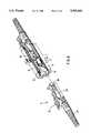
- FIG. 1is a plug connector dismantled down to its individual components with a sleeve portion according to the invention
- FIG. 2is the plug connector according to FIG. 1 in an assembled condition
- FIG. 3is a cross section through the plane I--I according to FIG. 2,
- FIG. 4is a cross section through the plane II--II according to FIG. 2,
- FIG. 5is a perspective representation of the inner sleeve portion with a view of the underside
- FIG. 6is a perspective representation of a plug connector with partly cutaway sleeve portion.
- FIG. 1shows the individual components of a typical plug connector having a receptacle 1 and a plug 4.
- the receptacle 1is in addition designed to accommodate two plugs 4 of the same type from both sides, each plug ferrule 3 penetrating into a socket 2 and thereby being centered in relation to the plug ferrule lying opposite.
- the sleeve portion 1has an outer receptacle 9 with a flange 13 by which the sleeve portion can be screwed, for example, onto a housing wall.
- the inner sleeve portion 8is inserted into the outer sleeve portion 9.
- both the inner and outer sleeve housingshave an approximately box shaped, rectangular cross section. Fixing of the inner sleeve housing in the outer sleeve housing ensues through snap-on attachable end frames 17 and 17', as can in particular be seen in FIG. 2.
- the inner sleeve housing 8has sprung locking catches 14, 14' on its upper side which serve to retain the plug in the inserted position.
- Guide grooves 15are arranged on the side walls of the inner sleeve housing 8 which serve to accept the plug in the correct orientation.
- An opening 16is provided on the underside of the inner sleeve housing 8 through which the socket 2, with the associated socket holder 12, 12', can be inserted.
- the socketis preferably floatingly mounted in the socket holder, both portions of which have flange type edge sections 25, 25' which are oriented towards each other.
- lateral guide grooves 26receive both the edge sections.
- a leaf spring 7, the ends 18, 18' of which engage on the protective flap 6, 6',is arranged beneath the socket holder.
- the middle section 19 of the leaf springis formed as a clasp in which both the edge sections 25, 25' of the socket holder engage. In this way, the position of the leaf spring 7 is fixed in the sleeve housing.
- each protective flaphas an approximately rectangular form and is equipped with lateral linkage lugs 10 which are held between the inner and outer sleeve housings. Apart from that, each protective flap has lateral limit stop lugs 11, which engage laterally in the guide grooves 15 and which limit the inclined position when the flaps are closed. This inclined position in relation to the optical axis also causes the light emission to be reflected away, and provide a high return loss.
- the guide groovesopen laterally in the direction of pivoting in such a way that each protective flap can assume a position parallel to the centre axis of the sleeve.
- the distance of the mounting position for the linkage lugs 10 from the sleeve openings 5, respectively 5'is so selected that the free ends of each protective flap lie, in their open position, just in front of a sleeve opening.
- the plug 4, with its plug ferrule 3,can basically have any desired construction.
- itcomprises in principle a rectangular plug housing 22 which is provided with lateral guide rails 23. These guide rails fit into the guide grooves 15 on the sleeve portion.
- the locking catches 14, and 14'can engage in a respective locking bar 20 on the upper portion of the plug housing.
- a releasing lever 21 arranged on the plug housingserves to raise the locking catch and thus to release the locking device again.
- a ferrule holder 24is stamped into the plug housing 22, said ferrule holder 24 being connected firmly with the optical fibre cable, and with the plug ferrule 3, which are not shown in any greater detail here.
- FIG. 2shows the plug connector in an assembled condition, a plug 4 having been inserted into the right side, the left side remaining free. Both ends 18, 18' of the leaf spring engage, freely moveable, on the protective flaps 6 and 6' If no plug is inserted into the sleeve portion, the sleeve opening 5, seen from the direction of insertion a, remains covered. A light ray emitted from the inserted plug 4 will thus be reflected away by the protective flap 6.
- the front portion of the plug ferrule 3will thus run up against the protective flap and will press it, countering the force of the leaf spring, downwards with a pivoting movement until it has been forced back completely beneath the plane of the plug housing 22. This position is visible on the right side of FIG. 2, or in FIG. 4.
- the locking catch 14will engage behind the locking bar 20.
- the releasing lever 21In order to withdraw the plug, first the releasing lever 21 must be activated.
- the protective flapwill in each case, under the tension force of the spring, move in the direction of the closed position, as the plug permits it, until the final closed position is reached.
- the mounting of the socket 2, as shown,is particularly advantageous, especially when combined with the leaf spring and with the protective flaps. This mounting could also possess advantages independent from the protective flaps.
- all other componentsare preferably manufactured from a plastic material.
- the plug ferrule and the socketcould be made from a hard metal, ceramic or, if transmission loss is of lesser significance, from a plastic material.
- FIG. 5an assembly sequence of a sleeve portion according to the invention is shown.
- An opening 16which extends practically along the entire length of the sleeve housing, is visible on the underside of the inner sleeve portion 8.
- the width of the openingapproximately corresponds to the width of both protective flaps 6, 6'.
- the linkage lugs 10 and the limit stop lugs 11 of the protective flapsare introduced via lateral grooves 27.
- the already inserted flange type edge sections 25, 25' of the sleeve holderengage, in their mounted condition, with the middle clasp section 19 of the leaf spring 7.
- the ends 18, 18' of the leaf springare bent down and move without fixed connection in the openings 30 on the protective flaps. After placing both the protective flaps 6, 6' into the inner sleeve portion 8, the leaf spring 7 is placed upon them and subsequently the entire unit is slid into the outer sleeve housing 9. This procedure permits relatively simple automation.
- FIG. 6a plug connector with a sleeve portion according to the invention is once again represented. Both the plugs 4 are likewise equipped with a protective flap 28, which automatically flaps up during insertion into the plug. Kinking protection is suggested with 29, which protects the area of transition between the optical fibre cable and the plug 4.
Landscapes
- Physics & Mathematics (AREA)
- General Physics & Mathematics (AREA)
- Optics & Photonics (AREA)
- Mechanical Coupling Of Light Guides (AREA)
Abstract
Description
The invention concerns a sleeve portion for an optical fibre plug connector. These types of sleeve portions are mainly used as adaptors or middle portions for attachment on a housing wall.
The purpose of these types of sleeve portions is to protect the sleeve opening from contamination or from mechanical influences. Also, the emission of light from the sleeve portion when the plug ferrule is withdrawn should be prevented. If this light is laser light, eye injuries could result as soon as the light ray falls on the unprotected retina. The emission of light from the sleeve portion could also be undesirable for other technical reasons.
In JP-A-57/142 607, a connection sleeve for a photo-electric transducer is described in which the entrance opening for the optical fibre is closed off by a spring tensioned cover. On insertion of the fibre, the cover is displaced to the side. With a plug connector described in "Research Disclosure" No. 275, of March 1987, page 124, the sleeve opening is covered by a flexible disk which is pressed into a hollow space when the plug ferrule is inserted.
A problem with the known sleeve portions is that the assembly and mounting of the protective flaps is accompanied by considerable difficulties. The protective flaps must, in fact, fulfil their functions within the smallest off spaces, and they have, of necessity, very small dimensions amounting to a few millimeters. Thus, assembly is relatively laborious.
In addition, there is the requirement that the protective flap be as a rule tensioned by a separate spring. Only in this way will it be ensured that the protective flap remains in the closed position when the plug ferrule is withdrawn.
It is therefore a purpose of the invention to create a sleeve portion of the type mentioned in the introduction, with which the protective flap, with the highest degree of operating security, can be assembled and disassembled in the simplest way. According to the invention, this purpose is fulfilled with a sleeve portion described below. Since the protective flap is held and mounted to be able to pivot between both sleeve housings, it can be assembled and disassembled in a particularly simple way. There is no requirement for a separate axle or similar, as, for example, is the case with JP-A-57/142 607. The protective flap remains connected with the sleeve portion regardless, and will not be lost, and with operating problems it is easily accessible or replaceable at all times. Operating security is considerably increased because the protective flap is mounted to be able to pivot and because it is held in the closed position under spring tension. By this means, the protective flap automatically pivots back into the closed position as soon as the plug ferrule is withdrawn from the sleeve.
At the same time, it is particularly advantageous if the protective flap is held in the closed position at an angle which is inclined in relation to the centre axis of the sleeve and if it is able to be pivoted into the open position in the direction towards the sleeve opening. Through the inclined position, the protective flap must only carry out a relatively small pivoting motion into the open position, and the insertion resistance for the plug will only be slightly raised.
The protective flap is preferably tensioned into the closed position by a leaf spring. The leaf spring can be easily accommodated in the sleeve portion, and the spring force is easily sufficient to place the protective flap under tension.
The protective flap can possess lateral linkage lugs for pivotable mounting in the mounting positions formed by both the sleeve housings. It would also be conceivable without problems to mount the protective flap in guide grooves or the like. The protective flap can furthermore possess lateral limit stop lugs for limiting of the position when closed. With that, with regard to the forces involved, a particularity favourable inclined position of the protective flap can be selected. The protective flap can be formed approximately as a rectangle, since this will considerably simplify its lateral guidance and mounting. It could, without further problems, also be circular or possess a rounded form.
It is particularly advantageous if the inner sleeve housing has at least one opening in the housing wall through which the protective flap is able to be slid for assembly and disassembly, this opening being able to be closed off by the outer sleeve housing. This opening permits placement of the sleeve flap in the correct place in the most direct way, without difficult manipulation or auxiliary tools being necessary. Assembly can thus be easily automated.
The sleeve portion can possess a sleeve in which the plug ferrule is able to be inserted from both sides, a protective flap being arranged in front of each sleeve opening. Through that, the sleeve portion according to the invention can be used in many ways, since in principle it is of no consequence which of the inserted plugs carries the optical fibre which emits light. With any desired combination, it is reliably ensured that the sleeve opening is covered when the plug ferrule is withdrawn.
In the case of a double sided sleeve portion, both the protective flaps will preferably be tensioned in the closed position by a common leaf spring which is arranged beneath the sleeve in the sleeve portion. The leaf spring can, with that, be fixed in its position by a sleeve holder which is able to be inserted into the sleeve portion, and indeed through an opening in the inner sleeve portion, in a similar way to the protective flap itself.
Further advantages and individual features arise from following description of an embodiment, and from the drawings, wherein:
FIG. 1 is a plug connector dismantled down to its individual components with a sleeve portion according to the invention,
FIG. 2 is the plug connector according to FIG. 1 in an assembled condition,
FIG. 3 is a cross section through the plane I--I according to FIG. 2,
FIG. 4 is a cross section through the plane II--II according to FIG. 2,
FIG. 5 is a perspective representation of the inner sleeve portion with a view of the underside, and
FIG. 6 is a perspective representation of a plug connector with partly cutaway sleeve portion.
FIG. 1 shows the individual components of a typical plug connector having areceptacle 1 and a plug 4. Thereceptacle 1 is in addition designed to accommodate two plugs 4 of the same type from both sides, eachplug ferrule 3 penetrating into asocket 2 and thereby being centered in relation to the plug ferrule lying opposite.
Thesleeve portion 1 has anouter receptacle 9 with aflange 13 by which the sleeve portion can be screwed, for example, onto a housing wall. Theinner sleeve portion 8 is inserted into theouter sleeve portion 9. As is made clear particularly in FIGS. 3 and 4, both the inner and outer sleeve housings have an approximately box shaped, rectangular cross section. Fixing of the inner sleeve housing in the outer sleeve housing ensues through snap-onattachable end frames 17 and 17', as can in particular be seen in FIG. 2.
Theinner sleeve housing 8 has sprunglocking catches 14, 14' on its upper side which serve to retain the plug in the inserted position.Guide grooves 15 are arranged on the side walls of theinner sleeve housing 8 which serve to accept the plug in the correct orientation. Anopening 16 is provided on the underside of the inner sleeve housing 8 through which thesocket 2, with the associatedsocket holder 12, 12', can be inserted.
The socket is preferably floatingly mounted in the socket holder, both portions of which have flangetype edge sections 25, 25' which are oriented towards each other. On the inner sleeve housing,lateral guide grooves 26 receive both the edge sections. A leaf spring 7, theends 18, 18' of which engage on theprotective flap 6, 6', is arranged beneath the socket holder. Themiddle section 19 of the leaf spring is formed as a clasp in which both theedge sections 25, 25' of the socket holder engage. In this way, the position of the leaf spring 7 is fixed in the sleeve housing.
The configuration of both theprotective flaps 6, 6' can be particularly seen in FIG. 3. Each protective flap has an approximately rectangular form and is equipped withlateral linkage lugs 10 which are held between the inner and outer sleeve housings. Apart from that, each protective flap has laterallimit stop lugs 11, which engage laterally in theguide grooves 15 and which limit the inclined position when the flaps are closed. This inclined position in relation to the optical axis also causes the light emission to be reflected away, and provide a high return loss. Now, the guide grooves open laterally in the direction of pivoting in such a way that each protective flap can assume a position parallel to the centre axis of the sleeve. The distance of the mounting position for the linkage lugs 10 from thesleeve openings 5, respectively 5' is so selected that the free ends of each protective flap lie, in their open position, just in front of a sleeve opening.
The plug 4, with itsplug ferrule 3, can basically have any desired construction. In the embodiment shown, it comprises in principle arectangular plug housing 22 which is provided with lateral guide rails 23. These guide rails fit into theguide grooves 15 on the sleeve portion. The locking catches 14, and 14' can engage in arespective locking bar 20 on the upper portion of the plug housing. A releasinglever 21 arranged on the plug housing serves to raise the locking catch and thus to release the locking device again. Aferrule holder 24 is stamped into theplug housing 22, saidferrule holder 24 being connected firmly with the optical fibre cable, and with theplug ferrule 3, which are not shown in any greater detail here.
FIG. 2 shows the plug connector in an assembled condition, a plug 4 having been inserted into the right side, the left side remaining free. Both ends 18, 18' of the leaf spring engage, freely moveable, on theprotective flaps 6 and 6' If no plug is inserted into the sleeve portion, thesleeve opening 5, seen from the direction of insertion a, remains covered. A light ray emitted from the inserted plug 4 will thus be reflected away by theprotective flap 6.
If now a plug 4 is inserted into the sleeve portion, the front portion of theplug ferrule 3 will thus run up against the protective flap and will press it, countering the force of the leaf spring, downwards with a pivoting movement until it has been forced back completely beneath the plane of theplug housing 22. This position is visible on the right side of FIG. 2, or in FIG. 4. As soon as the plug has reached its end position, the lockingcatch 14 will engage behind the lockingbar 20. In order to withdraw the plug, first the releasinglever 21 must be activated. The protective flap will in each case, under the tension force of the spring, move in the direction of the closed position, as the plug permits it, until the final closed position is reached.
The mounting of thesocket 2, as shown, is particularly advantageous, especially when combined with the leaf spring and with the protective flaps. This mounting could also possess advantages independent from the protective flaps. With the exception of thesocket 3 and theplug ferrule 2, all other components are preferably manufactured from a plastic material. The plug ferrule and the socket could be made from a hard metal, ceramic or, if transmission loss is of lesser significance, from a plastic material.
In FIG. 5, an assembly sequence of a sleeve portion according to the invention is shown. Anopening 16, which extends practically along the entire length of the sleeve housing, is visible on the underside of theinner sleeve portion 8. The width of the opening approximately corresponds to the width of bothprotective flaps 6, 6'. The linkage lugs 10 and the limit stop lugs 11 of the protective flaps are introduced vialateral grooves 27. Likewise visible here are the already inserted flangetype edge sections 25, 25' of the sleeve holder. These edge sections engage, in their mounted condition, with themiddle clasp section 19 of the leaf spring 7.
The ends 18, 18' of the leaf spring are bent down and move without fixed connection in theopenings 30 on the protective flaps. After placing both theprotective flaps 6, 6' into theinner sleeve portion 8, the leaf spring 7 is placed upon them and subsequently the entire unit is slid into theouter sleeve housing 9. This procedure permits relatively simple automation.
In FIG. 6, a plug connector with a sleeve portion according to the invention is once again represented. Both the plugs 4 are likewise equipped with aprotective flap 28, which automatically flaps up during insertion into the plug. Kinking protection is suggested with 29, which protects the area of transition between the optical fibre cable and the plug 4.
Inasmuch as the invention is subject to modifications and variations, the foregoing description and accompanying drawings should not be regarded as limiting the invention, which is defined by the following claims and various combinations thereof.
Claims (11)
1. In a fiber optical plug connector receptacle having at least one socket with an open end for receiving a ferrule of a plug which can be inserted into the receptacle, the receptacle having a protective flap movably mounted in front of the opening, said flap having a deployed position at least partially covering the socket opening and a stowed position in uncovering the opening, the improvement wherein the receptacle comprises an outer sleeve housing and an inner sleeve housing which is slid into the outer sleeve housing, and the protective flap is held between the sleeve housings and is mounted so that it can pivot between said positions.
2. The invention of claim 1, wherein the socket has two open ends so that a plug ferrule can be inserted into the socket from either end, and further comprising a protective flap arranged in front of each open end.
3. The invention of claim 2, wherein both said flaps are biased toward their respective deployed positions by a common leaf spring disposed beneath the socket in the receptacle.
4. The invention of claim 2, wherein the socket is mounted in a socket holder which can be slid into the inner sleeve housing, and the leaf spring is retained in position by the socket holder.
5. The invention of claim 4, wherein the socket holder has two components, having opposed lateral flanges, and the leaf spring has a middle section in which both flanges engages.
6. The invention of claim 1, wherein the protective flap has lateral linkage lugs arranged on a pivot axis, and the inner sleeve housing has means for receiving said lugs.
7. The invention of claim 6, wherein the protective flap has lateral limit stops for preventing the flap from moving past its closed position.
8. The invention of claim 7, wherein the protective flap is approximately rectangular.
9. The invention of claim 1, further comprising a leaf spring biasing said flap toward said deployed position.
10. The invention of claim 1, wherein the receptacle has a longitudinal axis, and the flap, in its deployed position, lies at an angle inclined with respect to said longitudinal axis, and can pivot toward its stowed position by moving towards the socket opening.
11. The invention of claim 1, wherein the inner sleeve housing has a wall with at least one aperture therein, and the flap can slide through the aperture for assembly and disassembly, and the aperture can be closed off by the outer housing.
Applications Claiming Priority (2)
| Application Number | Priority Date | Filing Date | Title |
|---|---|---|---|
| CH362192 | 1992-11-26 | ||
| CH3621/92 | 1992-11-26 |
Publications (1)
| Publication Number | Publication Date |
|---|---|
| US5363460Atrue US5363460A (en) | 1994-11-08 |
Family
ID=4259922
Family Applications (1)
| Application Number | Title | Priority Date | Filing Date |
|---|---|---|---|
| US08/155,765Expired - LifetimeUS5363460A (en) | 1992-11-26 | 1993-11-23 | Sleeve portion for an optical fibre plug connector |
Country Status (5)
| Country | Link |
|---|---|
| US (1) | US5363460A (en) |
| EP (1) | EP0599784B1 (en) |
| JP (1) | JP2989093B2 (en) |
| AU (1) | AU660859B2 (en) |
| DE (1) | DE59305330D1 (en) |
Cited By (71)
| Publication number | Priority date | Publication date | Assignee | Title |
|---|---|---|---|---|
| US5452391A (en)* | 1994-06-22 | 1995-09-19 | Xintec Corporation | Reusable optical fiber connector adapter with optical barrier |
| US5570445A (en)* | 1994-06-22 | 1996-10-29 | Xintec Corporation | Reusable optical fiber connector adapter with plurality of optical barriers for all fiber delivery laser sources |
| EP0788002A1 (en) | 1996-02-01 | 1997-08-06 | Molex Incorporated | Fiber optic connector receptacle with protective shutter |
| US5675682A (en)* | 1995-02-21 | 1997-10-07 | Diamond Sa | Plug arrangement comprising at least two optical plugs |
| US5708745A (en)* | 1994-10-20 | 1998-01-13 | Fujitsu Limited | Device for preventing laser beam leakage |
| US5802229A (en)* | 1995-10-31 | 1998-09-01 | Indigo, Medical, Inc. | Fiber optic radiation transmisson system connector for an optical fiber and methods of usine same |
| US5845036A (en)* | 1996-08-08 | 1998-12-01 | Diamond Sa | Plug portion for an optical fiber connector |
| US5883995A (en)* | 1997-05-20 | 1999-03-16 | Adc Telecommunications, Inc. | Fiber connector and adapter |
| US5887098A (en)* | 1997-02-27 | 1999-03-23 | Molex Incorporated | Fiber optic adapter with protective shield |
| US5909526A (en)* | 1998-04-08 | 1999-06-01 | Molex Incorporated | Fiber optic connector assembly |
| US5915058A (en)* | 1998-01-05 | 1999-06-22 | Molex Incorporated | Fiber optic connector assembly |
| WO1999040466A1 (en)* | 1998-02-05 | 1999-08-12 | Alcoa Fujikura Ltd. | Fiber optic adapter shutter door assembly |
| US5940560A (en)* | 1996-10-28 | 1999-08-17 | Diamond Sa | Optical connection plug |
| US5956444A (en)* | 1997-02-13 | 1999-09-21 | Amphenol Corporation | Radiation absorbing shield for fiber optic systems |
| EP0949522A3 (en)* | 1998-04-08 | 1999-12-01 | Molex Incorporated | Fiber optic connector receptacle assembly |
| US6004043A (en)* | 1997-12-19 | 1999-12-21 | The Whitaker Corporation | Shuttered connector receptacle |
| US6081647A (en)* | 1998-01-05 | 2000-06-27 | Molex Incorporated | Fiber optic connector receptacle |
| US6108482A (en)* | 1998-01-14 | 2000-08-22 | Molex Incorporated | Fiber optic connector receptacle |
| GB2348512A (en)* | 1999-03-17 | 2000-10-04 | Krone Ag | Connector with pivotal shutter for signal carrying line |
| US6130977A (en)* | 1998-07-17 | 2000-10-10 | Siecor Operations, Llc | Fiber optic connector sleeve having positioning ribs |
| US6142676A (en)* | 1997-05-20 | 2000-11-07 | Adc Telecommunications, Inc. | Fiber connector and adaptor |
| US6154597A (en)* | 1998-01-05 | 2000-11-28 | Molex Incorporated | Fiber optic termination system including a fiber optic connector assembly and method of fabricating same |
| US6168318B1 (en)* | 1997-06-27 | 2001-01-02 | Ando Electric Co., Ltd. | Optical fiber positioning device and optical connector provided with this device |
| US6186670B1 (en)* | 1998-06-02 | 2001-02-13 | Pirelli Cable Corporation | Optical fiber connector module |
| US6188825B1 (en) | 1999-04-15 | 2001-02-13 | Lucent Technologies, Inc. | Dust cover for protecting optical fiber sleeve housing |
| EP1122565A1 (en)* | 2000-02-04 | 2001-08-08 | Molex Incorporated | Fiber optic connector receptacle |
| US6302592B1 (en)* | 1998-07-27 | 2001-10-16 | Huber & Suhner Ag | Connector for optical waveguides |
| RU2179733C2 (en)* | 1995-12-22 | 2002-02-20 | Миннесота Майнинг Энд Мэнюфекчуринг Компани | Socket with electrooptical device |
| US6454464B1 (en) | 1998-12-28 | 2002-09-24 | Computer Crafts, Inc. | Fiber optic connectors and transceiver test devices |
| US6464408B1 (en) | 1998-12-28 | 2002-10-15 | Computer Crafts, Inc. | Fiber optic connectors |
| US6547450B2 (en) | 2001-06-27 | 2003-04-15 | Fitel Usa Corp. | Quick-release dust cap for an optical plug |
| US6595696B1 (en) | 2001-03-14 | 2003-07-22 | Amphenol Corporation | Internal shutter for optical adapters |
| US6685362B2 (en) | 2000-03-24 | 2004-02-03 | Tyco Electronics Corporation | Shielded adapter assembly |
| US6688780B2 (en) | 2002-02-07 | 2004-02-10 | Amphenol Corporation | Cantilevered shutter for optical adapter |
| US20040052473A1 (en)* | 2002-09-03 | 2004-03-18 | The Furukawa Electric Co., Ltd. | Optical fiber connector part |
| EP1413906A1 (en)* | 2002-10-24 | 2004-04-28 | Japan Aviation Electronics Industry, Limited | Fiber optic connection adapter with shutter |
| US6758601B2 (en) | 2001-09-28 | 2004-07-06 | Adc Telecommunications, In. | Fiberoptic connector and methods |
| US6769814B2 (en) | 2001-08-31 | 2004-08-03 | Teradyne, Inc. | Waferized fiber optic connector |
| US20040179787A1 (en)* | 2003-03-10 | 2004-09-16 | Edward Glazowski | Dual shutter fiber optic connector |
| US20040223701A1 (en)* | 2003-01-27 | 2004-11-11 | Fujikura Ltd. | Optical connector with shutter, shutter unit, and inner piece |
| US20050100284A1 (en)* | 2003-11-06 | 2005-05-12 | Hu Lun S. | Optical fiber connector having stopping means |
| US20050141817A1 (en)* | 2003-12-24 | 2005-06-30 | Akihiko Yazaki | Optical connector, optical fiber with connector, optical fiber connecting device, and optical fiber connection method |
| US20050147358A1 (en)* | 2002-05-14 | 2005-07-07 | Patrick Zaina | Optical connector |
| US20080085082A1 (en)* | 2003-10-28 | 2008-04-10 | Michael Theis | Fiber-Optical Plug As Well As A Single And Double Coupler For Receiving Such A Plug |
| US20080090433A1 (en)* | 2006-10-11 | 2008-04-17 | Adam Murano | Secure fiber optic network keyed connector assembly |
| US7419309B2 (en) | 2004-03-17 | 2008-09-02 | Adc Gmbh | Optical fiber plug connector |
| US20080247710A1 (en)* | 2004-07-16 | 2008-10-09 | Tomoyasu Oike | Optical Connector and Optical Fiber Connecting System |
| US20080304795A1 (en)* | 2004-07-16 | 2008-12-11 | Tomayasu Oike | Optical Connector and Optical Fiber Connecting System |
| US7470068B2 (en) | 2002-05-03 | 2008-12-30 | Adc Gmbh | Coupling for optical-fiber connectors |
| US7540667B2 (en) | 2007-08-01 | 2009-06-02 | Ortronics, Inc. | Positional differentiating connector assembly |
| US20100054665A1 (en)* | 2008-08-29 | 2010-03-04 | Jones Ashley W | Fiber optic adapters with integrated shutter |
| US20100202736A1 (en)* | 2009-02-10 | 2010-08-12 | Amphenol Corporation | High density front panel optical interconnect |
| US20140024235A1 (en)* | 2012-07-20 | 2014-01-23 | Acist Medical Systems, Inc. | Connector cover for protecting a connection from contaminants |
| US20140065859A1 (en)* | 2012-09-05 | 2014-03-06 | Hyundai Motor Company | Battery management system connector for vehicle |
| US20140205239A1 (en)* | 2013-01-21 | 2014-07-24 | Sanwa Denki Kogyo Co., Ltd. | Interconnecting adapter for lc type optical connectors |
| WO2015047380A1 (en)* | 2013-09-30 | 2015-04-02 | Hewlett-Packard Development Company, Lp | Optical blind-mate connector and adapter |
| US20150131085A1 (en)* | 2013-11-11 | 2015-05-14 | Bi Incorporated | Systems and Methods for Reducing False Negative Tamper Detection |
| US9122020B2 (en) | 2012-06-06 | 2015-09-01 | Tyco Electronics Corporation | Connector assembly having a slidable connector |
| US9196997B2 (en) | 2011-11-10 | 2015-11-24 | Panduit Corp. | Shuttered LC adapter |
| US20160216456A1 (en)* | 2013-09-30 | 2016-07-28 | Hewlett Packard Enterprise Development Lp | Optical blind-mate connector and adapter |
| US9448367B2 (en)* | 2012-12-10 | 2016-09-20 | Applied Optoelectronics, Inc. | Multi-channel optical transceiver module including dual fiber type direct link adapter for optically coupling optical subassemblies in the transceiver module |
| US9494746B2 (en) | 2011-11-10 | 2016-11-15 | Panduit Corp. | Shuttered LC adapter |
| US9523822B2 (en)* | 2013-02-06 | 2016-12-20 | Xyratex Technology Limited | Optical connector |
| WO2017081298A1 (en)* | 2015-11-13 | 2017-05-18 | CommScope Connectivity Belgium BVBA | Shutter system for a fiber optic adapter |
| US9874702B2 (en)* | 2014-10-29 | 2018-01-23 | Hewlett Packard Enterprise Development Lp | Optical connector assembly apparatus |
| US20180358764A1 (en)* | 2015-12-08 | 2018-12-13 | Panduit Corp. | RJ45 Shuttered Jacks and Related Communication Systems |
| US10416392B2 (en)* | 2018-01-09 | 2019-09-17 | Advanced-Connectek Inc. | Optical adapter |
| US10444441B1 (en)* | 2018-08-10 | 2019-10-15 | Senko Advanced Components, Inc. | Pivotable housing for a fiber optic connector |
| US11307360B2 (en)* | 2018-01-17 | 2022-04-19 | Us Conec, Ltd. | Dual interlocking shutter system for a fiber optic connector and adapter |
| CN114447683A (en)* | 2022-01-19 | 2022-05-06 | 中航光电科技股份有限公司 | A push-pull plug with double protection device |
| US12265264B2 (en) | 2019-07-26 | 2025-04-01 | Commscope Technologies Llc | Fiber optic adapters convertible between different polarity types |
Families Citing this family (5)
| Publication number | Priority date | Publication date | Assignee | Title |
|---|---|---|---|---|
| DE29610409U1 (en)* | 1996-06-13 | 1996-09-05 | Siemens AG, 80333 München | Electrical connector |
| JP4499944B2 (en)* | 2001-03-12 | 2010-07-14 | 三和電気工業株式会社 | Optical connector housing |
| JP3753688B2 (en) | 2002-10-04 | 2006-03-08 | 日本航空電子工業株式会社 | Optical connector evening |
| KR101424848B1 (en)* | 2007-06-01 | 2014-08-01 | 쿠퍼 테크놀로지스 컴파니 | Jacket sleeve with gripable tabs for cable connector |
| CH702944A2 (en) | 2010-04-13 | 2011-10-14 | Huber+Suhner Ag | Optical connector. |
Citations (5)
| Publication number | Priority date | Publication date | Assignee | Title |
|---|---|---|---|---|
| US4645295A (en)* | 1980-02-04 | 1987-02-24 | Allied Corporation | Fiber optic connector |
| US4915472A (en)* | 1988-12-28 | 1990-04-10 | American Telephone And Telegraph Company, At&T Bell Laboratories | Optical fiber terminal plug connectors |
| US5212752A (en)* | 1992-05-27 | 1993-05-18 | At&T Bell Laboratories | Optical fiber ferrule connector having enhanced provisions for tuning |
| US5263106A (en)* | 1992-06-16 | 1993-11-16 | Siecor Corporation | Fiber optic attenuator for use with ferrules |
| US5265183A (en)* | 1992-07-02 | 1993-11-23 | Molex Incorporated | Fiber optic connector and tool for assembling same |
Family Cites Families (4)
| Publication number | Priority date | Publication date | Assignee | Title |
|---|---|---|---|---|
| JPS56107206A (en)* | 1980-01-31 | 1981-08-26 | Fujitsu Ltd | Preventing mechanism for laser hazard |
| JPS57142607A (en)* | 1981-02-27 | 1982-09-03 | Yamatake Honeywell Co Ltd | Connector for optical fiber |
| JPS63118707A (en)* | 1986-11-07 | 1988-05-23 | Hitachi Ltd | plug-in optical connector |
| US5263103A (en)* | 1992-11-16 | 1993-11-16 | At&T Bell Laboratories | Apparatus comprising a low reflection optical fiber termination |
- 1993
- 1993-11-11AUAU50638/93Apatent/AU660859B2/ennot_activeExpired
- 1993-11-15DEDE59305330Tpatent/DE59305330D1/ennot_activeExpired - Lifetime
- 1993-11-15EPEP93810790Apatent/EP0599784B1/ennot_activeExpired - Lifetime
- 1993-11-23USUS08/155,765patent/US5363460A/ennot_activeExpired - Lifetime
- 1993-11-25JPJP5295653Apatent/JP2989093B2/ennot_activeExpired - Lifetime
Patent Citations (5)
| Publication number | Priority date | Publication date | Assignee | Title |
|---|---|---|---|---|
| US4645295A (en)* | 1980-02-04 | 1987-02-24 | Allied Corporation | Fiber optic connector |
| US4915472A (en)* | 1988-12-28 | 1990-04-10 | American Telephone And Telegraph Company, At&T Bell Laboratories | Optical fiber terminal plug connectors |
| US5212752A (en)* | 1992-05-27 | 1993-05-18 | At&T Bell Laboratories | Optical fiber ferrule connector having enhanced provisions for tuning |
| US5263106A (en)* | 1992-06-16 | 1993-11-16 | Siecor Corporation | Fiber optic attenuator for use with ferrules |
| US5265183A (en)* | 1992-07-02 | 1993-11-23 | Molex Incorporated | Fiber optic connector and tool for assembling same |
Non-Patent Citations (3)
| Title |
|---|
| 2244 Research Disclosure (1987) Mar., No. 275, New York, New York, USA Van Goethem.* |
| Vol. 6, No. 245 (P 159) 1123 Dec. 3, 1982, Connector for Optical Fiber, Japan.* |
| Vol. 6, No. 245 (P-159) [1123] Dec. 3, 1982, Connector for Optical Fiber, Japan. |
Cited By (137)
| Publication number | Priority date | Publication date | Assignee | Title |
|---|---|---|---|---|
| US5570445A (en)* | 1994-06-22 | 1996-10-29 | Xintec Corporation | Reusable optical fiber connector adapter with plurality of optical barriers for all fiber delivery laser sources |
| US5452391A (en)* | 1994-06-22 | 1995-09-19 | Xintec Corporation | Reusable optical fiber connector adapter with optical barrier |
| US5708745A (en)* | 1994-10-20 | 1998-01-13 | Fujitsu Limited | Device for preventing laser beam leakage |
| US5675682A (en)* | 1995-02-21 | 1997-10-07 | Diamond Sa | Plug arrangement comprising at least two optical plugs |
| US5848209A (en)* | 1995-10-31 | 1998-12-08 | Indigo Medical Inc. | Connection apparatus with optical fiber coding and detection means or with radiation emitter |
| US5802229A (en)* | 1995-10-31 | 1998-09-01 | Indigo, Medical, Inc. | Fiber optic radiation transmisson system connector for an optical fiber and methods of usine same |
| US5875275A (en)* | 1995-10-31 | 1999-02-23 | Indigo Medical, Inc. | Methods of connecting an optical fiber and methods of providing radiation from an optical fiber |
| RU2179733C2 (en)* | 1995-12-22 | 2002-02-20 | Миннесота Майнинг Энд Мэнюфекчуринг Компани | Socket with electrooptical device |
| EP0788002A1 (en) | 1996-02-01 | 1997-08-06 | Molex Incorporated | Fiber optic connector receptacle with protective shutter |
| US5845036A (en)* | 1996-08-08 | 1998-12-01 | Diamond Sa | Plug portion for an optical fiber connector |
| US5940560A (en)* | 1996-10-28 | 1999-08-17 | Diamond Sa | Optical connection plug |
| AU728301B2 (en)* | 1996-10-28 | 2001-01-04 | Diamond S.A. | Plug for an optical plug connector |
| US5956444A (en)* | 1997-02-13 | 1999-09-21 | Amphenol Corporation | Radiation absorbing shield for fiber optic systems |
| US5887098A (en)* | 1997-02-27 | 1999-03-23 | Molex Incorporated | Fiber optic adapter with protective shield |
| US7384201B2 (en)* | 1997-05-20 | 2008-06-10 | Adc Telecommunications, Inc. | Fiber connector and adapter |
| US6142676A (en)* | 1997-05-20 | 2000-11-07 | Adc Telecommunications, Inc. | Fiber connector and adaptor |
| US5984531A (en)* | 1997-05-20 | 1999-11-16 | Adc Telecommunications, Inc. | Fiber connector and adapter |
| US7654749B2 (en) | 1997-05-20 | 2010-02-02 | Adc Telecommunications, Inc. | Fiber connector and adapter |
| US6471416B2 (en)* | 1997-05-20 | 2002-10-29 | Adc Telecommunications, Inc. | Fiber connector and adapter |
| US6076973A (en)* | 1997-05-20 | 2000-06-20 | Adc Telecommunications, Inc. | Fiber connector and adapter |
| US20100195958A1 (en)* | 1997-05-20 | 2010-08-05 | Adc Telecommunications, Inc. | Fiber connector and adapter |
| US20080279507A1 (en)* | 1997-05-20 | 2008-11-13 | Adc Telecommunications, Inc. | Fiber connector and adapter |
| US7874738B2 (en) | 1997-05-20 | 2011-01-25 | Adc Telecommunications, Inc. | Fiber connector and adapter |
| US20070253666A1 (en)* | 1997-05-20 | 2007-11-01 | Adc Telecommunications, Inc. | Fiber connector and adapter |
| US7246950B2 (en) | 1997-05-20 | 2007-07-24 | Adc Telecommunications, Inc. | Fiber connector and adapter |
| US20090199398A1 (en)* | 1997-05-20 | 2009-08-13 | Adc Telecommunications, Inc | Fiber connector and adapter |
| US20070086706A1 (en)* | 1997-05-20 | 2007-04-19 | Adc Telecommunications, Inc. | Fiber connector and adapter |
| US9383524B2 (en) | 1997-05-20 | 2016-07-05 | Commscope Technologies Llc | Fiber connector and adapter |
| US7503702B2 (en) | 1997-05-20 | 2009-03-17 | Adc Telecommunications, Inc. | Fiber connector and adapter |
| US8186890B2 (en) | 1997-05-20 | 2012-05-29 | Adc Telecommunications, Inc. | Fiber connector and adapter |
| US7118288B2 (en) | 1997-05-20 | 2006-10-10 | Adc Telecommunications, Inc. | Fiber connector and adapter |
| US20050169583A1 (en)* | 1997-05-20 | 2005-08-04 | Adc Telecommunications, Inc. | Fiber connector and adapter |
| US8870466B2 (en) | 1997-05-20 | 2014-10-28 | Adc Telecommunications, Inc. | Fiber connector and adapter |
| US6296398B1 (en) | 1997-05-20 | 2001-10-02 | Adc Telecommunications, Inc. | Fiber connector and adapter |
| US6910807B2 (en)* | 1997-05-20 | 2005-06-28 | Adc Telecommunications, Inc. | Fiber connector and adapter |
| US5883995A (en)* | 1997-05-20 | 1999-03-16 | Adc Telecommunications, Inc. | Fiber connector and adapter |
| US6168318B1 (en)* | 1997-06-27 | 2001-01-02 | Ando Electric Co., Ltd. | Optical fiber positioning device and optical connector provided with this device |
| US6004043A (en)* | 1997-12-19 | 1999-12-21 | The Whitaker Corporation | Shuttered connector receptacle |
| US6081647A (en)* | 1998-01-05 | 2000-06-27 | Molex Incorporated | Fiber optic connector receptacle |
| US6154597A (en)* | 1998-01-05 | 2000-11-28 | Molex Incorporated | Fiber optic termination system including a fiber optic connector assembly and method of fabricating same |
| US5915058A (en)* | 1998-01-05 | 1999-06-22 | Molex Incorporated | Fiber optic connector assembly |
| US6108482A (en)* | 1998-01-14 | 2000-08-22 | Molex Incorporated | Fiber optic connector receptacle |
| WO1999040466A1 (en)* | 1998-02-05 | 1999-08-12 | Alcoa Fujikura Ltd. | Fiber optic adapter shutter door assembly |
| EP0949522A3 (en)* | 1998-04-08 | 1999-12-01 | Molex Incorporated | Fiber optic connector receptacle assembly |
| US6079881A (en)* | 1998-04-08 | 2000-06-27 | Molex Incorporated | Fiber optic connector receptacle assembly |
| US5909526A (en)* | 1998-04-08 | 1999-06-01 | Molex Incorporated | Fiber optic connector assembly |
| SG81264A1 (en)* | 1998-04-08 | 2001-06-19 | Molex Inc | Fiber optic connector receptacle assembly |
| US6186670B1 (en)* | 1998-06-02 | 2001-02-13 | Pirelli Cable Corporation | Optical fiber connector module |
| US6130977A (en)* | 1998-07-17 | 2000-10-10 | Siecor Operations, Llc | Fiber optic connector sleeve having positioning ribs |
| US6302592B1 (en)* | 1998-07-27 | 2001-10-16 | Huber & Suhner Ag | Connector for optical waveguides |
| US6554487B2 (en) | 1998-12-28 | 2003-04-29 | Computer Crafts, Inc. | Fiber optic connectors |
| US6464408B1 (en) | 1998-12-28 | 2002-10-15 | Computer Crafts, Inc. | Fiber optic connectors |
| US6454464B1 (en) | 1998-12-28 | 2002-09-24 | Computer Crafts, Inc. | Fiber optic connectors and transceiver test devices |
| GB2348512A (en)* | 1999-03-17 | 2000-10-04 | Krone Ag | Connector with pivotal shutter for signal carrying line |
| US6188825B1 (en) | 1999-04-15 | 2001-02-13 | Lucent Technologies, Inc. | Dust cover for protecting optical fiber sleeve housing |
| US6471412B1 (en) | 2000-02-04 | 2002-10-29 | Molex Incorporated | Fiber optic connector receptacle |
| EP1122565A1 (en)* | 2000-02-04 | 2001-08-08 | Molex Incorporated | Fiber optic connector receptacle |
| US6685362B2 (en) | 2000-03-24 | 2004-02-03 | Tyco Electronics Corporation | Shielded adapter assembly |
| US6595696B1 (en) | 2001-03-14 | 2003-07-22 | Amphenol Corporation | Internal shutter for optical adapters |
| US6547450B2 (en) | 2001-06-27 | 2003-04-15 | Fitel Usa Corp. | Quick-release dust cap for an optical plug |
| US6769814B2 (en) | 2001-08-31 | 2004-08-03 | Teradyne, Inc. | Waferized fiber optic connector |
| US6758601B2 (en) | 2001-09-28 | 2004-07-06 | Adc Telecommunications, In. | Fiberoptic connector and methods |
| US7226214B2 (en) | 2001-09-28 | 2007-06-05 | Adc Telecommunications, Inc. | Fiberoptic connector and methods |
| US7510334B2 (en) | 2001-09-28 | 2009-03-31 | Adc Telecommunications, Inc. | Fiberoptic connector and methods |
| US20040234207A1 (en)* | 2001-09-28 | 2004-11-25 | Adc Telecommunications, Inc. | Fiberoptic connector and methods |
| US20080131059A1 (en)* | 2001-09-28 | 2008-06-05 | Adc Telecommunications, Inc. | Fiberoptic connector and methods |
| US6688780B2 (en) | 2002-02-07 | 2004-02-10 | Amphenol Corporation | Cantilevered shutter for optical adapter |
| US20090136183A1 (en)* | 2002-05-03 | 2009-05-28 | Adc Gmbh | Coupling for optical-fiber connectors |
| US7470068B2 (en) | 2002-05-03 | 2008-12-30 | Adc Gmbh | Coupling for optical-fiber connectors |
| US7611291B2 (en) | 2002-05-03 | 2009-11-03 | Adc Gmbh | Coupling for optical-fiber connectors |
| US7283718B2 (en)* | 2002-05-14 | 2007-10-16 | Huber+Suhner Ag | Optical connector with protective cover and leaf spring |
| US20050147358A1 (en)* | 2002-05-14 | 2005-07-07 | Patrick Zaina | Optical connector |
| US20040052473A1 (en)* | 2002-09-03 | 2004-03-18 | The Furukawa Electric Co., Ltd. | Optical fiber connector part |
| US20040081419A1 (en)* | 2002-10-24 | 2004-04-29 | Jun Takeda | Optical fiber splicing instrument with shutter |
| EP1413906A1 (en)* | 2002-10-24 | 2004-04-28 | Japan Aviation Electronics Industry, Limited | Fiber optic connection adapter with shutter |
| US7144163B2 (en)* | 2003-01-27 | 2006-12-05 | Fujikura Ltd. | Optical connector with shutter, shutter unit, and inner piece |
| US20040223701A1 (en)* | 2003-01-27 | 2004-11-11 | Fujikura Ltd. | Optical connector with shutter, shutter unit, and inner piece |
| US20040179787A1 (en)* | 2003-03-10 | 2004-09-16 | Edward Glazowski | Dual shutter fiber optic connector |
| US20080085082A1 (en)* | 2003-10-28 | 2008-04-10 | Michael Theis | Fiber-Optical Plug As Well As A Single And Double Coupler For Receiving Such A Plug |
| US7488115B2 (en) | 2003-10-28 | 2009-02-10 | Euromicron Werkzeuge Gmbh | Fiber-optical plug as well as a single and double coupler for receiving such a plug |
| US20050100284A1 (en)* | 2003-11-06 | 2005-05-12 | Hu Lun S. | Optical fiber connector having stopping means |
| US7186034B2 (en)* | 2003-11-06 | 2007-03-06 | Hon Hai Precision Ind. Co., Ltd. | Optical fiber connector having stopping means |
| US7331718B2 (en)* | 2003-12-24 | 2008-02-19 | 3M Innovative Properties Company | Optical connector, optical fiber with connector, optical fiber connecting device, and optical fiber connection method |
| US20090080839A1 (en)* | 2003-12-24 | 2009-03-26 | 3M Innovative Properties Company | Optical connector, optical fiber with connector, optical fiber connecting device, and optical fiber connection method |
| US20050141817A1 (en)* | 2003-12-24 | 2005-06-30 | Akihiko Yazaki | Optical connector, optical fiber with connector, optical fiber connecting device, and optical fiber connection method |
| US20080292246A1 (en)* | 2003-12-24 | 2008-11-27 | 3M Innovative Properties Company | Optical connector, optical fiber with connector, optical fiber connecting device, and optical fiber connection method |
| US7942589B2 (en) | 2003-12-24 | 2011-05-17 | 3M Innovative Properties Company | Optical connector, optical fiber with connector, optical fiber connecting device, and optical fiber connection method |
| US7419309B2 (en) | 2004-03-17 | 2008-09-02 | Adc Gmbh | Optical fiber plug connector |
| US7690848B2 (en) | 2004-03-17 | 2010-04-06 | Adc Gmbh | Optical fiber plug connector |
| US20080317413A1 (en)* | 2004-03-17 | 2008-12-25 | Adc Gmbh | Optical fiber plug connector |
| US20080247710A1 (en)* | 2004-07-16 | 2008-10-09 | Tomoyasu Oike | Optical Connector and Optical Fiber Connecting System |
| US7637673B2 (en) | 2004-07-16 | 2009-12-29 | 3M Innovative Properties Company | Optical connector and optical fiber connecting system |
| US7556438B2 (en) | 2004-07-16 | 2009-07-07 | 3M Innovative Properties Company | Optical connector and optical fiber connecting system |
| US20080304795A1 (en)* | 2004-07-16 | 2008-12-11 | Tomayasu Oike | Optical Connector and Optical Fiber Connecting System |
| US7390203B2 (en)* | 2006-10-11 | 2008-06-24 | Ortronics, Inc. | Secure fiber optic network keyed connector assembly |
| US7534115B2 (en) | 2006-10-11 | 2009-05-19 | Ortronics, Inc. | Secure fiber optic network keyed connector assembly |
| US20080090433A1 (en)* | 2006-10-11 | 2008-04-17 | Adam Murano | Secure fiber optic network keyed connector assembly |
| US7850370B2 (en) | 2007-08-01 | 2010-12-14 | Ortronics, Inc. | Positional differentiating connector assembly |
| US7540667B2 (en) | 2007-08-01 | 2009-06-02 | Ortronics, Inc. | Positional differentiating connector assembly |
| US7785018B2 (en) | 2008-08-29 | 2010-08-31 | Corning Cable Systems Llc | Fiber optic adapters with integrated shutter |
| US20100054665A1 (en)* | 2008-08-29 | 2010-03-04 | Jones Ashley W | Fiber optic adapters with integrated shutter |
| US8348516B2 (en)* | 2009-02-10 | 2013-01-08 | Amphenol Corporation | High density front panel optical interconnect |
| US20100202736A1 (en)* | 2009-02-10 | 2010-08-12 | Amphenol Corporation | High density front panel optical interconnect |
| US9709754B2 (en) | 2011-11-10 | 2017-07-18 | Panduit Corp. | Shuttered LC adapter |
| US10012799B2 (en) | 2011-11-10 | 2018-07-03 | Panduit Corp. | Shuttered LC adapter |
| US9196997B2 (en) | 2011-11-10 | 2015-11-24 | Panduit Corp. | Shuttered LC adapter |
| US9494746B2 (en) | 2011-11-10 | 2016-11-15 | Panduit Corp. | Shuttered LC adapter |
| US9122020B2 (en) | 2012-06-06 | 2015-09-01 | Tyco Electronics Corporation | Connector assembly having a slidable connector |
| US8968014B2 (en)* | 2012-07-20 | 2015-03-03 | Acist Medical Systems, Inc. | Connector cover for protecting a connection from contaminants |
| US20140024235A1 (en)* | 2012-07-20 | 2014-01-23 | Acist Medical Systems, Inc. | Connector cover for protecting a connection from contaminants |
| US8961203B2 (en)* | 2012-09-05 | 2015-02-24 | Hyundai Motor Company | Battery management system connector for vehicle |
| US20140065859A1 (en)* | 2012-09-05 | 2014-03-06 | Hyundai Motor Company | Battery management system connector for vehicle |
| US9448367B2 (en)* | 2012-12-10 | 2016-09-20 | Applied Optoelectronics, Inc. | Multi-channel optical transceiver module including dual fiber type direct link adapter for optically coupling optical subassemblies in the transceiver module |
| US9128255B2 (en)* | 2013-01-21 | 2015-09-08 | Sanwa Denki Kogyo Co., Ltd. | Interconnecting adapter for LC type optical connectors |
| US20140205239A1 (en)* | 2013-01-21 | 2014-07-24 | Sanwa Denki Kogyo Co., Ltd. | Interconnecting adapter for lc type optical connectors |
| US10107970B2 (en) | 2013-02-06 | 2018-10-23 | Xyratex Technology Limited | Optical connector |
| US9523822B2 (en)* | 2013-02-06 | 2016-12-20 | Xyratex Technology Limited | Optical connector |
| WO2015047380A1 (en)* | 2013-09-30 | 2015-04-02 | Hewlett-Packard Development Company, Lp | Optical blind-mate connector and adapter |
| US9927584B2 (en)* | 2013-09-30 | 2018-03-27 | Hewlett Packard Enterprise Development Lp | Optical blind-mate connector and adapter |
| US9581767B2 (en)* | 2013-09-30 | 2017-02-28 | Hewlett Packard Enterprise Development Lp | Optical blind-mate connector and adapter |
| CN105593733A (en)* | 2013-09-30 | 2016-05-18 | 慧与发展有限责任合伙企业 | Optical blind-mate connector and adapter |
| US20160216456A1 (en)* | 2013-09-30 | 2016-07-28 | Hewlett Packard Enterprise Development Lp | Optical blind-mate connector and adapter |
| US20160195681A1 (en)* | 2013-09-30 | 2016-07-07 | Hewlett Packard Enterprise Development Lp | Optical blind-mate connector and adapter |
| CN105593733B (en)* | 2013-09-30 | 2017-09-22 | 慧与发展有限责任合伙企业 | Light blindmate connector and adapter |
| US9798092B2 (en)* | 2013-09-30 | 2017-10-24 | Hewlett Packard Enterprise Development Lp | Optical blind-mate connector and adapter |
| US9629420B2 (en)* | 2013-11-11 | 2017-04-25 | Bi Incorporated | Systems and methods for reducing false negative tamper detection |
| US20150131085A1 (en)* | 2013-11-11 | 2015-05-14 | Bi Incorporated | Systems and Methods for Reducing False Negative Tamper Detection |
| US9874702B2 (en)* | 2014-10-29 | 2018-01-23 | Hewlett Packard Enterprise Development Lp | Optical connector assembly apparatus |
| WO2017081298A1 (en)* | 2015-11-13 | 2017-05-18 | CommScope Connectivity Belgium BVBA | Shutter system for a fiber optic adapter |
| US20180358764A1 (en)* | 2015-12-08 | 2018-12-13 | Panduit Corp. | RJ45 Shuttered Jacks and Related Communication Systems |
| US11817659B2 (en)* | 2015-12-08 | 2023-11-14 | Panduit Corp. | RJ45 shuttered jacks and related communication systems |
| US10416392B2 (en)* | 2018-01-09 | 2019-09-17 | Advanced-Connectek Inc. | Optical adapter |
| US11307360B2 (en)* | 2018-01-17 | 2022-04-19 | Us Conec, Ltd. | Dual interlocking shutter system for a fiber optic connector and adapter |
| US10444441B1 (en)* | 2018-08-10 | 2019-10-15 | Senko Advanced Components, Inc. | Pivotable housing for a fiber optic connector |
| US12265264B2 (en) | 2019-07-26 | 2025-04-01 | Commscope Technologies Llc | Fiber optic adapters convertible between different polarity types |
| CN114447683A (en)* | 2022-01-19 | 2022-05-06 | 中航光电科技股份有限公司 | A push-pull plug with double protection device |
| CN114447683B (en)* | 2022-01-19 | 2024-03-19 | 中航光电科技股份有限公司 | A push-pull plug with double-layer protection device |
Also Published As
| Publication number | Publication date |
|---|---|
| JPH06201953A (en) | 1994-07-22 |
| EP0599784A1 (en) | 1994-06-01 |
| AU660859B2 (en) | 1995-07-06 |
| EP0599784B1 (en) | 1997-01-29 |
| JP2989093B2 (en) | 1999-12-13 |
| AU5063893A (en) | 1994-06-09 |
| DE59305330D1 (en) | 1997-03-13 |
Similar Documents
| Publication | Publication Date | Title |
|---|---|---|
| US5363460A (en) | Sleeve portion for an optical fibre plug connector | |
| JP3681672B2 (en) | Plug connector for optical fiber | |
| EP1502143B1 (en) | Coupling for glass fiber connectors with retrofittable security valve | |
| US7315682B1 (en) | Fiber optic protective shutter | |
| US6688780B2 (en) | Cantilevered shutter for optical adapter | |
| US7561775B2 (en) | Fiber optic protective shutter | |
| EP1419408B1 (en) | Universal adapter | |
| KR970062736A (en) | Fiber Optic Connector Receptacle with Protective Shutter | |
| US6247849B1 (en) | Protection cap for fiber coupler | |
| US9383524B2 (en) | Fiber connector and adapter | |
| US5825955A (en) | Fiber optic diversion connector | |
| KR100418841B1 (en) | Fiber optic receptacle with protective shutter | |
| US6302592B1 (en) | Connector for optical waveguides | |
| US20010048790A1 (en) | Shielded adapter assembly | |
| KR19990083026A (en) | Fiber optic connector receptacle assembly | |
| JP2002023008A (en) | Optical connector | |
| DE19739173A1 (en) | Signal light for vehicles | |
| JPH06201952A (en) | Plug connector of optical fiber | |
| WO2018114735A1 (en) | Lighting device for vehicles | |
| DE60214873T2 (en) | ALIGNMENT POSITION FOR FIBER OPTICAL CONNECTORS | |
| JPH01316711A (en) | optical connector assembly | |
| US20040081406A1 (en) | Fiber-optical connector system | |
| US6945705B2 (en) | Optical connector | |
| US5274722A (en) | Housing structure for plug-in type connector for optical fibers | |
| DE60133696T2 (en) | Protective device on a fiber optic connector |
Legal Events
| Date | Code | Title | Description |
|---|---|---|---|
| AS | Assignment | Owner name:DIAMOND SA, SWITZERLAND Free format text:ASSIGNMENT OF ASSIGNORS INTEREST;ASSIGNORS:MARAZZI, SILVIO;DE MARCHI, SILVERIO;REEL/FRAME:006784/0258 Effective date:19931025 | |
| STCF | Information on status: patent grant | Free format text:PATENTED CASE | |
| FPAY | Fee payment | Year of fee payment:4 | |
| FEPP | Fee payment procedure | Free format text:PAT HOLDER NO LONGER CLAIMS SMALL ENTITY STATUS, ENTITY STATUS SET TO UNDISCOUNTED (ORIGINAL EVENT CODE: STOL); ENTITY STATUS OF PATENT OWNER: LARGE ENTITY Free format text:PAYOR NUMBER ASSIGNED (ORIGINAL EVENT CODE: ASPN); ENTITY STATUS OF PATENT OWNER: LARGE ENTITY | |
| FPAY | Fee payment | Year of fee payment:8 | |
| FPAY | Fee payment | Year of fee payment:12 |