US5363431A - Visual message waiting indication in a telephone voice message system - Google Patents
Visual message waiting indication in a telephone voice message systemDownload PDFInfo
- Publication number
- US5363431A US5363431AUS07/995,025US99502592AUS5363431AUS 5363431 AUS5363431 AUS 5363431AUS 99502592 AUS99502592 AUS 99502592AUS 5363431 AUS5363431 AUS 5363431A
- Authority
- US
- United States
- Prior art keywords
- subscriber location
- accordance
- message
- telephone
- particular subscriber
- Prior art date
- Legal status (The legal status is an assumption and is not a legal conclusion. Google has not performed a legal analysis and makes no representation as to the accuracy of the status listed.)
- Expired - Lifetime
Links
Images


Classifications
- H—ELECTRICITY
- H04—ELECTRIC COMMUNICATION TECHNIQUE
- H04M—TELEPHONIC COMMUNICATION
- H04M3/00—Automatic or semi-automatic exchanges
- H04M3/42—Systems providing special services or facilities to subscribers
- H04M3/50—Centralised arrangements for answering calls; Centralised arrangements for recording messages for absent or busy subscribers ; Centralised arrangements for recording messages
- H04M3/53—Centralised arrangements for recording incoming messages, i.e. mailbox systems
- H04M3/537—Arrangements for indicating the presence of a recorded message, whereby the presence information might include a preview or summary of the message
- H—ELECTRICITY
- H04—ELECTRIC COMMUNICATION TECHNIQUE
- H04M—TELEPHONIC COMMUNICATION
- H04M19/00—Current supply arrangements for telephone systems
- H04M19/02—Current supply arrangements for telephone systems providing ringing current or supervisory tones, e.g. dialling tone or busy tone
Definitions
- This inventionrelates to telephone systems and, in particular, to telephone systems which offer voice message services for their subscribers.
- a voice message systemcan be accessed via the central office switch serving the subscriber locations. Communication between the switch and the subscriber locations is over analog or digital lines to the subscriber locations. These lines may be connected by direct metallic path to the switch or through subscriber loop carriers.
- the voice message systemacts to record unanswered calls to the locations. These calls can then be accessed later by the subscriber locations.
- the voice message systemcommunicates with the central office switch over so-called "simplified message desk interface" links. Via these links, the voice message system transmits message waiting indicator requests and message completion requests to the switch.
- the message waiting indicator requestsidentify the telephone numbers of the subscriber locations having recorded messages at the voice message system. These requests instruct the switch to send stutter dial tone to the subscriber locations when the subscriber locations go off-hook.
- the stutter dial toneprovides an audible indication that a voice message is waiting.
- a subscriber locationcan then access the voice message system over its established voice path and any waiting message can be transmitted by the voice message system to the subscriber location.
- the voice message systemsends a completion request to the switch, instructing it to discontinue sending stutter dial tone and to now send normal dial tone to the subscriber location when it goes off-hook.
- the necessity for the subscriber location to go off-hook in order to be made aware of waiting messagesrequires frequent monitoring the subscriber location.
- an object of the present inventionto provide a telephone system and method of the above-type in which a visual indication that there are voice messages waiting on a voice message system can be established at a subscriber location
- the above and other objectivesare realized in a telephone system of the above type by further including in the system a control means which is responsive to the message waiting indicator requests associated with the voice message system and which establishes so-called "suppressed ringing connections" through the central office switch to the subscriber locations associated with the requests.
- Visual message waiting indicator signalscan then be transmitted over the suppressed ringing connections to visual message waiting indicator interfaces at the subscriber locations. These interfaces, in turn, can activate visual indicators to visually indicate the presence of a waiting message. Subscriber locations are thus made aware of waiting messages without the need to go off-hook and without being disturbed by ringing.
- the control meansincludes a central office service unit and associated telephone trunks which are configured to interact with the central office switch to establish the suppressed ringing connections to the subscriber locations.
- the control meansfurther includes a local control computer which controls the central office service unit and which monitors the links carrying the message waiting indicator requests to the central office switch.
- the control meansfurther includes a centralized control computer which controls the central office service unit. In this case, the centralized computer receives message waiting indicator signals or requests associated with the voice message system via a data network such as a public packet switching network and routes these requests over such network to the central office service unit.
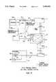
- FIG. 1.shows a telephone system in accordance with a first embodiment of the present invention
- FIG. 2shows a flow chart of the operation of the system of FIG. 1;
- FIG. 3shows a telephone system in accordance with a second embodiment of the present invention.
- FIG. 4shows a flow chart of the operation of the system of FIG. 3.
- FIG. 1shows a telephone system 1 in accordance with the principles of the present invention.
- the telephone system 1comprises a central office switch 2, shown as a program driven digital switch (e.g., an AT&T No. 5 ESS).
- the switch 2includes a switching network 2A and a program controlled processor 2B. The latter controls the switching network 2A so as to provide voice path connections for communicating with subscriber locations 3 served by the switch. Communication between each subscriber location 3 and the switching network 2A occurs via a line unit 4, a digital loop carrier 5 at the switch location, a transmission path 6 (shown as a T1 carrier), a digital loop carrier 7 at a remote location and a subscriber line 8.
- a line unit 4a digital loop carrier 5 at the switch location
- a transmission path 6shown as a T1 carrier
- a digital loop carrier 7at a remote location and a subscriber line 8.
- the central office switch 2is also coupled via simplified message desk interface links 9 to a voice message system 11.
- the voice message system 11permits the telephone system to provide a voice message service for the subscriber locations 3. Subscriber locations 3 which subscribe to the voice message service can have their unanswered telephone calls directed to the voice message system 11 where they are recorded. The subscriber locations 3 can then listen to these recorded messages by accessing the voice message system when they go off-hook at their telephone stations 3A.
- the voice message systemsends a message waiting indicator request or signal over the simplified message desk interface links 9 to the switch 2.
- This requestincludes the telephone number of the subscriber location and instructs the switch to transmit a stutter dial tone to the subscriber location when the location goes off-hook.
- an audible messageis established, i.e., the stutter dial tone, indicated by dashed path 12 in FIG. 1, by which the off-hook subscriber location can recognize that a voice message is waiting.
- the subscriber locationcan then query the voice message system 11 to retrieve the recorded message.
- the subscriber locations 3must go off-hook before they are alerted that a message is waiting on the voice message system 11.
- a subscriber locationmust thus go off-hook periodically in order to be sure that it has no waiting messages. Such a procedure becomes burdensome and is often not followed, resulting in delays in a subscriber location obtaining and responding to recorded messages.
- the aforesaid drawback of the system 1is overcome by further adapting the system such that the existence of waiting messages at the voice message system 11 can be indicated visually at the subscriber locations 3. Moreover, this is accomplished without substantial ringing (i.e., with no ringing or only minimal ringing) at the subscriber locations so that no or little disturbance occurs at the locations.
- the system 1is further adapted to include a control system 13 which is configured to establish suppressed ringing connections through the switch 2 to the subscriber locations 3. These connections are established by the control system 13 in response to message waiting indicator requests associated with (and in the present illustrative example) developed by the voice message system 11.
- the control system 13is adapted to transmit over the suppressed ringing connections visual message waiting indicator requests or signals. These requests are received at the subscriber locations 3 by visual message waiting indicator interfaces 3B. These interfaces, in turn, respond to the requests by activating visual indicators 3C (e.g., lamps) to indicate the presence of a waiting message at the voice message system 11. In FIG. 1, the path in the system 1 for establishing such visual indication for waiting messages is shown by dotted line 13A.
- visual indicators 3Ce.g., lamps
- the control system 13includes a central office service unit 14 and associated trunks 15.
- the unit 14 and the trunks 15control the trunk unit 2C of the switch 2 to establish the desired suppressed ringing connections to the subscriber locations 3.
- the unit 14 and trunks 15can be similar to the central office service unit and utility telemetry trunks, respectively, described in the telemetry system of European Published Patent Application 0 474 407 A1, the teachings of which are incorporated herein by reference.
- the trunks 15have a class of service which identifies to the switch 2 that the connections being requested by the central office service unit 14 are to be made with ringing suppressed, i.e., with no ringing signal transmitted or with a burst of ringing signal transmitted of sufficient length to activate the digital loop carriers but of insufficient length to be present for any significant time after connection is completed. Accordingly, the central office service unit 14 can establish connections through the switch 2 to the subscriber locations 3 which are accompanied by no or little (i.e., short) ringing.
- the visual message waiting indicator interface 3B used at the subscriber locationscan also operate similarly to the meter interface units used in the '407 patent application.
- each interface unit 3Bcan respond to control messages (analog tone messages over lines 8 as defined in Bellcore Technical Reference TR-TSY-000030 from the central office service unit 14 to activate or alert the unit as well as to cause the unit to activate the corresponding visual indicator 3C.
- a control computer 16 of the control system 13is used to monitor the message waiting indicator requests on the simplified message desk indicator links 9.
- the control computer 16then generates corresponding visual message waiting indicator requests and transmits these requests to the central office service unit 14 via communication links 17.
- the unit 14thereupon sets up the suppressed ringing connections to the appropriate subscriber locations 3, causing the indicator requests to be transmitted to the interfaces 3B.
- the interfaces and their associated visual indicators 3Care thereby activated.
- control system 13can be described in conjunction with the flow chart of FIG. 2.
- the voice message system 11transmits on the links 9 a message waiting indicator request associated with a particular subscriber location 3 having a message waiting at the voice message system 11. This is indicated in the request, as above-noted, by the telephone number of the subscriber location.
- the control computer 16receives or monitors this request in step 21, causing it to initiate its message waiting processing.
- step 22the central processing unit 16A of the control computer 16 verifies, via the telephone number contained in the request and via its data base 16B, whether the subscriber location 3 subscribes to the visual message waiting indicating service. If the subscriber location does not subscribe to this service, the process proceeds to step 23 wherein the message waiting indicator request is sent to the switch 2. If control computer 16 is configured to monitor the request, the request is allowed to pass on normally to provide stutter dial tone message waiting indication only. If the control computer 16 is configured to process the request, the request is processed true to provide stutter dial tone message waiting indication only.
- step 24If the subscriber location subscribes to the visual message waiting service, the process moves to step 24 wherein the control computer 16 again sends the message waiting indicator request to the switch 2.
- step 25if the switch 2 is unavailable for processing the message waiting request, then the switch either fails to acknowledge receipt of the message waiting request or sends a response indicating that the message waiting request was not processed. In such case process moves to step 26B, in which a message is sent to the voice message system 11 indicating that the switch 2 is unavailable. The voice message system 11 will thereupon attempt to resend the request until the message waiting request is processed.
- step 26Athe control computer sends a message to the central office service unit 14 requesting that a suppressed ringing connection be established to the appropriate subscriber location for visual message waiting indicator service.
- This message to the unit 14includes the telephone number of the subscriber location and the identity of the type of loop carrier in the connecting path to the subscriber location.
- step 27the service unit 14 sends a message containing similar information to the trunk unit 2C of the switch 2 instructing the switch to make the appropriate suppressed ringing connection.
- step 28if the switch and/or subscriber location are unavailable, a no connect message is sent to the control computer 16 in step 29.
- the no connect messagereturns the process to step 26B, causing a message to be sent to the voice message system 11 that the switch 2 is unavailable.
- the voice message systemwill then again attempt to periodically resend the message waiting indicator request until the process can be completed.
- the service unit 14transmits a visual message waiting indicator request to the trunk unit 2C in step 31. This message is transmitted to the visual message waiting interface unit 3B causing the interface and the visual indicator 3C at the subscriber location 3 to be activated.
- a subscriber location 3When a subscriber location 3 responds to an activated visual indicator 3C by going off-hook, the subscriber location first hears stutter dial tone which confirms the visual indication and results from the audible message waiting indicating service as discussed above. The subscriber location 3 then accesses the recorded messages from the voice message system.
- the voice message system 11After the subscriber location 3 accesses the voice message system 11 (e.g., after message retrieval and going on-hook), the voice message system 11 sends a completion request to the switch 2 instructing the switch 2 to provide normal or continuous dial tone to the subscriber location 3.
- the control computer 16monitors this completion request on the links 9 and upon receipt of the completion request sends a completion message to the central office service unit 14. This message causes the unit 14 to establish a suppressed ringing connection over which the completion message is transmitted to the interface unit 3B at the subscriber location 3.
- the completion messageinstructs the interface to deactivate the visual indicator 3C which is then deactivated.
- the message waiting indicator interfaces 3Bcan be provided with an accessible deactivator button 3D which when pressed causes the interface to deactivate the corresponding visual indicator 3C.
- a subscriber location 3after retrieving any waiting messages, can then activate the button 3D and deactivate the indicator 3C.
- the service unit 14communicates this busy condition to the control computer 16.
- the control computer 16communicates this condition to the voice message system 11 which then knows that the visual indicator 3C at the subscriber location 3 has not been activated.
- the voice message system 11will then retry to establish a connection by periodically transmitting a further voice message waiting indicator request.
- FIG. 3shows a second embodiment of a telephone system 1 in accordance with the principles of the present invention.
- a centralized control computer 31is used to control central office service unit 14.
- the centralized control computer 31communicates with the voice message system 11 over standard public telephone communication links 32.
- the centralized control computer 31can be a telemetry network access computer ("TNAC") which provides telemetry control for a number of central office service units which are part of a telemetry system of the type described in the '407 application.
- TNACtelemetry network access computer
- the central office service unit 14can also be part of the telemetry system and provide suppressed ringing connections to the subscriber locations 3 for telemetry purposes, as well as for visual message waiting indicator purposes in accordance with the present invention.
- the interface 3Bmight be part of a meter interface unit of the type also described in the '407 application.
- the voice message system 11sends separate visual message waiting indicating requests to the centralized control computer 31 for establishing the visual message waiting indications at the subscriber locations 3.
- the system 11also sends separate message waiting indicator requests over the simplified message desk .interface links 9 to establish for the subscriber locations audible, i.e., stutter dial tone, message waiting indications at these locations.
- the voice message system 11transmits its requests to the centralized control computer 31 over data links, shown as standard public packet switched network interface links 32 of the telephone system 1. Similarly, the messages transmitted between the centralized control computer 31 and the central office service unit 14 are also over data links, again shown as public packet switched network interface links.
- FIG. 4depicts a flow diagram showing the operation of the system 1 of FIG. 3 to establish a visual indication of a waiting message at a subscriber location 3.
- the voice message system 11transmits a message waiting indicator request or signal over the public packet switched network links 32 to the centralized control computer 31 instructing it to initiate its visual message waiting indicator processing.
- the central processing unit 31A of the centralized control computer 31determines from the telephone number in the request and from its data base 31B that it must transmit message waiting indicator messages to the central office service unit 14 serving the subscriber location 3 whose visual indicator is to be activated. The centralized control computer 31 then determines the routing to be used for these messages and a message containing the telephone number and loop carrier identification is transmitted.
- step 43the central office service unit 14, upon receipt of the transmitted message, sends a message to the switch 2 with the same information, i.e., telephone number and identification code, instructing the switch 2 to make a suppressed ringing connection.
- the same informationi.e., telephone number and identification code
- step 44if the switch 2 cannot make the connection, process moves to step 45 wherein the central office service unit 14 sends a message to centralized control computer 31 indicating that the connection cannot be made. Process then moves to step 46 wherein the centralized control computer sends a message to the voice message system indicating that acknowledgement from the switch 2 has not been received. In this case, the voice message system 11 will retry periodically to resend the message waiting indicator request to the central computer 31 to establish the connection and activate the visual indicator at the subscriber location.
- step 44If a connection is made in step 44, process moves to step 47 wherein the centralized control computer 31 sends a visual message waiting indicator signal over the established connection to the subscriber location. This message activates the associated interface 3B and visual indicator 3C so that the desired visual indication of the waiting message results.
- the deactivation of the visual indicator 3C at a subscriber location 3can be accomplished in a similar manner as in the embodiment of FIG. 1.
- the voice message system 11After the voice message system 11 has been accessed by the subscriber location (e.g., completes retrieval of its recorded messages), the voice message system sends a completion message to the centralized control computer 31.
- the centralized control computer 31then sends a corresponding message to the central office service unit 14.
- a deactivation button 3D on the interface 3Bcan be used to deactivate the indicator 3C.
- the central office service unit 14attempts to establish a suppressed ringing connection through the switch 2 to a subscriber location 3 that is busy, this condition is reported by the switch to the service unit.
- the service unitreports the busy condition to the centralized control computer 31 which reports the condition to the voice message system 11.
- the voice message system 11will then retry to complete the visual message waiting indication process by periodically sending a further voice message waiting indicator request.
- the simplified message desk protocol used to communicate between the voice message system and the centralized control computer 31has to be modified from the standard format to support positive acknowledgement. Also, the voice message system 11 has to be adapted to maintain records of visual message waiting requirements.
- the voice message system 11can be a standard system.
- the local control computer 16requires hardware sufficient to accommodate monitoring of the simplified message desk interface links 9.
- the trunks 15 and trunk unit 2C of the system 1can be adapted to include a so-called "barge in” capability (i.e., a capability similar to that currently used to send specific tones like Call Waiting Tone to a busy line during an on-going or active call).
- a so-called "barge in” capabilityi.e., a capability similar to that currently used to send specific tones like Call Waiting Tone to a busy line during an on-going or active call.
- the switch 2is then directed to send a unique visual message waiting tone (like a Call Waiting tone) over the active connection onto the busy or active subscriber line 8 of the subscriber location 3.
- a unique visual message waiting tonelike a Call Waiting tone
- the switch 2could bridge the central office service unit 14 onto the active connection and active subscriber line 8 and the central office service unit could place such tone thereon. In each case, the tone would be transmitted only over the active connection to the subscriber line 8 and not onto the line which is in communication with such subscriber line.
- the interface unit 3Breceives this tone and, in response thereto, the interface unit activates the indicator 3C at the subscriber location.
- the busy condition of the subscriber location 3would not interfere with visual message waiting indicator processing and this procedure would eliminate the need for the voice message system to resend requests to complete the process.
- Another alternative mode of operation of the system 1 in the case of a busy subscriber locationis to adapt the switch 2 so that its Automatic Callback function is brought into operation.
- the Automatic Callback function of the switch 2activates, causing the switch to send over the trunks 15 to the central office service unit 14 a message containing the directory number of the particular subscriber location.
- the central office service unit 14then sends the number to the control computer (either computer 16 or 31) which would retransmit a message waiting indicator request with the identified directory number back to the central office service unit 14.
- the service unitthen attempts to make the suppressed ring connection as previously discussed above to provide the visual message waiting indicator activation.
- the system 1can be adapted to include an Advance Intelligent Network (AIN) function similar to the Automatic Callback function which establishes a trigger on a subscriber location line 8 when a suppressed ringing connection has been tried and the subscriber location is busy.
- AINAdvance Intelligent Network
- the AIN triggeractivates the function which sends a message to the central office service unit 14 over the trunks 15 (or over a data network such as a public packet switched network) containing the telephone number of the subscriber location.
- This informationmay be stored either internally to the switch 2 or using an external data base.
- the central office service unit 14then reacts as in the previous case to report this to the control computer.
- the control computerthen proceeds by sending a message waiting indicator request to the service unit 14 to establish the suppressed ringing connection and visual message waiting indication.
- the telephone system of the inventioncan be modified such that the voice message system 11 communicates directly with the trunk unit 2C of the switch 2 to establish the suppressed ringing connections and the visual message waiting indication.
- the voice message systemmust be configured to accommodate the protocol of the trunk unit messages.
- the inventioncan be practiced by sending a very brief ringing signal to the subscriber locations, instead of entirely suppressing any ringing. This can be established by controlling the processing for the suppressed ringing connection so that a brief ringing is present after a connection is established.
Landscapes
- Engineering & Computer Science (AREA)
- Signal Processing (AREA)
- Telephonic Communication Services (AREA)
Abstract
Description
Claims (41)
Priority Applications (2)
| Application Number | Priority Date | Filing Date | Title |
|---|---|---|---|
| US07/995,025US5363431A (en) | 1992-12-22 | 1992-12-22 | Visual message waiting indication in a telephone voice message system |
| US08/330,690US5521964A (en) | 1992-12-22 | 1994-10-28 | Visual message waiting indication in a telephone voice message system |
Applications Claiming Priority (1)
| Application Number | Priority Date | Filing Date | Title |
|---|---|---|---|
| US07/995,025US5363431A (en) | 1992-12-22 | 1992-12-22 | Visual message waiting indication in a telephone voice message system |
Related Child Applications (1)
| Application Number | Title | Priority Date | Filing Date |
|---|---|---|---|
| US08/330,690Continuation-In-PartUS5521964A (en) | 1992-12-22 | 1994-10-28 | Visual message waiting indication in a telephone voice message system |
Publications (1)
| Publication Number | Publication Date |
|---|---|
| US5363431Atrue US5363431A (en) | 1994-11-08 |
Family
ID=25541315
Family Applications (1)
| Application Number | Title | Priority Date | Filing Date |
|---|---|---|---|
| US07/995,025Expired - LifetimeUS5363431A (en) | 1992-12-22 | 1992-12-22 | Visual message waiting indication in a telephone voice message system |
Country Status (1)
| Country | Link |
|---|---|
| US (1) | US5363431A (en) |
Cited By (60)
| Publication number | Priority date | Publication date | Assignee | Title |
|---|---|---|---|---|
| US5521964A (en)* | 1992-12-22 | 1996-05-28 | Bellsouth Corporation | Visual message waiting indication in a telephone voice message system |
| WO1996032803A1 (en)* | 1995-04-13 | 1996-10-17 | Active Voice Corporation | Method and aparatus for monitoring a message in a voice mail system |
| WO1998007266A1 (en)* | 1996-08-14 | 1998-02-19 | Northern Telecom Limited | Internet-based telephone call manager |
| US5802155A (en)* | 1995-11-15 | 1998-09-01 | Lucent Techologies Inc. | Method and apparatus for controlling regular and supressed ringing connections in a telecommunications network |
| US5809128A (en)* | 1996-11-01 | 1998-09-15 | Interactive Telecom Inc. | Method and apparatus permitting notification and control of blocked incoming calls over a data network |
| US5812656A (en)* | 1995-11-15 | 1998-09-22 | Lucent Technologies, Inc. | System for providing prioritized connections in a public switched network |
| US5825849A (en)* | 1995-08-31 | 1998-10-20 | Lucent Technologies, Inc. | Loop-back test system using a suppressed ringing connection |
| US6169796B1 (en) | 1998-03-09 | 2001-01-02 | At & T Corp. | Call rerouter method and apparatus |
| US6181928B1 (en)* | 1997-08-21 | 2001-01-30 | Ericsson Inc. | Method and apparatus for event notification for wireless devices |
| US6253249B1 (en) | 1998-08-31 | 2001-06-26 | Nortel Networks Limited | Method and devices for bridging data and telephone networks |
| US6252952B1 (en) | 1999-12-30 | 2001-06-26 | At&T Corp | Personal user network (closed user network) PUN/CUN |
| US6292544B1 (en)* | 1998-04-06 | 2001-09-18 | Ag Communcation Systems Corporation | Message waiting indicator in a computer integrated telephony system |
| US6304636B1 (en) | 1997-12-23 | 2001-10-16 | At&T Corp. | Forwarding voice messages to a called party using electronic mail |
| US6304565B1 (en) | 1998-05-20 | 2001-10-16 | At&T Corp. | Method of completing long distance pots calls with IP telephony endpoints |
| US6343115B1 (en) | 1996-02-13 | 2002-01-29 | At&T Corp | Method of announcing an internet call |
| US6343121B1 (en) | 1998-06-29 | 2002-01-29 | At&T Corp | Selective call waiting service |
| US6353611B1 (en) | 1995-11-27 | 2002-03-05 | At&T Corp. | Call waiting feature for a telephone line connected to the internet |
| US6373817B1 (en) | 1999-12-30 | 2002-04-16 | At&T Corp. | Chase me system |
| US6393467B1 (en) | 1998-08-31 | 2002-05-21 | Nortel Networks Limited | Network interconnected computing device, server and notification method |
| US6393122B1 (en) | 1998-08-31 | 2002-05-21 | Nortel Networks Limited | Method and device for providing intermediate telephone service with enhanced network reliability |
| US6404874B1 (en) | 1997-03-27 | 2002-06-11 | Cisco Technology, Inc. | Telecommute server |
| US6438222B1 (en) | 1998-12-23 | 2002-08-20 | At&T Corp. | Method and system for processing a telephone call while on-line |
| US6449246B1 (en) | 1999-09-15 | 2002-09-10 | Telcordia Technologies, Inc. | Multicarrier personal access communication system |
| US6532286B1 (en) | 1998-12-23 | 2003-03-11 | At&T Corp. | Method and system for processing a telephone call |
| US6570855B1 (en) | 1999-12-30 | 2003-05-27 | At&T Corp. | Automatic call manager traffic gate feature |
| US6633635B2 (en) | 1999-12-30 | 2003-10-14 | At&T Corp. | Multiple call waiting in a packetized communication system |
| US6643358B2 (en) | 1998-05-27 | 2003-11-04 | 3Com Corporation | Telephone answering apparatus and method for confirming an acoustic command signal |
| US6671262B1 (en) | 1999-12-30 | 2003-12-30 | At&T Corp. | Conference server for automatic x-way call port expansion feature |
| US6678265B1 (en) | 1999-12-30 | 2004-01-13 | At&T Corp. | Local number portability database for on-net IP call |
| US6680935B1 (en) | 1999-12-30 | 2004-01-20 | At&T Corp. | Anonymous call rejection |
| US6687360B2 (en) | 1999-12-30 | 2004-02-03 | At&T Corp. | Personal IP follow-me service |
| US6690675B1 (en) | 1999-12-30 | 2004-02-10 | At&T Corp. | User programmable fail-proof IP hotline/warm-line |
| US6721415B1 (en) | 2000-02-17 | 2004-04-13 | Bellsouth Intellectual Property Corporation | Telephone voice messaging system and method using off-hook immediate trigger |
| US6728239B1 (en) | 1999-12-30 | 2004-04-27 | At&T Corp. | Scaleable network server for low cost PBX |
| US6775267B1 (en) | 1999-12-30 | 2004-08-10 | At&T Corp | Method for billing IP broadband subscribers |
| US6775273B1 (en) | 1999-12-30 | 2004-08-10 | At&T Corp. | Simplified IP service control |
| US6801952B2 (en) | 1998-08-31 | 2004-10-05 | Nortel Networks Limited | Method and devices for providing network services from several servers |
| US6816469B1 (en) | 1999-12-30 | 2004-11-09 | At&T Corp. | IP conference call waiting |
| US6826173B1 (en) | 1999-12-30 | 2004-11-30 | At&T Corp. | Enhanced subscriber IP alerting |
| US6836478B1 (en) | 1999-12-30 | 2004-12-28 | At&T Corp. | Call hold with reminder and information push |
| US6868155B1 (en)* | 1999-04-27 | 2005-03-15 | Agere Systems Inc. | Off-hook visual message waiting indicator |
| US6889321B1 (en) | 1999-12-30 | 2005-05-03 | At&T Corp. | Protected IP telephony calls using encryption |
| US20050094779A1 (en)* | 2002-07-25 | 2005-05-05 | Bellsouth Intellectual Property Corporation | System and method for efficient provision of a voicemail message indicator signal over a computer data network |
| US6917610B1 (en) | 1999-12-30 | 2005-07-12 | At&T Corp. | Activity log for improved call efficiency |
| US6937713B1 (en) | 1999-12-30 | 2005-08-30 | At&T Corp. | IP call forward profile |
| US20060056388A1 (en)* | 2004-08-24 | 2006-03-16 | Comcast Cable Holdings, Llc | Method and system for locating a voice over internet protocol (VoIP) device connected to a network |
| US7027567B1 (en)* | 2001-06-28 | 2006-04-11 | Bellsouth Intellectual Property Corporation | System and method for electronic message status notification and reply using various electronic media |
| US7075918B1 (en) | 1999-12-30 | 2006-07-11 | At&T Corp. | BRG with PBX capabilities |
| US7120139B1 (en) | 1999-12-30 | 2006-10-10 | At&T Corp. | Broadband cable telephony network architecture IP ITN network architecture reference model |
| US7130388B1 (en)* | 2001-01-11 | 2006-10-31 | America Online, Inc. | Portable message waiting indicator |
| US7180889B1 (en) | 1999-12-30 | 2007-02-20 | At&T Corp. | Personal control of address assignment and greeting options for multiple BRG ports |
| US7295660B1 (en) | 2003-10-23 | 2007-11-13 | Aol Llc | Telemarketer screening |
| US20100195541A1 (en)* | 2009-01-30 | 2010-08-05 | Embarq Holdings Company, Llc | System, Method and Apparatus for Providing Simulated Stutter Dial Tone from an IP End Point Device |
| US8094800B1 (en) | 2004-12-21 | 2012-01-10 | Aol Inc. | Call treatment based on user association with one or more user groups |
| US8938062B2 (en) | 1995-12-11 | 2015-01-20 | Comcast Ip Holdings I, Llc | Method for accessing service resource items that are for use in a telecommunications system |
| US9191505B2 (en) | 2009-05-28 | 2015-11-17 | Comcast Cable Communications, Llc | Stateful home phone service |
| US9286294B2 (en) | 1992-12-09 | 2016-03-15 | Comcast Ip Holdings I, Llc | Video and digital multimedia aggregator content suggestion engine |
| US9813641B2 (en) | 2000-06-19 | 2017-11-07 | Comcast Ip Holdings I, Llc | Method and apparatus for targeting of interactive virtual objects |
| US10140433B2 (en) | 2001-08-03 | 2018-11-27 | Comcast Ip Holdings I, Llc | Video and digital multimedia aggregator |
| US10349096B2 (en) | 2001-08-03 | 2019-07-09 | Comcast Ip Holdings I, Llc | Video and digital multimedia aggregator content coding and formatting |
Citations (5)
| Publication number | Priority date | Publication date | Assignee | Title |
|---|---|---|---|---|
| US4453041A (en)* | 1980-03-31 | 1984-06-05 | Marcelo Castro | Method and apparatus for processing coded information received through a telephone line during the non-active intervals of a ringing period |
| US4468541A (en)* | 1983-07-21 | 1984-08-28 | Timex Corporation | Terminal equipment ring/ding suppression circuit |
| US4853952A (en)* | 1987-12-03 | 1989-08-01 | Dictaphone Corporation | Method and apparatus for visual indication of stored voice signals |
| US4969186A (en)* | 1988-05-12 | 1990-11-06 | Gte North Incorporated | Telephone message waiting system and apparatus |
| EP0474407A1 (en)* | 1990-08-31 | 1992-03-11 | AT&T Corp. | Telemetry access arrangement |
- 1992
- 1992-12-22USUS07/995,025patent/US5363431A/ennot_activeExpired - Lifetime
Patent Citations (5)
| Publication number | Priority date | Publication date | Assignee | Title |
|---|---|---|---|---|
| US4453041A (en)* | 1980-03-31 | 1984-06-05 | Marcelo Castro | Method and apparatus for processing coded information received through a telephone line during the non-active intervals of a ringing period |
| US4468541A (en)* | 1983-07-21 | 1984-08-28 | Timex Corporation | Terminal equipment ring/ding suppression circuit |
| US4853952A (en)* | 1987-12-03 | 1989-08-01 | Dictaphone Corporation | Method and apparatus for visual indication of stored voice signals |
| US4969186A (en)* | 1988-05-12 | 1990-11-06 | Gte North Incorporated | Telephone message waiting system and apparatus |
| EP0474407A1 (en)* | 1990-08-31 | 1992-03-11 | AT&T Corp. | Telemetry access arrangement |
Cited By (97)
| Publication number | Priority date | Publication date | Assignee | Title |
|---|---|---|---|---|
| US9286294B2 (en) | 1992-12-09 | 2016-03-15 | Comcast Ip Holdings I, Llc | Video and digital multimedia aggregator content suggestion engine |
| US5521964A (en)* | 1992-12-22 | 1996-05-28 | Bellsouth Corporation | Visual message waiting indication in a telephone voice message system |
| WO1996032803A1 (en)* | 1995-04-13 | 1996-10-17 | Active Voice Corporation | Method and aparatus for monitoring a message in a voice mail system |
| US5651054A (en)* | 1995-04-13 | 1997-07-22 | Active Voice Corporation | Method and apparatus for monitoring a message in a voice mail system |
| EP0760570A3 (en)* | 1995-08-31 | 2000-01-19 | AT&T Corp. | Loop-back test system using a suppressed ringing connection |
| US5825849A (en)* | 1995-08-31 | 1998-10-20 | Lucent Technologies, Inc. | Loop-back test system using a suppressed ringing connection |
| US5802155A (en)* | 1995-11-15 | 1998-09-01 | Lucent Techologies Inc. | Method and apparatus for controlling regular and supressed ringing connections in a telecommunications network |
| US5812656A (en)* | 1995-11-15 | 1998-09-22 | Lucent Technologies, Inc. | System for providing prioritized connections in a public switched network |
| US6842448B1 (en) | 1995-11-27 | 2005-01-11 | At&T Corp. | Call waiting feature for a telephone line connected to the internet |
| US6961333B2 (en) | 1995-11-27 | 2005-11-01 | At&T Corp | Call waiting feature for a telephone line connected to the internet |
| US6353611B1 (en) | 1995-11-27 | 2002-03-05 | At&T Corp. | Call waiting feature for a telephone line connected to the internet |
| US8938062B2 (en) | 1995-12-11 | 2015-01-20 | Comcast Ip Holdings I, Llc | Method for accessing service resource items that are for use in a telecommunications system |
| US6343115B1 (en) | 1996-02-13 | 2002-01-29 | At&T Corp | Method of announcing an internet call |
| WO1998007266A1 (en)* | 1996-08-14 | 1998-02-19 | Northern Telecom Limited | Internet-based telephone call manager |
| US8189747B1 (en) | 1996-08-14 | 2012-05-29 | Rockstar Bidco, LP | Internet-based telephone call manager |
| US6212261B1 (en) | 1996-08-14 | 2001-04-03 | Nortel Networks Limited | Internet-based telephone call manager |
| US5809128A (en)* | 1996-11-01 | 1998-09-15 | Interactive Telecom Inc. | Method and apparatus permitting notification and control of blocked incoming calls over a data network |
| US6404874B1 (en) | 1997-03-27 | 2002-06-11 | Cisco Technology, Inc. | Telecommute server |
| US6181928B1 (en)* | 1997-08-21 | 2001-01-30 | Ericsson Inc. | Method and apparatus for event notification for wireless devices |
| US6304636B1 (en) | 1997-12-23 | 2001-10-16 | At&T Corp. | Forwarding voice messages to a called party using electronic mail |
| US6687340B1 (en) | 1997-12-23 | 2004-02-03 | At&T Corp. | Forwarding voice messages to a called party using electronic mail |
| US6169796B1 (en) | 1998-03-09 | 2001-01-02 | At & T Corp. | Call rerouter method and apparatus |
| US6292544B1 (en)* | 1998-04-06 | 2001-09-18 | Ag Communcation Systems Corporation | Message waiting indicator in a computer integrated telephony system |
| US6304565B1 (en) | 1998-05-20 | 2001-10-16 | At&T Corp. | Method of completing long distance pots calls with IP telephony endpoints |
| US6643358B2 (en) | 1998-05-27 | 2003-11-04 | 3Com Corporation | Telephone answering apparatus and method for confirming an acoustic command signal |
| US6343121B1 (en) | 1998-06-29 | 2002-01-29 | At&T Corp | Selective call waiting service |
| US7848506B1 (en) | 1998-06-29 | 2010-12-07 | At&T Intellectual Property Ii, L.P. | Selective call waiting service |
| US7099452B1 (en) | 1998-06-29 | 2006-08-29 | At&T Corp. | Selective call waiting service |
| US6738467B1 (en) | 1998-06-29 | 2004-05-18 | At&T Corp. | Selective call waiting service |
| US6393122B1 (en) | 1998-08-31 | 2002-05-21 | Nortel Networks Limited | Method and device for providing intermediate telephone service with enhanced network reliability |
| US6393467B1 (en) | 1998-08-31 | 2002-05-21 | Nortel Networks Limited | Network interconnected computing device, server and notification method |
| US6801952B2 (en) | 1998-08-31 | 2004-10-05 | Nortel Networks Limited | Method and devices for providing network services from several servers |
| US6253249B1 (en) | 1998-08-31 | 2001-06-26 | Nortel Networks Limited | Method and devices for bridging data and telephone networks |
| US6532286B1 (en) | 1998-12-23 | 2003-03-11 | At&T Corp. | Method and system for processing a telephone call |
| US6438222B1 (en) | 1998-12-23 | 2002-08-20 | At&T Corp. | Method and system for processing a telephone call while on-line |
| US6775370B2 (en) | 1998-12-23 | 2004-08-10 | At&T Corp. | Method and system for processing a telephone call while on-line |
| US6868155B1 (en)* | 1999-04-27 | 2005-03-15 | Agere Systems Inc. | Off-hook visual message waiting indicator |
| US6449246B1 (en) | 1999-09-15 | 2002-09-10 | Telcordia Technologies, Inc. | Multicarrier personal access communication system |
| US7075918B1 (en) | 1999-12-30 | 2006-07-11 | At&T Corp. | BRG with PBX capabilities |
| US6937713B1 (en) | 1999-12-30 | 2005-08-30 | At&T Corp. | IP call forward profile |
| US6775273B1 (en) | 1999-12-30 | 2004-08-10 | At&T Corp. | Simplified IP service control |
| US6690675B1 (en) | 1999-12-30 | 2004-02-10 | At&T Corp. | User programmable fail-proof IP hotline/warm-line |
| US8711735B2 (en) | 1999-12-30 | 2014-04-29 | At&T Intellectual Property, Ii, L.P. | Personal IP toll-free number |
| US6687360B2 (en) | 1999-12-30 | 2004-02-03 | At&T Corp. | Personal IP follow-me service |
| US6816469B1 (en) | 1999-12-30 | 2004-11-09 | At&T Corp. | IP conference call waiting |
| US6826173B1 (en) | 1999-12-30 | 2004-11-30 | At&T Corp. | Enhanced subscriber IP alerting |
| US6836478B1 (en) | 1999-12-30 | 2004-12-28 | At&T Corp. | Call hold with reminder and information push |
| US6680935B1 (en) | 1999-12-30 | 2004-01-20 | At&T Corp. | Anonymous call rejection |
| US6678265B1 (en) | 1999-12-30 | 2004-01-13 | At&T Corp. | Local number portability database for on-net IP call |
| US6889321B1 (en) | 1999-12-30 | 2005-05-03 | At&T Corp. | Protected IP telephony calls using encryption |
| US8666053B2 (en) | 1999-12-30 | 2014-03-04 | Shoretel, Inc. | System with call forward profile |
| US6917610B1 (en) | 1999-12-30 | 2005-07-12 | At&T Corp. | Activity log for improved call efficiency |
| US6373817B1 (en) | 1999-12-30 | 2002-04-16 | At&T Corp. | Chase me system |
| US6671262B1 (en) | 1999-12-30 | 2003-12-30 | At&T Corp. | Conference server for automatic x-way call port expansion feature |
| US9167097B2 (en) | 1999-12-30 | 2015-10-20 | Shoretel, Inc. | Responding to a call with a prompt and routing the call to a phone selected in response to the prompt |
| US8514846B2 (en) | 1999-12-30 | 2013-08-20 | Shoretel, Inc. | Responding to IP call with a prompt to select an extension and routing packets to IP phone at selected extension |
| US6775267B1 (en) | 1999-12-30 | 2004-08-10 | At&T Corp | Method for billing IP broadband subscribers |
| US6252952B1 (en) | 1999-12-30 | 2001-06-26 | At&T Corp | Personal user network (closed user network) PUN/CUN |
| US9300699B2 (en) | 1999-12-30 | 2016-03-29 | Shoretel, Inc. | System with call forward profile |
| US7120139B1 (en) | 1999-12-30 | 2006-10-10 | At&T Corp. | Broadband cable telephony network architecture IP ITN network architecture reference model |
| US8054963B2 (en) | 1999-12-30 | 2011-11-08 | Shoretel, Inc. | System with call forward profile |
| US7180889B1 (en) | 1999-12-30 | 2007-02-20 | At&T Corp. | Personal control of address assignment and greeting options for multiple BRG ports |
| US6728239B1 (en) | 1999-12-30 | 2004-04-27 | At&T Corp. | Scaleable network server for low cost PBX |
| US6633635B2 (en) | 1999-12-30 | 2003-10-14 | At&T Corp. | Multiple call waiting in a packetized communication system |
| US6570855B1 (en) | 1999-12-30 | 2003-05-27 | At&T Corp. | Automatic call manager traffic gate feature |
| US20040190692A1 (en)* | 2000-02-17 | 2004-09-30 | Bellsouth Intellectual Property Corporation | Telephone voice messaging system and method using off-hook immediate trigger |
| US7023978B2 (en) | 2000-02-17 | 2006-04-04 | Bellsouth Intellectual Property Corp. | Telephone voice messaging system and method using off-hook immediate trigger |
| US6721415B1 (en) | 2000-02-17 | 2004-04-13 | Bellsouth Intellectual Property Corporation | Telephone voice messaging system and method using off-hook immediate trigger |
| US9813641B2 (en) | 2000-06-19 | 2017-11-07 | Comcast Ip Holdings I, Llc | Method and apparatus for targeting of interactive virtual objects |
| US20070121809A1 (en)* | 2001-01-11 | 2007-05-31 | Bell Ian A | Portable message waiting indicator |
| US7130388B1 (en)* | 2001-01-11 | 2006-10-31 | America Online, Inc. | Portable message waiting indicator |
| US7477729B2 (en) | 2001-01-11 | 2009-01-13 | Aol Llc | Portable message waiting indicator |
| US7027567B1 (en)* | 2001-06-28 | 2006-04-11 | Bellsouth Intellectual Property Corporation | System and method for electronic message status notification and reply using various electronic media |
| US10349096B2 (en) | 2001-08-03 | 2019-07-09 | Comcast Ip Holdings I, Llc | Video and digital multimedia aggregator content coding and formatting |
| US10140433B2 (en) | 2001-08-03 | 2018-11-27 | Comcast Ip Holdings I, Llc | Video and digital multimedia aggregator |
| US20050094779A1 (en)* | 2002-07-25 | 2005-05-05 | Bellsouth Intellectual Property Corporation | System and method for efficient provision of a voicemail message indicator signal over a computer data network |
| US7764770B2 (en)* | 2002-07-25 | 2010-07-27 | At&T Intellectual Property I, L.P. | System and method for efficient provision of a voicemail message indicator signal over a computer data network |
| US7295660B1 (en) | 2003-10-23 | 2007-11-13 | Aol Llc | Telemarketer screening |
| US7940746B2 (en) | 2004-08-24 | 2011-05-10 | Comcast Cable Holdings, Llc | Method and system for locating a voice over internet protocol (VoIP) device connected to a network |
| US9648644B2 (en) | 2004-08-24 | 2017-05-09 | Comcast Cable Communications, Llc | Determining a location of a device for calling via an access point |
| US9036626B2 (en) | 2004-08-24 | 2015-05-19 | Comcast Cable Holdings, Llc | Method and system for locating a voice over internet protocol (VOIP) device connected to a network |
| US9049132B1 (en) | 2004-08-24 | 2015-06-02 | Comcast Cable Holdings, Llc | Locating a voice over packet (VoP) device connected to a network |
| US9055550B1 (en) | 2004-08-24 | 2015-06-09 | Comcast Cable Holdings, Llc | Locating a voice over packet (VoP) device connected to a network |
| US8724522B2 (en) | 2004-08-24 | 2014-05-13 | Comcast Cable Holdings, Llc | Method and system for locating a voice over internet protocol (VoIP) device connected to a network |
| US11956852B2 (en) | 2004-08-24 | 2024-04-09 | Comcast Cable Communications, Llc | Physical location management for voice over packet communication |
| US20060056388A1 (en)* | 2004-08-24 | 2006-03-16 | Comcast Cable Holdings, Llc | Method and system for locating a voice over internet protocol (VoIP) device connected to a network |
| US11252779B2 (en) | 2004-08-24 | 2022-02-15 | Comcast Cable Communications, Llc | Physical location management for voice over packet communication |
| US10070466B2 (en) | 2004-08-24 | 2018-09-04 | Comcast Cable Communications, Llc | Determining a location of a device for calling via an access point |
| US10517140B2 (en) | 2004-08-24 | 2019-12-24 | Comcast Cable Communications, Llc | Determining a location of a device for calling via an access point |
| US20110116420A1 (en)* | 2004-08-24 | 2011-05-19 | Comcast Cable Communications, Llc | Method and System for Locating a Voice over Internet Protocol (VOIP) Device Connected to a Network |
| US9596348B2 (en) | 2004-12-21 | 2017-03-14 | Google Inc. | Call treatment based on user association with one or more user groups |
| US8094800B1 (en) | 2004-12-21 | 2012-01-10 | Aol Inc. | Call treatment based on user association with one or more user groups |
| US8406409B2 (en) | 2004-12-21 | 2013-03-26 | Marathon Solutions, LLC | Treatment of electronic communications based on user association with one or more online groups |
| US10389877B2 (en) | 2004-12-21 | 2019-08-20 | Google Llc | Call treatment based on user association with one or more user groups |
| US8514844B2 (en)* | 2009-01-30 | 2013-08-20 | Centurylink Intellectual Property Llc | System, method and apparatus for providing simulated stutter dial tone from an IP end point device |
| US20100195541A1 (en)* | 2009-01-30 | 2010-08-05 | Embarq Holdings Company, Llc | System, Method and Apparatus for Providing Simulated Stutter Dial Tone from an IP End Point Device |
| US9191505B2 (en) | 2009-05-28 | 2015-11-17 | Comcast Cable Communications, Llc | Stateful home phone service |
Similar Documents
| Publication | Publication Date | Title |
|---|---|---|
| US5363431A (en) | Visual message waiting indication in a telephone voice message system | |
| US5521964A (en) | Visual message waiting indication in a telephone voice message system | |
| US5924016A (en) | Control and monitoring apparatus and method for a telephone system | |
| US5790638A (en) | Signaling in call transfer calling operations to control the initiation of secondary number telephone service features | |
| US6104912A (en) | Meet-me telephone system with subscriber notification feature | |
| KR100245238B1 (en) | Method and apparatus for delivery of a response in a messaging system | |
| US6628768B1 (en) | System and method of responding to an incoming call while conferencing | |
| US6545589B1 (en) | Method and apparatus for managing telecommunications | |
| US5394461A (en) | Telemetry feature protocol expansion | |
| CA2183800C (en) | Call forwarding techniques using smart cards | |
| US6031905A (en) | Network-based call hold stand by | |
| AU679517B2 (en) | Telemetry arrangement | |
| CA2302029C (en) | Call related information receiver to receiver transfer | |
| US6389118B1 (en) | Methods and apparatus for connecting a telephone subscriber to a peripheral device | |
| JP2985134B2 (en) | Message transfer method | |
| US7054433B1 (en) | Method and apparatus for transmitting data without establishing a call path | |
| JP2002125056A (en) | Telephone charge saving function preformed through exchange system | |
| JPH01238257A (en) | Information accumulation and transferring equipment | |
| JPH10163951A (en) | Call processing method of wireless paging system |
Legal Events
| Date | Code | Title | Description |
|---|---|---|---|
| AS | Assignment | Owner name:BELL SOUTH CORPORATION, GEORGIA Free format text:ASSIGNMENT OF ASSIGNORS INTEREST.;ASSIGNORS:SCHULL, JEROME W.;HOWE, WAYNE R.;REEL/FRAME:006454/0959;SIGNING DATES FROM 19930216 TO 19930219 | |
| STCF | Information on status: patent grant | Free format text:PATENTED CASE | |
| CC | Certificate of correction | ||
| FEPP | Fee payment procedure | Free format text:PAYOR NUMBER ASSIGNED (ORIGINAL EVENT CODE: ASPN); ENTITY STATUS OF PATENT OWNER: LARGE ENTITY | |
| FPAY | Fee payment | Year of fee payment:4 | |
| AS | Assignment | Owner name:BELLSOUTH INTELLECTUAL PROPERTY GROUP, INC., GEORG Free format text:ASSIGNMENT OF ASSIGNORS INTEREST;ASSIGNOR:BELLSOUTH CORPORATION;REEL/FRAME:009670/0482 Effective date:19980901 Owner name:BELLSOUTH INTELLECTUAL PROPERTY CORPORATION, DELAW Free format text:ASSIGNMENT OF ASSIGNORS INTEREST;ASSIGNOR:BELLSOUTH INTELLECTUAL PROPERTY GROUP, INC.;REEL/FRAME:009678/0367 Effective date:19980901 | |
| FPAY | Fee payment | Year of fee payment:8 | |
| REMI | Maintenance fee reminder mailed | ||
| FPAY | Fee payment | Year of fee payment:12 | |
| AS | Assignment | Owner name:PHASE SYSTEMS LLC, DELAWARE Free format text:ASSIGNMENT OF ASSIGNORS INTEREST;ASSIGNOR:BELLSOUTH INTELLECTUAL PROPERTY CORPORATION;REEL/FRAME:019407/0079 Effective date:20060726 |