US5363120A - Computer input device using orientation sensor - Google Patents
Computer input device using orientation sensorDownload PDFInfo
- Publication number
- US5363120A US5363120AUS08/128,043US12804393AUS5363120AUS 5363120 AUS5363120 AUS 5363120AUS 12804393 AUS12804393 AUS 12804393AUS 5363120 AUS5363120 AUS 5363120A
- Authority
- US
- United States
- Prior art keywords
- input device
- housing
- recited
- axis
- computer
- Prior art date
- Legal status (The legal status is an assumption and is not a legal conclusion. Google has not performed a legal analysis and makes no representation as to the accuracy of the status listed.)
- Expired - Lifetime
Links
Images


Classifications
- G—PHYSICS
- G06—COMPUTING OR CALCULATING; COUNTING
- G06F—ELECTRIC DIGITAL DATA PROCESSING
- G06F3/00—Input arrangements for transferring data to be processed into a form capable of being handled by the computer; Output arrangements for transferring data from processing unit to output unit, e.g. interface arrangements
- G06F3/01—Input arrangements or combined input and output arrangements for interaction between user and computer
- G06F3/03—Arrangements for converting the position or the displacement of a member into a coded form
- G06F3/0304—Detection arrangements using opto-electronic means
- G06F3/0312—Detection arrangements using opto-electronic means for tracking the rotation of a spherical or circular member, e.g. optical rotary encoders used in mice or trackballs using a tracking ball or in mouse scroll wheels
- G—PHYSICS
- G06—COMPUTING OR CALCULATING; COUNTING
- G06F—ELECTRIC DIGITAL DATA PROCESSING
- G06F3/00—Input arrangements for transferring data to be processed into a form capable of being handled by the computer; Output arrangements for transferring data from processing unit to output unit, e.g. interface arrangements
- G06F3/01—Input arrangements or combined input and output arrangements for interaction between user and computer
- G06F3/03—Arrangements for converting the position or the displacement of a member into a coded form
- G06F3/033—Pointing devices displaced or positioned by the user, e.g. mice, trackballs, pens or joysticks; Accessories therefor
- G06F3/0346—Pointing devices displaced or positioned by the user, e.g. mice, trackballs, pens or joysticks; Accessories therefor with detection of the device orientation or free movement in a 3D space, e.g. 3D mice, 6-DOF [six degrees of freedom] pointers using gyroscopes, accelerometers or tilt-sensors
Definitions
- This inventionrelates to position or orientation sensors, and more particulary to an orientation sensor used to provide cursor control input to a computer system.
- cursor positioning devicesThere are various devices known for positioning or controlling the movement of a cursor on a computer display screen.
- the most common in useis the conventional "mouse" device, which takes the form of a hand-sized housing which is moved over a flat desktop. Motion over the desktop is sensed by means of a mechanically rotating ball or optically reflective sensor, and digital data are generated which translate into corresponding motion of the cursor on the display screen.
- cursor positioning devicesinclude the graphics input tablet which consists of a flat sensor pad and a hand-held pointing stylus which translates the analog motion of the pointing stylus into digitized data which is used to control the location of the cursor on the display screen.
- cursor movement devicesrely on focused light sources, held by the user or fixed on the user's person, as on a pilot's helmet. Sensors mounted around a display screen track the movement of the light beam and translate this movement into a corresponding movement of the cursor on the display screen.
- cursor positioning and controlling devicessuch as those discussed above are basically effective, although they suffer from certain disadvantages.
- Most cursor positioning and controlling deviceshave the disadvantage of requiring a fixed, generally level surface upon which to operate, or must operate in conjuction with a stationary sensor of some type; that is, motion is sensed with respect to a fixed medium and positional data signals are generated and presented to a computer for translation into a corresponding cursor movement.
- the need for a fixed surface or stationary sensorconstrains how the user may interact with the display device. The user must normally sit close to the display screen and be provided with ample level desk space for placement of the graphics tablet or movement of the "mouse.” In the case of the stationary sensor, the user must confine movement to keep the light beam within range of the sensor array.
- the present inventionovercomes the disadvantages of the prior art devices, such as the requirement for a flat desktop or confined movement of a user.
- a novel computer input devicefor a computer display unit having a display screen.
- the computer input deviceincludes an orientation sensor which generates an electrical signal representative of the physical orientation of the device, without it being adjacent to any fixed surface, and the electrical signal is used to position and otherwise control a cursor on the display screen.
- the computer input deviceis held in the user's hand, and by simple angular or rotational movements of the device, the user effects corresponding movement of the cursor.
- the orientation sensoroperates on the principle of a light beam being refracted as it passes from one transparent medium to another.
- the orientation sensorincludes a hollow spherical housing, with a defined vertical axis passing through its center point. Contained within the spherical housing are two fluid media. The first medium is gaseous and the second medium is liquid, and each has a predetermined viscosity and a different index of refraction. The liquid medium fills the spherical housing to the one-half level and the boundary between the liquid and gas intersects the center point of the spherical housing.
- a light source in the form of an LED, and a photodetector in the form of a phototransistorare mounted opposingly in the inner wall of the spherical housing on an axis that extends through the center point of the housing, such that light emitted from the light source must first pass through the center point of the spherical housing before being detected by the photodetector.
- the light sourceemits a focused beam and the photodetector receives the focused beam and generates an analog voltage representative of the intensity of the beam, as it is received by the photodetector.
- the spherical housingWhen the focused beam emitted from the light source passes through the boundary between the gaseous and liquid media, refraction of the beam occurs at the boundary at an angle which is determined by the angle at which the incident light beam intersects the boundary. If the spherical housing is oriented so that the incident light beam is perpendicular to the boundary, the light beam will not be refracted at all. The photodetector will receive the full intensity of the light beam, and will generate a maximum ouput voltage. As the spherical housing is rotated with respect to the vertical axis, the angle from the vertical axis to the incident light beam will increase, and the refraction angle of the light beam will increase.
- the photodetectorreceives a decreasing portion of the light beam, and the photodetector generates a decreasing voltage.
- the output voltage of the photodetectoris therefore representative of the angle at which the incident beam intersects the boundary between the two media.
- the liquid mediumalways flows to the bottom half of the spherical housing to maintain equilibrium.
- the orientation sensorincludes four light source/photodetector pairs, each pair mounted opposingly on axes passing through the center point of the spherical housing.
- the four light source/photodetector pairsare positioned 90 degrees apart.
- the light sourcesare mounted on the same side of the spherical housing, the photodetectors are mounted on the opposite side, and the output voltages of the photodetectors are sensed differentially.
- the light sourcesare located in the upper half of the spherical housing, exposed to the gaseous media, each 45 degrees above the horizontal axis.
- the photodetectorsare located in the lower part of the spherical housing, submerged in the liquid media, each 45 degrees the horizontal axis.
- Two coplanar light source/photodetector pairsdefine an X axis and the other two coplanar pairs define a Y axis.
- the output voltages for each pair of photodetectors within the same axisare compared in a differential amplifier, and the resultant output of the differential amplifier indicates the direction of rotation as well as the magnitude.
- the orientation sensor of the present inventiondetermines rotation at any angle with respect to a defined vertical axis, with a single device.
- the output signals of the orientation sensorare converted into digital data, formatted to simulate a cursor control device, and presented to a computer as control signals for positioning a cursor on a display screen.
- a usercontrols cursor movement by simple angular gestures of the hand.
- a hollow transparent spherecontains the two transparent media.
- the transparent sphereis disposed in an opaque spherical enclosure, which has light source/photodetector pairs mounted therein and oriented as described above.
- the light source/photodetector pairscontact the outer surface of the transparent sphere and function as in the above-described embodiment.
- novel orientation sensor of the present inventioncould be used in any application in which the determination of angular rotation is required, such as clinometers, level sensing mechanisms, or feedback devices for robotic machines.
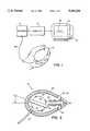
- FIG. 1is a simplified view of a graphics input system which uses the present invention
- FIG. 2is a diagramatic illustration in partial cross section of the present invention, showing the location of the internal components
- FIG. 3illustrates a side view of the upper and lower hemispherical members, particulary showing their interrelationship
- FIG. 4illustrates a top view of the upper hemispherical member, showing the relationship of the apertures to the X and Y axes;
- FIG. 5illustrates a bottom view of the lower hemispherical member, showing the relationship of the apertures to the X and Y axes;
- FIG. 6is a cross sectional view of the orientation sensor along the spherical housing X-axis shown in FIG. 4 and FIG. 5;
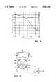
- FIG. 7Aillustrates an LED, showing in particular the displacement angle from the optical axis of the emitted beam
- FIG. 7Billustrates, graphically, the relationship between the photon intensity of the beam and displacement angle for the LED shown in FIG. 7A;
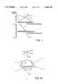
- FIGS. 8A, 8B, 8Cillustrate the functioning of a single LED/phototransistor pair at various angles of rotation
- FIG. 9illustrates, graphically, the relationship between the angle of rotation and the magnitude of the refracted signal for the LED/phototransistor pair shown in FIG. 8;
- FIG. 10illustrates the electrical function of a single axis of the present invention, showing in particular the analog circuitry associated with that axis;
- FIG. 11illustrates, graphically, the relationship between the angle of rotation of the spherical housing and the output of the differential amplifier shown in FIG. 10;
- FIG. 12illustrates the orientation of the present invention in the X and Y axes
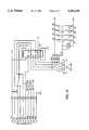
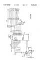
- FIG. 13illustrates the electrical circuitry of the computer input device of the present invention
- FIG. 14illustrates the electrical circuitry of the interface used with the present invention
- FIG. 15shows, in flow chart form, the microcontroller microprogram of the interface used with the present invention.
- FIG. 16illustrates an alternative embodiment of the present invention.
- FIG. 1illustrates a graphics display system which embodies the computer input device of the present invention.
- the systemincludes a computer input device 10, an interface 12, a computer 14, and a display terminal unit 16 having a display screen 18.
- the computer input device 10is a hand-held unit and requires no physical contact with a flat desktop to operate.
- the computer input device 10includes an orientation sensor which provides an electrical analog signal that is related to the angle of tilt of the sensor as determined in two axes. The user conveniently holds the device and, by changing orientation of the device by simple angular gestures, left-to-right, forward-to-back, or combinations of the two, the user effects a corresponding movement of a cursor displayed on the display screen 18.
- the computer input device 10further includes circuitry to digitize the analog signals generated by the orientation sensor for processing by the interface 12 and transmission to the computer 14.
- a cable 20carries digitized signals from the computer input device 10 to the interface 12.
- the interface 12contains a programmed microcontroller for receiving digitized signals from the computer input device 10 and translating those signals into control signals which can be interpreted by the computer 14, which in turn controls the display terminial unit 16.
- the interface 12is programmed to simulate the operation of a graphics input device, and provides a standard RS-232C output to a conventional digital computer 14. This specific circuitry will be discussed in more detail in connection with FIG. 14.
- the display screen 14is a standard cathode ray tube, but any conventional display types may be used, such as plasmas or liquid crystals.
- the computer input device 10simulates the functioning of a graphics input tablet.
- a usercan therefore make line drawings 22 on the display screen 18 as shown in FIG. 1.
- other devicesmay be easily simulated, such as conventional "mouse.” The manner in which the present invention operates will be discussed further in what follows.
- the computer input device 10includes a housing 24, preferably molded of durable plastic, which is compact in size.
- the housing 10is generally ovoid shaped to provide a comfortable grip to a user holding the computer input device 10 for prolonged time periods.
- the ovoid shapeis further advantageous for housing a spherical orientation sensor 25 while keeping the computer input device 10 desirably small.
- the gradual tapering of the front portion 26 of the housing 24provides a directional reference to the user for pointing at the display screen 18. It is understood, however, that housings having other shapes may also be desirable.
- a trigger switch 32is provided on the lower side of the housing 24 adjacent to the front portion 26. It is positioned so that it may be activated by the user's forefinger in operation of the computer input device 10.
- a subroutineis initiated in the interface 12 which reduces the sensitivity of the computer input device 10, making it possible for the user to make finer, more controlled movements of the cursor on the display screen 18.
- the switches 28, 30 and the trigger switch 32are all momentary contact microswitches, mechanically identical to those found in conventional "mouse" input devices.
- Two printed circuit boards 34, 36contain the electronic circuitry for the computer input device 10, the connection points for the switches 28, 30 and trigger switch 32, and interconnection wiring for the cable 20 which leads to the interface 12. For simplicity, the interconnection wiring is not shown in FIG. 2.
- the printed circuit boards 34, 36include analog circuitry for the operation of the orientation sensor 25 and digital circuitry for communication with the interface 12. The specific circuitry will be discussed further on.
- the cable 20exits the lower rear portion of the housing 24, so that it will cause minimum interference during operation of the computer input device 10.
- direct cablingis used in the preferred embodiment to keep the computer input device 10 inexpensive, it is within the scope of the present invention to link the computer input device 10 to the interface 12 by means of conventional miniature transmitter technology.
- the orientation sensor 25which is a major component of the present invention, will be described in considerable detail.
- the orientation sensor 25is fixedly mounted within the housing 24. As illustrated in FIG. 2, the orientation sensor 25 is mounted angularly forward. This angled mounting serves to improve the ergonomics of the computer input device 10. For a user holding the computer input device 10, the most comfortable holding position was found to be with the front portion 26 raised slightly. By mounting the orientation sensor 25 at the angle described, the orientation sensor 25 becomes level when the front portion 26 is raised to the desired position. The output voltage of the orientation sensor 25 and the resultant cursor motion on display screen 18 will then be null. This will be better appreciated by consideration of the structure of the orientation sensor 25 in the descriptions which follow.
- FIGS. 3 through 6illustrate the structure of the orientation sensor 25.
- the orientation sensor 25includes a spherical housing 38 having upper and lower hemispherical members 40, 42 which mate together to form a hollow spherical enclosure.
- the upper hemispherical member 40includes a circular ridge 44 and four apertures 46-52 which are spaced 45 degrees from the horizontal.
- the lower hemispherical member 42includes a circular collar 54 and a circular recess 56 therein for receiving the circular ridge 44 when the upper and lower hemispherical members 40, 42 are mated to form the completed spherical housing 38.
- the lower hemispherical memberincludes four apertures 58-62 which correspond to those in the upper hemispherical member 40. These apertures 58-64 are also spaced 45 degrees from the horizontal as shown in FIG. 3.
- the four apertures 46-52 in the upper hemispherical memberdefine X and Y axes as shown in FIG. 4, and the same is true for the apertures 58-64 in the lower hemispherical member 42 as shown in FIG. 5.
- the apertures associated with each axisare precisely aligned.
- the four apertures 46-52 in the upper hemispherical member 40receive light sources or LEDs and the four apertures 58-64 in the lower hemispherical member receive photosensors or phototransistors.
- the LEDs and phototransistorsare mounted with an adhesive which provides a liquid tight seal.
- FIG. 6presents a cross sectional view of the fully assembled orientation sensor 25 taken along the X axis shown in FIG. 4.
- Light emitting diodes 68, 70are shown mounted in apertures 46 and 50, and phototransistors 72, 74 are shown mounted in apertures 58 and 62.
- the spherical housing 38is advantageously fabricated from Noryl, a plastic which is opaque with a non-reflective matte finish. It is particularly important for the inner wall 74 of the spherical housing 38 to be generally non-reflective, or proper operation of the orientation sensor 25 could be affected by stray reflections.
- the LEDs 68, 70are directly opposed to the phototransistors 74, 72 along the diameter of the spherical housing 38. Therefore light emitted from each LED would normally pass through a center point of the spherical housing 38 and be received by the opposite phototransistor.
- the spherical housingcontains a transparent fluid 76 which refracts the light emitted in a manner which is central to the present invention.
- the transparent fluid 76has a desirable index of refraction and viscosity.
- the transparent fluid 76fills the sphere to precisely the one-half level within the spherical housing 38.
- the properties considered important in the selection of the transparent fluid 76are viscosity and index of refraction.
- the transparent fluid 76flows along the inner wall 74 of the spherical housing 38 to regain equilibrium.
- the rate of fluid movement and hence the response speed of the orientation sensor 25is related to the viscosity of the transparent fluid 76. Fluid having a low viscosity flows more readily than a fluid with a higher viscosity, which would translate into faster cursor movement on display screen 18. A higher viscosity fluid provides a damping effect.
- the LEDs 68, 70 and the phototransistors 74, 72are spectrally and mechanically matched.
- Type TIL39 light emitting diodes and Type TIL78 phototransistorsare used.
- FIG. 7A and FIG. 7Billustrates the typical optical parameters of the LEDs 68, 70 showing in particular how photon intensity varies with angular displacement from the optical axis of the device. It is significant to note that photon intensity follows a Gaussian-shaped curve. At an angle 20 degrees from the optical axis, photon intensity decreases to 50 percent of the maximum value at the optical axis.
- the phototransistors 74, 72have similar characteristics in the sensing of light.
- FIG. 8illustrates the functioning of a single LED/phototransistor pair at various angles of rotation with respect to the vertical axis 79.
- the LED 70 and photodetector 72are disposed on the same beam axis 80 which passes through the center point of the spherical housing 38.
- the beam axis 80is perpendicular to the surface of the transparent fluid 76 and the angle of refraction is zero.
- the light beamrepresented in the FIG. 8 as the region within the dotted lines, is refracted inwardly toward the phototransistor 72, producing a collimating effect. The maximum amount of light is received by the phototransistor 72.
- the spherical housing 38has been rotated 30 degrees from the vertical axis 79, and the light beam is refracted downwardly from the beam axis 80 which passes through the LED/phototransistor pair.
- the refracted signal detected by the phototransistor 72is decreased.
- FIG. 9plots the angle of rotation against the refracted signal, as detected by the phototransistor 72.
- the angle from the vertical axis 79 to the beam axis 80will increase, and the refraction angle of the light beam will also increase, though not to the same degree.
- the signal detected by the phototransistordecreases until the angle of rotation from the vertical axis 79 approaches 90 degrees, where the light beam passes from the LED 70 to the phototransistor 72 on the surface of the transparent fluid 76, and the signal intensity increases to maximum.
- FIG. 10illustrates one axis of the present invention, showing in particular the analog electrical circuitry associated with that axis.
- a single voltage source 81supplies the LEDs 68, 70, and the light intensity is balanced by means of individual potentiometers 82, 84.
- the outputs of the phototransistors 72, 74are applied to a differential amplifier 86.
- the LEDs 68, 70are 45 degrees above the surface of the transparent fluid 76, and the output of the differential amplifier 86 is zero because the output voltages of the phototransistors 72, 74 are balanced at 50 percent of their maximum value.
- the output voltage of the differential amplifier 86varies in the positive or negative direction with the magnitude indicating the angle of rotation.
- FIG. 11shows the relationship between the angle of rotation of the spherical housing 38 and the output of the differential amplifier 86.
- the orientation sensor 25detects rotation angles from zero to 45 degrees in either the negative or positive direction as defined in FIG. 10.
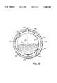
- FIG. 12depicts the orientation sensor 25 operating in two axes.
- the orientation sensor 25detects rotation in any direction from the vertical axis 79. Furthermore, there is no unwanted interaction between the X and Y axis. If rotation is solely in the direction of the X axis, for example, the Y axis output of the differential amplifier 86 will remain zero because both phototransistors 72, 74 will detect an equal decrease in light intensity.
- Each of the four LED's 66-69has an associated adjustment potentiometer 82-85, for adjustment of LED intensity.
- the LED's 66-69are independently adjustable to provide a means for calibrating the orientation sensor 25 at the time of manufacture and testing to overcome problems caused by tolerance variations in each LED/phototransistor pair.
- the LED's 66-69 and the matched phototransistor pairs 72-75provide input to a four-channel serial analog-to-digital converter 86.
- the IC chosenis a Texas Instruments type ADC0834.
- the analog-to-digital converteremploys a data comparator structure to differentially compare the input signals in pairs and output data bytes with eight-bit resolution which indicate the resultant magnitude and sign of the compared signals.
- Clock (CLK) and chip strobe (CS)are received from the interface 12 for scanning orientation sensor 25. Data is output serially on line DO in response to a chip strobe (CS).
- CLKclock
- CSchip strobe
- the SELECT and RETURN switches 28, 30 and the trigger switch 32are also scanned by the interface 12.
- FIG. 14illustrates the major circuitry of the interface 12.
- the microcontroller 90is a Motorola type 68701, which has a microprogram to calculate the X and Y positions of the orientation sensor 25, format the position data to simulate the operation of a graphics input device, and present the data to the computer 14.
- the microcontroller 90causes the microcontroller 90 to monitor computer input device 10 including the positions of the SELECT and RETURN switches 28, 30 (data FE), and the trigger switch 32 (slow motion). If the trigger switch 32 is not activated, the microcontroller reads the eight bit positive X-axis byte (FD) or, if zero, the negative X-axis position byte (FC) and stores the X position data as the most significant of 14 bits. Upon calculating X, the microprocessor 90 calculates the Y-axis positional data (FB & FA) the same way. The stored X and Y position words are then averaged with the present X an Y values, and the result is transmitted over an RS-232 link to the computer 14, along with the switch position data FE.
- FDeight bit positive X-axis byte
- FCnegative X-axis position byte
- a second subroutinecalculates the X-axis and Y-axis positional data the same as before, except the X and Y position data are stored as the most significant of 10 bits, instead of 14 bits. This has the effect of slowing down cursor movement on display screen 18.
- an operatorIn operation of computer input device 10, an operator, wishing to effect cursor movement on the display screen 18, engages the SELECT switch 28. The operator then tilts the computer input device, front-to-back or side-to-side corresponding to rotation toward the X-axis or Y-axis, shown particulary in FIG. 12.
- a forward tilting rotationcauses a downward movement of the cursor on display screen 18.
- a backward tilting rotationcauses an upward movement of the cursor.
- a rotation to the leftcauses a leftward movement of the cursor, and a rotation toward the right causes a rightward movement of the cursor.
- the speed of cursor movementcorresponds to the rotation angle of the computer input device 25. Should the operator wish to slow down movement of the cursor, to make more finely controlled movements, the operator engages the trigger switch 32. As long as the trigger switch is engaged, the cursor will move in apparent slow motion.
- a hollow transparent sphere 92is half-filled with transparent fluid 94.
- the hollow sphere 92in disposed within an optically opaque spherical enclosure comprising upper and lower hemispherical members 96, 98.
- the upper and lower hemispherical members 96, 98include support projections 100 for supporting the hollow sphere 92.
- At least one light source 102 and one optical detector 104are disposed in the upper and lower hemispherical members 96, 98 along an axis passing through the center of the transparent sphere 92.
- the light source 102 and the optical detector 104are in contact with the hollow sphere 92.
- An air gap 106separates the hollow sphere 92 from the upper and lower hemispherical members 96, 98.
Landscapes
- Engineering & Computer Science (AREA)
- General Engineering & Computer Science (AREA)
- Theoretical Computer Science (AREA)
- Human Computer Interaction (AREA)
- Physics & Mathematics (AREA)
- General Physics & Mathematics (AREA)
- Position Input By Displaying (AREA)
Abstract
Description
Claims (24)
Priority Applications (1)
| Application Number | Priority Date | Filing Date | Title |
|---|---|---|---|
| US08/128,043US5363120A (en) | 1987-10-14 | 1993-09-27 | Computer input device using orientation sensor |
Applications Claiming Priority (4)
| Application Number | Priority Date | Filing Date | Title |
|---|---|---|---|
| US10817687A | 1987-10-14 | 1987-10-14 | |
| US41889589A | 1989-10-04 | 1989-10-04 | |
| US71965891A | 1991-06-24 | 1991-06-24 | |
| US08/128,043US5363120A (en) | 1987-10-14 | 1993-09-27 | Computer input device using orientation sensor |
Related Parent Applications (1)
| Application Number | Title | Priority Date | Filing Date |
|---|---|---|---|
| US71965891AContinuation | 1987-10-14 | 1991-06-24 |
Publications (1)
| Publication Number | Publication Date |
|---|---|
| US5363120Atrue US5363120A (en) | 1994-11-08 |
Family
ID=27380439
Family Applications (1)
| Application Number | Title | Priority Date | Filing Date |
|---|---|---|---|
| US08/128,043Expired - LifetimeUS5363120A (en) | 1987-10-14 | 1993-09-27 | Computer input device using orientation sensor |
Country Status (1)
| Country | Link |
|---|---|
| US (1) | US5363120A (en) |
Cited By (73)
| Publication number | Priority date | Publication date | Assignee | Title |
|---|---|---|---|---|
| US5602569A (en)* | 1994-04-28 | 1997-02-11 | Nintendo Co., Ltd. | Controller for image processing apparatus |
| US5649861A (en)* | 1993-08-25 | 1997-07-22 | Sega Enterprises, Ltd. | Game device for displaying game input operations on the display |
| US5650608A (en)* | 1991-12-05 | 1997-07-22 | Tv Interactive Data Corporation | Method and apparatus for generating ratiometric control signals |
| US5734371A (en)* | 1994-12-19 | 1998-03-31 | Lucent Technologies Inc. | Interactive pointing device |
| US5748494A (en)* | 1996-05-22 | 1998-05-05 | Ko; Wen-San | Method and arrangement for resolution enhancement |
| US5764164A (en)* | 1997-02-07 | 1998-06-09 | Reality Quest Corp. | Ergonomic hand-attachable controller |
| US5786804A (en)* | 1995-10-06 | 1998-07-28 | Hewlett-Packard Company | Method and system for tracking attitude |
| US5796387A (en)* | 1994-08-16 | 1998-08-18 | Smith Engineering | Positioning system using infrared radiation |
| US5794355A (en)* | 1996-06-03 | 1998-08-18 | Gateway 2000, Inc. | Rotationally actuated position sensor |
| US5796354A (en)* | 1997-02-07 | 1998-08-18 | Reality Quest Corp. | Hand-attachable controller with direction sensing |
| US5818037A (en)* | 1996-04-09 | 1998-10-06 | Tv Interactive Data Corporation | Controller using a flexible element to vary light transferred to a photosensitive element |
| US5847694A (en)* | 1991-12-05 | 1998-12-08 | Tv Interactive Data Corporation | Apparatus for generating a signal indicative of the position of a movable element in the apparatus |
| US5898421A (en)* | 1990-03-21 | 1999-04-27 | Gyration, Inc. | Gyroscopic pointer and method |
| US5923318A (en)* | 1996-04-12 | 1999-07-13 | Zhai; Shumin | Finger manipulatable 6 degree-of-freedom input device |
| US6028271A (en) | 1992-06-08 | 2000-02-22 | Synaptics, Inc. | Object position detector with edge motion feature and gesture recognition |
| US6072467A (en)* | 1996-05-03 | 2000-06-06 | Mitsubishi Electric Information Technology Center America, Inc. (Ita) | Continuously variable control of animated on-screen characters |
| US6147677A (en)* | 1998-03-10 | 2000-11-14 | Universal Electronics Inc. | Sensing and control devices using pressure sensitive resistive elements |
| US6239389B1 (en) | 1992-06-08 | 2001-05-29 | Synaptics, Inc. | Object position detection system and method |
| US6256016B1 (en)* | 1997-06-05 | 2001-07-03 | Logitech, Inc. | Optical detection system, device, and method utilizing optical matching |
| US6317118B1 (en)* | 1997-11-07 | 2001-11-13 | Seiko Epson Corporation | Remote coordinate input device and remote coordinate input method |
| WO2002031788A1 (en)* | 2000-09-22 | 2002-04-18 | Motorola Inc., A Corporation Of The State Of Delaware | Method and apparatus for motion activated control of an electronic device |
| US6375572B1 (en) | 1999-10-04 | 2002-04-23 | Nintendo Co., Ltd. | Portable game apparatus with acceleration sensor and information storage medium storing a game progam |
| US6380931B1 (en)* | 1992-06-08 | 2002-04-30 | Synaptics Incorporated | Object position detector with edge motion feature and gesture recognition |
| US6486873B1 (en) | 2000-04-06 | 2002-11-26 | Microsoft Corporation | Illuminated computer input device |
| US20030107551A1 (en)* | 2001-12-10 | 2003-06-12 | Dunker Garrett Storm | Tilt input device |
| US6585593B1 (en) | 1993-08-25 | 2003-07-01 | Sega Enterprises, Ltd. | Game device for displaying game input operations on the display |
| US20040029640A1 (en)* | 1999-10-04 | 2004-02-12 | Nintendo Co., Ltd. | Game system and game information storage medium used for same |
| EP1396780A1 (en)* | 2002-09-03 | 2004-03-10 | Hewlett-Packard Company | Context input device |
| US20040090423A1 (en)* | 1998-02-27 | 2004-05-13 | Logitech Europe S.A. | Remote controlled video display GUI using 2-directional pointing |
| US20050026689A1 (en)* | 2000-07-21 | 2005-02-03 | Marks Richard L. | System and method for object tracking |
| US20050078086A1 (en)* | 2003-10-09 | 2005-04-14 | Grams Richard E. | Method and apparatus for controlled display |
| US6908386B2 (en) | 2002-05-17 | 2005-06-21 | Nintendo Co., Ltd. | Game device changing sound and an image in accordance with a tilt operation |
| US20050179662A1 (en)* | 1995-10-06 | 2005-08-18 | Agilent Technologies, Inc. | "Seeing eye" mouse for a computer system |
| US20050285948A1 (en)* | 2004-06-22 | 2005-12-29 | Harvey Weinberg | System and method for processing a digital camera image |
| US20060187214A1 (en)* | 1992-06-08 | 2006-08-24 | Synaptics, Inc, A California Corporation | Object position detector with edge motion feature and gesture recognition |
| US20060204232A1 (en)* | 2005-02-01 | 2006-09-14 | Harvey Weinberg | Camera with acceleration sensor |
| US20090033630A1 (en)* | 2004-06-04 | 2009-02-05 | Koninklijke Philips Electronics, N.V. | hand-held device for content navigation by a user |
| US20090295713A1 (en)* | 2008-05-30 | 2009-12-03 | Julien Piot | Pointing device with improved cursor control in-air and allowing multiple modes of operations |
| US20100009746A1 (en)* | 2008-07-14 | 2010-01-14 | Raymond Jesse B | Music video game with virtual drums |
| US7696980B1 (en) | 2006-06-16 | 2010-04-13 | Logitech Europe S.A. | Pointing device for use in air with improved cursor control and battery life |
| US7716008B2 (en) | 2007-01-19 | 2010-05-11 | Nintendo Co., Ltd. | Acceleration data processing program, and storage medium, and acceleration data processing apparatus for use with the same |
| US7774155B2 (en) | 2006-03-10 | 2010-08-10 | Nintendo Co., Ltd. | Accelerometer-based controller |
| US7850527B2 (en) | 2000-02-22 | 2010-12-14 | Creative Kingdoms, Llc | Magic-themed adventure game |
| US7896742B2 (en) | 2000-02-22 | 2011-03-01 | Creative Kingdoms, Llc | Apparatus and methods for providing interactive entertainment |
| US7927216B2 (en) | 2005-09-15 | 2011-04-19 | Nintendo Co., Ltd. | Video game system with wireless modular handheld controller |
| US20110172016A1 (en)* | 2005-08-22 | 2011-07-14 | Nintendo Co., Ltd. | Game operating device |
| US8013840B1 (en) | 2000-04-06 | 2011-09-06 | Microsoft Corporation | User notification system with an illuminated computer input device |
| US8089458B2 (en) | 2000-02-22 | 2012-01-03 | Creative Kingdoms, Llc | Toy devices and methods for providing an interactive play experience |
| US8133115B2 (en) | 2003-10-22 | 2012-03-13 | Sony Computer Entertainment America Llc | System and method for recording and displaying a graphical path in a video game |
| US8157651B2 (en) | 2005-09-12 | 2012-04-17 | Nintendo Co., Ltd. | Information processing program |
| US8204272B2 (en) | 2006-05-04 | 2012-06-19 | Sony Computer Entertainment Inc. | Lighting control of a user environment via a display device |
| US8226493B2 (en) | 2002-08-01 | 2012-07-24 | Creative Kingdoms, Llc | Interactive play devices for water play attractions |
| US8243089B2 (en) | 2006-05-04 | 2012-08-14 | Sony Computer Entertainment Inc. | Implementing lighting control of a user environment |
| US8267786B2 (en) | 2005-08-24 | 2012-09-18 | Nintendo Co., Ltd. | Game controller and game system |
| US8284310B2 (en) | 2005-06-22 | 2012-10-09 | Sony Computer Entertainment America Llc | Delay matching in audio/video systems |
| US8289325B2 (en) | 2004-10-06 | 2012-10-16 | Sony Computer Entertainment America Llc | Multi-pass shading |
| US8308563B2 (en) | 2005-08-30 | 2012-11-13 | Nintendo Co., Ltd. | Game system and storage medium having game program stored thereon |
| US8313379B2 (en) | 2005-08-22 | 2012-11-20 | Nintendo Co., Ltd. | Video game system with wireless modular handheld controller |
| US20130016041A1 (en)* | 2011-07-13 | 2013-01-17 | Kuo-Ching Chiang | High Resolution Mouse |
| US8409003B2 (en) | 2005-08-24 | 2013-04-02 | Nintendo Co., Ltd. | Game controller and game system |
| US8608535B2 (en) | 2002-04-05 | 2013-12-17 | Mq Gaming, Llc | Systems and methods for providing an interactive game |
| US8702515B2 (en) | 2002-04-05 | 2014-04-22 | Mq Gaming, Llc | Multi-platform gaming system using RFID-tagged toys |
| US8753165B2 (en) | 2000-10-20 | 2014-06-17 | Mq Gaming, Llc | Wireless toy systems and methods for interactive entertainment |
| US8758136B2 (en) | 1999-02-26 | 2014-06-24 | Mq Gaming, Llc | Multi-platform gaming systems and methods |
| US9092071B2 (en) | 2008-02-13 | 2015-07-28 | Logitech Europe S.A. | Control device with an accelerometer system |
| US9342817B2 (en) | 2011-07-07 | 2016-05-17 | Sony Interactive Entertainment LLC | Auto-creating groups for sharing photos |
| US20160231819A1 (en)* | 2015-02-11 | 2016-08-11 | Avaya Inc. | Wearable system input device |
| US9446319B2 (en) | 2003-03-25 | 2016-09-20 | Mq Gaming, Llc | Interactive gaming toy |
| US10254930B2 (en) | 2000-04-03 | 2019-04-09 | Google Llc | Indicating potential focus in a user interface |
| US10515561B1 (en) | 2013-03-15 | 2019-12-24 | Study Social, Inc. | Video presentation, digital compositing, and streaming techniques implemented via a computer network |
| US10786736B2 (en) | 2010-05-11 | 2020-09-29 | Sony Interactive Entertainment LLC | Placement of user information in a game space |
| US11402927B2 (en) | 2004-05-28 | 2022-08-02 | UltimatePointer, L.L.C. | Pointing device |
| US11841997B2 (en) | 2005-07-13 | 2023-12-12 | UltimatePointer, L.L.C. | Apparatus for controlling contents of a computer-generated image using 3D measurements |
Citations (22)
| Publication number | Priority date | Publication date | Assignee | Title |
|---|---|---|---|---|
| US3464276A (en)* | 1965-06-01 | 1969-09-02 | Edward E Leibert | Inclinometer or accelerometer |
| CA892801A (en)* | 1972-02-08 | Amf Incorporated | Position control lever device | |
| US3643148A (en)* | 1970-04-16 | 1972-02-15 | Edo Corp | Ball tracker assembly |
| US4024823A (en)* | 1974-06-24 | 1977-05-24 | The United States Of America As Represented By The Secretary Of The Navy | Automatic blade angle controller system |
| CA1039406A (en)* | 1974-12-12 | 1978-09-26 | Robert E. Elas | Well surveying apparatus |
| AU3353778A (en)* | 1977-03-03 | 1979-08-30 | ||
| US4209255A (en)* | 1979-03-30 | 1980-06-24 | United Technologies Corporation | Single source aiming point locator |
| CA1081342A (en)* | 1978-10-18 | 1980-07-08 | Atomic Energy Of Canada Limited - Energie Atomique Du Canada, Limitee | Three dimensional strain gage transducer |
| US4214485A (en)* | 1978-06-07 | 1980-07-29 | Paul J. Berger | Electro-mechanical transducer |
| US4307516A (en)* | 1980-02-07 | 1981-12-29 | The United States Of America As Represented By The Secretary Of The Army | Directional two-axis differential optical inclinometer |
| US4445011A (en)* | 1981-10-13 | 1984-04-24 | Hansen Ronald E | Freestanding multidirectional electrical control device |
| US4450325A (en)* | 1981-10-08 | 1984-05-22 | Luque Tom R | Electro-mechanical hand controller |
| JPS6031637A (en)* | 1983-08-01 | 1985-02-18 | Fuji Xerox Co Ltd | Optical mouth |
| US4503299A (en)* | 1981-08-07 | 1985-03-05 | Thomson-Brandt | Control-lever for a game |
| US4524348A (en)* | 1983-09-26 | 1985-06-18 | Lefkowitz Leonard R | Control interface |
| US4550250A (en)* | 1983-11-14 | 1985-10-29 | Hei, Inc. | Cordless digital graphics input device |
| US4565999A (en)* | 1983-04-01 | 1986-01-21 | Prime Computer, Inc. | Light pencil |
| US4567479A (en)* | 1982-12-23 | 1986-01-28 | Boyd Barry S | Directional controller apparatus for a video or computer input |
| US4590680A (en)* | 1984-06-13 | 1986-05-27 | Technical Designs Incorporated | Electronic inclination sensing device |
| US4698626A (en)* | 1984-06-02 | 1987-10-06 | Brother Kogyo Kabushiki Kaisha | Coordinate-data input device for CRT display having cursor travel control means |
| US4754268A (en)* | 1984-10-13 | 1988-06-28 | Mitsuboshi Belting Ltd. | Wireless mouse apparatus |
| US4862172A (en)* | 1987-09-14 | 1989-08-29 | Texas Scottish Rite Hospital For Crippled Children | Computer control apparatus including a gravity referenced inclinometer |
- 1993
- 1993-09-27USUS08/128,043patent/US5363120A/ennot_activeExpired - Lifetime
Patent Citations (22)
| Publication number | Priority date | Publication date | Assignee | Title |
|---|---|---|---|---|
| CA892801A (en)* | 1972-02-08 | Amf Incorporated | Position control lever device | |
| US3464276A (en)* | 1965-06-01 | 1969-09-02 | Edward E Leibert | Inclinometer or accelerometer |
| US3643148A (en)* | 1970-04-16 | 1972-02-15 | Edo Corp | Ball tracker assembly |
| US4024823A (en)* | 1974-06-24 | 1977-05-24 | The United States Of America As Represented By The Secretary Of The Navy | Automatic blade angle controller system |
| CA1039406A (en)* | 1974-12-12 | 1978-09-26 | Robert E. Elas | Well surveying apparatus |
| AU3353778A (en)* | 1977-03-03 | 1979-08-30 | ||
| US4214485A (en)* | 1978-06-07 | 1980-07-29 | Paul J. Berger | Electro-mechanical transducer |
| CA1081342A (en)* | 1978-10-18 | 1980-07-08 | Atomic Energy Of Canada Limited - Energie Atomique Du Canada, Limitee | Three dimensional strain gage transducer |
| US4209255A (en)* | 1979-03-30 | 1980-06-24 | United Technologies Corporation | Single source aiming point locator |
| US4307516A (en)* | 1980-02-07 | 1981-12-29 | The United States Of America As Represented By The Secretary Of The Army | Directional two-axis differential optical inclinometer |
| US4503299A (en)* | 1981-08-07 | 1985-03-05 | Thomson-Brandt | Control-lever for a game |
| US4450325A (en)* | 1981-10-08 | 1984-05-22 | Luque Tom R | Electro-mechanical hand controller |
| US4445011A (en)* | 1981-10-13 | 1984-04-24 | Hansen Ronald E | Freestanding multidirectional electrical control device |
| US4567479A (en)* | 1982-12-23 | 1986-01-28 | Boyd Barry S | Directional controller apparatus for a video or computer input |
| US4565999A (en)* | 1983-04-01 | 1986-01-21 | Prime Computer, Inc. | Light pencil |
| JPS6031637A (en)* | 1983-08-01 | 1985-02-18 | Fuji Xerox Co Ltd | Optical mouth |
| US4524348A (en)* | 1983-09-26 | 1985-06-18 | Lefkowitz Leonard R | Control interface |
| US4550250A (en)* | 1983-11-14 | 1985-10-29 | Hei, Inc. | Cordless digital graphics input device |
| US4698626A (en)* | 1984-06-02 | 1987-10-06 | Brother Kogyo Kabushiki Kaisha | Coordinate-data input device for CRT display having cursor travel control means |
| US4590680A (en)* | 1984-06-13 | 1986-05-27 | Technical Designs Incorporated | Electronic inclination sensing device |
| US4754268A (en)* | 1984-10-13 | 1988-06-28 | Mitsuboshi Belting Ltd. | Wireless mouse apparatus |
| US4862172A (en)* | 1987-09-14 | 1989-08-29 | Texas Scottish Rite Hospital For Crippled Children | Computer control apparatus including a gravity referenced inclinometer |
Cited By (199)
| Publication number | Priority date | Publication date | Assignee | Title |
|---|---|---|---|---|
| USRE41520E1 (en) | 1990-03-21 | 2010-08-17 | Thomson Licensing | Gyroscopic pointer and method |
| US5898421A (en)* | 1990-03-21 | 1999-04-27 | Gyration, Inc. | Gyroscopic pointer and method |
| US5847694A (en)* | 1991-12-05 | 1998-12-08 | Tv Interactive Data Corporation | Apparatus for generating a signal indicative of the position of a movable element in the apparatus |
| US5650608A (en)* | 1991-12-05 | 1997-07-22 | Tv Interactive Data Corporation | Method and apparatus for generating ratiometric control signals |
| US5973313A (en)* | 1991-12-05 | 1999-10-26 | Tv Interactive Data Corporation | Method and apparatus for generating ratiometric control signals |
| US6414671B1 (en)* | 1992-06-08 | 2002-07-02 | Synaptics Incorporated | Object position detector with edge motion feature and gesture recognition |
| US6610936B2 (en)* | 1992-06-08 | 2003-08-26 | Synaptics, Inc. | Object position detector with edge motion feature and gesture recognition |
| US20060187214A1 (en)* | 1992-06-08 | 2006-08-24 | Synaptics, Inc, A California Corporation | Object position detector with edge motion feature and gesture recognition |
| US20060092142A1 (en)* | 1992-06-08 | 2006-05-04 | Synaptics, Inc., A California Corporation | Object position detector with edge motion feature and gesture recognition |
| US6750852B2 (en) | 1992-06-08 | 2004-06-15 | Synaptics, Inc. | Object position detector with edge motion feature and gesture recognition |
| US7450113B2 (en) | 1992-06-08 | 2008-11-11 | Synaptics Incorporated | Object position detector with edge motion feature and gesture recognition |
| US7532205B2 (en) | 1992-06-08 | 2009-05-12 | Synaptics, Inc. | Object position detector with edge motion feature and gesture recognition |
| US6380931B1 (en)* | 1992-06-08 | 2002-04-30 | Synaptics Incorporated | Object position detector with edge motion feature and gesture recognition |
| US6239389B1 (en) | 1992-06-08 | 2001-05-29 | Synaptics, Inc. | Object position detection system and method |
| US7109978B2 (en) | 1992-06-08 | 2006-09-19 | Synaptics, Inc. | Object position detector with edge motion feature and gesture recognition |
| US6028271A (en) | 1992-06-08 | 2000-02-22 | Synaptics, Inc. | Object position detector with edge motion feature and gesture recognition |
| US6585593B1 (en) | 1993-08-25 | 2003-07-01 | Sega Enterprises, Ltd. | Game device for displaying game input operations on the display |
| US5649861A (en)* | 1993-08-25 | 1997-07-22 | Sega Enterprises, Ltd. | Game device for displaying game input operations on the display |
| US6592455B1 (en)* | 1993-08-25 | 2003-07-15 | Sega Enterprises, Ltd. | Game device for displaying game input operations on the display |
| US5602569A (en)* | 1994-04-28 | 1997-02-11 | Nintendo Co., Ltd. | Controller for image processing apparatus |
| US6567071B1 (en)* | 1994-08-16 | 2003-05-20 | Kenneth J. Curran | Postitioning system using infrared radiation |
| US5796387A (en)* | 1994-08-16 | 1998-08-18 | Smith Engineering | Positioning system using infrared radiation |
| US5734371A (en)* | 1994-12-19 | 1998-03-31 | Lucent Technologies Inc. | Interactive pointing device |
| US7652661B2 (en) | 1995-10-06 | 2010-01-26 | Avago Technologies Ecbu Ip (Singapore) Pte. Ltd. | “Seeing eye” mouse for computer system |
| US20050231483A1 (en)* | 1995-10-06 | 2005-10-20 | Agilent Technologies, Inc. | Method of operating an optical mouse |
| US5786804A (en)* | 1995-10-06 | 1998-07-28 | Hewlett-Packard Company | Method and system for tracking attitude |
| US7808485B2 (en) | 1995-10-06 | 2010-10-05 | Avago Technologies Ecbu Ip (Singapore) Pte. Ltd. | Method of operating an optical mouse |
| US7907120B2 (en) | 1995-10-06 | 2011-03-15 | Avago Technologies Ecbu Ip (Singapore) Pte. Ltd. | Optical mouse with uniform level detection method |
| US7791590B1 (en) | 1995-10-06 | 2010-09-07 | Avago Technologies Ecbu Ip (Singapore) Pte. Ltd. | Optical mouse with uniform level detection |
| US7800585B2 (en) | 1995-10-06 | 2010-09-21 | Avago Technologies Ecbu Ip (Singapore) Pte. Ltd. | Method of operating an optical mouse |
| US20060139332A9 (en)* | 1995-10-06 | 2006-06-29 | Agilent Technologies, Inc. | "Seeing eye" mouse for a computer system |
| US20050231484A1 (en)* | 1995-10-06 | 2005-10-20 | Agilent Technologies, Inc. | Optical mouse with uniform level detection method |
| US20050179662A1 (en)* | 1995-10-06 | 2005-08-18 | Agilent Technologies, Inc. | "Seeing eye" mouse for a computer system |
| US8212778B2 (en) | 1995-10-06 | 2012-07-03 | Avago Technologies Ecbu Ip (Singapore) Pte. Ltd. | Imaging and navigation arrangement for controlling a cursor |
| US7643007B2 (en) | 1995-10-06 | 2010-01-05 | Avago Technologies Ecbu Ip (Singapore) Pte. Ltd. | Method of operating an optical mouse |
| US8350812B2 (en) | 1995-10-06 | 2013-01-08 | Pixart Imaging Inc. | Method and arrangement for tracking movement relative to a surface |
| US20070103439A1 (en)* | 1995-10-06 | 2007-05-10 | Avago Technologies, Ltd. | Method of operating an optical mouse |
| US20080048983A1 (en)* | 1995-10-06 | 2008-02-28 | Gordon Gary B | Method of operating an optical mouse |
| USRE40410E1 (en) | 1995-10-06 | 2008-07-01 | Avago Technologies Ecbu Ip Pte Ltd | Method and system for tracking attitude |
| US20080055243A1 (en)* | 1995-10-06 | 2008-03-06 | Gordon Gary B | Method of operating an optical mouse |
| US5818037A (en)* | 1996-04-09 | 1998-10-06 | Tv Interactive Data Corporation | Controller using a flexible element to vary light transferred to a photosensitive element |
| US5923318A (en)* | 1996-04-12 | 1999-07-13 | Zhai; Shumin | Finger manipulatable 6 degree-of-freedom input device |
| US6072467A (en)* | 1996-05-03 | 2000-06-06 | Mitsubishi Electric Information Technology Center America, Inc. (Ita) | Continuously variable control of animated on-screen characters |
| US5748494A (en)* | 1996-05-22 | 1998-05-05 | Ko; Wen-San | Method and arrangement for resolution enhancement |
| US5794355A (en)* | 1996-06-03 | 1998-08-18 | Gateway 2000, Inc. | Rotationally actuated position sensor |
| US5764164A (en)* | 1997-02-07 | 1998-06-09 | Reality Quest Corp. | Ergonomic hand-attachable controller |
| US5796354A (en)* | 1997-02-07 | 1998-08-18 | Reality Quest Corp. | Hand-attachable controller with direction sensing |
| US6256016B1 (en)* | 1997-06-05 | 2001-07-03 | Logitech, Inc. | Optical detection system, device, and method utilizing optical matching |
| US6587092B2 (en) | 1997-11-07 | 2003-07-01 | Seiko Epson Corporation | Remote coordinate input device and remote coordinate input method |
| US6317118B1 (en)* | 1997-11-07 | 2001-11-13 | Seiko Epson Corporation | Remote coordinate input device and remote coordinate input method |
| US20040090423A1 (en)* | 1998-02-27 | 2004-05-13 | Logitech Europe S.A. | Remote controlled video display GUI using 2-directional pointing |
| US6147677A (en)* | 1998-03-10 | 2000-11-14 | Universal Electronics Inc. | Sensing and control devices using pressure sensitive resistive elements |
| US8758136B2 (en) | 1999-02-26 | 2014-06-24 | Mq Gaming, Llc | Multi-platform gaming systems and methods |
| US8888576B2 (en) | 1999-02-26 | 2014-11-18 | Mq Gaming, Llc | Multi-media interactive play system |
| US9731194B2 (en) | 1999-02-26 | 2017-08-15 | Mq Gaming, Llc | Multi-platform gaming systems and methods |
| US10300374B2 (en) | 1999-02-26 | 2019-05-28 | Mq Gaming, Llc | Multi-platform gaming systems and methods |
| US9861887B1 (en) | 1999-02-26 | 2018-01-09 | Mq Gaming, Llc | Multi-platform gaming systems and methods |
| US9186585B2 (en) | 1999-02-26 | 2015-11-17 | Mq Gaming, Llc | Multi-platform gaming systems and methods |
| US9468854B2 (en) | 1999-02-26 | 2016-10-18 | Mq Gaming, Llc | Multi-platform gaming systems and methods |
| US9205332B2 (en) | 1999-10-04 | 2015-12-08 | Nintendo Co., Ltd. | Game system and game information storage medium used for same |
| US6375572B1 (en) | 1999-10-04 | 2002-04-23 | Nintendo Co., Ltd. | Portable game apparatus with acceleration sensor and information storage medium storing a game progam |
| US7601066B1 (en) | 1999-10-04 | 2009-10-13 | Nintendo Co., Ltd. | Game system and game information storage medium used for same |
| US9205331B2 (en) | 1999-10-04 | 2015-12-08 | Nintendo Co., Ltd. | Mobile wireless handset and system including mobile wireless handset |
| US20090325698A1 (en)* | 1999-10-04 | 2009-12-31 | Nintendo Co., Ltd. | Game system and game information storage medium used for same |
| US20040029640A1 (en)* | 1999-10-04 | 2004-02-12 | Nintendo Co., Ltd. | Game system and game information storage medium used for same |
| US10046231B2 (en) | 1999-10-04 | 2018-08-14 | Nintendo Co., Ltd. | Game system and game information storage medium used for same |
| US6641482B2 (en) | 1999-10-04 | 2003-11-04 | Nintendo Co., Ltd. | Portable game apparatus with acceleration sensor and information storage medium storing a game program |
| US9579565B2 (en) | 1999-10-04 | 2017-02-28 | Nintendo Co., Ltd. | Game system and game information storage medium used for same |
| US9138645B2 (en) | 1999-10-04 | 2015-09-22 | Nintendo Co., Ltd. | Game system and game information storage medium used for same |
| US20070178974A1 (en)* | 1999-10-04 | 2007-08-02 | Nintendo Co., Ltd. | Game system and game information storage medium used for same |
| US7223173B2 (en) | 1999-10-04 | 2007-05-29 | Nintendo Co., Ltd. | Game system and game information storage medium used for same |
| US8562402B2 (en) | 1999-10-04 | 2013-10-22 | Nintendo Co., Ltd. | Game system and game information storage medium used for same |
| US9579568B2 (en) | 2000-02-22 | 2017-02-28 | Mq Gaming, Llc | Dual-range wireless interactive entertainment device |
| US8491389B2 (en) | 2000-02-22 | 2013-07-23 | Creative Kingdoms, Llc. | Motion-sensitive input device and interactive gaming system |
| US8814688B2 (en) | 2000-02-22 | 2014-08-26 | Creative Kingdoms, Llc | Customizable toy for playing a wireless interactive game having both physical and virtual elements |
| US7850527B2 (en) | 2000-02-22 | 2010-12-14 | Creative Kingdoms, Llc | Magic-themed adventure game |
| US7896742B2 (en) | 2000-02-22 | 2011-03-01 | Creative Kingdoms, Llc | Apparatus and methods for providing interactive entertainment |
| US8790180B2 (en) | 2000-02-22 | 2014-07-29 | Creative Kingdoms, Llc | Interactive game and associated wireless toy |
| US8708821B2 (en) | 2000-02-22 | 2014-04-29 | Creative Kingdoms, Llc | Systems and methods for providing interactive game play |
| US9713766B2 (en) | 2000-02-22 | 2017-07-25 | Mq Gaming, Llc | Dual-range wireless interactive entertainment device |
| US8915785B2 (en) | 2000-02-22 | 2014-12-23 | Creative Kingdoms, Llc | Interactive entertainment system |
| US8089458B2 (en) | 2000-02-22 | 2012-01-03 | Creative Kingdoms, Llc | Toy devices and methods for providing an interactive play experience |
| US9814973B2 (en) | 2000-02-22 | 2017-11-14 | Mq Gaming, Llc | Interactive entertainment system |
| US8686579B2 (en) | 2000-02-22 | 2014-04-01 | Creative Kingdoms, Llc | Dual-range wireless controller |
| US8164567B1 (en) | 2000-02-22 | 2012-04-24 | Creative Kingdoms, Llc | Motion-sensitive game controller with optional display screen |
| US8169406B2 (en) | 2000-02-22 | 2012-05-01 | Creative Kingdoms, Llc | Motion-sensitive wand controller for a game |
| US8184097B1 (en) | 2000-02-22 | 2012-05-22 | Creative Kingdoms, Llc | Interactive gaming system and method using motion-sensitive input device |
| US10307671B2 (en) | 2000-02-22 | 2019-06-04 | Mq Gaming, Llc | Interactive entertainment system |
| US8475275B2 (en) | 2000-02-22 | 2013-07-02 | Creative Kingdoms, Llc | Interactive toys and games connecting physical and virtual play environments |
| US9474962B2 (en) | 2000-02-22 | 2016-10-25 | Mq Gaming, Llc | Interactive entertainment system |
| US9149717B2 (en) | 2000-02-22 | 2015-10-06 | Mq Gaming, Llc | Dual-range wireless interactive entertainment device |
| US8368648B2 (en) | 2000-02-22 | 2013-02-05 | Creative Kingdoms, Llc | Portable interactive toy with radio frequency tracking device |
| US10188953B2 (en) | 2000-02-22 | 2019-01-29 | Mq Gaming, Llc | Dual-range wireless interactive entertainment device |
| US10895965B2 (en) | 2000-04-03 | 2021-01-19 | Google Llc | Indicating potential focus in a user interface |
| US10254930B2 (en) | 2000-04-03 | 2019-04-09 | Google Llc | Indicating potential focus in a user interface |
| US8279177B2 (en) | 2000-04-06 | 2012-10-02 | Microsoft Corporation | User notification system with an illuminated computer input device |
| US6486873B1 (en) | 2000-04-06 | 2002-11-26 | Microsoft Corporation | Illuminated computer input device |
| US8013840B1 (en) | 2000-04-06 | 2011-09-06 | Microsoft Corporation | User notification system with an illuminated computer input device |
| US8629838B2 (en) | 2000-04-06 | 2014-01-14 | Microsoft Corporation | User notification system with an illuminated computer input device |
| US7113193B2 (en) | 2000-07-21 | 2006-09-26 | Sony Computer Entertainment Inc. | Method for color transition detection |
| US20050026689A1 (en)* | 2000-07-21 | 2005-02-03 | Marks Richard L. | System and method for object tracking |
| WO2002031788A1 (en)* | 2000-09-22 | 2002-04-18 | Motorola Inc., A Corporation Of The State Of Delaware | Method and apparatus for motion activated control of an electronic device |
| US6529144B1 (en)* | 2000-09-22 | 2003-03-04 | Motorola Inc. | Method and apparatus for motion activated control of an electronic device |
| US9931578B2 (en) | 2000-10-20 | 2018-04-03 | Mq Gaming, Llc | Toy incorporating RFID tag |
| US10307683B2 (en) | 2000-10-20 | 2019-06-04 | Mq Gaming, Llc | Toy incorporating RFID tag |
| US9320976B2 (en) | 2000-10-20 | 2016-04-26 | Mq Gaming, Llc | Wireless toy systems and methods for interactive entertainment |
| US8753165B2 (en) | 2000-10-20 | 2014-06-17 | Mq Gaming, Llc | Wireless toy systems and methods for interactive entertainment |
| US9480929B2 (en) | 2000-10-20 | 2016-11-01 | Mq Gaming, Llc | Toy incorporating RFID tag |
| US8961260B2 (en) | 2000-10-20 | 2015-02-24 | Mq Gaming, Llc | Toy incorporating RFID tracking device |
| US8913011B2 (en) | 2001-02-22 | 2014-12-16 | Creative Kingdoms, Llc | Wireless entertainment device, system, and method |
| US8248367B1 (en) | 2001-02-22 | 2012-08-21 | Creative Kingdoms, Llc | Wireless gaming system combining both physical and virtual play elements |
| US10758818B2 (en) | 2001-02-22 | 2020-09-01 | Mq Gaming, Llc | Wireless entertainment device, system, and method |
| US8384668B2 (en) | 2001-02-22 | 2013-02-26 | Creative Kingdoms, Llc | Portable gaming device and gaming system combining both physical and virtual play elements |
| US8711094B2 (en) | 2001-02-22 | 2014-04-29 | Creative Kingdoms, Llc | Portable gaming device and gaming system combining both physical and virtual play elements |
| US9737797B2 (en) | 2001-02-22 | 2017-08-22 | Mq Gaming, Llc | Wireless entertainment device, system, and method |
| US10179283B2 (en) | 2001-02-22 | 2019-01-15 | Mq Gaming, Llc | Wireless entertainment device, system, and method |
| US9162148B2 (en) | 2001-02-22 | 2015-10-20 | Mq Gaming, Llc | Wireless entertainment device, system, and method |
| US9393491B2 (en) | 2001-02-22 | 2016-07-19 | Mq Gaming, Llc | Wireless entertainment device, system, and method |
| US20030107551A1 (en)* | 2001-12-10 | 2003-06-12 | Dunker Garrett Storm | Tilt input device |
| US9463380B2 (en) | 2002-04-05 | 2016-10-11 | Mq Gaming, Llc | System and method for playing an interactive game |
| US9616334B2 (en) | 2002-04-05 | 2017-04-11 | Mq Gaming, Llc | Multi-platform gaming system using RFID-tagged toys |
| US10010790B2 (en) | 2002-04-05 | 2018-07-03 | Mq Gaming, Llc | System and method for playing an interactive game |
| US8827810B2 (en) | 2002-04-05 | 2014-09-09 | Mq Gaming, Llc | Methods for providing interactive entertainment |
| US8702515B2 (en) | 2002-04-05 | 2014-04-22 | Mq Gaming, Llc | Multi-platform gaming system using RFID-tagged toys |
| US8608535B2 (en) | 2002-04-05 | 2013-12-17 | Mq Gaming, Llc | Systems and methods for providing an interactive game |
| US9272206B2 (en) | 2002-04-05 | 2016-03-01 | Mq Gaming, Llc | System and method for playing an interactive game |
| US10478719B2 (en) | 2002-04-05 | 2019-11-19 | Mq Gaming, Llc | Methods and systems for providing personalized interactive entertainment |
| US10507387B2 (en) | 2002-04-05 | 2019-12-17 | Mq Gaming, Llc | System and method for playing an interactive game |
| US11278796B2 (en) | 2002-04-05 | 2022-03-22 | Mq Gaming, Llc | Methods and systems for providing personalized interactive entertainment |
| US6908386B2 (en) | 2002-05-17 | 2005-06-21 | Nintendo Co., Ltd. | Game device changing sound and an image in accordance with a tilt operation |
| US8226493B2 (en) | 2002-08-01 | 2012-07-24 | Creative Kingdoms, Llc | Interactive play devices for water play attractions |
| EP1396780A1 (en)* | 2002-09-03 | 2004-03-10 | Hewlett-Packard Company | Context input device |
| US9039533B2 (en) | 2003-03-25 | 2015-05-26 | Creative Kingdoms, Llc | Wireless interactive game having both physical and virtual elements |
| US10022624B2 (en) | 2003-03-25 | 2018-07-17 | Mq Gaming, Llc | Wireless interactive game having both physical and virtual elements |
| US8373659B2 (en) | 2003-03-25 | 2013-02-12 | Creative Kingdoms, Llc | Wirelessly-powered toy for gaming |
| US9707478B2 (en) | 2003-03-25 | 2017-07-18 | Mq Gaming, Llc | Motion-sensitive controller and associated gaming applications |
| US10583357B2 (en) | 2003-03-25 | 2020-03-10 | Mq Gaming, Llc | Interactive gaming toy |
| US9993724B2 (en) | 2003-03-25 | 2018-06-12 | Mq Gaming, Llc | Interactive gaming toy |
| US9770652B2 (en) | 2003-03-25 | 2017-09-26 | Mq Gaming, Llc | Wireless interactive game having both physical and virtual elements |
| US10369463B2 (en) | 2003-03-25 | 2019-08-06 | Mq Gaming, Llc | Wireless interactive game having both physical and virtual elements |
| US11052309B2 (en) | 2003-03-25 | 2021-07-06 | Mq Gaming, Llc | Wireless interactive game having both physical and virtual elements |
| US9446319B2 (en) | 2003-03-25 | 2016-09-20 | Mq Gaming, Llc | Interactive gaming toy |
| US8961312B2 (en) | 2003-03-25 | 2015-02-24 | Creative Kingdoms, Llc | Motion-sensitive controller and associated gaming applications |
| US9393500B2 (en) | 2003-03-25 | 2016-07-19 | Mq Gaming, Llc | Wireless interactive game having both physical and virtual elements |
| US20050078086A1 (en)* | 2003-10-09 | 2005-04-14 | Grams Richard E. | Method and apparatus for controlled display |
| US8133115B2 (en) | 2003-10-22 | 2012-03-13 | Sony Computer Entertainment America Llc | System and method for recording and displaying a graphical path in a video game |
| US11416084B2 (en) | 2004-05-28 | 2022-08-16 | UltimatePointer, L.L.C. | Multi-sensor device with an accelerometer for enabling user interaction through sound or image |
| US11409376B2 (en) | 2004-05-28 | 2022-08-09 | UltimatePointer, L.L.C. | Multi-sensor device with an accelerometer for enabling user interaction through sound or image |
| US11755127B2 (en) | 2004-05-28 | 2023-09-12 | UltimatePointer, L.L.C. | Multi-sensor device with an accelerometer for enabling user interaction through sound or image |
| US11402927B2 (en) | 2004-05-28 | 2022-08-02 | UltimatePointer, L.L.C. | Pointing device |
| US20090033630A1 (en)* | 2004-06-04 | 2009-02-05 | Koninklijke Philips Electronics, N.V. | hand-held device for content navigation by a user |
| US20050285948A1 (en)* | 2004-06-22 | 2005-12-29 | Harvey Weinberg | System and method for processing a digital camera image |
| US9675878B2 (en) | 2004-09-29 | 2017-06-13 | Mq Gaming, Llc | System and method for playing a virtual game by sensing physical movements |
| US8289325B2 (en) | 2004-10-06 | 2012-10-16 | Sony Computer Entertainment America Llc | Multi-pass shading |
| US20060204232A1 (en)* | 2005-02-01 | 2006-09-14 | Harvey Weinberg | Camera with acceleration sensor |
| US20090154910A1 (en)* | 2005-02-01 | 2009-06-18 | Analog Devices, Inc. | Camera with Acceleration Sensor |
| US7720376B2 (en) | 2005-02-01 | 2010-05-18 | Analog Devices, Inc. | Camera with acceleration sensor |
| US8284310B2 (en) | 2005-06-22 | 2012-10-09 | Sony Computer Entertainment America Llc | Delay matching in audio/video systems |
| US11841997B2 (en) | 2005-07-13 | 2023-12-12 | UltimatePointer, L.L.C. | Apparatus for controlling contents of a computer-generated image using 3D measurements |
| US9700806B2 (en) | 2005-08-22 | 2017-07-11 | Nintendo Co., Ltd. | Game operating device |
| US9498728B2 (en) | 2005-08-22 | 2016-11-22 | Nintendo Co., Ltd. | Game operating device |
| US10661183B2 (en) | 2005-08-22 | 2020-05-26 | Nintendo Co., Ltd. | Game operating device |
| US20110172016A1 (en)* | 2005-08-22 | 2011-07-14 | Nintendo Co., Ltd. | Game operating device |
| US8313379B2 (en) | 2005-08-22 | 2012-11-20 | Nintendo Co., Ltd. | Video game system with wireless modular handheld controller |
| US9011248B2 (en)* | 2005-08-22 | 2015-04-21 | Nintendo Co., Ltd. | Game operating device |
| US10238978B2 (en) | 2005-08-22 | 2019-03-26 | Nintendo Co., Ltd. | Game operating device |
| US10155170B2 (en) | 2005-08-22 | 2018-12-18 | Nintendo Co., Ltd. | Game operating device with holding portion detachably holding an electronic device |
| US9498709B2 (en) | 2005-08-24 | 2016-11-22 | Nintendo Co., Ltd. | Game controller and game system |
| US8870655B2 (en) | 2005-08-24 | 2014-10-28 | Nintendo Co., Ltd. | Wireless game controllers |
| US11027190B2 (en) | 2005-08-24 | 2021-06-08 | Nintendo Co., Ltd. | Game controller and game system |
| US10137365B2 (en) | 2005-08-24 | 2018-11-27 | Nintendo Co., Ltd. | Game controller and game system |
| US8409003B2 (en) | 2005-08-24 | 2013-04-02 | Nintendo Co., Ltd. | Game controller and game system |
| US9044671B2 (en) | 2005-08-24 | 2015-06-02 | Nintendo Co., Ltd. | Game controller and game system |
| US8834271B2 (en) | 2005-08-24 | 2014-09-16 | Nintendo Co., Ltd. | Game controller and game system |
| US9227138B2 (en) | 2005-08-24 | 2016-01-05 | Nintendo Co., Ltd. | Game controller and game system |
| US8267786B2 (en) | 2005-08-24 | 2012-09-18 | Nintendo Co., Ltd. | Game controller and game system |
| US8308563B2 (en) | 2005-08-30 | 2012-11-13 | Nintendo Co., Ltd. | Game system and storage medium having game program stored thereon |
| US8708824B2 (en) | 2005-09-12 | 2014-04-29 | Nintendo Co., Ltd. | Information processing program |
| US8157651B2 (en) | 2005-09-12 | 2012-04-17 | Nintendo Co., Ltd. | Information processing program |
| US8430753B2 (en) | 2005-09-15 | 2013-04-30 | Nintendo Co., Ltd. | Video game system with wireless modular handheld controller |
| USRE45905E1 (en) | 2005-09-15 | 2016-03-01 | Nintendo Co., Ltd. | Video game system with wireless modular handheld controller |
| US7927216B2 (en) | 2005-09-15 | 2011-04-19 | Nintendo Co., Ltd. | Video game system with wireless modular handheld controller |
| US7774155B2 (en) | 2006-03-10 | 2010-08-10 | Nintendo Co., Ltd. | Accelerometer-based controller |
| US8243089B2 (en) | 2006-05-04 | 2012-08-14 | Sony Computer Entertainment Inc. | Implementing lighting control of a user environment |
| US8204272B2 (en) | 2006-05-04 | 2012-06-19 | Sony Computer Entertainment Inc. | Lighting control of a user environment via a display device |
| US7696980B1 (en) | 2006-06-16 | 2010-04-13 | Logitech Europe S.A. | Pointing device for use in air with improved cursor control and battery life |
| US7716008B2 (en) | 2007-01-19 | 2010-05-11 | Nintendo Co., Ltd. | Acceleration data processing program, and storage medium, and acceleration data processing apparatus for use with the same |
| US9092071B2 (en) | 2008-02-13 | 2015-07-28 | Logitech Europe S.A. | Control device with an accelerometer system |
| US20090295713A1 (en)* | 2008-05-30 | 2009-12-03 | Julien Piot | Pointing device with improved cursor control in-air and allowing multiple modes of operations |
| US20100009746A1 (en)* | 2008-07-14 | 2010-01-14 | Raymond Jesse B | Music video game with virtual drums |
| US8858330B2 (en) | 2008-07-14 | 2014-10-14 | Activision Publishing, Inc. | Music video game with virtual drums |
| US10786736B2 (en) | 2010-05-11 | 2020-09-29 | Sony Interactive Entertainment LLC | Placement of user information in a game space |
| US11478706B2 (en) | 2010-05-11 | 2022-10-25 | Sony Interactive Entertainment LLC | Placement of user information in a game space |
| US9342817B2 (en) | 2011-07-07 | 2016-05-17 | Sony Interactive Entertainment LLC | Auto-creating groups for sharing photos |
| US20130016041A1 (en)* | 2011-07-13 | 2013-01-17 | Kuo-Ching Chiang | High Resolution Mouse |
| US11113983B1 (en)* | 2013-03-15 | 2021-09-07 | Study Social, Inc. | Video presentation, digital compositing, and streaming techniques implemented via a computer network |
| US11151889B2 (en) | 2013-03-15 | 2021-10-19 | Study Social Inc. | Video presentation, digital compositing, and streaming techniques implemented via a computer network |
| US10515561B1 (en) | 2013-03-15 | 2019-12-24 | Study Social, Inc. | Video presentation, digital compositing, and streaming techniques implemented via a computer network |
| US20160231819A1 (en)* | 2015-02-11 | 2016-08-11 | Avaya Inc. | Wearable system input device |
Similar Documents
| Publication | Publication Date | Title |
|---|---|---|
| US5363120A (en) | Computer input device using orientation sensor | |
| US5068645A (en) | Computer input device using an orientation sensor | |
| US5142655A (en) | Computer input device using an orientation sensor | |
| CA1334684C (en) | Computer input device using an orientation sensor | |
| US5526022A (en) | Sourceless orientation sensor | |
| USRE41520E1 (en) | Gyroscopic pointer and method | |
| EP0842489B1 (en) | Input device for providing multi-dimensional position coordinate signals to a computer | |
| US5341133A (en) | Keyboard having touch sensor keys for conveying information electronically | |
| US5943233A (en) | Input device for a computer and the like and input processing method | |
| US5945981A (en) | Wireless input device, for use with a computer, employing a movable light-emitting element and a stationary light-receiving element | |
| US5563629A (en) | Device for pointing the cursor on the screen of interactive systems | |
| US5339095A (en) | Multi-media pointing device | |
| US5095303A (en) | Six degree of freedom graphic object controller | |
| US6552713B1 (en) | Optical pointing device | |
| US7081883B2 (en) | Low-profile multi-channel input device | |
| JP3133439U (en) | Optical control stick signal input device | |
| US7344273B2 (en) | Ring light with user manipulable control | |
| JPH0661058B2 (en) | Mouse for data entry | |
| CA1325854C (en) | Computer input device using an orientation sensor | |
| KR100188494B1 (en) | Handheld pointing devices, pointing systems and pointing devices | |
| US5379053A (en) | Electromagnetic cursor control device for a computer display | |
| US4623787A (en) | Ball and transducer mounting arrangement for mouse | |
| US6740863B2 (en) | Joystick | |
| US6107991A (en) | Cursor controller for use with a computer having a grippable handle | |
| KR960002028B1 (en) | Magnetic input device and user interface method |
Legal Events
| Date | Code | Title | Description |
|---|---|---|---|
| AS | Assignment | Owner name:CONGRESS FINANCIAL CORPORATION (NEW ENGLAND), MASS Free format text:SECURITY INTEREST;ASSIGNOR:WANG LABORATORIES, INC.;REEL/FRAME:006932/0047 Effective date:19931220 | |
| STCF | Information on status: patent grant | Free format text:PATENTED CASE | |
| AS | Assignment | Owner name:WANG LABORATORIES, INC., MASSACHUSETTS Free format text:RELEASE OF SECURITY INTEREST IN AND REASSIGNMENT OF U.S. PATENTS AND PATENT APPLICATIONS;ASSIGNOR:CONGRESS FINANCIAL CORPORATION (NEW ENGLAND);REEL/FRAME:007341/0041 Effective date:19950130 | |
| AS | Assignment | Owner name:BT COMMERCIAL CORPORATION (AS AGENT), NEW YORK Free format text:SECURITY INTEREST;ASSIGNOR:WANG LABORATORIES, INC.;REEL/FRAME:007377/0072 Effective date:19950130 | |
| AS | Assignment | Owner name:BT COMMERICAL CORPORATION, NEW YORK Free format text:SECURITY AGREEMENT;ASSIGNOR:WANG LABORATORIES, INC.;REEL/FRAME:008246/0001 Effective date:19960828 | |
| FPAY | Fee payment | Year of fee payment:4 | |
| AS | Assignment | Owner name:BANKERS TRUST COMPANY, NEW YORK Free format text:SECURITY AGREEMENT;ASSIGNOR:WANG LABORATORIES, INC.;REEL/FRAME:009586/0961 Effective date:19980313 | |
| AS | Assignment | Owner name:3M INNOVATIVE PROPERTIES COMPANY, MINNESOTA Free format text:ASSIGNMENT OF ASSIGNORS INTEREST;ASSIGNOR:GETRONICS WANG CO. LLC;REEL/FRAME:012676/0438 Effective date:20010925 | |
| FPAY | Fee payment | Year of fee payment:8 | |
| REMI | Maintenance fee reminder mailed | ||
| FPAY | Fee payment | Year of fee payment:12 |