US5363032A - Sensorless start of synchronous machine - Google Patents
Sensorless start of synchronous machineDownload PDFInfo
- Publication number
- US5363032A US5363032AUS08/061,168US6116893AUS5363032AUS 5363032 AUS5363032 AUS 5363032AUS 6116893 AUS6116893 AUS 6116893AUS 5363032 AUS5363032 AUS 5363032A
- Authority
- US
- United States
- Prior art keywords
- generating
- phase windings
- signal
- armature winding
- phase
- Prior art date
- Legal status (The legal status is an assumption and is not a legal conclusion. Google has not performed a legal analysis and makes no representation as to the accuracy of the status listed.)
- Expired - Lifetime
Links
Images


Classifications
- F—MECHANICAL ENGINEERING; LIGHTING; HEATING; WEAPONS; BLASTING
- F02—COMBUSTION ENGINES; HOT-GAS OR COMBUSTION-PRODUCT ENGINE PLANTS
- F02N—STARTING OF COMBUSTION ENGINES; STARTING AIDS FOR SUCH ENGINES, NOT OTHERWISE PROVIDED FOR
- F02N11/00—Starting of engines by means of electric motors
- F02N11/04—Starting of engines by means of electric motors the motors being associated with current generators
- H—ELECTRICITY
- H02—GENERATION; CONVERSION OR DISTRIBUTION OF ELECTRIC POWER
- H02P—CONTROL OR REGULATION OF ELECTRIC MOTORS, ELECTRIC GENERATORS OR DYNAMO-ELECTRIC CONVERTERS; CONTROLLING TRANSFORMERS, REACTORS OR CHOKE COILS
- H02P9/00—Arrangements for controlling electric generators for the purpose of obtaining a desired output
- H02P9/02—Details of the control
- H—ELECTRICITY
- H02—GENERATION; CONVERSION OR DISTRIBUTION OF ELECTRIC POWER
- H02P—CONTROL OR REGULATION OF ELECTRIC MOTORS, ELECTRIC GENERATORS OR DYNAMO-ELECTRIC CONVERTERS; CONTROLLING TRANSFORMERS, REACTORS OR CHOKE COILS
- H02P2101/00—Special adaptation of control arrangements for generators
- H02P2101/30—Special adaptation of control arrangements for generators for aircraft
Definitions
- the present inventionrelates to the sensorless control of a synchronous machine during a starting mode of operation during which variable-frequency power is provided to the synchronous machine.
- a synchronous machine operable in both starting modes and generating modesis disclosed in Glennon et al U.S. Pat. No. 5,068,590.
- the synchronous machinehas a permanent magnet generator, an exciter and a main generator.
- constant frequency AC poweris generated by the synchronous machine from motive power provided by a prime mover, such as a jet engine.
- the synchronous machineis accelerated by providing variable frequency electrical power to the main generator.
- the frequency of the power provided to the armature winding of the main generatorneeds to be controlled in accordance with the relative position between the armature winding of the main generator and the field winding.
- some type of position sensoris used to detect the position of the synchronous machine rotor so that the variable frequency power is provided to the main generator armature winding at the appropriate intervals.
- three Hall effect sensorsare used to determine the rotor position.
- Other types of sensorssuch as resolvers or optical encoders, could be used to determine rotor position.
- Rotor positionmay be determined without use of a sensor by detecting the back EMF generated in an unenergized phase winding of an armature winding of a synchronous machine. Since the magnitude of the back EMF is proportional to the rotational speed of the synchronous machine, being relatively low at low speed, it may be difficult to reliably start the synchronous machine when rotor position detection is based on back EMF. Detecting rotor position based on back EMF may be further complicated when the synchronous machine is started utilizing pulse-width modulated drive signals for current-limiting purposes.
- the present inventionis directed to a synchronous machine operable in a starting mode during which variable frequency power is provided to drive the synchronous machine to generate motive power.
- the synchronous machineincludes an armature winding having three phase windings provided on a stator and a field winding provided on a rotor rotatable with respect to the stator.
- the synchronous machinecan be operated in the starting mode, without the need for a rotor position sensor, by generating a rotor position signal based on the differential reluctance between pairs of the three phase windings.
- two of the three phase windings of the armature windingare energized at a time, leaving the third phase winding unenergized.
- the relative angular position between the armature winding and the field windingis determined by a position sensing circuit, based on the differential reluctance between pairs of the three phase windings, by comparing the voltage of the one unenergized phase winding with the voltage of the energized phase windings.
- a signal relating to the magnitude of the voltage of the energized phase windingscan be generated in a number of ways. It can be generated from the average voltage on the two energized phase windings; it can be generated from the voltage at the junction of the three phase windings where those windings are wye-connected; or, where power is provided to the armature winding via an inverter coupled to a DC link, it can be generated from one-half the DC link voltage provided to the inverter.
- variable frequency poweris provided to the armature winding to accelerate that winding with respect to the field winding, and thus to accelerate the rotor of the synchronous machine with respect to the stator.
- the inventionis directed to a synchronous machine in which a rotor position signal is generated based on inductance instead of differential reluctance.
- the rotor position signalis generated by subtracting the average voltage on the three windings of a wye-connected armature winding from the voltage at the junction of the armature winding.
- FIG. 1is a diagram of a preferred embodiment of a synchronous machine in accordance with the present invention
- FIG. 2is a cross-section of a stator and a rotor of a synchronous machine
- FIG. 3Ais a diagram of the inverter, the main generator portion armature phase windings, and a portion of the inverter controller of FIG. 1;
- FIG. 3Bis a diagram of a second portion of the inverter controller of FIG. 1;
- FIG. 4illustrates a number of signals generated during the operation of the synchronous machine
- FIG. 5illustrates a number of signals generated in the inverter controller portion of FIG. 3B
- FIG. 6illustrates a table specifying the output signals generated by the logic unit of FIG. 3B
- FIG. 7is a diagram of a portion of a first alternative embodiment of the invention.
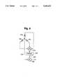
- FIG. 8is a diagram of a portion of a second alternative embodiment of the invention.
- FIG. 9is a diagram of a portion of a third alternative embodiment of the invention.
- a preferred embodiment of the present inventionis a synchronous machine 10 having a permanent magnet generator (PMG) 12, an exciter portion 14 and a main generator portion 16.
- the synchronous machine 10has a motive power shaft 18 connected to a rotor 20 attached to a prime mover 21, such as a gas turbine jet engine.
- the rotor 20carries one or more permanent magnets 22 which form poles for the PMG 12.
- Rotation of the motive power shaft 18causes relative movement between the magnetic flux produced by the permanent magnet 22 and a set of three-phase PMG armature windings including phase windings 24a-c mounted within a stator 26 of the generator 10.
- the prime mover 21 and the generator 10may comprise portions of an aircraft auxiliary power unit (APU) or any other power supply.
- APUaircraft auxiliary power unit
- the exciter portion 14includes a field winding 28 disposed in the stator 26 and a set of three-phase armature windings 30a-c disposed on the rotor 20, A set of rotating rectifiers 32 interconnect the exciter armature windings 30a-c and a main generator portion field winding 34 also disposed on the rotor 20 A set of three-phase, wye-connected main generator portion armature windings 36a-c are disposed in the stator 26.
- the synchronous machine 10may be operated in a generating mode, during which PMG armature windings 24a-c are coupled through a rectifier 38 and voltage regulator 40 to the exciter portion field winding 28 via a pair of contactors or mode switches 42a-b.
- power produced in the PMG armature windings 24a-cis rectified, regulated and delivered to the field winding 28.
- AC poweris produced in the armature windings 30a-c, rectified by the rotating rectifiers 32 and applied to the main generator portion field winding 34. Rotation of the motive power shaft 18 and the field winding 34 induces three-phase AC voltages in the main generator portion armature windings 36a-c.
- Those three-phase voltagesare provided to a rectifier/filter 48 that generates a DC voltage and provides that voltage to a main inverter 52 via a DC link 54 and a pair of mode switches 50a-b.
- the main inverter 52generates three-phase, constant-frequency AC power which is provided to a filter 58 via three mode switches 60a-c. After the three-phase AC power is filtered, it is provided to a load bus 62 for distribution.
- the main inverter 52includes six controllable transistor power switches which, during the generate mode, are switched at a constant rate so that the DC power generated on the DC link 54 by the main generator portion armature windings 36a-c is converted to constant-frequency AC power and provided to the load bus 62.
- the switches 60a-care positioned to connect main inverter 52 to supply variable-frequency power to the armature windings 36a-c via three lines 64a-c to accelerate the rotor 20 with respect to the stator 26.
- the main inverter 52generates that variable-frequency power from a voltage provided across the DC link 54, which voltage is generated by an inverter controller 70 and provided to the DC link 54 via mode switches 50a-b and lines 73a-b.
- the inverter controller 70also generates six drive signals that are provided to the six power switches of the main inverter 52 via lines 74a-f to accelerate the rotor 20 with respect to the stator 26.
- the inverter controller 70may also be connected to supply power to the exciter field winding 28 via a pair of lines 78a-b and the switches 42a-b during the starting mode.
- FIG. 2a cross section of a portion of a simplified one-pole version of the stator 26 and the rotor 20 are shown.
- the stator 26has three phase windings 36a-c which comprise a central member 26a-c about which the wire coils (not shown) are formed. Typically, the stator 26 would have more poles.
- the rotor 20has a first end 20a and a second end 20b. As shown in FIG. 2, the first rotor end 20a is aligned at an angle ⁇ with respect to the phase winding 36a; the second rotor end 20b is aligned at an angle ⁇ +60° with respect to the second phase winding 36b; and the second rotor end 20b is aligned at an angle 60°- ⁇ with respect to the third phase winding 36c.
- R acis the reluctance between the phase windings 36a, 36c
- R abis the reluctance between the phase windings 36a, 36b
- K 1is a first constant
- K 2is a second constant
- ⁇is the angle defined in FIG. 2.
- the differential reluctance between various pairs of the three phase windings 36a-36calso varies as a function of rotor position.
- the differential reluctanceis the difference between the reluctance between a first pair of windings and a second pair of windings.
- the differential reluctance between phase windings 36b, 36creferred to herein as R b-c
- R ab -R acis the difference between R ab -R ac .
- the differential reluctance R b-cis zero when the rotor 20 is vertically aligned in FIG. 2. From equations [1] and [2] above, the differential reluctance R b-c is as follows:
- Equation [5] abovecan be further simplified to show that the differential reluctance R b-c is proportional to sin 2 ⁇ .
- the differential reluctances R a-c and R a-bcan be shown to be proportional to sin 2( ⁇ -60°) and sin 2( ⁇ +60°), respectively.
- FIG. 3Aillustrates the main inverter 52 when it is connected to the phase windings 36a-c by the switches 60a-c (not shown in FIG. 3A) during the starting mode and a portion of the inverter controller 70 which generates a rotor position signal based on the differential reluctance between successively selected pairs of phase windings 36a-36c.
- the inverter 52includes six controllable transistor power switches T 1 through T 6 and six flyback diodes connected in a bridge configuration. The actuation of the power switches T 1 -T 6 is controlled by the drive signals provided via the lines 74a-f, which signals are shown as waveforms WT1 through WT6 in FIG. 4.
- the positive portions of the waveforms WT1-WT6may be pulse-width modulated (not shown) by a PWM carrier signal having a much higher frequency than that of the waveforms WT1-WT6.
- the inverter controller 70includes a phase selector 90 which also receives the six drive signals WT1-WT6 on the lines 74a-f and generates therefrom three switch actuator signals on three lines 92a-c which are used to selectively activate three switches 94a-c, each of which has an input connected to one of the phase windings 36a-c.
- Each of the switches 94a-chas a first output, shown at the bottom left portion of each switch, which is connected to the noninverting input of a summing amplifier 100 via a line 102.
- Each of the switches 94a-chas a second output, shown at the bottom right portion of each switch, which is connected to one of three noninverting inputs of a summing amplifier 106 via one of three lines 108a-c.
- phase windings 36a-cthere is current flowing through exactly two of the three phase windings 36a-c, with the third phase winding having no current passing therethrough, or being "unenergized."
- the currents passing through the phase windings 36a-care shown represented as I A , I B , I C , respectively, in FIG. 4.
- the phase selector 90generates the switch actuator signals on the lines 92a-c so that the voltage generated on the unenergized phase winding, which is generated as a result of transformer coupling to the energized phase windings, is provided to the noninverting input of the summing amplifier 100. That is accomplished by causing the switch 94 connected to the unenergized phase winding to connect its input to the output shown at the bottom left portion of the switch.
- the switch inputis connected to the output shown at the bottom right portion of the switch, so that the voltages on the two energized phase windings are provided to two of the noninverting inputs of the summing amplifier 106.
- the switch positions as shown in FIG. 3Awould occur when the phase winding 36b was unenergized and the phase windings 36a, 36c were energized.
- the switch actuator signals generated by the phase selector 90 on the lines 92a-care designated S1-S3, respectively, in FIG. 4 and are shown with respect to the waveforms WT1-WT6 from which they are generated.
- the switch actuator signal S1has a high value when neither waveform WT1 nor WT4 has a high value; the signal S2 has a high value when neither waveform WT3 nor WT6 has a high value; and the signal S3 has a high value when neither waveform WT2 nor WT5 has a high value.
- two of the three windings 36a-care energized, leaving the third winding unenergized.
- the switches 94a-care repeatedly switched, as described above, so that the voltage on the unenergized winding is always provided to the noninverting input of the summing amplifier 100 via the line 102 and the voltages on the energized phase windings are always provided to the summing amplifier 106.
- the amplifier 106sums the voltages of the two energized windings, and the sum is provided to a divider 110 which divides the sum by the number of energized phase voltages used to generate the voltage sum, which in this case is two, to generate an average phase voltage signal.
- the voltage on the unenergized phase windingwill have a relatively large DC component and a relatively small AC component with a phase or envelope representative of rotor position. For example, if the voltage difference between the lines 54a and 54b is 270 volts, the DC component of the unenergized phase voltage would be approximately 135 volts, and the average of the voltages of the two energized phase windings would be approximately 135 volts.
- the relatively small AC component of the unenergized phase voltagemight be one volt peak-to-peak.
- the average phase voltage signal generated by the divider 110is provided to the inverting input of the summing amplifier 100, where it is subtracted from the unenergized phase voltage, resulting in the AC component of the unenergized phase voltage which is representative of rotor position.
- the positive portions of the pulses of waveforms WT1-WT6 shown in FIG. 4may be pulse-width modulated (not shown) by a carrier signal having a much higher frequency than the waveforms WT1-WT6.
- the rotor position signal generated by the summing amplifier 100will have a frequency and phase the same as the PWM carrier frequency, but the magnitude, or envelope, of the signal will vary at a much lower frequency with a phase which is representative of rotor position.
- the output of the summing amplifier 100is provided to a synchronous demodulator circuit comprising a multiplier 112 and a low pass filter 114.
- the multiplier 112comprises an inverter 116 and a two-input switch 118.
- a first input of the switch 118is connected to receive the rotor position signal from the amplifier 100, and a second output of the switch 118 is connected to receive an inverted rotor position signal from the inverter 116.
- the switch 118is switched at the frequency of the PWM carrier signal to alternately provide at its output the uninverted and inverted rotor position signal.
- This particular multiplier circuit 112is used in the case of a square-wave PWM carrier signal. Other types of multiplier circuits and synchronous demodulator circuits could also be used.
- the demodulated rotor position signalis generated on a line 120 and provided to a portion of the inverter controller 70, shown in FIG. 3B, which converts the rotor position signal into a clock signal and generates from that clock signal the six drive signals WT1-WT6 for controlling the transistor power switches T 1 -T 6 of the main inverter 52.
- the rotor position signal on the line 120is provided to the negative input of a first comparator 130 and the positive input of a second comparator 132.
- the first comparator 130determines when the magnitude of the rotor position signal is more negative than a predetermined negative voltage, -V ref
- the second comparator 132determines when the magnitude of the rotor position signal is greater than a predetermined positive voltage, +V ref .
- the clock signalis generated from the output of the comparators 130, 132 by a 1-of-2 data selector comprising a pair of AND gates 140, 142, an OR gate 144, and an inverter 146.
- a first binary data select signalis provided to the AND gate 142 via a line 152 and a second binary data select signal is provided to the AND gate 140 via the inverter 146 connected to the line 152.
- the data select signalswhich at all times are complemented with respect to each other, are generated from the least-significant bit (LSB) of a counter 150 so that the data select signals values switch each time the count of the counter increases by one.
- the rotor position signal, the +V ref and -V ref signals, and the clock signal generated by the OR gate 144are shown in FIG. 5.
- the rising edge of each pulse of the clock signalis triggered alternately by the magnitude of the rotor position signal reaching the predetermined +V ref and -V ref signals.
- the rising edge of each clock pulsetriggers the counter 150 to increase the count, causing the binary value of the least-significant bit to change and the magnitudes of the data select signals to switch.
- the AND gate 140 or 142 that generated the high binary value(when either the +V ref or -V ref magnitude was exceeded) is no longer selected, and the clock signal magnitude falls to zero shortly after each rising edge.
- the actual shape of the rotor position signal generated on the line 120would approximate the waveform produced by horizontally compressing the bold portions of the sinusoidal signal, which fall between the +V ref and -V ref thresholds, so that they were joined together. The actual shape would thus approximate a triangular waveform.
- the magnitude of the actual rotor position signaldoes not substantially exceed the +V ref and -V ref thresholds because, when the rotor position signal reaches each threshold, the drive signals on the lines 74a-f cause the rotor 20 to be advanced 60 electrical degrees shortly thereafter.
- the magnitudes of the +V ref and -V ref thresholdsshould be selected so that the horizontal "spacing" between the bold portions of the rotor position signal corresponds to 60 electrical degrees, as shown in FIG. 5.
- the magnitudes of the +V ref and -V ref thresholdsmay be selected to be a predetermined percentage of the voltage across the DC link 54a-b, the percentage being based upon generator parameters.
- the counter 150is a modulo-six counter having a three-bit binary output.
- the output of the counter 150is provided to a logic unit 160 which generates the six transistor drive signals WT1-WT6 in accordance with the counter output in accordance with the table shown in FIG. 6.
- the counter 150can be initialized with one of six initial counts so that one set of drive signals is generated on the lines 74a-f. If the counter 150 does not increment within a predetermined period of time, meaning that the initial set of drive signals did not cause any torque to be produced on the rotor 20, the counter 150 can be loaded with another one of the six initial counts until the correct count is loaded. The loading of the initial counts could be performed by a digital signal processor coupled to the counter 150.
- the 1-of-2 selector, the counter 150, the logic unit 160, and/or other features of the described embodimentcould be implemented with a digital signal processor executing a computer program.
- phase windings 36a-care connected to three switches 170a-c, respectively, each of which has a single output connected to the noninverting input of a summing amplifier 172.
- the switches 170a-care switched such that the unenergized phase winding is connected to the noninverting input of the summing amplifier 172.
- Each of the phase windings 36a-cis also connected to a respective noninverting input of a summing amplifier 174, which generates a signal representing the sum of the phase winding voltages.
- the phase voltage sumis provided to a divider 176, which divides the phase voltage sum by three to generate a signal representing the average phase voltage.
- the average phase voltageis provided to the inverting input of the amplifier 172 whereby that voltage is subtracted from the voltage at the unenergized phase winding.
- the output of the summing amplifier 172would be provided to the multiplier circuit 112 of FIG. 3A.
- phase windings 36a-care connected to three switches 180a-c, respectively, which are switched so that the unenergized phase winding is connected to the noninverting input of a summing amplifier 182.
- the junction of the phase windings 36a-cis connected to the inverting input of the amplifier 182 so that the voltage at the junction of the windings is subtracted from the voltage at the unenergized phase winding.
- the output of the summing amplifier 182would be provided to the multiplier circuit 112 of FIG. 3A.
- the inverting input of the amplifier 182could be coupled via dotted line 190, to the junction of a pair of identical resistors 192, 194 provided across the DC link 54a-b so that the inverting input of amplifier 182 would receive a signal representing one-half the voltage across the DC link 54a-b.
- FIG. 9A portion of a further alternative embodiment is illustrated in FIG. 9.
- rotor positionis detected based on inductance sensing instead of differential reluctance sensing.
- the voltages on all three phase windings 36a-care provided to a summing amplifier 200, which generates a signal representing the voltage sum.
- the voltage sum signalis provided to a divider 202, which divides the voltage sum signal by three to generate an average phase voltage signal on a line 203.
- the voltage at the junction of the wye-connected windings 36a-cis provided via a line 204 to the noninverting input of a summing amplifier 206.
- the summing amplifier 206generates a rotor position signal by subtracting the average phase voltage signal on the line 203 from the junction voltage on the line 204.
- the average phase voltage signal on the line 203could be generated in other ways. For example, it could be generated by dividing the sum of the voltages on the energized phase windings by two, or it could be generated by dividing the DC link voltage by two.
- sensing rotor positioncould be used for only a portion of the time during the starting mode of operation.
- the above methodcould be used during the initial portion of the starting mode when the rotor 20 is at relatively low speed, and a method of detecting rotor position based on back EMF could be used for the latter portion of the starting mode when the rotor 20 is at relatively high speed.
- sensing rotor position based on back EMFcould be used, for example, when the magnitude of the back EMF reaches a predetermined threshold and/or when the rotor reaches a predetermined rotational speed.
Landscapes
- Engineering & Computer Science (AREA)
- Chemical & Material Sciences (AREA)
- Combustion & Propulsion (AREA)
- Mechanical Engineering (AREA)
- General Engineering & Computer Science (AREA)
- Power Engineering (AREA)
- Control Of Eletrric Generators (AREA)
Abstract
Description
R.sub.ac =K.sub.1 +K.sub.2 cos θ cos (60°-θ), [1]
R.sub.ab =K.sub.1 +K.sub.2 cos θ cos (θ+60°), [2]
R.sub.b-c =R.sub.ab -R.sub.ac [ 3]
R.sub.b-c =K.sub.1 +K.sub.2 cos θ cos (θ+60°)-K.sub.1 -K.sub.2 cos θ cos (60°θ) [4]
R.sub.b-c =K.sub.2 [cos θ cos (θ+60°)-cos θ cos (60°-θ)] [5]
Claims (27)
Priority Applications (1)
| Application Number | Priority Date | Filing Date | Title |
|---|---|---|---|
| US08/061,168US5363032A (en) | 1993-05-12 | 1993-05-12 | Sensorless start of synchronous machine |
Applications Claiming Priority (1)
| Application Number | Priority Date | Filing Date | Title |
|---|---|---|---|
| US08/061,168US5363032A (en) | 1993-05-12 | 1993-05-12 | Sensorless start of synchronous machine |
Publications (1)
| Publication Number | Publication Date |
|---|---|
| US5363032Atrue US5363032A (en) | 1994-11-08 |
Family
ID=22034080
Family Applications (1)
| Application Number | Title | Priority Date | Filing Date |
|---|---|---|---|
| US08/061,168Expired - LifetimeUS5363032A (en) | 1993-05-12 | 1993-05-12 | Sensorless start of synchronous machine |
Country Status (1)
| Country | Link |
|---|---|
| US (1) | US5363032A (en) |
Cited By (43)
| Publication number | Priority date | Publication date | Assignee | Title |
|---|---|---|---|---|
| US5497064A (en)* | 1995-03-14 | 1996-03-05 | A. O. Smith Corporation | Apparatus for starting a switched reluctance motor |
| US5525886A (en)* | 1994-06-23 | 1996-06-11 | General Electric Company | Low speed position estimator for switched reluctance machine using flux/current model |
| EP0826269A4 (en)* | 1994-11-15 | 1998-03-04 | ||
| US5751125A (en)* | 1995-11-08 | 1998-05-12 | The Penn State Research Foundation | Artificial heart with sensorless motor |
| US5818192A (en)* | 1995-08-04 | 1998-10-06 | The Boeing Company | Starting of synchronous machine without rotor position of speed measurement |
| US5903116A (en)* | 1997-09-08 | 1999-05-11 | Capstone Turbine Corporation | Turbogenerator/motor controller |
| US5998880A (en)* | 1997-08-07 | 1999-12-07 | General Electric Company | AC locomotive operation without DC current sensor |
| US6031294A (en)* | 1998-01-05 | 2000-02-29 | Capstone Turbine Corporation | Turbogenerator/motor controller with ancillary energy storage/discharge |
| US6153942A (en)* | 1995-07-17 | 2000-11-28 | Lucas Aerospace Power Equipment Corp. | Starter/generator speed sensing using field weakening |
| US6307275B1 (en)* | 2000-01-31 | 2001-10-23 | Ford Global Technologies, Inc. | Method and apparatus for controlling a high-speed AC permanent magnet synchronous motor coupled to an industrial turbo engine |
| US6487096B1 (en) | 1997-09-08 | 2002-11-26 | Capstone Turbine Corporation | Power controller |
| US6486640B2 (en)* | 2000-02-22 | 2002-11-26 | Lucas Industries Limited | Control system for variable frequency generator |
| US6612112B2 (en) | 1998-12-08 | 2003-09-02 | Capstone Turbine Corporation | Transient turbine exhaust temperature control for a turbogenerator |
| US6707276B2 (en)* | 2000-06-26 | 2004-03-16 | Denso Corporation | Voltage regulator of AC generator having circuit for detecting voltage induced in field coil |
| US20040080165A1 (en)* | 2001-12-31 | 2004-04-29 | Capstone Turbine Corporation | Turbogenerator/motor controller with ancillary energy storage/discharge |
| US20040108726A1 (en)* | 2002-12-10 | 2004-06-10 | Bulent Sarlioglu | Method and system for providing single-phase excitation techniques to a start exciter in a starter/generator system |
| US20040113571A1 (en)* | 2002-12-12 | 2004-06-17 | General Electric Company | Method and system using traction inverter for locked axle detection |
| US6784565B2 (en) | 1997-09-08 | 2004-08-31 | Capstone Turbine Corporation | Turbogenerator with electrical brake |
| US6787933B2 (en) | 2001-01-10 | 2004-09-07 | Capstone Turbine Corporation | Power generation system having transient ride-through/load-leveling capabilities |
| US6809496B2 (en) | 2002-09-16 | 2004-10-26 | Honeywell International Inc. | Position sensor emulator for a synchronous motor/generator |
| US6844707B1 (en) | 2003-12-30 | 2005-01-18 | Pacific Scientific/Electro Kinetics Division | AC/DC brushless starter-generator |
| US6870279B2 (en) | 1998-01-05 | 2005-03-22 | Capstone Turbine Corporation | Method and system for control of turbogenerator power and temperature |
| US6960840B2 (en) | 1998-04-02 | 2005-11-01 | Capstone Turbine Corporation | Integrated turbine power generation system with catalytic reactor |
| US20060249957A1 (en)* | 2002-11-15 | 2006-11-09 | Ryosuke Ito | Wind power generator |
| US20070040524A1 (en)* | 2005-08-17 | 2007-02-22 | Honeywell International Inc. | Power factor control for floating frame controller for sensorless control of synchronous machines |
| US20080164851A1 (en)* | 2007-01-09 | 2008-07-10 | Honeywell International Inc. | Dc bus short circuit compliant power generation systems using induction machine |
| US20090012742A1 (en)* | 2007-07-02 | 2009-01-08 | Eldery Mohamed A | Energy based position and speed self-sensing method and apparatus for synchronous machine |
| EP2109212A1 (en) | 2008-04-10 | 2009-10-14 | Hamilton Sundstrand Corporation | Direct flux regulated permanent magnet brushless motor utilizing sensorless control |
| US20100045222A1 (en)* | 2008-08-20 | 2010-02-25 | Rozman Gregory I | Direct flux regulated permanent magnet brushless motor utilizing sensorless control by dc and ac excitation |
| US20100308582A1 (en)* | 2009-06-05 | 2010-12-09 | Hamilton Sundstrand Corporation | Starting/generating system with multi-functional circuit breaker |
| US20110133703A1 (en)* | 2009-12-03 | 2011-06-09 | Hamilton Sundstrand Corporation | Architecture for dual source electric power generating system |
| US20110181220A1 (en)* | 2008-10-01 | 2011-07-28 | Toshiba Mitsubishi-Electric Indus. Sys.Corp. | Synchronous machine starting device |
| US20120098261A1 (en)* | 2010-10-22 | 2012-04-26 | Hamilton Sundstrand Corporation | Systems and Methods Involving Electrical Start and Power Generation |
| CN102684588A (en)* | 2012-05-31 | 2012-09-19 | 宁波乐邦电气有限公司 | Starting detection device and starting method for permanent magnetic synchronous motor speed sensorless |
| US8836293B1 (en)* | 2013-03-15 | 2014-09-16 | Hamilton Sundstrand Corporation | Variable speed constant frequency system with generator and rotating power converter |
| US8912765B2 (en) | 2013-03-15 | 2014-12-16 | Hamilton Sundstrand Corporation | EPGS architecture with multi-channel synchronous generator and common unregulated PMG exciter |
| US8928293B1 (en)* | 2013-08-02 | 2015-01-06 | Hamilton Sundstrand Corporation | Systems for wound field synchronous machines with zero speed rotor position detection during start for motoring and improved transient response for generation |
| US8975876B2 (en) | 2013-03-15 | 2015-03-10 | Hamilton Sunstrand Corporation | Method of controlling rotating main field converter |
| US20150180394A1 (en)* | 2013-12-25 | 2015-06-25 | Delta Electronics, Inc. | Generator brake system and method of controlling the same |
| US9252695B2 (en)* | 2014-03-12 | 2016-02-02 | General Electric Company | Brushless permanent magnet generator plus auxiliary voltage source constant potential exciter |
| US9257889B2 (en) | 2013-03-15 | 2016-02-09 | Hamilton Sundstrand Corporation | EPGS architecture with multi-channel synchronous generator and common field regulated exciter |
| US9300194B2 (en) | 2011-11-09 | 2016-03-29 | Hamilton Sundstrand Corporation | Electromagnetic device |
| US20170072924A1 (en)* | 2014-05-21 | 2017-03-16 | Continental Teves Ag & Co. Ohg | Method for Controlling a Brake System |
Citations (49)
| Publication number | Priority date | Publication date | Assignee | Title |
|---|---|---|---|---|
| US3775974A (en)* | 1972-06-05 | 1973-12-04 | J Silver | Gas turbine engine |
| US3902073A (en)* | 1974-02-07 | 1975-08-26 | Gen Electric | Starter generator electrical system utilizing phase controlled rectifiers to drive a dynamoelectric machine as a brushless dc motor in the starter mode and to provide frequency conversion for a constant frequency output in the generating mode |
| US3908161A (en)* | 1974-02-07 | 1975-09-23 | Gen Electric | Field excitation system for synchronous machines utilizing a rotating transformer brushless exciter generating combination |
| US4093869A (en)* | 1976-04-13 | 1978-06-06 | Westinghouse Electric Corp. | Quadrature axis field brushless exciter |
| US4295085A (en)* | 1979-05-25 | 1981-10-13 | General Electric Company | Phase lock loop commutation position control and method |
| US4354126A (en)* | 1980-09-12 | 1982-10-12 | Westinghouse Electric Corp. | Dynamoelectric machine with a permanent magnet rotor having laminated poles |
| US4456830A (en)* | 1982-04-22 | 1984-06-26 | Lockheed Corporation | AC Motor-starting for aircraft engines using APU free turbine driven generators |
| US4473752A (en)* | 1982-05-27 | 1984-09-25 | Lockheed Corporation | Aircraft engine starting with synchronous ac generator |
| US4684081A (en)* | 1986-06-11 | 1987-08-04 | Lockheed Corporation | Multifunction power system for an aircraft |
| US4687961A (en)* | 1986-03-17 | 1987-08-18 | Seiberco Incorporated | Polyphase DC motor with sensor poles |
| US4694210A (en)* | 1986-07-31 | 1987-09-15 | General Motors Corporation | Brushless DC motor and sensorless drive arrangement therefor |
| US4708030A (en)* | 1985-03-18 | 1987-11-24 | Sundstrand Corporation | Multi-range starter-generator drive |
| US4743777A (en)* | 1986-03-07 | 1988-05-10 | Westinghouse Electric Corp. | Starter generator system with two stator exciter windings |
| US4754220A (en)* | 1980-10-21 | 1988-06-28 | Kabushiki Kaisha Sg | Digital output rotational position detection device |
| US4772802A (en)* | 1987-08-19 | 1988-09-20 | Sundstrand Corporation | Starting/generating system |
| GB2206751A (en)* | 1987-05-29 | 1989-01-11 | Shinko Electric Co Ltd | Starting a variable speed constant frequency generating system |
| US4808903A (en)* | 1987-04-13 | 1989-02-28 | Hitachi, Ltd. | Vector control system for induction motors |
| US4841216A (en)* | 1987-07-24 | 1989-06-20 | Shinko Electric Co., Ltd. | Engine start type VSCF generating system |
| US4868406A (en)* | 1988-07-05 | 1989-09-19 | Sundstrand Corporation | Electrically compensated constant speed drive with prime mover start capability |
| US4900231A (en)* | 1986-05-30 | 1990-02-13 | The Boeing Company | Auxiliary compressor air supply for an aircraft |
| US4929021A (en)* | 1988-11-14 | 1990-05-29 | Designs For Leisure, Ltd. | Ornament displaying furniture |
| US4933623A (en)* | 1988-12-29 | 1990-06-12 | Westinghouse Electric Corp. | Generator voltage regulator power circuit |
| US4935686A (en)* | 1989-08-18 | 1990-06-19 | Westinghouse Electric Corp. | Ac motor drive with switched autotransformer coupling |
| US4939441A (en)* | 1989-10-27 | 1990-07-03 | Sundstrand Corporation | Excitation system for a brushless generator having separate AC and DC exciter field windings |
| US4942493A (en)* | 1988-11-02 | 1990-07-17 | Sundstrand Corporation | Method and apparatus for detecting prime mover start malfunction |
| US4947100A (en)* | 1989-10-16 | 1990-08-07 | Sundstrand Corporation | Power conversion system with stepped waveform inverter having prime mover start capability |
| US4959595A (en)* | 1988-02-12 | 1990-09-25 | Mitsubishi Denki Kabushiki Kaisha | Rotating electric machine having a coil coaxial with rotating shaft |
| US4967334A (en)* | 1989-09-12 | 1990-10-30 | Sundstrand Corporation | Inverter input/output filter system |
| US4968926A (en)* | 1989-10-25 | 1990-11-06 | Sundstrand Corporation | Power conversion system with stepped waveform DC to AC converter having prime mover start capability |
| US4988939A (en)* | 1989-08-04 | 1991-01-29 | Thor Technology Corporation | Electric motor with variable commutation delay |
| US4992721A (en)* | 1990-01-26 | 1991-02-12 | Sundstrand Corporation | Inverter for starting/generating system |
| US5008801A (en)* | 1989-12-11 | 1991-04-16 | Sundstrand Corporation | VSCF power conversion system using an output autotransformer |
| US5012177A (en)* | 1989-12-19 | 1991-04-30 | Sundstrand Corporation | Power conversion system using a switched reluctance motor/generator |
| US5013929A (en)* | 1989-11-22 | 1991-05-07 | Sundstrand Corporation | Power conversion system having prime mover start capability |
| US5015941A (en)* | 1989-10-30 | 1991-05-14 | Sundstrand Corporation | Power conversion system with bi-directional power converter having prime mover start capability |
| US5015927A (en)* | 1989-08-04 | 1991-05-14 | Thor Technology Corporation | Electric motor with regeneration current commutation |
| US5028803A (en)* | 1989-03-22 | 1991-07-02 | Sundstrand Corporation | Integrated drive generator system with direct motor drive prime mover starting |
| US5040366A (en)* | 1989-01-13 | 1991-08-20 | General Electric Company | Fluid transfer device |
| US5051670A (en)* | 1990-07-30 | 1991-09-24 | Aircraft Parts Corp. | Aircraft DC starter-generator torque controller |
| US5051680A (en)* | 1989-12-08 | 1991-09-24 | Sundstrand Corporation | Simple starting sequence for variable reluctance motors without rotor position sensor |
| US5055700A (en)* | 1989-10-16 | 1991-10-08 | Dhyanchand P John | Brushless generator having prime mover start capability |
| US5055764A (en)* | 1989-12-11 | 1991-10-08 | Sundstrand Corporation | Low voltage aircraft engine starting system |
| US5068590A (en)* | 1989-12-20 | 1991-11-26 | Sundstrand Corporation | Brushless generator having AC excitation in generating and starting modes |
| US5079494A (en)* | 1989-05-23 | 1992-01-07 | Thor Technology Corporation | Fast response motor current regulator |
| US5097195A (en)* | 1989-11-27 | 1992-03-17 | Sundstrand Corporation | AC exciter for VSCF starter/generator |
| US5113125A (en)* | 1991-05-01 | 1992-05-12 | Westinghouse Electric Corp. | AC drive with optimized torque |
| US5132604A (en)* | 1989-04-04 | 1992-07-21 | Honda Giken Kogyo Kabushiki Kaisha | Engine starter and electric generator system |
| US5140245A (en)* | 1990-09-24 | 1992-08-18 | Westinghouse Electric Corp. | Pmg-based position sensor and synchronous drive incorporating same |
| US5189353A (en)* | 1990-11-02 | 1993-02-23 | Nippon Seiko Kabushiki Kaisha | Resolver system |
- 1993
- 1993-05-12USUS08/061,168patent/US5363032A/ennot_activeExpired - Lifetime
Patent Citations (49)
| Publication number | Priority date | Publication date | Assignee | Title |
|---|---|---|---|---|
| US3775974A (en)* | 1972-06-05 | 1973-12-04 | J Silver | Gas turbine engine |
| US3902073A (en)* | 1974-02-07 | 1975-08-26 | Gen Electric | Starter generator electrical system utilizing phase controlled rectifiers to drive a dynamoelectric machine as a brushless dc motor in the starter mode and to provide frequency conversion for a constant frequency output in the generating mode |
| US3908161A (en)* | 1974-02-07 | 1975-09-23 | Gen Electric | Field excitation system for synchronous machines utilizing a rotating transformer brushless exciter generating combination |
| US4093869A (en)* | 1976-04-13 | 1978-06-06 | Westinghouse Electric Corp. | Quadrature axis field brushless exciter |
| US4295085A (en)* | 1979-05-25 | 1981-10-13 | General Electric Company | Phase lock loop commutation position control and method |
| US4354126A (en)* | 1980-09-12 | 1982-10-12 | Westinghouse Electric Corp. | Dynamoelectric machine with a permanent magnet rotor having laminated poles |
| US4754220A (en)* | 1980-10-21 | 1988-06-28 | Kabushiki Kaisha Sg | Digital output rotational position detection device |
| US4456830A (en)* | 1982-04-22 | 1984-06-26 | Lockheed Corporation | AC Motor-starting for aircraft engines using APU free turbine driven generators |
| US4473752A (en)* | 1982-05-27 | 1984-09-25 | Lockheed Corporation | Aircraft engine starting with synchronous ac generator |
| US4708030A (en)* | 1985-03-18 | 1987-11-24 | Sundstrand Corporation | Multi-range starter-generator drive |
| US4743777A (en)* | 1986-03-07 | 1988-05-10 | Westinghouse Electric Corp. | Starter generator system with two stator exciter windings |
| US4687961A (en)* | 1986-03-17 | 1987-08-18 | Seiberco Incorporated | Polyphase DC motor with sensor poles |
| US4900231A (en)* | 1986-05-30 | 1990-02-13 | The Boeing Company | Auxiliary compressor air supply for an aircraft |
| US4684081A (en)* | 1986-06-11 | 1987-08-04 | Lockheed Corporation | Multifunction power system for an aircraft |
| US4694210A (en)* | 1986-07-31 | 1987-09-15 | General Motors Corporation | Brushless DC motor and sensorless drive arrangement therefor |
| US4808903A (en)* | 1987-04-13 | 1989-02-28 | Hitachi, Ltd. | Vector control system for induction motors |
| GB2206751A (en)* | 1987-05-29 | 1989-01-11 | Shinko Electric Co Ltd | Starting a variable speed constant frequency generating system |
| US4841216A (en)* | 1987-07-24 | 1989-06-20 | Shinko Electric Co., Ltd. | Engine start type VSCF generating system |
| US4772802A (en)* | 1987-08-19 | 1988-09-20 | Sundstrand Corporation | Starting/generating system |
| US4959595A (en)* | 1988-02-12 | 1990-09-25 | Mitsubishi Denki Kabushiki Kaisha | Rotating electric machine having a coil coaxial with rotating shaft |
| US4868406A (en)* | 1988-07-05 | 1989-09-19 | Sundstrand Corporation | Electrically compensated constant speed drive with prime mover start capability |
| US4942493A (en)* | 1988-11-02 | 1990-07-17 | Sundstrand Corporation | Method and apparatus for detecting prime mover start malfunction |
| US4929021A (en)* | 1988-11-14 | 1990-05-29 | Designs For Leisure, Ltd. | Ornament displaying furniture |
| US4933623A (en)* | 1988-12-29 | 1990-06-12 | Westinghouse Electric Corp. | Generator voltage regulator power circuit |
| US5040366A (en)* | 1989-01-13 | 1991-08-20 | General Electric Company | Fluid transfer device |
| US5028803A (en)* | 1989-03-22 | 1991-07-02 | Sundstrand Corporation | Integrated drive generator system with direct motor drive prime mover starting |
| US5132604A (en)* | 1989-04-04 | 1992-07-21 | Honda Giken Kogyo Kabushiki Kaisha | Engine starter and electric generator system |
| US5079494A (en)* | 1989-05-23 | 1992-01-07 | Thor Technology Corporation | Fast response motor current regulator |
| US5015927A (en)* | 1989-08-04 | 1991-05-14 | Thor Technology Corporation | Electric motor with regeneration current commutation |
| US4988939A (en)* | 1989-08-04 | 1991-01-29 | Thor Technology Corporation | Electric motor with variable commutation delay |
| US4935686A (en)* | 1989-08-18 | 1990-06-19 | Westinghouse Electric Corp. | Ac motor drive with switched autotransformer coupling |
| US4967334A (en)* | 1989-09-12 | 1990-10-30 | Sundstrand Corporation | Inverter input/output filter system |
| US4947100A (en)* | 1989-10-16 | 1990-08-07 | Sundstrand Corporation | Power conversion system with stepped waveform inverter having prime mover start capability |
| US5055700A (en)* | 1989-10-16 | 1991-10-08 | Dhyanchand P John | Brushless generator having prime mover start capability |
| US4968926A (en)* | 1989-10-25 | 1990-11-06 | Sundstrand Corporation | Power conversion system with stepped waveform DC to AC converter having prime mover start capability |
| US4939441A (en)* | 1989-10-27 | 1990-07-03 | Sundstrand Corporation | Excitation system for a brushless generator having separate AC and DC exciter field windings |
| US5015941A (en)* | 1989-10-30 | 1991-05-14 | Sundstrand Corporation | Power conversion system with bi-directional power converter having prime mover start capability |
| US5013929A (en)* | 1989-11-22 | 1991-05-07 | Sundstrand Corporation | Power conversion system having prime mover start capability |
| US5097195A (en)* | 1989-11-27 | 1992-03-17 | Sundstrand Corporation | AC exciter for VSCF starter/generator |
| US5051680A (en)* | 1989-12-08 | 1991-09-24 | Sundstrand Corporation | Simple starting sequence for variable reluctance motors without rotor position sensor |
| US5055764A (en)* | 1989-12-11 | 1991-10-08 | Sundstrand Corporation | Low voltage aircraft engine starting system |
| US5008801A (en)* | 1989-12-11 | 1991-04-16 | Sundstrand Corporation | VSCF power conversion system using an output autotransformer |
| US5012177A (en)* | 1989-12-19 | 1991-04-30 | Sundstrand Corporation | Power conversion system using a switched reluctance motor/generator |
| US5068590A (en)* | 1989-12-20 | 1991-11-26 | Sundstrand Corporation | Brushless generator having AC excitation in generating and starting modes |
| US4992721A (en)* | 1990-01-26 | 1991-02-12 | Sundstrand Corporation | Inverter for starting/generating system |
| US5051670A (en)* | 1990-07-30 | 1991-09-24 | Aircraft Parts Corp. | Aircraft DC starter-generator torque controller |
| US5140245A (en)* | 1990-09-24 | 1992-08-18 | Westinghouse Electric Corp. | Pmg-based position sensor and synchronous drive incorporating same |
| US5189353A (en)* | 1990-11-02 | 1993-02-23 | Nippon Seiko Kabushiki Kaisha | Resolver system |
| US5113125A (en)* | 1991-05-01 | 1992-05-12 | Westinghouse Electric Corp. | AC drive with optimized torque |
Non-Patent Citations (3)
| Title |
|---|
| E. Iizuka, et al., IEEE Transactions on Industry Applications , vol. 1A 21, No. 4, May/Jun. 1985.* |
| E. Iizuka, et al., IEEE Transactions on Industry Applications, vol. 1A-21, No. 4, May/Jun. 1985. |
| Furuhashi, et al., IEEE Transactions on Industrial Electronics, vol. 39, No. 2, Apr. 1992.* |
Cited By (65)
| Publication number | Priority date | Publication date | Assignee | Title |
|---|---|---|---|---|
| US5525886A (en)* | 1994-06-23 | 1996-06-11 | General Electric Company | Low speed position estimator for switched reluctance machine using flux/current model |
| EP0826269A4 (en)* | 1994-11-15 | 1998-03-04 | ||
| US5497064A (en)* | 1995-03-14 | 1996-03-05 | A. O. Smith Corporation | Apparatus for starting a switched reluctance motor |
| US6153942A (en)* | 1995-07-17 | 2000-11-28 | Lucas Aerospace Power Equipment Corp. | Starter/generator speed sensing using field weakening |
| US5818192A (en)* | 1995-08-04 | 1998-10-06 | The Boeing Company | Starting of synchronous machine without rotor position of speed measurement |
| US5877606A (en)* | 1995-08-04 | 1999-03-02 | The Boeing Company | Starting of synchronous machine without rotor position or speed measurement |
| US5751125A (en)* | 1995-11-08 | 1998-05-12 | The Penn State Research Foundation | Artificial heart with sensorless motor |
| US5998880A (en)* | 1997-08-07 | 1999-12-07 | General Electric Company | AC locomotive operation without DC current sensor |
| US5903116A (en)* | 1997-09-08 | 1999-05-11 | Capstone Turbine Corporation | Turbogenerator/motor controller |
| US6487096B1 (en) | 1997-09-08 | 2002-11-26 | Capstone Turbine Corporation | Power controller |
| US6784565B2 (en) | 1997-09-08 | 2004-08-31 | Capstone Turbine Corporation | Turbogenerator with electrical brake |
| USRE40713E1 (en) | 1997-09-08 | 2009-05-19 | Capstone Turbine Corporation | Turbogenerator/motor controller |
| US6031294A (en)* | 1998-01-05 | 2000-02-29 | Capstone Turbine Corporation | Turbogenerator/motor controller with ancillary energy storage/discharge |
| US6870279B2 (en) | 1998-01-05 | 2005-03-22 | Capstone Turbine Corporation | Method and system for control of turbogenerator power and temperature |
| US6960840B2 (en) | 1998-04-02 | 2005-11-01 | Capstone Turbine Corporation | Integrated turbine power generation system with catalytic reactor |
| US6612112B2 (en) | 1998-12-08 | 2003-09-02 | Capstone Turbine Corporation | Transient turbine exhaust temperature control for a turbogenerator |
| US6501244B2 (en) | 2000-01-31 | 2002-12-31 | Ballard Power Systems Corporation | Method and apparatus for controlling a high-speed AC permanent magnet synchronous motor coupled to an industrial turbo engine |
| US6492789B2 (en) | 2000-01-31 | 2002-12-10 | Ballard Power Systems Corporation | Method and apparatus for controlling a high-speed AC permanent magnet synchronous motor coupled to an industrial turbo engine |
| US6307275B1 (en)* | 2000-01-31 | 2001-10-23 | Ford Global Technologies, Inc. | Method and apparatus for controlling a high-speed AC permanent magnet synchronous motor coupled to an industrial turbo engine |
| US6486640B2 (en)* | 2000-02-22 | 2002-11-26 | Lucas Industries Limited | Control system for variable frequency generator |
| US6707276B2 (en)* | 2000-06-26 | 2004-03-16 | Denso Corporation | Voltage regulator of AC generator having circuit for detecting voltage induced in field coil |
| US6787933B2 (en) | 2001-01-10 | 2004-09-07 | Capstone Turbine Corporation | Power generation system having transient ride-through/load-leveling capabilities |
| US20040080165A1 (en)* | 2001-12-31 | 2004-04-29 | Capstone Turbine Corporation | Turbogenerator/motor controller with ancillary energy storage/discharge |
| US6809496B2 (en) | 2002-09-16 | 2004-10-26 | Honeywell International Inc. | Position sensor emulator for a synchronous motor/generator |
| US20060249957A1 (en)* | 2002-11-15 | 2006-11-09 | Ryosuke Ito | Wind power generator |
| US20090079195A1 (en)* | 2002-11-15 | 2009-03-26 | Zephyr Corporation | Wind power generator |
| US7456510B2 (en)* | 2002-11-15 | 2008-11-25 | Zephyr Corporation | Wind power generator |
| US8013459B2 (en) | 2002-11-15 | 2011-09-06 | Zephyr Corporation | Wind power generator |
| US6998726B2 (en)* | 2002-12-10 | 2006-02-14 | Honeywell International Inc. | Method and system for providing single-phase excitation techniques to a start exciter in a starter/generator system |
| US20040108726A1 (en)* | 2002-12-10 | 2004-06-10 | Bulent Sarlioglu | Method and system for providing single-phase excitation techniques to a start exciter in a starter/generator system |
| US20040113571A1 (en)* | 2002-12-12 | 2004-06-17 | General Electric Company | Method and system using traction inverter for locked axle detection |
| US6828746B2 (en) | 2002-12-12 | 2004-12-07 | General Electric Company | Method and system using traction inverter for locked axle detection |
| US6844707B1 (en) | 2003-12-30 | 2005-01-18 | Pacific Scientific/Electro Kinetics Division | AC/DC brushless starter-generator |
| US20070040524A1 (en)* | 2005-08-17 | 2007-02-22 | Honeywell International Inc. | Power factor control for floating frame controller for sensorless control of synchronous machines |
| US7495404B2 (en) | 2005-08-17 | 2009-02-24 | Honeywell International Inc. | Power factor control for floating frame controller for sensorless control of synchronous machines |
| US7459889B2 (en)* | 2007-01-09 | 2008-12-02 | Honeywell International, Inc. | DC bus short circuit compliant power generation systems using induction machine |
| US20080164851A1 (en)* | 2007-01-09 | 2008-07-10 | Honeywell International Inc. | Dc bus short circuit compliant power generation systems using induction machine |
| US7571072B2 (en)* | 2007-07-02 | 2009-08-04 | Honeywell International Inc. | Energy based position and speed self-sensing method and apparatus for synchronous machine |
| US20090012742A1 (en)* | 2007-07-02 | 2009-01-08 | Eldery Mohamed A | Energy based position and speed self-sensing method and apparatus for synchronous machine |
| US20090256511A1 (en)* | 2008-04-10 | 2009-10-15 | Rozman Gregory I | Direct Flux Regulated Permanent Magnet Brushless Motor Utilizing Sensorless Control |
| US7843155B2 (en) | 2008-04-10 | 2010-11-30 | Hamilton Sundstrand Corporation | Direct flux regulated permanent magnet brushless motor utilizing sensorless control |
| EP2109212A1 (en) | 2008-04-10 | 2009-10-14 | Hamilton Sundstrand Corporation | Direct flux regulated permanent magnet brushless motor utilizing sensorless control |
| US20100045222A1 (en)* | 2008-08-20 | 2010-02-25 | Rozman Gregory I | Direct flux regulated permanent magnet brushless motor utilizing sensorless control by dc and ac excitation |
| US8080960B2 (en) | 2008-08-20 | 2011-12-20 | Hamilton Sundstrand Corporation | Direct flux regulated permanent magnet brushless motor utilizing sensorless control by DC and AC excitation |
| US8519656B2 (en)* | 2008-10-01 | 2013-08-27 | Toshiba Mitsubishi-Electric Industrial Systems Corporation | Synchronous machine starting device |
| US20110181220A1 (en)* | 2008-10-01 | 2011-07-28 | Toshiba Mitsubishi-Electric Indus. Sys.Corp. | Synchronous machine starting device |
| US20100308582A1 (en)* | 2009-06-05 | 2010-12-09 | Hamilton Sundstrand Corporation | Starting/generating system with multi-functional circuit breaker |
| US8299762B2 (en)* | 2009-06-05 | 2012-10-30 | Hamilton Sundstrand Corporation | Starting/generating system with multi-functional circuit breaker |
| US8427116B2 (en)* | 2009-06-05 | 2013-04-23 | Hamilton Sundstrand Corporation | Starting/generating system with multi-functional circuit breaker |
| US8358111B2 (en)* | 2009-12-03 | 2013-01-22 | Hamilton Sundstrand Corporation | Architecture for dual source electric power generating system |
| US20110133703A1 (en)* | 2009-12-03 | 2011-06-09 | Hamilton Sundstrand Corporation | Architecture for dual source electric power generating system |
| US20120098261A1 (en)* | 2010-10-22 | 2012-04-26 | Hamilton Sundstrand Corporation | Systems and Methods Involving Electrical Start and Power Generation |
| US8581425B2 (en)* | 2010-10-22 | 2013-11-12 | Hamilton Sundstrand Corporation | Systems and methods involving electrical start and power generation |
| US9300194B2 (en) | 2011-11-09 | 2016-03-29 | Hamilton Sundstrand Corporation | Electromagnetic device |
| CN102684588A (en)* | 2012-05-31 | 2012-09-19 | 宁波乐邦电气有限公司 | Starting detection device and starting method for permanent magnetic synchronous motor speed sensorless |
| US9257889B2 (en) | 2013-03-15 | 2016-02-09 | Hamilton Sundstrand Corporation | EPGS architecture with multi-channel synchronous generator and common field regulated exciter |
| US8836293B1 (en)* | 2013-03-15 | 2014-09-16 | Hamilton Sundstrand Corporation | Variable speed constant frequency system with generator and rotating power converter |
| US8912765B2 (en) | 2013-03-15 | 2014-12-16 | Hamilton Sundstrand Corporation | EPGS architecture with multi-channel synchronous generator and common unregulated PMG exciter |
| US8975876B2 (en) | 2013-03-15 | 2015-03-10 | Hamilton Sunstrand Corporation | Method of controlling rotating main field converter |
| US8928293B1 (en)* | 2013-08-02 | 2015-01-06 | Hamilton Sundstrand Corporation | Systems for wound field synchronous machines with zero speed rotor position detection during start for motoring and improved transient response for generation |
| US9178457B2 (en)* | 2013-12-25 | 2015-11-03 | Delta Electronics, Inc. | Generator brake system and method of controlling the same |
| US20150180394A1 (en)* | 2013-12-25 | 2015-06-25 | Delta Electronics, Inc. | Generator brake system and method of controlling the same |
| US9252695B2 (en)* | 2014-03-12 | 2016-02-02 | General Electric Company | Brushless permanent magnet generator plus auxiliary voltage source constant potential exciter |
| US20170072924A1 (en)* | 2014-05-21 | 2017-03-16 | Continental Teves Ag & Co. Ohg | Method for Controlling a Brake System |
| US10604127B2 (en)* | 2014-05-21 | 2020-03-31 | Continental Teves Ag & Co. Ohg | Method for controlling a brake system |
Similar Documents
| Publication | Publication Date | Title |
|---|---|---|
| US5363032A (en) | Sensorless start of synchronous machine | |
| US5493200A (en) | Control for a brushless generator | |
| US5594322A (en) | Starter/generator system with variable-frequency exciter control | |
| CA1290388C (en) | Field orientation control of a permanent magnet motor | |
| US5488286A (en) | Method and apparatus for starting a synchronous machine | |
| US5920162A (en) | Position control using variable exciter feed through | |
| US5495162A (en) | Position-and-velocity sensorless control for starter generator electrical system using generator back-EMF voltage | |
| US5495163A (en) | Control for a brushless generator operable in generating and starting modes | |
| US10141878B2 (en) | Controller for permanent magnet synchronous motor, and control method for estimating initial position of rotor | |
| US5461293A (en) | Rotor position detector | |
| AU2005203077B9 (en) | Startup control method of brushless DC motor | |
| EP0942521B1 (en) | Engine starting systems and methods | |
| US5068590A (en) | Brushless generator having AC excitation in generating and starting modes | |
| US6577097B2 (en) | Method and system for controlling a synchronous machine using a changeable cycle-conduction angle | |
| US4916368A (en) | Controlling method and device for permanent magnet synchronous motor | |
| US6528967B2 (en) | Permanent magnet brushless electric motor system and method of using same | |
| US7072778B2 (en) | Method and system for determining a rotor position in a wound field DC motor | |
| US5990643A (en) | Sensorless commutation position detection for brushless D.C. motors | |
| US6362581B1 (en) | Device and method for starting a brushless motor | |
| US6693407B2 (en) | Controller and associated system and method for pulse-width-modulation switching noise reduction by voltage control | |
| EP1612926A1 (en) | Electric motor control strategies for using a low resolution position sensor | |
| US10651765B2 (en) | Motor controller, image forming apparatus and motor controlling method | |
| US6018225A (en) | Method and apparatus for reconnecting a rotating motor to a motor drive | |
| WO1994023486A1 (en) | Permanent magnet generator with a position sensing coil | |
| JP3283377B2 (en) | DC motor synchronous starter |
Legal Events
| Date | Code | Title | Description |
|---|---|---|---|
| AS | Assignment | Owner name:SUNDSTRAND CORPORATION, ILLINOIS Free format text:ASSIGNMENT OF ASSIGNORS INTEREST;ASSIGNORS:HANSON, MICHAEL J.;ROZMAN, GREGORY I.;REEL/FRAME:006551/0537 Effective date:19930511 | |
| STPP | Information on status: patent application and granting procedure in general | Free format text:APPLICATION UNDERGOING PREEXAM PROCESSING | |
| FEPP | Fee payment procedure | Free format text:PAYOR NUMBER ASSIGNED (ORIGINAL EVENT CODE: ASPN); ENTITY STATUS OF PATENT OWNER: LARGE ENTITY | |
| FPAY | Fee payment | Year of fee payment:4 | |
| FEPP | Fee payment procedure | Free format text:PAYER NUMBER DE-ASSIGNED (ORIGINAL EVENT CODE: RMPN); ENTITY STATUS OF PATENT OWNER: LARGE ENTITY Free format text:PAYOR NUMBER ASSIGNED (ORIGINAL EVENT CODE: ASPN); ENTITY STATUS OF PATENT OWNER: LARGE ENTITY | |
| FPAY | Fee payment | Year of fee payment:8 | |
| FEPP | Fee payment procedure | Free format text:PAYER NUMBER DE-ASSIGNED (ORIGINAL EVENT CODE: RMPN); ENTITY STATUS OF PATENT OWNER: LARGE ENTITY Free format text:PAYOR NUMBER ASSIGNED (ORIGINAL EVENT CODE: ASPN); ENTITY STATUS OF PATENT OWNER: LARGE ENTITY | |
| FPAY | Fee payment | Year of fee payment:12 |