US5361184A - Adaptive sequential controller - Google Patents
Adaptive sequential controllerDownload PDFInfo
- Publication number
- US5361184A US5361184AUS07/963,692US96369292AUS5361184AUS 5361184 AUS5361184 AUS 5361184AUS 96369292 AUS96369292 AUS 96369292AUS 5361184 AUS5361184 AUS 5361184A
- Authority
- US
- United States
- Prior art keywords
- signal
- power line
- switching device
- phase angle
- current
- Prior art date
- Legal status (The legal status is an assumption and is not a legal conclusion. Google has not performed a legal analysis and makes no representation as to the accuracy of the status listed.)
- Expired - Lifetime
Links
- 230000003044adaptive effectEffects0.000titleclaimsabstractdescription89
- 230000001052transient effectEffects0.000claimsabstractdescription73
- 230000004044responseEffects0.000claimsabstractdescription51
- 230000001276controlling effectEffects0.000claimsdescription17
- 238000000034methodMethods0.000claimsdescription17
- 230000008859changeEffects0.000claimsdescription15
- 230000000977initiatory effectEffects0.000claimsdescription15
- 230000002123temporal effectEffects0.000claimsdescription12
- 230000001360synchronised effectEffects0.000claimsdescription10
- 230000000737periodic effectEffects0.000claimsdescription8
- 238000012544monitoring processMethods0.000claimsdescription7
- 230000001934delayEffects0.000claimsdescription5
- 230000001105regulatory effectEffects0.000claimsdescription5
- 230000003213activating effectEffects0.000claimsdescription3
- XGZVUEUWXADBQD-UHFFFAOYSA-Llithium carbonateChemical compound[Li+].[Li+].[O-]C([O-])=OXGZVUEUWXADBQD-UHFFFAOYSA-L0.000claims3
- 230000003111delayed effectEffects0.000claims2
- 238000009826distributionMethods0.000abstractdescription33
- 230000007613environmental effectEffects0.000abstractdescription14
- 230000010363phase shiftEffects0.000abstractdescription9
- 230000032683agingEffects0.000abstractdescription7
- 230000000694effectsEffects0.000abstractdescription2
- 230000003679aging effectEffects0.000abstract1
- 230000004913activationEffects0.000description16
- 239000003990capacitorSubstances0.000description15
- 230000000630rising effectEffects0.000description14
- 238000010586diagramMethods0.000description11
- 230000002146bilateral effectEffects0.000description8
- 238000012937correctionMethods0.000description5
- 230000006870functionEffects0.000description5
- 230000008901benefitEffects0.000description4
- 230000007246mechanismEffects0.000description4
- 230000005540biological transmissionEffects0.000description3
- 230000008878couplingEffects0.000description2
- 238000010168coupling processMethods0.000description2
- 238000005859coupling reactionMethods0.000description2
- 230000001186cumulative effectEffects0.000description2
- 230000002045lasting effectEffects0.000description2
- 230000008569processEffects0.000description2
- 230000035484reaction timeEffects0.000description2
- XUIMIQQOPSSXEZ-UHFFFAOYSA-NSiliconChemical compound[Si]XUIMIQQOPSSXEZ-UHFFFAOYSA-N0.000description1
- 230000002411adverseEffects0.000description1
- 238000013459approachMethods0.000description1
- 239000004020conductorSubstances0.000description1
- 230000001419dependent effectEffects0.000description1
- 230000006866deteriorationEffects0.000description1
- 230000008030eliminationEffects0.000description1
- 238000003379elimination reactionMethods0.000description1
- 230000006872improvementEffects0.000description1
- 230000007774longtermEffects0.000description1
- 238000004519manufacturing processMethods0.000description1
- 238000012545processingMethods0.000description1
- 229910052710siliconInorganic materials0.000description1
- 239000010703siliconSubstances0.000description1
- 238000003860storageMethods0.000description1
- 230000035882stressEffects0.000description1
- 230000001960triggered effectEffects0.000description1
- 238000004804windingMethods0.000description1
Images


Classifications
- H—ELECTRICITY
- H01—ELECTRIC ELEMENTS
- H01H—ELECTRIC SWITCHES; RELAYS; SELECTORS; EMERGENCY PROTECTIVE DEVICES
- H01H9/00—Details of switching devices, not covered by groups H01H1/00 - H01H7/00
- H01H9/54—Circuit arrangements not adapted to a particular application of the switching device and for which no provision exists elsewhere
- H01H9/56—Circuit arrangements not adapted to a particular application of the switching device and for which no provision exists elsewhere for ensuring operation of the switch at a predetermined point in the AC cycle
- H01H2009/566—Circuit arrangements not adapted to a particular application of the switching device and for which no provision exists elsewhere for ensuring operation of the switch at a predetermined point in the AC cycle with self learning, e.g. measured delay is used in later actuations
- H—ELECTRICITY
- H01—ELECTRIC ELEMENTS
- H01H—ELECTRIC SWITCHES; RELAYS; SELECTORS; EMERGENCY PROTECTIVE DEVICES
- H01H9/00—Details of switching devices, not covered by groups H01H1/00 - H01H7/00
- H01H9/54—Circuit arrangements not adapted to a particular application of the switching device and for which no provision exists elsewhere
- H01H9/56—Circuit arrangements not adapted to a particular application of the switching device and for which no provision exists elsewhere for ensuring operation of the switch at a predetermined point in the AC cycle
- H01H9/563—Circuit arrangements not adapted to a particular application of the switching device and for which no provision exists elsewhere for ensuring operation of the switch at a predetermined point in the AC cycle for multipolar switches, e.g. different timing for different phases, selecting phase with first zero-crossing
Definitions
- This inventiongenerally relates to a switch control, and more specifically, to a control that enables a solenoid current supplied to actuate a high-voltage switch or circuit breaker in response to a command signal.
- Transmission and distribution linesoften include solenoid actuated high-voltage switches and circuit breakers that are opened and closed in response to a remotely supplied signal, for example, a signal supplied from a system control center or substation control panel.
- a remotely supplied signalfor example, a signal supplied from a system control center or substation control panel.
- a switch or circuit breakeropens or closes, the contacts within it may be subjected to deterioration due to arcing, particularly if the line current is interrupted at its peak or if the device is closed at the peak of the periodically varying voltage.
- Arcingcan also produce radio frequency interference (RFI).
- RFIDradio frequency interference
- the voltage on the busmay momentarily collapse to zero and then begin to oscillate at high frequencies and at high magnitudes. Such transients can damage equipment connected to the line and are very undesirable.
- the delay introduced in enabling the electrical current to the solenoid or other actuator of the switch or circuit breakershould therefore include the response time of the device in opening or closing, i.e., an appropriate time for the device to react after its actuator is energized to open or close the switch or breaker contacts.
- the response time of the operating mechanism in the switch or circuit breakertypically changes with use and over time.
- the force developed by springs used in the operating mechanismtend to change with age and usage, and because of the influence of ambient environmental conditions, such as temperature, barometric pressure, and humidity.
- ambient environmental conditionssuch as temperature, barometric pressure, and humidity.
- the microprocessor in this devicecompares the predicted closing (or opening) time with the actual closing (or opening) time and adjusts the predicted time next used to operate the circuit breaker by applying one-half of the measured error.
- the predicted time used in controlling the circuit breakeris referenced to either the voltage or current on the line.
- This approachadaptively controls the circuit breaker based on errors in the predicted closure time of the breaker for a purely reactive load, within an error range of ⁇ 1 ms; yet, it does not specifically detect transients caused by operation of the breaker and adaptively control the circuit breaker to eliminate such transients when the breaker is next operated.
- a switch controllerthat compensates for changes in the response time of a switch or circuit breaker operating mechanism under all conditions of operation is desirable.
- the controllershould be able to adapt to changes in the response time of the switching device caused by aging, for virtually any phase angle associated with a load, so that operation of the switching device is initiated at an appropriate time selected to ensure that current flow on the bus is actually enabled and interrupted by the device at near zero voltage and near zero current crossings, respectively, to substantially eliminate switching transients in subsequent switching operations.
- the controllershould compensate for ambient environmental conditions in determining the appropriate times at which to initiate switching operations without producing transients.
- an adaptive sequential controller for controlling electrical current flow through an alternating current (AC) power lineincludes transformer means that are capable of coupling to the power line, for producing a timing signal indicative of a zero crossing of at least one of a periodically varying current and a periodically varying voltage on the power line.
- transformer meansthat are capable of coupling to the power line, for producing a timing signal indicative of a zero crossing of at least one of a periodically varying current and a periodically varying voltage on the power line.
- the term "power line”is intended to include any conductor carrying electrical current produced by a generator, whether at a transmission, distribution, or local level.
- Phase angle determinative meansare provided for determining a phase angle between the periodically varying current and the periodically varying voltage on the power line and producing a phase angle signal indicative of that phase angle.
- Transient detector meansthat are capable of coupling to the power line produce a transient signal indicative of the presence of any transient occurring on the power line when the flow of electrical current through the power line is interrupted or enabled. Coupled to the transient detector means are delay adjustment means that receive the transient signal. The delay adjustment means also are coupled to the transient detector means to receive the timing signal. In response to the transient signal and the timing signal, the delay adjustment means produce a temporal adjustment signal indicative of a time at which the transient occurred relative to the timing signal, and thus, indicative of an adjustment that should be made to actuation times used in initiating the interruption and enablement of electrical current flow through the power line.
- the actuation timesare selected so as to substantially eliminate any transient on the power line by enabling the flow of electrical current through the power line generally when the periodically varying voltage crosses zero and interrupting the flow of electrical current through the power line generally when the periodically varying electrical current crosses zero.
- Control meansare coupled to the delay adjustment means to receive the temporal adjustment signal and are coupled to the phase angle determinative means for receiving the phase angle signal.
- the control meansinitiate enablement and interruption of electrical current flow through the power line in response to externally produced switching commands at specific times determined as a function of the temporal adjustment signal and phase angle signal, so that the electrical current is next switched following receipt of a switching command at a time that is selected to avoid producing transients.
- the delay adjustment meansthus compensate for any changes in the inherent delays between the initiation of switching the electrical current flow and an actual enablement or interruption of the flow of electrical current through the power line so as to avoid producing switching transients and restrikes.
- phase angle determinative meansthat comprise a control, which is adjusted by a user to a predetermined phase angle setting to produce the phase angle signal representing the phase angle on the power line.
- phase angle determinative meansthat comprise a control, which is adjusted by a user to a predetermined phase angle setting to produce the phase angle signal representing the phase angle on the power line.
- Another embodiment(used with power lines subject to changes in power factor) includes a current transformer.
- the phase angle determinative meansare coupled to the potential transformer and the current transformer to measure the phase angle between the periodically varying current and voltage on the power line to produce the phase angle signal.
- control meanscomprise switching means for actuating a circuit breaker on the power line.
- circuit breakerand “switch” (installed on a power line) or “switching device” as used herein within the specification and the claims are interchangeably intended to encompass any type of electrically controllable device for interrupting or switching electrical continuity between sections of power lines.
- the circuit breakerhas an inherent delay in switching the flow of electrical current after operation of the device is initiated, and this delay is subject to change.
- the delay adjustment meansdetermine any changes in the delay of the circuit breaker and produce a corresponding temporal adjustment signal to adjust the actuation times for the circuit breaker during subsequent switching operations.
- a relay controlthat is in receipt of the externally produced switching commands, and a normally-open relay that is disposed in series with the switching means and the circuit breaker.
- the normally-open relayis closed by the relay control in response to the switching command before the control means initiate enablement of electrical current flow through the power line. Accordingly, the relay protects against a failure of the switching means that would enable electrical current to flow in the power line other than in response to the switching command.
- the switching meanscomprise a solid-state switch.
- the control meansproduce a trigger signal that is conveyed to the solid-state switch to enable electrical current to flow through the solid-state switch; this electrical current activates the circuit breaker to control the flow of electrical current in the power line.
- the transformer meanscomprise a current transformer in one preferred embodiment, and the timing signal comprises a current signal produced by the current transformer, which is indicative of zero crossings of the electrical current flowing in the power line.
- the transient detector meansthen comprise the current transformer, the current signal produced by the current transformer including an indication of any transient produced by switching the flow of electrical current on the power line, either by enablement of electrical current flow in the power line at other than a zero crossing of the voltage or by interruption of the electrical current flow through the power line at other than a zero crossing of the electrical current flowing therein.
- the timing signalcomprises a low frequency timing signal that is synchronized to the zero crossings and a high frequency signal.
- the high frequency signalhas a frequency that is an integral multiple of the low frequency timing signal and is synchronized to it.
- the delay adjustment meansinclude comparator means for comparing the transient signal to the low frequency timing signal to produce the temporal adjustment signal.
- a method for controlling a switching device disposed on a power line so as to suppress arcing and minimize transients that would otherwise occur when the switching device operatesincludes steps that are generally consistent with the functions implemented by the adaptive sequential controller discussed above.
- FIG. 1is a graph of the voltage across a capacitor bank on a power line, illustrating the transient that is produced when a circuit breaker or switch is closed while the line voltage is near a peak value;
- FIG. 2is a graph of the voltage across a capacitor bank of a power line that is energized by closing a circuit breaker when the line voltage is substantially at a zero crossing;
- FIG. 3is a schematic block diagram of a transient detector that determines an adaptive correction in the timing used for actuating a circuit breaker, based upon the time that a transient occurs with respect to a synchronizing signal;
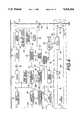
- FIG. 4is a schematic block diagram of an adaptive sequential controller for controlling the closure of a circuit breaker or switch in accordance with the present invention
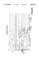
- FIGS. 5A and 5Bare an electrical schematic diagram of an environmental compensation circuit, the adaptive adjustment circuit, and a phase shift comparator of the adaptive sequential controller;
- FIG. 6Ais a graph illustrating the various signal waveforms used in the adaptive sequential controller for determining a compensation to control the closing of a circuit breaker to minimize transients;
- FIG. 6Bis a graph illustrating the signal waveforms used in the adaptive sequential controller after it is adjusted to use the compensation from FIG. 6A, thereby eliminating transients when the circuit breaker closes;
- FIG. 7is a schematic block diagram of the adaptive sequential controller used for minimizing current transients when opening a circuit breaker
- FIG. 8Ais a graph illustrating signal waveforms used in the adaptive sequential controller for determining a compensation for controlling the opening of a circuit breaker to minimize transients
- FIG. 8Bis a graph illustrating signal waveforms used in the adaptive sequential controller after it is adjusted to use the compensation from FIG. 8A, thereby eliminating transients when opening a circuit breaker;
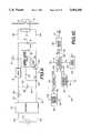
- FIG. 9is a schematic block diagram of an alternative constant current circuit for driving a circuit breaker solenoid using an AC source
- FIG. 10is a schematic block diagram of a feedback circuit to control and regulate the current supplied to activate a circuit breaker solenoid
- FIG. 11is a graph showing several waveforms over time of signals used in regulating the current that activates a circuit breaker solenoid.
- FIG. 12is a schematic block diagram of another embodiment for a DC constant current circuit used to control and drive the circuit breaker solenoid.
- a graph 10illustrates the voltage transients that can be developed if a circuit breaker or switch on a high-voltage line connected to a capacitor bank is closed when the line voltage is substantially different than zero.
- the switch or circuit breakeris activated by an activation voltage signal V a applied to its solenoid at a time t 0 , indicated by reference numeral 12.
- the time interval during which the circuit breaker activation voltage V a is suppliedis indicated by a dotted band 14 on graph 10.
- the inherent time delay, ⁇ , of the circuit breaker or switch to respond to the activation voltageelapses at a time t 1 , indicated by a reference numeral 16, at which point the switch or circuit breaker closes, applying a substantially non-zero line voltage to the capacitor bank load.
- the sudden application of a near peak line voltage to the capacitor bankcauses a voltage transient and ringing to be developed across the capacitor bank.
- This transienthas a maximum voltage amplitude 18, which can be much greater than the normal voltage for which the capacitor bank is rated.
- a generally normal sinusoidal voltage waveform 20is evident. However, it is clearly desirable to avoid producing transients with an unacceptable maximum voltage amplitude 18.
- a more purely sinusoidal waveformcan be achieved by activating the switch or circuit breaker closing mechanism at a time ⁇ seconds prior to the zero crossing of the line voltage.
- FIG. 2shows a graph 22 wherein the benefit of adaptively compensating for a ⁇ ', changed relative to ⁇ , is illustrated.
- a switch activation voltage V ais applied at t 0 ', as indicated by reference numeral 24.
- the activation voltage V a indicated by dotted band 14is applied over the indicated time interval, so that after the delay ⁇ ', the switch closes at a time t 1 ', which is identified by a reference numeral 26.
- a normal sinusoidal voltage 20without transients, is immediately applied across the capacitor bank. Elimination of the transient that was produced in the example illustrated by graph 10 is thus one of the most significant benefits derived from the adaptive operation of the circuit breaker or switch made possible by the present invention.
- the duration of the changemust be determined by monitoring either the line voltage or the current flowing in the line to detect any transients that occurred when the circuit breaker or switch is activated.
- the reference selectedis the voltage waveform.
- a square wave synchronizing signal 34(as shown in FIG.
- Line voltage transient signal 40defines when a transient occurred (which should only happen if the value of ⁇ for the circuit breaker or switch changed from the last value used, or if the value was previously set to the wrong duration). Line voltage transient signal 40 thus indicates the actual closing time of the circuit breaker or switch and also indicates that the value of ⁇ used in triggering the circuit breaker or switch should be adaptively changed to eliminate a transient on subsequent operations of the circuit breaker or switch.
- An output signal 42 from transient detector 30includes an indication of the error, ⁇ , by which ⁇ must be adjusted to compensate for any change in the reaction time of the switch or circuit breaker.
- This errorwhich may be either a positive or negative value, is determined with respect to one of pulses 44a, which occur on the rising edge of synchronizing signal 34, or one of pulses 44b, which occur on the trailing edge of synchronizing signal 34, 180° after each pulse 44a.
- the time between either pulse 44a or pulse 44b and a transient pulse 46determines the error, ⁇ .
- Transient pulse 46is developed by differentiating a voltage signal to enlarge the relatively high frequency transient.
- the same arrangementcan be applied for determining the circuit breaker or switch timing error with respect to opening of the circuit breaker or switch, which may be different than the timing error for closing it; opening of a circuit breaker or switch should occur only when the current flowing through the device is zero to substantially eliminate transients and restrikes. Closing the circuit breaker or switch when the voltage is substantially different than zero, or opening the circuit breaker or switch when the current through it is substantially different than zero typically produces a transient, indicating that adaptive compensation, due to changes in the value of ⁇ , are required during the next such operation of the device in order to substantially eliminate such transients.
- the transientscan be determined by monitoring either the current or voltage on the power line, so can the reference for determining when to open such a device be developed either directly, by monitoring the zero crossing of current, or indirectly, by monitoring the zero crossing of voltage on the line and the phase angle between current and voltage so that the zero crossing of current is determined. If the phase angle between the current and voltage is known (assuming it is relatively constant) or if it is measured, the zero crossing of current is readily determined by applying the phase angle to the zero crossing of voltage.
- FIG. 4a block diagram of a first embodiment of adaptive sequential controller 50 that is used for controlling the opening or closing of a circuit breaker 52 in accordance with the present invention is shown.
- One adaptive sequential controllers 50is used for opening circuit breaker 52, and another adaptive sequential controllers 50 is used for closing the circuit breaker to accommodate different reaction times for the opening and closing sequence.
- Circuit breaker 52is installed on a distribution line 48 to control current flow to a load (not shown--disposed below or down line of the circuit breaker) and is illustrated as a single-phase device, but may also represent the circuit breaker for one phase of a multi-phase circuit breaker, each phase of which is separately controlled by a different solenoid coil 56.
- two separate adaptive sequential controllers 50are required for each phase of the circuit breaker, one for controlling opening of the circuit breaker and one for controlling closing of the circuit breaker, or a total of six adaptive sequential controllers 50. Since the circuit breaker section for each phase is then separately controlled to compensate for the operating parameters of the circuit breaker section in opening or closing, differences in the angle between the phase voltages will not adversely affect the adaptive sequential controller operation.
- adaptive sequential controller 50On power lines with substantially balanced loads, e.g., transmission lines, it is possible to use adaptive sequential controller 50 to control opening or closing of all three phase sections of the breaker by supplying an appropriate 120 degree offset in the control signal for the solenoid that actuates each of the three different phases of the circuit breaker--either to open or close. The operation of the adaptive sequential controller is then referenced to only one phase, but controls all three.
- Circuit breaker 52is opened or closed each time that an activation voltage is applied across solenoid 56, through leads 58a and 58b.
- Lead 58aconnects directly to the negative terminal of a DC source 60 that is remotely located, for example, in a substation control room (not shown).
- Lead 58bis connected to a relay 62, which is normally open.
- Current from DC source 60flows via a lead 64 through relay 62, when it is closed, into lead 58b.
- Lead 64is connected to the cathode of a silicon controlled rectifier (SCR) 66 and, when the SCR is triggered to a conductive state in response to a signal V12 from SCR triggering circuit 110 conveyed on a lead 79, carries current from DC source 60 to relay 62.
- SCRsilicon controlled rectifier
- SCR 66is coupled to the positive terminal of the DC source through a lead 68.
- a suitable predetermined delayis provided by SCR triggering circuit 110 in producing signals V12 for each of the other phases. For example, for a three phase power line 48, a predefined 120 degree delay would be provided by SCR triggering circuit 110 for each successive signal V12 used to control a corresponding SCR 66 on the other phases (not shown).
- Each circuit breaker section of the multi-phase circuit breakeris then actuated in sequence in response to the adaptive sequential controller, based on the zero voltage crossing of only one phase for closing, and based on the phase angle/zero current crossing for that one phase when opening the multi-phase circuit breaker.
- relay 62In order for solenoid 56 in circuit breaker 52 to be energized to open or close the circuit breaker, relay 62 must be closed and SCR 66 must be activated to convey current from DC source 60.
- An external switching commandapplied over a lead 75 through a relay drive 69 and a lead 71, energizes relay 62, which energizes solenoid 56 to initiate opening or closing of contacts 54 in circuit breaker 52.
- Delay circuit 73which also receives the external switching command via lead 75, delays application of the switching command signal via a lead 77 to SCR triggering circuit 110 for a few milliseconds to ensure that relay 62 has closed before SCR 66 is turned on.
- any fault in SCR 66(causing it to conduct current) is precluded from actuating circuit breaker 52 at times other than in response to the external switching command signal.
- An alternating current (AC) line voltage signal V1120 volts
- V1120 volts
- the power supplyconverts the relatively low voltage AC to appropriate DC voltages that are used to energize the electronic circuitry comprising adaptive sequential controller 50.
- Filter 76removes substantially all of the harmonic distortion on the periodic AC signal, producing a substantially pure sinusoidal signal on a line 78, at the output of the filter.
- each of the signals used by adaptive sequential controller 50 during the process of determining a change in the value of ⁇ that should be applied to compensate for changes in the operating time of the circuit breakerare shown in FIG. 6A.
- the signalsare identified as V1 through V13 and in addition, include reference numbers identifying the specific pulses or waveforms.
- line voltage signal V1includes distorted peaks 202 prior to the removal of such distortion by filter 76, yielding a filtered line voltage signal V2 having an undistorted waveform 204.
- the signal output from filter 76is used by a timing circuit 80 that detects each zero crossing of the periodically varying sinusoidal waveform and produces a corresponding synchronizing signal V3, comprising a square wave 206 that has rising and falling edges corresponding to the time when filtered line voltage signal V2 crosses zero.
- the phase-locked loop circuitproduces a signal V4 comprising relatively high frequency pulses 208 (high frequency compared to the line frequency) that are phase-locked to 50/60 Hz square wave signal 206.
- the purpose of producing high frequency pulses 208is to improve the resolution and definition with which the required adaptive adjustment in ⁇ is determined.
- signal V4has a frequency 1,024 times the frequency of square wave signal 206, e.g., 61.44 KHz for a 60 Hz square wave signal.
- square wave signal 206may be a 50 Hz signal, corresponding to the AC line frequency used by many utilities throughout the world, some other frequency that is derived from the line frequency.
- signal V4can have a substantially different frequency than that used in the preferred embodiment, to achieve other levels of resolution.
- Differential circuit 86processes square wave signal 206, producing a positive going, zero-crossing voltage signal V5 comprising successive pulses 210 that are coincident with each a positive going, zero-crossing voltage (rising edge) of square wave 206.
- a pulse 210is produced at the beginning of each cycle of square wave 206 to serve as a reference point for determining the actual time that circuit breaker 52 closes (and the required correction or adaptive change to apply, based upon the time at which any transients are produced).
- Transientscan be detected using the potential signal produced by potential transformer 70.
- a current transformer or potential transformerdown line from circuit breaker 52 can be used for this purpose.
- the secondary of a current transformer 88 that monitors current flow through distribution line 48is used to provide a current signal indicative of transients produced by closure of circuit breaker 52 at other than a zero potential on distribution line 48.
- Lines 72 and 90are connected to a phase angle monitor 89 that measures the phase angle between current and voltage on distribution line 48 to provide a phase angle signal carried on a line 91 that is connected to differential circuit 86.
- the phase angle signalis used in connection with adaptive control of circuit breaker 52 when it is to be opened, by enabling the zero crossing of current to be determined by reference to the zero crossing of voltage on the distribution line, as explained in greater detail below. If the load controlled by circuit breaker 52 represents a relatively constant phase angle, a phase angle control (not separately shown) provided in differential circuit 86 can be manually adjusted to the constant phase angle setting, producing a phase angle signal corresponding to the known phase angle between current and voltage on distribution line 48.
- phase angle signalis combined with synchronizing signal V3 to produce signal V5, which is used to determine an appropriate time for activating the circuit breaker to open, coincident with the expected zero crossing of current (but actually referenced to the monitored zero crossing of voltage).
- Signal V5is also input to adaptive adjustment circuit 102.
- a signal V6 produced by the secondary winding of current transformer 88includes a transient in the first few ms of a current waveform signal 230 if circuit breaker 52 closes at other than the zero potential, indicating that a change in the value used for ⁇ is required to compensate for changes in the operating time of circuit breaker 52. If circuit breaker 52 closes at a zero potential on distribution line 48, no transients are produced.
- Transient detector 92responds to any high frequency transient that is produced (during a short time window, when it is appropriate to determine if adaptive compensation of ⁇ is required), producing a signal V7 comprising a square pulse 234 having a rising edge that is coincident with the inception of any such transient and lasting about three cycles of the line frequency.
- Signal V7is conveyed from transient detector 92 over a line 94 to a phase shift comparator 96.
- signal V7can be produced in response to any transients monitored using potential transformer 70 that are conveyed to transient detector 92 over a line 90' that is connected to the secondary of potential transformer 70.
- Phase shift comparator 96determines the relative phase angle (or time interval) between a rising edge 228 of a pulse 226, which indicates closure of circuit breaker 52, and the next successive pulse 210 produced by differential circuit 86.
- a signal V8 comprising a pulse 236is thus output from phase shift comparator 96 over a line 100, which is coupled to the input of an adaptive adjustment circuit 102.
- the duration between the rising and falling edges of pulse 236corresponds to a time, ⁇ adp , which represents a required adjustment to the previous value used for compensating changes in the delay time of circuit breaker 52 that should be applied when circuit breaker 52 is next actuated.
- An initial or previously determined compensation time, ⁇ 1in connection with the value ⁇ adp , is used by adaptive adjustment circuit 102 to determine the new compensation time ⁇ 2 that will next be applied to substantially eliminate any transients on distribution line 48.
- Adaptive adjustment circuit 102determines the appropriate time to activate circuit breaker 52, compensated for changes in its response time, so as to substantially eliminate transients.
- This compensated timeis output by adaptive adjustment circuit 102 on a line 106 that is coupled to an environmental compensation circuit 109.
- the environmental compensation circuitmodifies the compensated time as appropriate to offset changes in the response time of circuit breaker 52 caused by ambient temperature, barometric pressure, and humidity.
- Environmental compensation circuit 109produces a signal V9 that is conveyed on a line 108 to SCR triggering circuit 110.
- Signal V9is a sequence of short pulses at spaced intervals that establish the rising edge of a gating signal V12.
- Signal V12is applied over a line 79 to the gate of SCR 66 to trigger it into a conductive state so that the SCR will carry current to energize solenoid 56 and actuate circuit breaker 52.
- signal V9controls the timing for the rising edge of gating signal V12
- the gating signalis only produced by SCR triggering circuit 110 upon receipt of a signal V11, which is conveyed from delay circuit 73, via a line 77, in response to external switching command signal V10.
- External switching command signal V10is supplied from an external source each time that circuit breaker 52 is to be actuated and thus controls the circuit breaker, subject to the appropriate time delay dictated by signal V9.
- external switching command signal V10is also supplied via line 75 to relay drive circuit 69, which produces the signal to activate relay 62, closing it to enable activation of circuit breaker 52 in response to switching command signal V10.
- Relay 62provides fail-safe control of circuit breaker 52, preventing it from being activated, for example, should SCR 66 fail in a short circuit condition.
- Delay circuit 73appropriately delays the external switching command signal V10, also applied to SCR triggering circuit 110, to provide sufficient time for relay drive 69 to close relay 62. The delay provided by delay circuit 73 prevents the SCR from attempting to actuate the circuit breaker before relay 62 has closed.
- FIG. 5Balso illustrates the principal component of phase shift comparator 96, i.e., a flip flop 120 having its reset terminal connected to line 98 to receive signal V5 and its set terminal connected to a line 94 to receive signal V7.
- the phase shift comparatorproduces signal V8 that is conveyed by line 100 to one input of a NAND gate 122.
- the other input of NAND gate 122is connected to a line 104 to receive signal V4.
- the output of NAND gate 122is connected by a line 124 to a clock terminal of a binary counter 126.
- Binary counter 126accumulates a binary count of the high frequency clock pulses comprising signal V4 during pulse 236, a time interval equal to ⁇ adp . However, the count accumulated by binary counter 126 is cumulative, representing the total of the prior value of the compensation time, ⁇ 1 , and an appropriate adaptive correction. If the total exceeds a period, T, (the period of the line frequency), then the accumulated count in the binary counter starts over.
- the accumulated countis conveyed as a binary value (P1 through P10) on lines 130, each binary digit being input to a different one of ten bilateral switches 132a through 132j. The other input of each bilateral switch is connected by a line 146 to a different switch 142, identified as SQ1 through SQ10.
- switches 142are connected to +15 VDC through a line 144.
- a set of resistors 136are each connected in parallel with a corresponding number of capacitors 138 between a grounded line 140 and lines 146.
- Switches 142enable manually setting the compensation time for circuit breaker 52. By selectively closing specific switches 142, an operator selects a preset binary count (U1 through U10) that serves as an alternative to use of binary counter 126, which adaptively determines the compensation time. The provision for manual entry of a compensation time is included to cover situations in which automatic adaptive compensation is not desired.
- Bilateral switches 132select either the adaptively determined count (P1 through P10) from binary counter 126 or the manually preset count (U1 through U10) from switches 142 in response to a control signal that is input to each bilateral switch over a line 121.
- the control signal that selects the cumulative count from binary counter 126is applied at the output of an inverter gate 119 when a switch 112 is manually closed by an operator.
- One side of switch 112is connected to a resistor 116 and a capacitor 118, which are connected in parallel to ground, and the other side of switch 112 is connected to one end of a resistor 114.
- the other end of resistor 114is connected to +15 VDC through a lead 128.
- switch 112When switch 112 is closed, a logic level one is input to inverter gate 119; a resulting logic level zero on the output of inverter gate 119 causes bilateral switches 132 to select the inputs that are connected to receive the binary count P1 through P10 on binary counter 126. If switch 112 is opened, bilateral switches 132 respond to a resulting logic level one on line 121 by selecting the binary count U1 through U10, which is manually preset by closure of certain of switches 142.
- the binary count selected by bilateral switches 132is output on lines 148, each of which is separately connected to one input of a different exclusive NOR (XNOR) gate 150a through 150j.
- the other input of each XNOR gateis connected to a different one of ten terminals Q1 through Q10 on a binary counter 152 by lines 154.
- the clock terminal of binary counter 152is connected to line 104 to receive signal V4, and the reset terminal is connected to line 98 to receive signal V5. Consequently, binary counter 152 is reset with each rising edge of signal V5 so that it accumulates the relatively high frequency pulses comprising signal V4.
- Each XNOR gate 150produces a logic level one at its output only when both of its inputs are at the same logic level, i.e., the output signals from all of the XNOR gates are at logic level one only when the count from bilateral switches 132 equals the count from binary counter 152.
- the count accumulated in binary counter 126determines the adaptively compensated time interval for use in controlling subsequent operations of circuit breaker 52
- the count accumulated by binary counter 152provides a time reference for initiating operation of the circuit breaker with the adaptive compensation time interval developed by binary counter 126.
- the output signals from XNOR gates 150a through 150dare applied to the four input terminals of a quad input NAND gate 158 over lines 156.
- the output signals of XNOR gates 150e through 150hare applied to the four input terminals of a quad input NAND gate 162 over lines 160.
- the outputs of XNOR gates 150i and 150jare separately applied to two pairs of input terminals of a quad NAND gate 166 over lines 164a and 164b, respectively.
- the output signals of NAND gates 158, 162, and 166are at a logic level zero only when all input terminals of the NAND gates are at a logic level one, i.e., when only the accumulated count of binary counters 126 and 152 are equal.
- the output terminals of the three NAND gatesare separately applied to the input terminals of a NOR gate 170 over lines 168. It should be apparent that the output signal of NOR gate 170 is a logic level one only when all of its input terminals are at logic level zero.
- the signal output from NOR gate 170is conveyed on line 106 to a central processing unit (CPU) 172 in environmental compensation circuit 109.
- the environmental compensation circuitcomprises an ambient temperature sensor 174, a humidity sensor 176, and a barometric pressure sensor 178, all of which are connected by lines 180 to three inputs of a multiplexer (MUX) 182.
- MUX 182sequentially selects each of the ambient temperature, humidity, and pressure sensors in turn to provide an input over a line 184, to an analog-to-digital (A-D) converter 186 in response to a control signal supplied from CPU 172 over a line 188.
- the selected input parameteri.e., ambient temperature, humidity, or pressure, is convened to a digital value by A-D converter 186 and input to CPU 172 over a line 198.
- CPU 172responds to a program stored in a read only memory (ROM) 190 in carrying out the environmental parameter compensation of the signal output from NOR gate 170. Specifically, it uses each of the environmental parameters to determine an entry point into a look-up table stored in ROM 190, specifying the address of a value stored therein over address lines 196. The value from the table is returned to the CPU over data lines 194. This value is used to adjust the time interval between successive pulses that are produced by CPU 172 as a function of the signal from NOR gate 170, thereby producing pulses 238, which comprise signal V9.
- ROMread only memory
- the values in the look-up tableare empirically determined for a specific manufacturer and model of circuit breaker 52, based on the changes in the response time of the circuit breaker due to ambient temperature, humidity, and barometric pressure. Accordingly, signal V9 is adaptively adjusted not only to compensate for changes in the circuit breaker due to aging and use, but also for changes due to environmental conditions.
- Signal V9is input to SCR triggering circuit 110 over line 108 to determine when the rising edge of signal V12 occurs. From the previous discussion, it will be recalled that signal V12 gates SCR 66 into a conductive state. In addition to providing signal V12 to SCR 66, SCR triggering circuit 110 supplies signal V12, via a line 61, to a delay circuit 81. Delay circuit 81 develops a delay, ⁇ V13 , between the rising edge of signal V12 (or pulse 238 comprising signal V9) and the rising edge of time interval ⁇ T that defines a window during which any transient developed on distribution line 48 as a result of the operation of circuit breaker 52 is detected by transient detector 92.
- a pulse 232 extending over the time internal ⁇ Tis supplied as an enabling signal V13 to transient detector 92, allowing it to respond to transients only during the time when such transients are likely to be developed, for example, as a result of the closure of circuit breaker 52 at other than a non-zero crossing point for the voltage on distribution line 48.
- transient signal V6is developed if circuit breaker 52 closes, when the closure occurred at other than a zero crossing of the voltage on distribution line 48, e.g., due to changes in the response time of the circuit breaker as a result of aging.
- transient detector 92produces signal V7 comprising a pulse 234, to indicate the time at which the transient started, and lasting for about three cycles of the line frequency. Since any such transient starts when the circuit breaker closes at other than a zero voltage crossing, signal V7 also indicates the actual time at which circuit breaker 52 closed.
- phase shift comparator 96determines pulse 236, which corresponds to the adaptive time compensation, ⁇ adp .
- This adaptive time compensationis supplied as signal V8 to adaptive adjustment circuit 102, which adjusts the timing for signal V9 as explained above.
- the adjustment in the timing between the two successive pulses 238 comprising signal V9(a change caused by including ⁇ adp ) is evident in the interval with ⁇ 2 in FIG. 6A. Following the ⁇ adp adjustment, the interval between successive pulses 238 remains constant, as indicated in FIG. 6B, until another adjustment is needed.
- circuit breaker 52in response to this adaptive adjustment of the timing for initiating signal V12 is illustrated in FIG. 6B.
- circuit breaker 52 as controlled by the present inventionis closed as the voltage on distribution line 48 crosses zero. Consequently, signal V6 does not include any significant transient; instead, there is almost no variation between the first cycle of current waveform 230 and subsequent cycles. Since closure of circuit breaker 52 is coincident with the time that the voltage on distribution line 48 crosses zero and no transient is produced, the value of ⁇ 2 remains unchanged the next time that the circuit breaker is closed, if there is no change in circuit breaker operating time due to ambient conditions or aging.
- Adaptive adjustment circuit 102is designed to apply the appropriate equation to determine ⁇ 2 , based upon these criteria.
- FIG. 7Details of the present invention as applied in a second embodiment to adaptively controlling only the opening of circuit breaker 52 so as to substantially eliminate transients are shown generally in FIG. 7, with respect to an adaptive sequential controller identified by reference numeral 50'.
- potential transformer 70does not supply a signal V1 to filter 76 or transient detector 92, and, in addition, phase angle monitor 89 is not used.
- current transformer 88supplies signal V6 over line 90 to filter 76. Harmonic distortion present on signal V6 is substantially reduced by filter 76, and a filtered current signal is supplied as signal V2 over line 78 to timing circuit 80.
- timing circuit 80At each zero crossing of the filtered current signal V2, timing circuit 80 produces square wave pulses 206, comprising signal V3.
- All other components of adaptive sequential controller 50' shown in block diagram FIG. 7operate as described with regard to the like numbered components in FIG. 4, subject to the caveat that the adaptive compensation is developed to compensate for the response time of circuit breaker 52 after a signal is applied to solenoid 56 to open the circuit breaker, which may be different than the response time required for the circuit breaker to close after it is actuated.
- the adaptive sequential controlleradjusts the time at which the solenoid is actuated so that the next time it is activated, circuit breaker opens when the current through distribution line 48 is passing through zero.
- FIGS. 8A and 8Billustrate the various signals V2 through V13 developed by the components in FIG. 7 to provide adaptive control of circuit breaker 52 to substantially eliminate transients on distribution line 48 that would otherwise be caused by opening the circuit breaker when the current in distribution line 48 is not equal to zero.
- FIG. 8Athe adaptive operation of the present invention is shown, illustrating how each of the signals developed determine a correction ⁇ adp ', to compensate for a change in the response time of the circuit breaker as it opens.
- Adaptive sequential controller 50'can also be used to control one phase of multi-phase breaker on an imbalanced load power line or to control the opening of a plurality of phases of a multi-phase breaker on a balanced load power line.
- Phase shift comparator 96determines that an adaptive time interval, ⁇ adp ', corresponding to the width of pulse 236 on signal V8 needs to be made so that the next time circuit breaker 52 opens, the default delay is increased by ⁇ adp '. In FIG. 8B, this adjustment is made, resulting in circuit breaker 52 opening at substantially the point where current through distribution line 48 crosses through zero with a positive slope. As a result, transients on distribution line 48 are substantially eliminated.
- circuit breaker 52can be adaptively controlled to substantially eliminate transients on distribution line 48 caused by opening the circuit breaker, even though the zero crossing of current is not directly monitored. Instead, the zero crossing point of the voltage on distribution line 48 is monitored and the zero crossing of current is indirectly determined by using phase angle monitor 89.
- Phase angle monitor 89produces a signal that is indicative of the phase angle between voltage and current on distribution line 48, and the signal is input to differential circuit 86 over line 91.
- differential circuit 86combines a time interval corresponding to the phase angle with the time at which the rising edge of signal V3 occurs (indicative of a positive-going slope voltage zero crossing), producing signal V5.
- Signal V5thus comprises pulses 210, each of which occur at the positive-going zero crossing of the current on distribution line 48.
- Monitoring the phase angle between voltage and currentpermits reference to the voltage to determine zero crossing times for the current on the distribution line.
- phase angle control in differential circuit 86produces a signal indicative of the constant phase angle, just like the signal produced by phase angle monitor 89. This signal is applied to the voltage zero crossing reference of signal V3 to derive a timing reference to current zero crossing that comprises signal V5.
- FIGS. 4 and 7a circuit breaker activation circuit 59 is illustrated (within the dash lines at the bottom of the figures).
- FIG. 9shows an alternative activation circuit indicated generally by reference numeral 59' that can be used in either embodiment of the adaptive sequential controller.
- the activation circuit shown in FIG. 9omits DC source 60, replacing it with an AC source 250, which is connected by lines 252 to a full wave rectifier 254.
- AC source 250is subject to line variations that may cause changes in the response time of circuit breaker 52, which are not readily compensated, because they tend to vary unpredictably.
- activation circuit 59'regulates the current flow supplied solenoid 56 of circuit breaker 52, thereby compensating for variations in the voltage level of AC source 250.
- Activation circuit 59'also includes a diode 57 that is connected in parallel with solenoid 56, the cathode of the diode being coupled to relay 62 via lead 58b.
- a line 255connects the output of full wave rectifier 254 to one end of a resistor 256, the other end of which is connected to the collector of an insulated gate bipolar transistor (IGBT) 262 by a lead 258.
- Lead 258also connects to a capacitor 260, the opposite end of which is connected to the other output of rectifier 254 through a lead 264.
- the emitter of IGBT 262is connected through a lead 266 to relay 62, and its base is connected through a line 274 to a current source control circuit (CSCC) 272.
- CSCC 272receives a signal indicative of the current flow through solenoid 56 of circuit breaker 52 that is conveyed from a current sensing circuit 268 through a line 282.
- CSCC 272is coupled to line 79 to receive signal V12, which is supplied to control activation of circuit breaker 52. In connection with IGBT 262, CSCC 272 thus regulates the current flow through solenoid 56 when signal V12 conveys pulse 220, causing the CSCC to bias the base of IGBT 262 so that the device conducts current. Regulated current flows through the relay contacts in relay 62, through solenoid 56, and returns through line 264 to full wave rectifier 254.
- IGBT 262is turned on, the current flowing through lead 266, i CT , equals the current through solenoid 56, i CB , and the current through diode 57, i D , is zero.
- IGBT 262is turned off, i CT is zero, and I CB equals i D .
- FIGS. 10 and 11Details of CSCC 272 are shown in FIGS. 10 and 11.
- Current sensing circuit 268produces an output voltage (V CT1 ) proportional to the current (i CT ) of IGBT 262 that is input to an amplifier 284 over a line 282.
- Amplifier 284increases the amplitude of the signal V CT1 by a fixed gain, producing an output signal (V CT2 ) that is conveyed on a line 286 to a voltage comparator 288.
- the other input of voltage comparator 288is connected through a line 292 to a reference waveform generator 290 that produces a reference voltage waveform (V h ) when enabled by signal V12.
- voltage comparator 288compares the signal indicative of current flow through IGBT 262 to the desired reference voltage source level V h , and receives a pulse signal, V d , from a delay circuit 295 through a lead 297, producing an output signal V dr that is conveyed by a line 294 to a driving circuit 296.
- the output of driving circuit 296is supplied to the base of IGBT 262 to control the conductivity of the device, and thus to regulate the current flow through solenoid 56.
- reference waveform generator 290produces a reference voltage V h , and voltage comparator 288 sets its output V dr to a high level.
- the voltage across storage capacitor 260is applied to the two ends of solenoid 56 through the conduction of both IGBT 262 and relay 62.
- the current through solenoid 56(i CB ) increases, as also does V CT1 and V CT2 .
- IGBT 262is on, its current i CT is equal to the current i CB through the solenoid.
- V CT2is equal to V h , and voltage comparator 288 sets it output V dr to a low level, which turns IGBT 262 off.
- the current i CT through the IGBTbecomes zero, and so do V CT1 and V CT2 .
- the solenoid current i CBflows through freewheeling diode 57 and decays.
- the failing edge of V dralso enables delay circuit 295.
- the delay circuitAfter a fixed time ( ⁇ CS ), at a time t 12 , the delay circuit generates a pulse V d , which makes voltage comparator 288 set its output voltage V dr to a high level. A new period begins.
- the current flowing through solenoid 56is thus substantially regulated to a fixed level waveform as shown in FIG. 11.
- a still further embodiment of the activation circuitis generally indicated by reference number 59".
- a DC source 60'is used that is somewhat less stable than DC source 60 in corresponding circuit 59 and therefore, requires regulation to ensure that the current does not fluctuate, causing variations in the response time of circuit breaker 52.
- DC source 60'is connected on the positive side through a line 255' to resistor 256 and on the negative side through a line 264' to capacitor 260 and solenoid 56, All other components of the embodiment shown in FIG. 12 are identical to solenoid control circuit 59', which was discussed above with respect to FIG. 10.
- CSCC 272monitors the current flowing through solenoid 56 to develop a positive feedback signal that is used to control the current flow, thereby regulating it to a relatively constant level.
- adaptive sequential controllers 50/50'provide a significant improvement over prior art devices used to control circuit breakers and other types of switches.
- potential transformer 70For application of the device where the phase angle of the distribution line is relatively constant, it is possible to use potential transformer 70 to provide the timing and reference signals and for detecting transients, eliminating the need for current transformer 88, thereby substantially reducing the cost of a sequential adaptive controller used in controlling both opening and closing of circuit breaker 52.
- phase angle monitor 89can be used to determine the phase angle between current and voltage on distribution line 48, thereby enabling the timing and reference signal developed in response to the voltage to be used in controlling the opening of the circuit breaker by deriving the current zero crossing reference as a function of the phase angle.
Landscapes
- Engineering & Computer Science (AREA)
- Power Engineering (AREA)
- Keying Circuit Devices (AREA)
Abstract
Description
Claims (40)
Priority Applications (2)
| Application Number | Priority Date | Filing Date | Title |
|---|---|---|---|
| US07/963,692US5361184A (en) | 1992-10-20 | 1992-10-20 | Adaptive sequential controller |
| US08/312,389US5644463A (en) | 1992-10-20 | 1994-09-26 | Adaptive sequential controller with minimum switching energy |
Applications Claiming Priority (1)
| Application Number | Priority Date | Filing Date | Title |
|---|---|---|---|
| US07/963,692US5361184A (en) | 1992-10-20 | 1992-10-20 | Adaptive sequential controller |
Related Child Applications (1)
| Application Number | Title | Priority Date | Filing Date |
|---|---|---|---|
| US08/312,389Continuation-In-PartUS5644463A (en) | 1992-10-20 | 1994-09-26 | Adaptive sequential controller with minimum switching energy |
Publications (1)
| Publication Number | Publication Date |
|---|---|
| US5361184Atrue US5361184A (en) | 1994-11-01 |
Family
ID=25507573
Family Applications (1)
| Application Number | Title | Priority Date | Filing Date |
|---|---|---|---|
| US07/963,692Expired - LifetimeUS5361184A (en) | 1992-10-20 | 1992-10-20 | Adaptive sequential controller |
Country Status (1)
| Country | Link |
|---|---|
| US (1) | US5361184A (en) |
Cited By (67)
| Publication number | Priority date | Publication date | Assignee | Title |
|---|---|---|---|---|
| US5467651A (en)* | 1992-10-23 | 1995-11-21 | Ricoh Seiki Company, Ltd. | Drive control apparatus for microsensor |
| US5578753A (en)* | 1995-05-23 | 1996-11-26 | Micro Weiss Electronics, Inc. | Humidity and/or temperature control device |
| US5629869A (en)* | 1994-04-11 | 1997-05-13 | Abb Power T&D Company | Intelligent circuit breaker providing synchronous switching and condition monitoring |
| US5734207A (en)* | 1994-05-06 | 1998-03-31 | Miklinjul Corporation | Voltage polarity memory system and fuse-switch assembly usable therewith |
| US5808851A (en)* | 1995-04-06 | 1998-09-15 | H.P.M. Industries Pty Limited | Controlled switching |
| US5875087A (en)* | 1996-08-08 | 1999-02-23 | George A. Spencer | Circuit breaker with integrated control features |
| EP0830699A4 (en)* | 1995-05-15 | 1999-04-14 | Cooper Ind Inc | Control method and device for a switchgear actuator |
| AU710866B2 (en)* | 1995-04-06 | 1999-09-30 | H.P.M. Industries Pty Limited | Controlled switching |
| US5963021A (en)* | 1998-05-11 | 1999-10-05 | Siemens Power Transmission & Distribution, Llc | Delayed contact closing apparatus and method for capacitors |
| FR2791466A1 (en)* | 1999-03-23 | 2000-09-29 | Crouzet Automatismes | Electronic command mechanism assisted electromagnet relay switching alternating current and having near zero volts nuller during closure and near zero amps nuller during opening. |
| US6291911B1 (en) | 1995-05-15 | 2001-09-18 | Cooper Industries, Inc. | Electrical switchgear with synchronous control system and actuator |
| US6331687B1 (en) | 1995-05-15 | 2001-12-18 | Cooper Industries Inc. | Control method and device for a switchgear actuator |
| WO2001097239A1 (en)* | 2000-06-16 | 2001-12-20 | Siemens Aktiengesellschaft | Method for operating an electromagnetic switching device and electromagnetic switching device |
| US6534947B2 (en)* | 2001-01-12 | 2003-03-18 | Sta-Rite Industries, Inc. | Pump controller |
| US6538347B1 (en) | 1995-05-15 | 2003-03-25 | Mcgraw-Edison Company | Electrical switchgear with synchronous control system and actuator |
| US20030212473A1 (en)* | 2002-02-25 | 2003-11-13 | General Electric Company | Processing system for a power distribution system |
| US20030212515A1 (en)* | 2002-02-25 | 2003-11-13 | General Electric Company | Data sample and transmission modules for power distribution systems |
| US20030214907A1 (en)* | 2002-02-25 | 2003-11-20 | General Electric Company | Method for communicating information bundled in digital message packets |
| US6710482B2 (en) | 2001-08-25 | 2004-03-23 | Lucas Aerospace Power Equipment Corporation | Generator |
| US20060130277A1 (en)* | 2004-12-22 | 2006-06-22 | Xerox Corporation | Hinge with tandem pivot structure motion lock and override |
| US7111195B2 (en) | 2002-02-25 | 2006-09-19 | General Electric Company | Method and system for external clock to obtain multiple synchronized redundant computers |
| US7307542B1 (en) | 2003-09-03 | 2007-12-11 | Vantage Controls, Inc. | System and method for commissioning addressable lighting systems |
| US7361853B2 (en) | 2001-02-28 | 2008-04-22 | Vantage Controls, Inc. | Button assembly with status indicator and programmable backlighting |
| US7394451B1 (en) | 2003-09-03 | 2008-07-01 | Vantage Controls, Inc. | Backlit display with motion sensor |
| US20080232005A1 (en)* | 2007-03-20 | 2008-09-25 | Kuehnle Barry W | Method for protecting an electric generator |
| US20090027824A1 (en)* | 2003-09-03 | 2009-01-29 | Vantage Controls, Inc. | Current Zero Cross Switching Relay Module Using A Voltage Monitor |
| EP1944781A3 (en)* | 2003-02-28 | 2009-04-08 | EATON Corporation | Method and apparatus to control modular asynchronous contactors |
| US7525782B1 (en)* | 2005-03-31 | 2009-04-28 | The United States Of America As Represented By The United States Department Of Energy | Adaptive protection algorithm and system |
| US7532955B2 (en) | 2002-02-25 | 2009-05-12 | General Electric Company | Distributed protection system for power distribution systems |
| US7636616B2 (en) | 2003-02-25 | 2009-12-22 | General Electric Company | Protection system for power distribution systems |
| US7672096B2 (en) | 2006-09-29 | 2010-03-02 | Rockwell Automation Technologies, Inc. | Switching apparatus and method |
| WO2010043014A1 (en) | 2008-10-13 | 2010-04-22 | Universidade Estadual De Campinas - Unicamp | Fast three-phase reclosing method in shunt reactor compensated transmission lines |
| US7747356B2 (en) | 2002-02-25 | 2010-06-29 | General Electric Company | Integrated protection, monitoring, and control system |
| US7755506B1 (en) | 2003-09-03 | 2010-07-13 | Legrand Home Systems, Inc. | Automation and theater control system |
| US20100200383A1 (en)* | 2006-09-25 | 2010-08-12 | Kabushiki Kaisha Toshiba | Switching controlgear of circuit breaker |
| US7778262B2 (en) | 2005-09-07 | 2010-08-17 | Vantage Controls, Inc. | Radio frequency multiple protocol bridge |
| US20100265630A1 (en)* | 2009-04-20 | 2010-10-21 | Jeffrey Baxter | Relay with Current Transformer |
| WO2011150975A1 (en)* | 2010-06-04 | 2011-12-08 | Abb Technology Ag | Control arrangement |
| JP2014089955A (en)* | 2012-10-30 | 2014-05-15 | Lsis Co Ltd | High-speed fault current detection circuit |
| US20140266040A1 (en)* | 2013-03-14 | 2014-09-18 | Tyco Electronics Corporation | Electric vehicle supply equipment having increased communication capabilities |
| WO2014158931A3 (en)* | 2013-03-14 | 2015-03-26 | Tyco Electronics Corporation | Electric vehicle support equipment having a smart plug with a relay control circuit |
| US9596741B2 (en) | 2012-09-05 | 2017-03-14 | Legrand North America, LLC | Dimming control including an adjustable output response |
| US10180540B2 (en) | 2014-12-15 | 2019-01-15 | CommScope Connectivity Belgium BVBA | Optical fiber clamping assembly having a plurality of cable clamp arms |
| US10250032B2 (en) | 2015-04-24 | 2019-04-02 | Vertiv Corporation | Intelligent power strip with management of bistable relays to reduce current in-rush |
| US20190181851A1 (en)* | 2017-12-08 | 2019-06-13 | Valquest Systems, Inc. | Continuously correcting capacitor switch controller system and method |
| DE102018219293A1 (en)* | 2018-11-12 | 2020-05-14 | Kaco New Energy Gmbh | Inverter |
| US10677823B2 (en) | 2017-01-06 | 2020-06-09 | Vertiv Corporation | System and method of identifying path of residual current flow through an intelligent power strip |
| CN111816496A (en)* | 2019-04-12 | 2020-10-23 | Abb瑞士股份有限公司 | Synchronous disconnection of circuit breaker |
| CN112635213A (en)* | 2020-11-27 | 2021-04-09 | 深圳曼顿科技有限公司 | Circuit breaker and opening and closing control method and device thereof |
| US20210396610A1 (en)* | 2020-06-18 | 2021-12-23 | Cirrus Logic International Semiconductor Ltd. | Baseline estimation for sensor system |
| US11507199B2 (en) | 2021-03-30 | 2022-11-22 | Cirrus Logic, Inc. | Pseudo-differential phase measurement and quality factor compensation |
| CN115461830A (en)* | 2020-04-03 | 2022-12-09 | 日立能源瑞士股份公司 | electrical switchgear |
| US11537242B2 (en) | 2018-03-29 | 2022-12-27 | Cirrus Logic, Inc. | Q-factor enhancement in resonant phase sensing of resistive-inductive-capacitive sensors |
| US11536758B2 (en) | 2019-02-26 | 2022-12-27 | Cirrus Logic, Inc. | Single-capacitor inductive sense systems |
| US11619519B2 (en) | 2021-02-08 | 2023-04-04 | Cirrus Logic, Inc. | Predictive sensor tracking optimization in multi-sensor sensing applications |
| CN116627759A (en)* | 2023-05-19 | 2023-08-22 | 北京神州安付科技股份有限公司 | Financial payment equipment circuit safety detection device |
| EP4135144A4 (en)* | 2020-06-29 | 2023-11-01 | Beijing Goldwind Science & Creation Windpower Equipment Co. Ltd. | WIND TURBINE GROUP, AND RELATED CONVERTER FILTER CAPACITOR SWITCHING CONTROL METHOD, APPARATUS AND SYSTEM |
| US11808669B2 (en) | 2021-03-29 | 2023-11-07 | Cirrus Logic Inc. | Gain and mismatch calibration for a phase detector used in an inductive sensor |
| US11821761B2 (en) | 2021-03-29 | 2023-11-21 | Cirrus Logic Inc. | Maximizing dynamic range in resonant sensing |
| US11836290B2 (en) | 2019-02-26 | 2023-12-05 | Cirrus Logic Inc. | Spread spectrum sensor scanning using resistive-inductive-capacitive sensors |
| US11835410B2 (en) | 2020-06-25 | 2023-12-05 | Cirrus Logic Inc. | Determination of resonant frequency and quality factor for a sensor system |
| US11854738B2 (en) | 2021-12-02 | 2023-12-26 | Cirrus Logic Inc. | Slew control for variable load pulse-width modulation driver and load sensing |
| US11868540B2 (en) | 2020-06-25 | 2024-01-09 | Cirrus Logic Inc. | Determination of resonant frequency and quality factor for a sensor system |
| US11979115B2 (en) | 2021-11-30 | 2024-05-07 | Cirrus Logic Inc. | Modulator feedforward compensation |
| US12130159B2 (en) | 2018-08-22 | 2024-10-29 | Cirrus Logic Inc. | Detecting and adapting to changes in a resonant phase sensing system having a resistive-inductive-capacitive sensor |
| US12295102B1 (en) | 2018-03-29 | 2025-05-06 | Cirrus Logic Inc. | Far field interference cancellation for resistive-inductive-capacitive sensors |
| US12442683B2 (en) | 2022-11-03 | 2025-10-14 | Cirrus Logic Inc. | Single-capacitor inductive sense systems |
Citations (1)
| Publication number | Priority date | Publication date | Assignee | Title |
|---|---|---|---|---|
| US5119260A (en)* | 1989-02-22 | 1992-06-02 | Siemens Aktiengesellschaft | Method for operating a circuit-breaker |
- 1992
- 1992-10-20USUS07/963,692patent/US5361184A/ennot_activeExpired - Lifetime
Patent Citations (1)
| Publication number | Priority date | Publication date | Assignee | Title |
|---|---|---|---|---|
| US5119260A (en)* | 1989-02-22 | 1992-06-02 | Siemens Aktiengesellschaft | Method for operating a circuit-breaker |
Non-Patent Citations (14)
| Title |
|---|
| A. Hohm, R. Alvinsson, U. Akesson, & O. Karlen, "Development of Controlled Switching of Reactors, Capacitors Transformers and Lines," Cigre, 1990 Session, 26 Aug.-1st Sep., 10 pp. |
| A. Hohm, R. Alvinsson, U. Akesson, & O. Karlen, Development of Controlled Switching of Reactors, Capacitors Transformers and Lines, Cigre, 1990 Session, 26 Aug. 1st Sep., 10 pp.* |
| ABB HV Switchgear, "Switchsync Relay for synchronous circuit switching" Brochure, Publ. SESWG/B 2001 E, Edition 2, 1991-06, 4 pp. |
| ABB HV Switchgear, Switchsync Relay for synchronous circuit switching Brochure, Publ. SESWG/B 2001 E, Edition 2, 1991 06, 4 pp.* |
| Joslyn Hi Voltage Corporation, VBU Faultmaster Interrupter including Zero Voltage Closing Control Instruction Manual, D.B. 750 201, May 1986, 28 pp.* |
| Joslyn Hi-Voltage Corporation, VBU Faultmaster® Interrupter including Zero Voltage Closing Control Instruction Manual, D.B. 750-201, May 1986, 28 pp. |
| N. Witteberg, Westinghouse ABB Power T & D Company publication, "Smooth Energizing of Capacitor Banks," NESA Dristb, Aug. 1989, 12pp. |
| N. Witteberg, Westinghouse ABB Power T & D Company publication, Smooth Energizing of Capacitor Banks, NESA Dristb, Aug. 1989, 12pp.* |
| R. Alexander, "Synchronous Closing Control for Shunt Capacitors," 1985 IEEE, 85 WM 221-7, pp. 1-7. |
| R. Alexander, Synchronous Closing Control for Shunt Capacitors, 1985 IEEE, 85 WM 221 7, pp. 1 7.* |
| R. Alvinsson & C. Solver, "Switching to lower transients," Transmission & Distribution, Mar. 1991, pp. 41, 43, & 45. |
| R. Alvinsson & C. Solver, Switching to lower transients, Transmission & Distribution, Mar. 1991, pp. 41, 43, & 45.* |
| R. Wolff, "Control of capacitor closing nips surges," Electrical World, Transmission/Distribution, Jan. 1, 1979, 6 pp. |
| R. Wolff, Control of capacitor closing nips surges, Electrical World, Transmission/Distribution, Jan. 1, 1979, 6 pp.* |
Cited By (117)
| Publication number | Priority date | Publication date | Assignee | Title |
|---|---|---|---|---|
| US5467651A (en)* | 1992-10-23 | 1995-11-21 | Ricoh Seiki Company, Ltd. | Drive control apparatus for microsensor |
| US5638296A (en)* | 1994-04-11 | 1997-06-10 | Abb Power T&D Company Inc. | Intelligent circuit breaker providing synchronous switching and condition monitoring |
| US5629869A (en)* | 1994-04-11 | 1997-05-13 | Abb Power T&D Company | Intelligent circuit breaker providing synchronous switching and condition monitoring |
| US5636134A (en)* | 1994-04-11 | 1997-06-03 | Abb Power T&D Company Inc. | Intelligent circuit breaker providing synchronous switching and condition monitoring |
| US5936495A (en)* | 1994-05-06 | 1999-08-10 | Miklinjul Corporation | Fuse switch |
| US5734207A (en)* | 1994-05-06 | 1998-03-31 | Miklinjul Corporation | Voltage polarity memory system and fuse-switch assembly usable therewith |
| US5808851A (en)* | 1995-04-06 | 1998-09-15 | H.P.M. Industries Pty Limited | Controlled switching |
| AU710866B2 (en)* | 1995-04-06 | 1999-09-30 | H.P.M. Industries Pty Limited | Controlled switching |
| EP0830699A4 (en)* | 1995-05-15 | 1999-04-14 | Cooper Ind Inc | Control method and device for a switchgear actuator |
| US6538347B1 (en) | 1995-05-15 | 2003-03-25 | Mcgraw-Edison Company | Electrical switchgear with synchronous control system and actuator |
| US6291911B1 (en) | 1995-05-15 | 2001-09-18 | Cooper Industries, Inc. | Electrical switchgear with synchronous control system and actuator |
| US6331687B1 (en) | 1995-05-15 | 2001-12-18 | Cooper Industries Inc. | Control method and device for a switchgear actuator |
| US5578753A (en)* | 1995-05-23 | 1996-11-26 | Micro Weiss Electronics, Inc. | Humidity and/or temperature control device |
| US5875087A (en)* | 1996-08-08 | 1999-02-23 | George A. Spencer | Circuit breaker with integrated control features |
| US5963021A (en)* | 1998-05-11 | 1999-10-05 | Siemens Power Transmission & Distribution, Llc | Delayed contact closing apparatus and method for capacitors |
| FR2791466A1 (en)* | 1999-03-23 | 2000-09-29 | Crouzet Automatismes | Electronic command mechanism assisted electromagnet relay switching alternating current and having near zero volts nuller during closure and near zero amps nuller during opening. |
| WO2001097239A1 (en)* | 2000-06-16 | 2001-12-20 | Siemens Aktiengesellschaft | Method for operating an electromagnetic switching device and electromagnetic switching device |
| US20030174457A1 (en)* | 2000-06-16 | 2003-09-18 | Reinhard Herbst | Method for operating an electromagnetic switching device and electromagnetic switching device |
| US6927959B2 (en) | 2000-06-16 | 2005-08-09 | Siemens Aktiengesellschaft | Method for operating an electromagnetic switching device and electromagnetic switching device |
| US6534947B2 (en)* | 2001-01-12 | 2003-03-18 | Sta-Rite Industries, Inc. | Pump controller |
| US7432463B2 (en) | 2001-02-28 | 2008-10-07 | Vantage Controls, Inc. | Button assembly with status indicator and programmable backlighting |
| US7432460B2 (en) | 2001-02-28 | 2008-10-07 | Vantage Controls, Inc. | Button assembly with status indicator and programmable backlighting |
| US7414210B2 (en) | 2001-02-28 | 2008-08-19 | Vantage Controls, Inc. | Button assembly with status indicator and programmable backlighting |
| US7361853B2 (en) | 2001-02-28 | 2008-04-22 | Vantage Controls, Inc. | Button assembly with status indicator and programmable backlighting |
| US6710482B2 (en) | 2001-08-25 | 2004-03-23 | Lucas Aerospace Power Equipment Corporation | Generator |
| US20030231447A1 (en)* | 2002-02-25 | 2003-12-18 | General Electric Company | Circuit breaker lockout |
| US8213144B2 (en) | 2002-02-25 | 2012-07-03 | General Electric Company | Circuit protection system |
| US20030229423A1 (en)* | 2002-02-25 | 2003-12-11 | General Electric Company | Method for power distribution system components identification, characterization and rating |
| US20040024475A1 (en)* | 2002-02-25 | 2004-02-05 | General Electric Company | Method and apparatus for optimized centralized critical control architecture for switchgear and power equipment |
| US20030225482A1 (en)* | 2002-02-25 | 2003-12-04 | General Electric Company | Method and system for conditionally triggered system data capture |
| US20040078463A1 (en)* | 2002-02-25 | 2004-04-22 | General Electric Company | Method and apparatus for minimally invasive network monitoring |
| US6892145B2 (en) | 2002-02-25 | 2005-05-10 | General Electric Company | Method and system for conditionally triggered system data capture |
| US6892115B2 (en) | 2002-02-25 | 2005-05-10 | General Electric Company | Method and apparatus for optimized centralized critical control architecture for switchgear and power equipment |
| US6909942B2 (en) | 2002-02-25 | 2005-06-21 | General Electric Company | Method for power distribution system components identification, characterization and rating |
| US20030225481A1 (en)* | 2002-02-25 | 2003-12-04 | General Electric Company | Method and apparatus for optimizing redundant critical control systems |
| US6985784B2 (en) | 2002-02-25 | 2006-01-10 | General Electric Company | Configuring a centrally controlled circuit breaker protection system |
| US6999291B2 (en) | 2002-02-25 | 2006-02-14 | General Electric Company | Method and apparatus for node electronics unit architecture |
| US7043340B2 (en) | 2002-02-25 | 2006-05-09 | General Electric Company | Protection system for power distribution systems |
| US7058481B2 (en) | 2002-02-25 | 2006-06-06 | General Electric Company | Method and apparatus for centrally-controlled electrical protection system architecture reliability improvement based on sensitivity analysis |
| US7058482B2 (en) | 2002-02-25 | 2006-06-06 | General Electric Company | Data sample and transmission modules for power distribution systems |
| US20030231440A1 (en)* | 2002-02-25 | 2003-12-18 | General Electric Company, | Circuit protection system |
| US7068612B2 (en) | 2002-02-25 | 2006-06-27 | General Electric Company | Method for communicating information bundled in digital message packets |
| US7068483B2 (en) | 2002-02-25 | 2006-06-27 | General Electric Company | Circuit breaker lockout |
| US7111195B2 (en) | 2002-02-25 | 2006-09-19 | General Electric Company | Method and system for external clock to obtain multiple synchronized redundant computers |
| US7117105B2 (en) | 2002-02-25 | 2006-10-03 | General Electric Company | Method and apparatus for ground fault protection |
| US7151329B2 (en) | 2002-02-25 | 2006-12-19 | General Electric Company | Integrated protection, monitoring, and control system |
| US7254001B2 (en) | 2002-02-25 | 2007-08-07 | General Electric Company | Circuit protection system |
| US7301738B2 (en) | 2002-02-25 | 2007-11-27 | General Electric Company | Method and apparatus for minimally invasive network monitoring |
| US7747356B2 (en) | 2002-02-25 | 2010-06-29 | General Electric Company | Integrated protection, monitoring, and control system |
| US20030216876A1 (en)* | 2002-02-25 | 2003-11-20 | General Electric Company | Method and apparatus for ground fault protection |
| US20030212473A1 (en)* | 2002-02-25 | 2003-11-13 | General Electric Company | Processing system for a power distribution system |
| US20030214907A1 (en)* | 2002-02-25 | 2003-11-20 | General Electric Company | Method for communicating information bundled in digital message packets |
| US7532955B2 (en) | 2002-02-25 | 2009-05-12 | General Electric Company | Distributed protection system for power distribution systems |
| US20030212515A1 (en)* | 2002-02-25 | 2003-11-13 | General Electric Company | Data sample and transmission modules for power distribution systems |
| US7636616B2 (en) | 2003-02-25 | 2009-12-22 | General Electric Company | Protection system for power distribution systems |
| EP1944781A3 (en)* | 2003-02-28 | 2009-04-08 | EATON Corporation | Method and apparatus to control modular asynchronous contactors |
| US20090027824A1 (en)* | 2003-09-03 | 2009-01-29 | Vantage Controls, Inc. | Current Zero Cross Switching Relay Module Using A Voltage Monitor |
| US7755506B1 (en) | 2003-09-03 | 2010-07-13 | Legrand Home Systems, Inc. | Automation and theater control system |
| US8154841B2 (en)* | 2003-09-03 | 2012-04-10 | Legrand Home Systems, Inc. | Current zero cross switching relay module using a voltage monitor |
| US7394451B1 (en) | 2003-09-03 | 2008-07-01 | Vantage Controls, Inc. | Backlit display with motion sensor |
| US7307542B1 (en) | 2003-09-03 | 2007-12-11 | Vantage Controls, Inc. | System and method for commissioning addressable lighting systems |
| US7418766B2 (en)* | 2004-12-22 | 2008-09-02 | Xerox Corporation | Hinge with tandem pivot structure motion lock and override |
| US20060130277A1 (en)* | 2004-12-22 | 2006-06-22 | Xerox Corporation | Hinge with tandem pivot structure motion lock and override |
| US7525782B1 (en)* | 2005-03-31 | 2009-04-28 | The United States Of America As Represented By The United States Department Of Energy | Adaptive protection algorithm and system |
| US7778262B2 (en) | 2005-09-07 | 2010-08-17 | Vantage Controls, Inc. | Radio frequency multiple protocol bridge |
| US20100200383A1 (en)* | 2006-09-25 | 2010-08-12 | Kabushiki Kaisha Toshiba | Switching controlgear of circuit breaker |
| US8212423B2 (en)* | 2006-09-25 | 2012-07-03 | Kabushiki Kaisha Toshiba | Switching controlgear of circuit breaker |
| US7672096B2 (en) | 2006-09-29 | 2010-03-02 | Rockwell Automation Technologies, Inc. | Switching apparatus and method |
| US20080232005A1 (en)* | 2007-03-20 | 2008-09-25 | Kuehnle Barry W | Method for protecting an electric generator |
| US7453674B2 (en)* | 2007-03-20 | 2008-11-18 | Battelle Energy Alliance, Llc | Method for protecting an electric generator |
| WO2010043014A1 (en) | 2008-10-13 | 2010-04-22 | Universidade Estadual De Campinas - Unicamp | Fast three-phase reclosing method in shunt reactor compensated transmission lines |
| EP2346132A4 (en)* | 2008-10-13 | 2013-12-04 | Unicamp | METHOD FOR QUICK TRIPOLAR REINTEGRATION IN TRANSMISSION LINES WITH REACTIVE DISPENSER COMPENSATION |
| US8169762B2 (en) | 2009-04-20 | 2012-05-01 | Energy Safe Technologies, Inc. | Relay with current transformer |
| US20100265630A1 (en)* | 2009-04-20 | 2010-10-21 | Jeffrey Baxter | Relay with Current Transformer |
| WO2011150975A1 (en)* | 2010-06-04 | 2011-12-08 | Abb Technology Ag | Control arrangement |
| US8817444B2 (en) | 2010-06-04 | 2014-08-26 | Abb Technology Ag | Control arrangement |
| US9596741B2 (en) | 2012-09-05 | 2017-03-14 | Legrand North America, LLC | Dimming control including an adjustable output response |
| US9093838B2 (en) | 2012-10-30 | 2015-07-28 | Lsis Co., Ltd. | Fault current detecting circuit |
| JP2014089955A (en)* | 2012-10-30 | 2014-05-15 | Lsis Co Ltd | High-speed fault current detection circuit |
| WO2014158931A3 (en)* | 2013-03-14 | 2015-03-26 | Tyco Electronics Corporation | Electric vehicle support equipment having a smart plug with a relay control circuit |
| US20140266040A1 (en)* | 2013-03-14 | 2014-09-18 | Tyco Electronics Corporation | Electric vehicle supply equipment having increased communication capabilities |
| US9437381B2 (en) | 2013-03-14 | 2016-09-06 | Tyco Electronics Corporation | Electric vehicle support equipment having a smart plug with a relay control circuit |
| US10180540B2 (en) | 2014-12-15 | 2019-01-15 | CommScope Connectivity Belgium BVBA | Optical fiber clamping assembly having a plurality of cable clamp arms |
| US10250032B2 (en) | 2015-04-24 | 2019-04-02 | Vertiv Corporation | Intelligent power strip with management of bistable relays to reduce current in-rush |
| US10998717B2 (en) | 2015-04-24 | 2021-05-04 | Vertiv Corporation | Intelligent power strip with management of bistable relays to reduce current in-rush |
| US10996248B2 (en) | 2017-01-06 | 2021-05-04 | Vertiv Corporation | System and method of identifying path of residual current flow through an intelligent power strip |
| US10677823B2 (en) | 2017-01-06 | 2020-06-09 | Vertiv Corporation | System and method of identifying path of residual current flow through an intelligent power strip |
| US10903833B2 (en)* | 2017-12-08 | 2021-01-26 | Valquest Systems, Inc. | Continuously correcting capacitor switch controller system and method |
| US20190181851A1 (en)* | 2017-12-08 | 2019-06-13 | Valquest Systems, Inc. | Continuously correcting capacitor switch controller system and method |
| US12295102B1 (en) | 2018-03-29 | 2025-05-06 | Cirrus Logic Inc. | Far field interference cancellation for resistive-inductive-capacitive sensors |
| US11537242B2 (en) | 2018-03-29 | 2022-12-27 | Cirrus Logic, Inc. | Q-factor enhancement in resonant phase sensing of resistive-inductive-capacitive sensors |
| US12130159B2 (en) | 2018-08-22 | 2024-10-29 | Cirrus Logic Inc. | Detecting and adapting to changes in a resonant phase sensing system having a resistive-inductive-capacitive sensor |
| US11973418B2 (en) | 2018-11-12 | 2024-04-30 | Kaco New Energy Gmbh | Inverter to be connected to or disconnected from a grid |
| DE102018219293A1 (en)* | 2018-11-12 | 2020-05-14 | Kaco New Energy Gmbh | Inverter |
| EP3853986A1 (en)* | 2018-11-12 | 2021-07-28 | KACO new energy GmbH | Inverter |
| US11536758B2 (en) | 2019-02-26 | 2022-12-27 | Cirrus Logic, Inc. | Single-capacitor inductive sense systems |
| US11836290B2 (en) | 2019-02-26 | 2023-12-05 | Cirrus Logic Inc. | Spread spectrum sensor scanning using resistive-inductive-capacitive sensors |
| US11257636B2 (en) | 2019-04-12 | 2022-02-22 | Abb Schweiz Ag | Synchronized opening of circuit breaker |
| CN111816496A (en)* | 2019-04-12 | 2020-10-23 | Abb瑞士股份有限公司 | Synchronous disconnection of circuit breaker |
| CN115461830A (en)* | 2020-04-03 | 2022-12-09 | 日立能源瑞士股份公司 | electrical switchgear |
| US20210396610A1 (en)* | 2020-06-18 | 2021-12-23 | Cirrus Logic International Semiconductor Ltd. | Baseline estimation for sensor system |
| US11579030B2 (en)* | 2020-06-18 | 2023-02-14 | Cirrus Logic, Inc. | Baseline estimation for sensor system |
| US11835410B2 (en) | 2020-06-25 | 2023-12-05 | Cirrus Logic Inc. | Determination of resonant frequency and quality factor for a sensor system |
| US11868540B2 (en) | 2020-06-25 | 2024-01-09 | Cirrus Logic Inc. | Determination of resonant frequency and quality factor for a sensor system |
| EP4135144A4 (en)* | 2020-06-29 | 2023-11-01 | Beijing Goldwind Science & Creation Windpower Equipment Co. Ltd. | WIND TURBINE GROUP, AND RELATED CONVERTER FILTER CAPACITOR SWITCHING CONTROL METHOD, APPARATUS AND SYSTEM |
| AU2020456779B2 (en)* | 2020-06-29 | 2024-05-23 | Beijing Goldwind Science & Creation Windpower Equipment Co., Ltd. | Wind turbine generator group, and converter filter capacitor switching control method, apparatus, and system therefor |
| CN112635213A (en)* | 2020-11-27 | 2021-04-09 | 深圳曼顿科技有限公司 | Circuit breaker and opening and closing control method and device thereof |
| US11619519B2 (en) | 2021-02-08 | 2023-04-04 | Cirrus Logic, Inc. | Predictive sensor tracking optimization in multi-sensor sensing applications |
| US11808669B2 (en) | 2021-03-29 | 2023-11-07 | Cirrus Logic Inc. | Gain and mismatch calibration for a phase detector used in an inductive sensor |
| US11821761B2 (en) | 2021-03-29 | 2023-11-21 | Cirrus Logic Inc. | Maximizing dynamic range in resonant sensing |
| US12085525B2 (en) | 2021-03-29 | 2024-09-10 | Cirrus Logic Inc. | Gain and mismatch calibration for a phase detector used in an inductive sensor |
| US11507199B2 (en) | 2021-03-30 | 2022-11-22 | Cirrus Logic, Inc. | Pseudo-differential phase measurement and quality factor compensation |
| US11979115B2 (en) | 2021-11-30 | 2024-05-07 | Cirrus Logic Inc. | Modulator feedforward compensation |
| US11854738B2 (en) | 2021-12-02 | 2023-12-26 | Cirrus Logic Inc. | Slew control for variable load pulse-width modulation driver and load sensing |
| US12442683B2 (en) | 2022-11-03 | 2025-10-14 | Cirrus Logic Inc. | Single-capacitor inductive sense systems |
| CN116627759B (en)* | 2023-05-19 | 2024-02-27 | 北京神州安付科技股份有限公司 | Financial payment equipment circuit safety detection device |
| CN116627759A (en)* | 2023-05-19 | 2023-08-22 | 北京神州安付科技股份有限公司 | Financial payment equipment circuit safety detection device |
Similar Documents
| Publication | Publication Date | Title |
|---|---|---|
| US5361184A (en) | Adaptive sequential controller | |
| US5644463A (en) | Adaptive sequential controller with minimum switching energy | |
| US5563459A (en) | Apparatus for controlling opening and closing timings of a switching device in an electric power system | |
| CA1055116A (en) | Reactive power compensator for arc furnaces | |
| US6274851B1 (en) | Electric arc furnace controller | |
| US5771163A (en) | AC-DC converter apparatus | |
| US10084341B2 (en) | Uninterruptible power source | |
| US5670833A (en) | Power transfer method and apparatus for uninterruptible power systems | |
| JPH06274249A (en) | Uninterruptible power supply system for backup | |
| US5384528A (en) | Method and apparatus for recognizing defects in a triggering system of a controlled series compensator | |
| US20010017485A1 (en) | Control system and method for switching and intercepting power supplies | |
| US5631545A (en) | Apparatus and method for regulating a power line using frequency domain self-synchronization control | |
| US5804949A (en) | Thyristor-controlled series capacitor triggering system | |
| US5625277A (en) | Dynamic mechanically switched damping system and method for damping power oscillations using the same | |
| US20100053830A1 (en) | Method and apparatus for mitigation of dynamic overvoltage | |
| US9302593B2 (en) | Protecting switch contacts of relay apparatus from electrical arcing in electric vehicle | |
| US4279009A (en) | Method and regulating device for controlling high-voltage direct current transmission system | |
| GB2340967A (en) | Power factor correction arrangement | |
| WO2001033309A1 (en) | Static voltage regulator | |
| Tinggren et al. | Power factor controller-an integrated power quality device | |
| RU2697259C1 (en) | Device for per-phase compensation of reactive power | |
| RU2341858C2 (en) | Method for quenching of arc of single-phase earth fault in pause of single-phase reclosing "оапв" of power transmission line with shunting three-phase reactor | |
| JP2001275255A (en) | Voltage compensator | |
| Ruiz et al. | Transient voltage compensation by a power electronics-based device | |
| JP2001005541A (en) | Automatic voltage regulator |
Legal Events
| Date | Code | Title | Description |
|---|---|---|---|
| AS | Assignment | Owner name:BOARD OF REGENTS OF THE UNIVERSITY OF WASHINGTON, Free format text:ASSIGNMENT OF ASSIGNORS INTEREST.;ASSIGNOR:XING, JIAN;REEL/FRAME:006485/0872 Effective date:19930120 Owner name:BOARD OF REGENTS OF THE UNIVERSITY OF WASHINGTON, Free format text:ASSIGNMENT OF ASSIGNORS INTEREST.;ASSIGNORS:EL-SHARKAWI, MOHAMED A.;XING, JIAN;REEL/FRAME:006485/0876 Effective date:19930120 | |
| AS | Assignment | Owner name:BOARD OF REGENTS OF THE UNIVERSITY OF WASHINGTON Free format text:ASSIGNMENT OF ASSIGNORS INTEREST;ASSIGNOR:BONNEVILLE POWER ADMINISTRATION;REEL/FRAME:006631/0950 Effective date:19930408 Owner name:BOARD OF REGENTS OF THE UNIVERSITY OF WASHINGTON, Free format text:ASSIGNMENT OF ASSIGNORS INTEREST;ASSIGNOR:BONNEVILLE POWER ADMINISTRATION;REEL/FRAME:006607/0553 Effective date:19930408 Owner name:SOUTHERN CALIFORNIA EDISON COMPANY, CALIFORNIA Free format text:ASSIGNMENT OF ASSIGNORS INTEREST;ASSIGNOR:RODRIGUEZ, ALONSO;REEL/FRAME:006617/0955 Effective date:19930427 | |
| AS | Assignment | Owner name:BONNEVILLE POWER ADMINISTRATION, OREGON Free format text:ASSIGNMENT OF ASSIGNORS INTEREST;ASSIGNOR:BUTLER, NICHOLAS G.;REEL/FRAME:006616/0335 Effective date:19930408 Owner name:BOARD OF REGENTS OF THE UNIVERSITY OF WASHINGTON, Free format text:ASSIGNMENT OF ASSIGNORS INTEREST;ASSIGNOR:SOUTHERN CALIFORNIA EDISON COMPANY;REEL/FRAME:006607/0722 Effective date:19930521 | |
| STCF | Information on status: patent grant | Free format text:PATENTED CASE | |
| FEPP | Fee payment procedure | Free format text:PAYOR NUMBER ASSIGNED (ORIGINAL EVENT CODE: ASPN); ENTITY STATUS OF PATENT OWNER: LARGE ENTITY | |
| FPAY | Fee payment | Year of fee payment:4 | |
| FPAY | Fee payment | Year of fee payment:8 | |
| FPAY | Fee payment | Year of fee payment:12 |