US5360397A - Hemodiaylsis catheter and catheter assembly - Google Patents
Hemodiaylsis catheter and catheter assemblyDownload PDFInfo
- Publication number
- US5360397A US5360397AUS08/087,173US8717393AUS5360397AUS 5360397 AUS5360397 AUS 5360397AUS 8717393 AUS8717393 AUS 8717393AUS 5360397 AUS5360397 AUS 5360397A
- Authority
- US
- United States
- Prior art keywords
- hollow lumen
- lumen means
- distal
- hollow
- proximal
- Prior art date
- Legal status (The legal status is an assumption and is not a legal conclusion. Google has not performed a legal analysis and makes no representation as to the accuracy of the status listed.)
- Expired - Lifetime
Links
- 238000001631haemodialysisMethods0.000claimsabstractdescription78
- 230000000322hemodialysisEffects0.000claimsabstractdescription78
- 239000012530fluidSubstances0.000claimsabstractdescription48
- 239000004606Fillers/ExtendersSubstances0.000claimsabstractdescription37
- 229920002635polyurethanePolymers0.000claimsabstractdescription18
- 239000004814polyurethaneSubstances0.000claimsabstractdescription18
- 230000008878couplingEffects0.000claimsabstractdescription8
- 238000010168coupling processMethods0.000claimsabstractdescription8
- 238000005859coupling reactionMethods0.000claimsabstractdescription8
- 239000003899bactericide agentSubstances0.000claimsabstractdescription6
- 230000000844anti-bacterial effectEffects0.000claimsabstractdescription5
- 239000003146anticoagulant agentSubstances0.000claimsdescription9
- 229940127219anticoagulant drugDrugs0.000claimsdescription8
- 239000007787solidSubstances0.000claimsdescription7
- 229920003023plasticPolymers0.000claimsdescription3
- 239000004033plasticSubstances0.000claimsdescription3
- 230000007246mechanismEffects0.000abstractdescription9
- 239000008280bloodSubstances0.000description21
- 210000004369bloodAnatomy0.000description21
- 239000000463materialSubstances0.000description7
- 208000015181infectious diseaseDiseases0.000description5
- 230000000712assemblyEffects0.000description4
- 238000000429assemblyMethods0.000description4
- 210000004204blood vesselAnatomy0.000description4
- 210000002445nippleAnatomy0.000description4
- HTTJABKRGRZYRN-UHFFFAOYSA-NHeparinChemical compoundOC1C(NC(=O)C)C(O)OC(COS(O)(=O)=O)C1OC1C(OS(O)(=O)=O)C(O)C(OC2C(C(OS(O)(=O)=O)C(OC3C(C(O)C(O)C(O3)C(O)=O)OS(O)(=O)=O)C(CO)O2)NS(O)(=O)=O)C(C(O)=O)O1HTTJABKRGRZYRN-UHFFFAOYSA-N0.000description3
- 238000010586diagramMethods0.000description3
- 229960002897heparinDrugs0.000description3
- 229920000669heparinPolymers0.000description3
- 210000003462veinAnatomy0.000description3
- 210000001367arteryAnatomy0.000description2
- 230000017531blood circulationEffects0.000description2
- 210000003195fasciaAnatomy0.000description2
- 230000013011matingEffects0.000description2
- 239000011159matrix materialSubstances0.000description2
- 239000012528membraneSubstances0.000description2
- 229920001692polycarbonate urethanePolymers0.000description2
- 229920002379silicone rubberPolymers0.000description2
- 239000004945silicone rubberSubstances0.000description2
- SQGYOTSLMSWVJD-UHFFFAOYSA-Nsilver(1+) nitrateChemical compound[Ag+].[O-]N(=O)=OSQGYOTSLMSWVJD-UHFFFAOYSA-N0.000description2
- 102000007327ProtaminesHuman genes0.000description1
- 108010007568ProtaminesProteins0.000description1
- 239000003242anti bacterial agentSubstances0.000description1
- 229940088710antibiotic agentDrugs0.000description1
- 229940127090anticoagulant agentDrugs0.000description1
- 238000005452bendingMethods0.000description1
- 230000003115biocidal effectEffects0.000description1
- 210000000080chela (arthropods)Anatomy0.000description1
- 230000015271coagulationEffects0.000description1
- 238000005345coagulationMethods0.000description1
- 238000013270controlled releaseMethods0.000description1
- 229940079593drugDrugs0.000description1
- 239000003814drugSubstances0.000description1
- -1e.g.Substances0.000description1
- 238000001125extrusionMethods0.000description1
- 239000000945fillerSubstances0.000description1
- 238000002594fluoroscopyMethods0.000description1
- 238000011010flushing procedureMethods0.000description1
- 238000009472formulationMethods0.000description1
- 230000002706hydrostatic effectEffects0.000description1
- 238000002347injectionMethods0.000description1
- 239000007924injectionSubstances0.000description1
- 238000003780insertionMethods0.000description1
- 230000037431insertionEffects0.000description1
- 210000004731jugular veinAnatomy0.000description1
- 238000000034methodMethods0.000description1
- 239000000203mixtureSubstances0.000description1
- 238000012986modificationMethods0.000description1
- 230000004048modificationEffects0.000description1
- 238000000465mouldingMethods0.000description1
- 239000004417polycarbonateSubstances0.000description1
- 229920000642polymerPolymers0.000description1
- 229920000098polyolefinPolymers0.000description1
- 229940048914protamineDrugs0.000description1
- 230000009467reductionEffects0.000description1
- 239000012858resilient materialSubstances0.000description1
- 229910052709silverInorganic materials0.000description1
- 239000004332silverSubstances0.000description1
- 229960001516silver nitrateDrugs0.000description1
- 229910001961silver nitrateInorganic materials0.000description1
- 239000002904solventSubstances0.000description1
- 238000004544sputter depositionMethods0.000description1
- 238000011282treatmentMethods0.000description1
Images


Classifications
- A—HUMAN NECESSITIES
- A61—MEDICAL OR VETERINARY SCIENCE; HYGIENE
- A61M—DEVICES FOR INTRODUCING MEDIA INTO, OR ONTO, THE BODY; DEVICES FOR TRANSDUCING BODY MEDIA OR FOR TAKING MEDIA FROM THE BODY; DEVICES FOR PRODUCING OR ENDING SLEEP OR STUPOR
- A61M5/00—Devices for bringing media into the body in a subcutaneous, intra-vascular or intramuscular way; Accessories therefor, e.g. filling or cleaning devices, arm-rests
- A61M5/14—Infusion devices, e.g. infusing by gravity; Blood infusion; Accessories therefor
- A61M5/158—Needles for infusions; Accessories therefor, e.g. for inserting infusion needles, or for holding them on the body
- A61M5/1582—Double lumen needles
- A—HUMAN NECESSITIES
- A61—MEDICAL OR VETERINARY SCIENCE; HYGIENE
- A61M—DEVICES FOR INTRODUCING MEDIA INTO, OR ONTO, THE BODY; DEVICES FOR TRANSDUCING BODY MEDIA OR FOR TAKING MEDIA FROM THE BODY; DEVICES FOR PRODUCING OR ENDING SLEEP OR STUPOR
- A61M25/00—Catheters; Hollow probes
- A61M25/0021—Catheters; Hollow probes characterised by the form of the tubing
- A61M25/0023—Catheters; Hollow probes characterised by the form of the tubing by the form of the lumen, e.g. cross-section, variable diameter
- A61M25/0026—Multi-lumen catheters with stationary elements
- A61M25/003—Multi-lumen catheters with stationary elements characterized by features relating to least one lumen located at the distal part of the catheter, e.g. filters, plugs or valves
- A61M2025/0031—Multi-lumen catheters with stationary elements characterized by features relating to least one lumen located at the distal part of the catheter, e.g. filters, plugs or valves characterized by lumina for withdrawing or delivering, i.e. used for extracorporeal circuit treatment
- A—HUMAN NECESSITIES
- A61—MEDICAL OR VETERINARY SCIENCE; HYGIENE
- A61M—DEVICES FOR INTRODUCING MEDIA INTO, OR ONTO, THE BODY; DEVICES FOR TRANSDUCING BODY MEDIA OR FOR TAKING MEDIA FROM THE BODY; DEVICES FOR PRODUCING OR ENDING SLEEP OR STUPOR
- A61M25/00—Catheters; Hollow probes
- A61M25/0021—Catheters; Hollow probes characterised by the form of the tubing
- A61M25/0023—Catheters; Hollow probes characterised by the form of the tubing by the form of the lumen, e.g. cross-section, variable diameter
- A61M25/0026—Multi-lumen catheters with stationary elements
- A61M2025/0039—Multi-lumen catheters with stationary elements characterized by lumina being arranged coaxially
Definitions
- the present inventionrelates to surgical instruments for withdrawing fluid from or introducing fluids into a cavity of the body.
- the present inventionmore particularly relates to double lumen hemodialysis catheters and assemblies incorporating the catheters.
- Hemodialysis cathetersare catheters used to access blood for performing hemodialysis.
- the distal end of the catheteris inserted into an artery or vein of a patient, and the proximal end of the catheter is connected to a hemodialysis mechanism which causes the blood to flow through a hemodialysis membrane which filters the blood.
- the bloodis then forwarded back to the proximal end of the catheter and then through the catheter and back into the artery or vein.
- the hemodialysis cathetermust therefore have at least two lumens; one for the removal of blood; and the other for the return of the blood into the body.
- Pumps coupled to the hemodialysis mechanismare typically utilized for causing the blood to flow through the circuitous path.
- FIGS. 1 and 1aA representation of a similar catheter assembly is seen in prior art FIGS. 1 and 1a hereof.
- the hemodialysis catheter assembly 10 of FIGS. 1 and 1ais comprised of a double "D" cannula 12 (see FIG.
- a wing attachment device 22is provided toward the proximal end of the cannula 12.
- the wing attachment device 22is provided with holes 23 so that the wing attachment device 22 and hence the catheter 12 may be sutured to the skin of the patient.
- the cannula 12is a double D extrusion having an outlet lumen 12a and an inlet lumen 12b.
- the outlet lumen 12a of cannula 12typically has a distal opening 24a, and sometimes includes side holes 25a.
- the inlet lumen 12b of cannula 12has side openings or ports 25b.
- bloodis pumped from a vein through holes 25b into lumen 12b of catheter 12, and then through the Y connector 14, extender 16b, luer 18b and into the dialyzer (not shown) where the blood is filtered.
- the filtered bloodis returned through luer 18a, extender 16a, Y connector 14 into lumen 12a of catheter 12 and out through opening 24a and holes 25a.
- the pincers which are used as valve meansare unsightly, cumbersome, and uncomfortable to the patient, and most particularly so when used in the jugular vein of the neck.
- the double D configuration of the catheterallows blood to be sucked from only one side of the catheter. If the catheter happens to be flush against the wall of a blood vessel with the suction hole against the wall, then blood will not easily flow into the catheter.
- the catheter configuration of the prior artwhen blood is expelled from the tip of the catheter, it must be through a narrow opening. If a side hole, such as shown in prior art FIG.
- the outflow through the side holefurther pushes the cannula against the wall of the vessel and prevents inflow.
- the materials used in the prior art hemodialysis cathetershave dictated that the hemodialysis catheters be replaced periodically because the materials in contact with the skin either disintegrate or because the tissue may degrade the material or the entry site though the skin may become infected.
- the tips of the prior art hemodialysis catheterstend to be relatively hard and sharp and often tend to traumatize the blood vessels during insertion and manipulation.
- the hemodialysis catheters of the prior arttend to clog with coagulations (clots) of blood between uses. In order to dissolve or remove the clots, heparin flushes are required. However, not only do the heparin flushes require the time of a skilled practitioner, but they are not always effective.
- An additional object of the inventionis to provide a hemodialysis catheter with an atraumatic tip.
- Another object of the inventionis to provide a hemodialysis catheter assembly which is not unsightly, and which is easy to use and relatively comfortable for the patient.
- a further object of the inventionis to provide a hemodialysis catheter where the lumens of the catheter are concentric and are not readily subject to clogging or blockage, and where the tip of the catheter is atraumatic.
- Yet another object of the inventionis to provide a hemodialysis catheter assembly where the bending of soft, resilient extension tubes which extend from the catheter serves as a valve mechanism, and a flat disk which receives the catheter also serves to hold the soft resilient extension tubes in the closed position.
- Even a further object of the inventionis to provide a hemodialysis catheter with a slow release mechanism for releasing anticoagulants into the catheter when the patient is not undergoing hemodialysis.
- a hemodialysis cathetergenerally comprises a catheter having concentric lumens for inflow and outflow.
- the outer lumen of the concentric lumensis for inflow with radial holes being supplied at the distal end of the outer lumen for receiving the blood, while the inner lumen is for outflow, with radial holes and a hole in the end of the tip.
- the outer lumenpreferably terminates proximally of the distal end of the inner lumen with the distal end of the inner lumen being enveloped in a soft atraumatic tip through which the holes extend.
- the catheteris also preferably provided with a porous polyurethane mesh along a portion of its outer surface which is intended to be in contact with the skin (fascia) of the patient and to encourage ingrowth.
- the porous polyurethanemay contain if desired a bactericide or antibiotic to minimize infection.
- the polyurethane meshis both biocompatible and substantially biostable so that the catheter may remain in the patient without disintegrating and without causing infection.
- the outer lumenhas a larger area then the inner lumen as it has been determined that fluid flow is expedited thereby.
- the catheter assemblyutilizes the hemodialysis catheter summarized above and further includes an adapter means and flexible extenders.
- the adapter meanshas channels into which the concentric lumens extend and sealingly divides the lumens into a non-concentric branched arrangement.
- the flexible extenderscouple to the branched lumens or to the adapter means.
- the flexible extendersare sufficiently flexible such that they may be kinked (i.e., doubled over) to stop fluid flow, and the adapter means of the catheter is preferably provided with channels or grooves which receive the flexible extenders and hold them in the kinked position.
- the flexible extenderspreferably terminate in coupling mechanisms such as luer slips or luer locks.
- Other preferred aspects of the inventioninclude: providing the catheter with a winged fixation device with holes for suturing; implementing the adapter means as a small flat disk with inner channels for the catheter lumens and outer grooves for the flexible extenders; sputter coating or impregnating the polyurethane mesh with a bactericide; and providing the outer lumen with a slow release anticoagulant reservoir.
- FIG. 1is an enlarged schematic diagram of a typical prior art hemodialysis catheter assembly
- FIG. 1ais a view at 1a-1a through the hemodialysis catheter of FIG. 1;
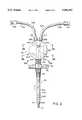
- FIG. 2is an enlarged schematic diagram of the hemodialysis catheter and catheter assembly of the invention in a flow-through position
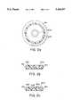
- FIGS. 2a, 2b and 2care views through indicated locations of the hemodialysis catheter and catheter assembly of FIG. 2.
- FIG. 3is an enlarged schematic diagram of the hemodialysis catheter and catheter assembly of the invention in the usual closed position.
- the catheter assembly 40includes catheter 50, catheter adapter 52, and flexible extenders 53a, 53b.
- the catheter 50is generally comprised of concentric lumens 50a and 50b, and preferably further includes a strain relief 54, a mesh sleeve 56, and a winged fixation device 58.
- the lumens 50a and 50b of catheter 50are preferably made from a thin biocompatible and biostable material such as, e.g., polyurethane, or polycarbonate urethane. A Shore 80A to 55D Durometer polyurethane is preferred.
- the lumens 50a and 50bare generally concentric, with inner lumen 50a being preferably utilized for outflow and outer lumen 50b being utilized for inflow. As seen in FIG. 2, the inner lumen 50a extends beyond the outer lumen 50b with the inner lumen 50a terminating inside a solid tip 57, and the outer lumen 50b terminating at the proximal end of the solid tip 57.
- the solid tip 57is preferably made from polyurethane, and may include a radiopaque formulation or filler such that the tip of the cannula can be observed under fluoroscopy. As described hereinafter, the proximal end of the tip 57 may also contain an anticoagulant drug reservoir.
- the distal end of the outer lumen 50b of the preferred embodimenthas radial holes 60b therethrough for receiving blood.
- radial holes 60btherethrough for receiving blood.
- two or three sets of four holes extending around the lumenare provided, with the total area of the holes being at least equal to the cross sectional area of annular lumen 50b.
- the provision of radial holes around the outer lumen 50bpermits blood to be pumped in from all sides, thus preventing the sucking in of the blood vessel wall.
- the inner lumen 50ais likewise provided with one or more sets of radial holes 60a which extend radially through the tip section 59. With the radial holes, when blood is flowing out of the holes, the catheter 50 is forced toward the center of the blood vessel in which it is located.
- a distal hole 61 at the distal end of the tip 59is also provided for the exit of the blood.
- the tip section of the catheteris preferably provided with holes which match holes 60a, and the tip can be insert molded, heat fused, or injection molded, and then heat fused or solvent bonded in place over the inner lumen 50a and to the distal end of the outer lumen 50b.
- the most distal portion of the outer lumen 50bmay not include holes, thereby forming a reservoir at the bottom of the outer lumen 50b; i.e., at the proximal end of the tip.
- the reservoirmay then be filled a slow release anticoagulant agent which will slowly release an anticoagulant when blood is stationary in the outer lumen 50b (i.e., when hemodialysis is not being performed).
- the slow release of anticoagulantwill prevent clots from forming and clogging the radial holes 60a, and could eliminate the need for a heparin flush procedure.
- the reservoirmay take different forms as desired.
- the reservoirmay be a simple polymer matrix such as silicone rubber which is compounded with an anticoagulant and then cured.
- the matrixmay take the form of a controlled release mechanism encapsulated in a semipermeable membrane.
- the inner lumen 50a and outer lumen 50bare sized so that the cross sectional flow area of the outer lumen 50b (i.e., the cross sectional area defined by the inner diameter of the outer lumen minus the cross sectional area defined by the outer diameter of the inner lumen) is larger than the cross sectional flow area of the inner lumen 50a (i.e., the cross sectional area defined by the inner diameter of the inner lumen). It has been found that with such an arrangement, a higher balanced blood flow rate is obtainable, as without such an arrangement, the surface areas presented by the outer surface of the inner lumen and the inner surface of the outer lumen, provide drag on the flow in the outer lumen and tend to cause a reduction in the flow through the outer lumen.
- the flow area in the outer lumenis in a range of approximately forty to fifty percent larger than the flow area of the inner lumen.
- the outer lumenhas a diameter which is more than ⁇ 2 times the diameter of the inner lumen.
- the inner lumen 50amay be made of a polyurethane having a Shore 90A to 55D Durometer, and provided with an inner diameter of 0.080-0.085 inches and an outer diameter of 0.092 to 0.096 inches.
- the outer lumen 50bmay be made of the same polyurethane material and provided with an inner diameter of 0.135 to 0.140 inches, and an outer diameter of 0.150 to 0.155 inches. With the provided diameters, when the inner lumen 50a is inserted in the outer lumen 50b, the outer lumen has a cross-sectional flow area which is approximately 40-50% larger than the cross-sectional flow area of the inner lumen. This additional flow area permits a flow rate of between 250 to 400 ml/min at 120 min Hg hydrostatic pressure, where lower flow rates would be obtained if the cross sectional flow areas of the inner lumen and outer lumen were to be the same.
- the proximal end of the preferred catheter 50 of the inventionextends at least partially into an adapter 52 which sealingly divides the lumens into a non-concentric branched arrangement.
- the adapter 52includes a channel 64 which has branches 64a, 64b, and 64c.
- branch 64creceives lumens 50a and 50b in their concentric arrangement, while branch 64a receives lumen 50a, and branch 64b receives lumen 50b.
- the outer lumen 50bis provided with a hole 66 through which the inner lumen 50a passes as it enters branch 64b.
- branch 64creceives lumens 50a and 50b in their concentric arrangement.
- outer lumen 50bbranches (in a Y) so that channel branch 64b receives one branch of the outer lumen 50b only, while channel branch 64a receives the inner lumen 50a with the other branch of the outer lumen 50b therearound.
- the outer diameter of inner lumen 50ais chosen to be substantially the same as the inner diameter of the branch of the outer lumen and the two are sealed together so that no fluid can flow therebetween.
- the adapterreceives the concentric lumens, and sealingly divides them out so that they assume a non-concentric branched arrangement.
- the lumens 50a and 50bpreferably extend through the adapter 52 and terminate at nipples 68a, 68b which extend from the adapter. It will be appreciated, however, that while not preferred, it is possible to terminate the lumens inside the adapter channels, with the adapter channels serving to actually carry blood.
- the nipples 68a and 68bare provided as a convenient mating mechanism for flexible extenders 53a, 53b.
- the flexible extendersare preferably made from silicone rubber, although other soft resilient materials such as polyurethanes, polyolefins, and the like may be used. As indicated by FIGS.
- the flexible extendersmust be soft enough to kink or bend sufficiently so as to stem all fluid flow through the extender (as indicated at 70a, 70b of FIG. 3), while being resilient enough to resume a position which permits fluid flow therethrough (as seen in FIG. 2).
- the flexible extendersinclude first ends 71a, 71b which mate with nipples 68a, 68b, and second ends 73a, 73b which terminate in fluid connectors such as a male or female luer slip or luer lock 75a, 75b. In this manner, the catheter assembly 40 is easily coupled to other fluid flow lines (not shown) which are typically used in conjunction with hemodialysis machines.
- the adapter 52is preferably provided with grooves 80a, 80b.
- grooves 80a, 80bhave smaller diameter sections 81a, 81b through which the flexible extenders may be forced, and larger diameter sections 82a, 82b which hold the connectors without significantly squeezing them. If properly dimensioned, the flexible extenders will not slip through the grooves in the adapter and open the closed kinks because connectors 75a, 75b at the end of the extenders are of a larger diameter than the larger diameter sections 82a, 82b of the grooves and will act as a stop.
- adapter 52is preferably formed as a flat disk of polished rigid plastic such as polycarbonate or polyurethane of Shore 55D to 75D Durometer with smooth outer surfaces. The arrangement is not unsightly, and because of its smooth surface is not uncomfortable for the patient.
- the catheter 50is preferably provided with a strain relief 54 which is adherently coupled to both the adapter 52 and the catheter 50.
- the .catheteris also preferably provided with a porous polyurethane mesh 56 along a portion of its outer surface which is intended to be in contact with the skin (fascia) of the patient.
- the polyurethane meshis preferably spun according to the method disclosed in U.S. Pat. No. 4,475,972 to Wong, and is both biocompatible and substantially biostable so that the catheter may remain in the patient without disintegrating and without causing infection.
- the mesh 56acts as a scaffold for tissue ingrowth, thereby eliminating the sinus tract which usually occurs when smooth tubes are placed percutaneously, and reducing risk of infection.
- the mesh 30can contain or be impregnated with bactericides, antibiotics, and other drugs such as protamine and like, or sputter coated with a bactericidal agent such as silver, silver-nitrate, or cyclohexadine to further reduce risk of infection.
- the catheter 50may be provided with a winged fixation device 58. While the winged fixation device 58 may not be necessary when the porous mesh 56 is provided, standard hemodialysis catheters are,provided with such devices.
- the winged fixation device 58is provided with holes 59 for suturing as is known in the art.
- the adaptercould be square, oblong, or otherwise shaped, and instead of having nipples, could be provided with male or female luer slips or locks or other mating mechanisms either external or internal the adapter. Therefore, it is apparent to those skilled in the art that additional changes and modifications may be made to the invention as described in the specification without departing from the spirit and scope of the invention.
Landscapes
- Health & Medical Sciences (AREA)
- Vascular Medicine (AREA)
- Engineering & Computer Science (AREA)
- Anesthesiology (AREA)
- Biomedical Technology (AREA)
- Heart & Thoracic Surgery (AREA)
- Hematology (AREA)
- Life Sciences & Earth Sciences (AREA)
- Animal Behavior & Ethology (AREA)
- General Health & Medical Sciences (AREA)
- Public Health (AREA)
- Veterinary Medicine (AREA)
- External Artificial Organs (AREA)
Abstract
Description
Claims (37)
Priority Applications (1)
| Application Number | Priority Date | Filing Date | Title |
|---|---|---|---|
| US08/087,173US5360397A (en) | 1993-07-02 | 1993-07-02 | Hemodiaylsis catheter and catheter assembly |
Applications Claiming Priority (1)
| Application Number | Priority Date | Filing Date | Title |
|---|---|---|---|
| US08/087,173US5360397A (en) | 1993-07-02 | 1993-07-02 | Hemodiaylsis catheter and catheter assembly |
Publications (1)
| Publication Number | Publication Date |
|---|---|
| US5360397Atrue US5360397A (en) | 1994-11-01 |
Family
ID=22203536
Family Applications (1)
| Application Number | Title | Priority Date | Filing Date |
|---|---|---|---|
| US08/087,173Expired - LifetimeUS5360397A (en) | 1993-07-02 | 1993-07-02 | Hemodiaylsis catheter and catheter assembly |
Country Status (1)
| Country | Link |
|---|---|
| US (1) | US5360397A (en) |
Cited By (127)
| Publication number | Priority date | Publication date | Assignee | Title |
|---|---|---|---|---|
| US5628788A (en)* | 1995-11-07 | 1997-05-13 | Corvita Corporation | Self-expanding endoluminal stent-graft |
| US5630804A (en)* | 1995-02-24 | 1997-05-20 | Baxter International Inc. | Metallic silver-plated silicon ring element for exit site disinfection and a method for preventing contamination at an exit site |
| US5700269A (en)* | 1995-06-06 | 1997-12-23 | Corvita Corporation | Endoluminal prosthesis deployment device for use with prostheses of variable length and having retraction ability |
| US5707351A (en)* | 1995-06-06 | 1998-01-13 | C.R. Bard, Inc. | Remote tubing assembly |
| US5741333A (en)* | 1995-04-12 | 1998-04-21 | Corvita Corporation | Self-expanding stent for a medical device to be introduced into a cavity of a body |
| WO1998024374A1 (en)* | 1996-12-05 | 1998-06-11 | Loma Linda University Medical Center | Vascular wound closure system |
| US5800407A (en)* | 1995-12-21 | 1998-09-01 | Eldor; Joseph | Multiple hole epidural catheter |
| US5814010A (en)* | 1995-08-08 | 1998-09-29 | Allergan, Inc. | Safety-vac capsule polisher |
| US5849037A (en)* | 1995-04-12 | 1998-12-15 | Corvita Corporation | Self-expanding stent for a medical device to be introduced into a cavity of a body, and method for its preparation |
| US5869127A (en)* | 1995-02-22 | 1999-02-09 | Boston Scientific Corporation | Method of providing a substrate with a bio-active/biocompatible coating |
| WO1999042164A1 (en)* | 1998-02-19 | 1999-08-26 | Percusurge, Inc. | Catheter shaft |
| US5961485A (en)* | 1993-03-16 | 1999-10-05 | Vas-Cath Incorporated | Coaxial dual lumen catheter |
| US5968091A (en)* | 1996-03-26 | 1999-10-19 | Corvita Corp. | Stents and stent grafts having enhanced hoop strength and methods of making the same |
| US5976103A (en)* | 1991-09-26 | 1999-11-02 | Vas-Cath Incorporated | Dual lumen coaxial catheter |
| US6004341A (en)* | 1996-12-05 | 1999-12-21 | Loma Linda University Medical Center | Vascular wound closure device |
| US6179817B1 (en) | 1995-02-22 | 2001-01-30 | Boston Scientific Corporation | Hybrid coating for medical devices |
| US6197051B1 (en) | 1997-06-18 | 2001-03-06 | Boston Scientific Corporation | Polycarbonate-polyurethane dispersions for thromobo-resistant coatings |
| US6261255B1 (en) | 1998-11-06 | 2001-07-17 | Ronald Jay Mullis | Apparatus for vascular access for chronic hemodialysis |
| US6280423B1 (en) | 1998-02-24 | 2001-08-28 | Scimed Life Systems, Inc. | High flow rate dialysis catheters and related methods |
| US6287322B1 (en)* | 1995-12-07 | 2001-09-11 | Loma Linda University Medical Center | Tissue opening locator and everter and method |
| US6293927B1 (en) | 1997-07-24 | 2001-09-25 | Rex Medical | Stationary central tunnel dialysis catheter with optional separable sheath |
| US6332892B1 (en) | 1999-03-02 | 2001-12-25 | Scimed Life Systems, Inc. | Medical device with one or more helical coils |
| US6338724B1 (en) | 1999-03-29 | 2002-01-15 | Christos D. Dossa | Arterio-venous interconnection |
| US6355034B2 (en) | 1996-09-20 | 2002-03-12 | Ioan Cosmescu | Multifunctional telescopic monopolar/bipolar surgical device and method therefor |
| US6524326B1 (en) | 1995-12-07 | 2003-02-25 | Loma Linda University Medical Center | Tissue opening locator and everter and method |
| US20030149472A1 (en)* | 1995-11-07 | 2003-08-07 | Leonard Pinchuk | Modular endluminal stent-grafts and methods for their use |
| US6620202B2 (en) | 2001-10-16 | 2003-09-16 | Scimed Life Systems, Inc. | Medical stent with variable coil and related methods |
| US20030191425A1 (en)* | 2002-04-04 | 2003-10-09 | Melvin Rosenblatt | Blood treatment catheter and method |
| US6638242B2 (en)* | 2001-01-24 | 2003-10-28 | Jon S. Wilson | Multi-lumen catheter with attachable hub |
| US6656146B1 (en) | 1995-11-07 | 2003-12-02 | Scimed Life Systems, Inc. | Medical device with tail(s) |
| US20030229321A1 (en)* | 2002-06-05 | 2003-12-11 | Timothy Simon | Needle with slotted tip |
| US20040010216A1 (en)* | 2000-02-24 | 2004-01-15 | Zhu Yong Hua | Device for closing tissue openings |
| US6682508B1 (en)* | 1999-03-03 | 2004-01-27 | Uab Research Foundation | Direct central nervous system catheter and temperature control system |
| US20040024358A1 (en)* | 1999-03-03 | 2004-02-05 | The Uab Research Foundation | Direct central nervous system catheter and temperature control system |
| US20040054406A1 (en)* | 2000-12-19 | 2004-03-18 | Alexander Dubson | Vascular prosthesis and method for production thereof |
| US6709706B2 (en) | 1995-02-22 | 2004-03-23 | Scimed Life Systems, Inc. | Hydrophilic coating and substrates coated therewith having enhanced durablity and lubricity |
| US6719804B2 (en) | 2001-04-02 | 2004-04-13 | Scimed Life Systems, Inc. | Medical stent and related methods |
| US6723121B1 (en) | 1997-06-18 | 2004-04-20 | Scimed Life Systems, Inc. | Polycarbonate-polyurethane dispersions for thrombo-resistant coatings |
| US20040171997A1 (en)* | 2001-01-24 | 2004-09-02 | Wilson Jon S. | Double-y-shaped multi-lumen catheter with selectively attachable hubs |
| US20040210208A1 (en)* | 2003-04-16 | 2004-10-21 | Cook Incorporated | Medical device with therapeutic agents |
| US6814718B2 (en) | 2001-01-09 | 2004-11-09 | Rex Medical, L.P | Dialysis catheter |
| US20050095275A1 (en)* | 2003-09-05 | 2005-05-05 | Zhu Yong H. | Dressing delivery system for internal wounds |
| US6890342B2 (en) | 2000-08-02 | 2005-05-10 | Loma Linda University | Method and apparatus for closing vascular puncture using hemostatic material |
| US20050131454A1 (en)* | 1998-03-10 | 2005-06-16 | Grant Hieshima | Embolic coil hydraulic deployment system |
| WO2005058404A1 (en)* | 2003-12-17 | 2005-06-30 | Skansen Jan | Catheter device |
| US6921396B1 (en) | 2002-08-30 | 2005-07-26 | Arrow International, Inc. | Multi-lumen catheter with integrated connector |
| US20050209583A1 (en)* | 2004-03-18 | 2005-09-22 | Powers Kelly B | Connector system for a proximally trimmable catheter |
| US20050209581A1 (en)* | 2004-03-18 | 2005-09-22 | Butts M D | Catheter connector |
| US20050245900A1 (en)* | 2003-09-08 | 2005-11-03 | Ash Access Technology, Inc. | Anti-clotting indwelling catheter |
| EP1600186A1 (en)* | 1999-03-03 | 2005-11-30 | UAB Research Foundation | Direct central nervous system catheter and temperature control system |
| US20050283124A1 (en)* | 2002-06-05 | 2005-12-22 | Timothy Simon | Needle with slotted tip |
| US6986752B2 (en) | 2001-01-09 | 2006-01-17 | Rex Medical, Lp | Peritoneal dialysis catheter and insertion method |
| US6991614B2 (en) | 1995-11-07 | 2006-01-31 | Boston Scientific Scimed, Inc. | Ureteral stent for improved patient comfort |
| US7011645B2 (en) | 2001-01-09 | 2006-03-14 | Rex Medical, L.P. | Dialysis catheter |
| US7077829B2 (en) | 2001-01-09 | 2006-07-18 | Rex Medical, L.P. | Dialysis catheter |
| US20060161100A1 (en)* | 2005-01-20 | 2006-07-20 | Ameco Medical Industries | MultiTube Catheter And Method For Making The Same |
| US7097635B2 (en) | 2001-01-09 | 2006-08-29 | Rex Medical, L.P. | Guidewire retrieval member for catheter insertion |
| US7128734B1 (en) | 2002-09-20 | 2006-10-31 | Arrow International, Inc. | Apparatus and method for reverse tunneling a multi-lumen catheter in a patient |
| US20070073239A1 (en)* | 2003-12-17 | 2007-03-29 | Jan Skansen | Catheter device |
| US20070100298A1 (en)* | 2002-04-04 | 2007-05-03 | Angiodynamics, Inc. | Catheter fluid lock method and device |
| US20070110935A1 (en)* | 2004-06-07 | 2007-05-17 | Boston Scientific Scimed, Inc. | Silk reinforcement of expandable medical balloons |
| US20070149949A1 (en)* | 2003-04-12 | 2007-06-28 | Medical Research Products-B, Inc. | Apparatus and method for percutaneous catheter implantation and replacement |
| US20070149951A1 (en)* | 2005-12-27 | 2007-06-28 | Mina Wu | Variable stiffness guidewire |
| US7244272B2 (en) | 2000-12-19 | 2007-07-17 | Nicast Ltd. | Vascular prosthesis and method for production thereof |
| US20070225661A1 (en)* | 2006-03-24 | 2007-09-27 | Ash Access Technology, Inc. | Indwelling catheter with anti-clotting features |
| US20070225678A1 (en)* | 2006-03-23 | 2007-09-27 | Cook Vascular Incorporated | Two-way valved catheter |
| US20070225682A1 (en)* | 2006-03-24 | 2007-09-27 | Ash Stephen R | Anti-clotting indwelling catheter |
| US7300430B2 (en)* | 2001-01-24 | 2007-11-27 | Arrow International, Inc. | Multi-lumen catheter with attachable hub |
| US20070276470A1 (en)* | 2006-05-26 | 2007-11-29 | Dirk Tenne | Occlusion device combination of stent and mesh having offset parallelogram porosity |
| US20070276469A1 (en)* | 2006-05-26 | 2007-11-29 | Dirk Tenne | Occlusion device combination of stent and mesh with diamond-shaped porosity |
| US20070288049A1 (en)* | 2006-06-12 | 2007-12-13 | Richard Champion Davis | Modified headpiece for hydraulic coil deployment system |
| US20070293928A1 (en)* | 2006-06-14 | 2007-12-20 | Damian Tomlin | Retrieval device with sidewall grippers |
| US20080009832A1 (en)* | 2005-06-20 | 2008-01-10 | C. R. Bard, Inc. | Connection system for multi-lumen catheter |
| WO2008005065A1 (en)* | 2006-07-05 | 2008-01-10 | Medical Research Products-B, Inc. | Apparatus and method for percutaneous catheter implantation and replacement |
| US20080081062A1 (en)* | 2006-10-03 | 2008-04-03 | Nippon Sherwood Medical Industries Ltd. | Medical apparatus and method for producing same |
| US20080103480A1 (en)* | 2006-10-26 | 2008-05-01 | Cook Critical Care Incorporated | Catheter port configuration |
| US7393339B2 (en) | 2003-02-21 | 2008-07-01 | C. R. Bard, Inc. | Multi-lumen catheter with separate distal tips |
| US20090018493A1 (en)* | 2007-07-10 | 2009-01-15 | Ash Stephen R | Implantable catheter assembly |
| US20090054825A1 (en)* | 2007-08-21 | 2009-02-26 | Cook Critical Care Incorporated | Winged catheter assembly |
| US20090054824A1 (en)* | 2007-08-21 | 2009-02-26 | Cook Critical Care Incorporated | Multi-lumen catheter assembly |
| US20090054826A1 (en)* | 2007-08-21 | 2009-02-26 | Cook Critical Care Incorporated | Multi-lumen catheter |
| US20090118661A1 (en)* | 2007-11-01 | 2009-05-07 | C. R. Bard, Inc. | Catheter assembly including triple lumen tip |
| US20090171295A1 (en)* | 2006-07-05 | 2009-07-02 | Porter Christopher H | Enhanced apparatus for percutaneous catheter implantation and replacement |
| US7766935B2 (en) | 2006-06-12 | 2010-08-03 | Codman & Shurtleff, Inc. | Modified headpiece for hydraulic coil deployment system |
| US7785317B2 (en) | 2006-03-29 | 2010-08-31 | Codman & Shurtleff, Inc. | Joined metal tubing and method of manufacture |
| US7794219B2 (en) | 2001-03-20 | 2010-09-14 | Nicast Ltd. | Portable electrospinning device |
| US7854731B2 (en) | 2004-03-18 | 2010-12-21 | C. R. Bard, Inc. | Valved catheter |
| US20110015564A1 (en)* | 2008-03-20 | 2011-01-20 | Bonnette Michael J | Direct Stream Hydrodynamic Catheter System |
| US20110066141A1 (en)* | 2009-09-11 | 2011-03-17 | Cook Incorporated | Implantable medical device having an anti-gastric distress agent |
| US20110137225A1 (en)* | 2009-12-04 | 2011-06-09 | Cook Critical Care Incorporated | Multi-lumen catheter |
| US8012167B2 (en) | 2003-08-14 | 2011-09-06 | Loma Linda University Medical Center | Vascular wound closure device and method |
| US8021321B2 (en) | 2002-02-07 | 2011-09-20 | C. R. Bard, Inc. | Split tip dialysis catheter |
| US8066660B2 (en) | 2007-10-26 | 2011-11-29 | C. R. Bard, Inc. | Split-tip catheter including lateral distal openings |
| US8083728B2 (en) | 2004-03-18 | 2011-12-27 | C. R. Bard, Inc. | Multifunction adaptor for an open-ended catheter |
| US8177770B2 (en) | 2004-04-01 | 2012-05-15 | C. R. Bard, Inc. | Catheter connector system |
| US8206371B2 (en) | 2003-05-27 | 2012-06-26 | Bard Access Systems, Inc. | Methods and apparatus for inserting multi-lumen split-tip catheters into a blood vessel |
| US20120203199A1 (en)* | 2010-11-30 | 2012-08-09 | Incumed, Llc | Method and apparatus for providing access to an internal body organ |
| US8292841B2 (en) | 2007-10-26 | 2012-10-23 | C. R. Bard, Inc. | Solid-body catheter including lateral distal openings |
| US8323228B2 (en) | 2007-04-12 | 2012-12-04 | Rex Medical L.P. | Dialysis catheter |
| US8337484B2 (en) | 2009-06-26 | 2012-12-25 | C. R. Band, Inc. | Proximally trimmable catheter including pre-attached bifurcation and related methods |
| US8454565B2 (en) | 2006-09-28 | 2013-06-04 | Covidien Lp | Low profile catheter assembly |
| US8491628B2 (en) | 2000-08-01 | 2013-07-23 | Loma Linda University Medical Center | Vascular wound closure device and method |
| US8500939B2 (en) | 2007-10-17 | 2013-08-06 | Bard Access Systems, Inc. | Manufacture of split tip catheters |
| US8500675B2 (en) | 2005-01-20 | 2013-08-06 | M. Samy Ahmed Hamboly | Multilumen catheter with pressure resistant lumen and method |
| US20130231605A1 (en)* | 2012-03-05 | 2013-09-05 | Wake Forest University Health Sciences | Multi-purpose aspiration/irrigation/polishing tips suitable for cataract surgeries and related methods |
| US8591450B2 (en) | 2010-06-07 | 2013-11-26 | Rex Medical L.P. | Dialysis catheter |
| US8597258B2 (en) | 2009-08-31 | 2013-12-03 | Covidien Lp | Valved catheter |
| US8747343B2 (en) | 2011-09-30 | 2014-06-10 | Covidien Lp | Hemodialysis catheter with improved side opening design |
| US8864724B2 (en) | 2008-05-14 | 2014-10-21 | Covidien Lp | Catheter with valve |
| US20150005753A1 (en)* | 2012-03-05 | 2015-01-01 | Wake Forest University Health Sciences | Medical tools with aspiration tips suitable for cataract surgeries and related methods |
| US8986263B2 (en) | 2011-03-08 | 2015-03-24 | Covidien Lp | Catheter with valve |
| US8992454B2 (en) | 2004-06-09 | 2015-03-31 | Bard Access Systems, Inc. | Splitable tip catheter with bioresorbable adhesive |
| US9005154B2 (en) | 2008-09-26 | 2015-04-14 | Covidien Lp | Valved hemodialysis catheter |
| US9072867B2 (en) | 2011-09-30 | 2015-07-07 | Covidien Lp | Catheter with external flow channel |
| US9155862B2 (en) | 2012-09-28 | 2015-10-13 | Covidien Lp | Symmetrical tip acute catheter |
| US9168355B2 (en) | 2006-09-29 | 2015-10-27 | Covidien Lp | Acute hemodialysis catheter assembly |
| EP2962720A1 (en)* | 2014-07-04 | 2016-01-06 | Abiomed Europe GmbH | Sheath for sealed access to a vessel |
| USD748252S1 (en) | 2013-02-08 | 2016-01-26 | C. R. Bard, Inc. | Multi-lumen catheter tip |
| US9579485B2 (en) | 2007-11-01 | 2017-02-28 | C. R. Bard, Inc. | Catheter assembly including a multi-lumen configuration |
| US9586023B2 (en) | 1998-02-06 | 2017-03-07 | Boston Scientific Limited | Direct stream hydrodynamic catheter system |
| US9656043B2 (en) | 2011-03-08 | 2017-05-23 | Cook Medical Technologies Llc | Multi-split-tipped catheter |
| US10058676B2 (en) | 2009-09-30 | 2018-08-28 | Covidien Lp | Medical catheter having a design providing low recirculation and reversibility |
| US10143822B2 (en) | 2012-07-05 | 2018-12-04 | Covidien Lp | Valved tip catheters |
| US10258768B2 (en) | 2014-07-14 | 2019-04-16 | C. R. Bard, Inc. | Apparatuses, systems, and methods for inserting catheters having enhanced stiffening and guiding features |
| US11471647B2 (en) | 2014-11-07 | 2022-10-18 | C. R. Bard, Inc. | Connection system for tunneled catheters |
| US11730939B2 (en) | 2014-07-04 | 2023-08-22 | Abiomed Europe Gmbh | Sheath for sealed access to a vessel |
| US11896782B2 (en) | 2017-08-23 | 2024-02-13 | C. R. Bard, Inc. | Priming and tunneling system for a retrograde catheter assembly |
Citations (9)
| Publication number | Priority date | Publication date | Assignee | Title |
|---|---|---|---|---|
| US3929126A (en)* | 1974-09-26 | 1975-12-30 | Jay C Corsaut | Surgical suction irrigator |
| US4134402A (en)* | 1976-02-11 | 1979-01-16 | Mahurkar Sakharam D | Double lumen hemodialysis catheter |
| US4323071A (en)* | 1978-04-24 | 1982-04-06 | Advanced Catheter Systems, Inc. | Vascular guiding catheter assembly and vascular dilating catheter assembly and a combination thereof and methods of making the same |
| US4583968A (en)* | 1983-10-03 | 1986-04-22 | Mahurkar Sakharam D | Smooth bore double lumen catheter |
| US4692141A (en)* | 1982-03-08 | 1987-09-08 | Mahurkar Sakharam D | Double lumen catheter |
| US4871357A (en)* | 1986-01-21 | 1989-10-03 | Baxter International Inc. | Ionic heparin coating |
| US4895561A (en)* | 1988-05-16 | 1990-01-23 | Mahurkar Sakharam D | Dual-lumen catheter-connecting system |
| US4935006A (en)* | 1987-11-12 | 1990-06-19 | Hasson Harrith M | Suction and irrigation device with right angle and oblique openings |
| US5188593A (en)* | 1988-04-21 | 1993-02-23 | Vas-Cath Incorporated | Dual lumen catheter |
- 1993
- 1993-07-02USUS08/087,173patent/US5360397A/ennot_activeExpired - Lifetime
Patent Citations (11)
| Publication number | Priority date | Publication date | Assignee | Title |
|---|---|---|---|---|
| US3929126A (en)* | 1974-09-26 | 1975-12-30 | Jay C Corsaut | Surgical suction irrigator |
| US4134402A (en)* | 1976-02-11 | 1979-01-16 | Mahurkar Sakharam D | Double lumen hemodialysis catheter |
| US4134402B1 (en)* | 1976-02-11 | 1989-07-25 | ||
| US4323071A (en)* | 1978-04-24 | 1982-04-06 | Advanced Catheter Systems, Inc. | Vascular guiding catheter assembly and vascular dilating catheter assembly and a combination thereof and methods of making the same |
| US4323071B1 (en)* | 1978-04-24 | 1990-05-29 | Advanced Cardiovascular System | |
| US4692141A (en)* | 1982-03-08 | 1987-09-08 | Mahurkar Sakharam D | Double lumen catheter |
| US4583968A (en)* | 1983-10-03 | 1986-04-22 | Mahurkar Sakharam D | Smooth bore double lumen catheter |
| US4871357A (en)* | 1986-01-21 | 1989-10-03 | Baxter International Inc. | Ionic heparin coating |
| US4935006A (en)* | 1987-11-12 | 1990-06-19 | Hasson Harrith M | Suction and irrigation device with right angle and oblique openings |
| US5188593A (en)* | 1988-04-21 | 1993-02-23 | Vas-Cath Incorporated | Dual lumen catheter |
| US4895561A (en)* | 1988-05-16 | 1990-01-23 | Mahurkar Sakharam D | Dual-lumen catheter-connecting system |
Cited By (250)
| Publication number | Priority date | Publication date | Assignee | Title |
|---|---|---|---|---|
| US5976103A (en)* | 1991-09-26 | 1999-11-02 | Vas-Cath Incorporated | Dual lumen coaxial catheter |
| US5961485A (en)* | 1993-03-16 | 1999-10-05 | Vas-Cath Incorporated | Coaxial dual lumen catheter |
| US5869127A (en)* | 1995-02-22 | 1999-02-09 | Boston Scientific Corporation | Method of providing a substrate with a bio-active/biocompatible coating |
| US6099563A (en)* | 1995-02-22 | 2000-08-08 | Boston Scientific Corporation | Substrates, particularly medical devices, provided with bio-active/biocompatible coatings |
| US6179817B1 (en) | 1995-02-22 | 2001-01-30 | Boston Scientific Corporation | Hybrid coating for medical devices |
| US6709706B2 (en) | 1995-02-22 | 2004-03-23 | Scimed Life Systems, Inc. | Hydrophilic coating and substrates coated therewith having enhanced durablity and lubricity |
| US5630804A (en)* | 1995-02-24 | 1997-05-20 | Baxter International Inc. | Metallic silver-plated silicon ring element for exit site disinfection and a method for preventing contamination at an exit site |
| US6237460B1 (en) | 1995-04-12 | 2001-05-29 | Corvita Corporation | Method for preparation of a self-expanding stent for a medical device to be introduced into a cavity of a body |
| US5849037A (en)* | 1995-04-12 | 1998-12-15 | Corvita Corporation | Self-expanding stent for a medical device to be introduced into a cavity of a body, and method for its preparation |
| US5741333A (en)* | 1995-04-12 | 1998-04-21 | Corvita Corporation | Self-expanding stent for a medical device to be introduced into a cavity of a body |
| US5707351A (en)* | 1995-06-06 | 1998-01-13 | C.R. Bard, Inc. | Remote tubing assembly |
| US5700269A (en)* | 1995-06-06 | 1997-12-23 | Corvita Corporation | Endoluminal prosthesis deployment device for use with prostheses of variable length and having retraction ability |
| US5814010A (en)* | 1995-08-08 | 1998-09-29 | Allergan, Inc. | Safety-vac capsule polisher |
| US6991614B2 (en) | 1995-11-07 | 2006-01-31 | Boston Scientific Scimed, Inc. | Ureteral stent for improved patient comfort |
| US7678154B2 (en) | 1995-11-07 | 2010-03-16 | Boston Scientific Scimed, Inc. | Ureteral stent for improved patient comfort |
| US6849069B1 (en) | 1995-11-07 | 2005-02-01 | Boston Scientitfic Corporation | Medical device with tail(s) for assisting flow of urine |
| US6945950B2 (en) | 1995-11-07 | 2005-09-20 | Boston Scientific Scimed, Inc. | Ureteral stent with small bladder tail(s) |
| US8845752B2 (en) | 1995-11-07 | 2014-09-30 | Boston Scientific Scimed, Inc. | Ureteral stent for improved patient comfort |
| US6656146B1 (en) | 1995-11-07 | 2003-12-02 | Scimed Life Systems, Inc. | Medical device with tail(s) |
| US5628788A (en)* | 1995-11-07 | 1997-05-13 | Corvita Corporation | Self-expanding endoluminal stent-graft |
| US20030149472A1 (en)* | 1995-11-07 | 2003-08-07 | Leonard Pinchuk | Modular endluminal stent-grafts and methods for their use |
| US6425901B1 (en) | 1995-12-07 | 2002-07-30 | Loma Linda University Medical Center | Vascular wound closure system |
| US6524326B1 (en) | 1995-12-07 | 2003-02-25 | Loma Linda University Medical Center | Tissue opening locator and everter and method |
| US6287322B1 (en)* | 1995-12-07 | 2001-09-11 | Loma Linda University Medical Center | Tissue opening locator and everter and method |
| US6964675B2 (en) | 1995-12-07 | 2005-11-15 | Loma Linda University Medical Center | Tissue opening locator and everter and method |
| US5800407A (en)* | 1995-12-21 | 1998-09-01 | Eldor; Joseph | Multiple hole epidural catheter |
| US5968091A (en)* | 1996-03-26 | 1999-10-19 | Corvita Corp. | Stents and stent grafts having enhanced hoop strength and methods of making the same |
| US6355034B2 (en) | 1996-09-20 | 2002-03-12 | Ioan Cosmescu | Multifunctional telescopic monopolar/bipolar surgical device and method therefor |
| US6702812B2 (en) | 1996-09-20 | 2004-03-09 | Ioan Cosmescu | Multifunctional telescopic monopolar/bipolar surgical device and method therefor |
| US6004341A (en)* | 1996-12-05 | 1999-12-21 | Loma Linda University Medical Center | Vascular wound closure device |
| WO1998024374A1 (en)* | 1996-12-05 | 1998-06-11 | Loma Linda University Medical Center | Vascular wound closure system |
| US6197051B1 (en) | 1997-06-18 | 2001-03-06 | Boston Scientific Corporation | Polycarbonate-polyurethane dispersions for thromobo-resistant coatings |
| US6723121B1 (en) | 1997-06-18 | 2004-04-20 | Scimed Life Systems, Inc. | Polycarbonate-polyurethane dispersions for thrombo-resistant coatings |
| US20040171747A1 (en)* | 1997-06-18 | 2004-09-02 | Sheng-Ping Zhong | Polycarbonate-polyurethane dispersions for thrombo-resistant coatings |
| US6293927B1 (en) | 1997-07-24 | 2001-09-25 | Rex Medical | Stationary central tunnel dialysis catheter with optional separable sheath |
| US9586023B2 (en) | 1998-02-06 | 2017-03-07 | Boston Scientific Limited | Direct stream hydrodynamic catheter system |
| US10321932B2 (en) | 1998-02-06 | 2019-06-18 | Boston Scientific Limited | Direct stream hydrodynamic catheter system |
| US6228072B1 (en) | 1998-02-19 | 2001-05-08 | Percusurge, Inc. | Shaft for medical catheters |
| WO1999042164A1 (en)* | 1998-02-19 | 1999-08-26 | Percusurge, Inc. | Catheter shaft |
| US6273878B1 (en) | 1998-02-19 | 2001-08-14 | Percusurge, Inc | Shaft for medical catheters |
| US6595966B2 (en) | 1998-02-24 | 2003-07-22 | Scimed Life Systems, Inc. | High flow rate dialysis catheters and related methods |
| US6280423B1 (en) | 1998-02-24 | 2001-08-28 | Scimed Life Systems, Inc. | High flow rate dialysis catheters and related methods |
| US7410602B2 (en) | 1998-02-24 | 2008-08-12 | Namic/Va, Inc. | High flow rate dialysis catheters and related methods |
| US20050131454A1 (en)* | 1998-03-10 | 2005-06-16 | Grant Hieshima | Embolic coil hydraulic deployment system |
| US6261255B1 (en) | 1998-11-06 | 2001-07-17 | Ronald Jay Mullis | Apparatus for vascular access for chronic hemodialysis |
| US6332892B1 (en) | 1999-03-02 | 2001-12-25 | Scimed Life Systems, Inc. | Medical device with one or more helical coils |
| US20040024358A1 (en)* | 1999-03-03 | 2004-02-05 | The Uab Research Foundation | Direct central nervous system catheter and temperature control system |
| US7014624B2 (en) | 1999-03-03 | 2006-03-21 | The Uab Research Foundation | Direct central nervous system catheter and temperature control system |
| US6682508B1 (en)* | 1999-03-03 | 2004-01-27 | Uab Research Foundation | Direct central nervous system catheter and temperature control system |
| EP1600186A1 (en)* | 1999-03-03 | 2005-11-30 | UAB Research Foundation | Direct central nervous system catheter and temperature control system |
| US6338724B1 (en) | 1999-03-29 | 2002-01-15 | Christos D. Dossa | Arterio-venous interconnection |
| US7931628B2 (en) | 2000-02-24 | 2011-04-26 | Loma Linda University Medical Center | Device for closing tissue openings |
| US20040010216A1 (en)* | 2000-02-24 | 2004-01-15 | Zhu Yong Hua | Device for closing tissue openings |
| US8491628B2 (en) | 2000-08-01 | 2013-07-23 | Loma Linda University Medical Center | Vascular wound closure device and method |
| US8425552B2 (en) | 2000-08-02 | 2013-04-23 | Loma Linda University Medical Center | Apparatus for closing vascular puncture |
| US9320505B2 (en) | 2000-08-02 | 2016-04-26 | Loma Linda University | Apparatus for closing vascular puncture |
| US8702750B2 (en) | 2000-08-02 | 2014-04-22 | Loma Linda University | Apparatus for closing vascular puncture |
| US6890342B2 (en) | 2000-08-02 | 2005-05-10 | Loma Linda University | Method and apparatus for closing vascular puncture using hemostatic material |
| US9101731B2 (en) | 2000-08-02 | 2015-08-11 | Loma Linda University Medical Center | Vascular wound closure device and method |
| US7244116B2 (en) | 2000-12-19 | 2007-07-17 | Nicast Ltd. | Apparatus for improving mechanical characteristics of nonwoven materials |
| US20040054406A1 (en)* | 2000-12-19 | 2004-03-18 | Alexander Dubson | Vascular prosthesis and method for production thereof |
| US7115220B2 (en) | 2000-12-19 | 2006-10-03 | Nicast Ltd. | Vascular prosthesis and method for production thereof |
| US7244272B2 (en) | 2000-12-19 | 2007-07-17 | Nicast Ltd. | Vascular prosthesis and method for production thereof |
| US7276271B2 (en) | 2000-12-19 | 2007-10-02 | Nicast Ltd. | Polymer fiber tubular structure having kinking resistance |
| US7112293B2 (en) | 2000-12-19 | 2006-09-26 | Nicast Ltd. | Method and apparatus for manufacturing polymer fiber shells via electrospinning |
| US20040096532A1 (en)* | 2000-12-19 | 2004-05-20 | Alexander Dubson | Polymer fiber tubular structure having kinking resistance |
| US20040096533A1 (en)* | 2000-12-19 | 2004-05-20 | Alexander Dubson | Method and apparatus of improving mechanical characteristics of nonwoven materials |
| US7077829B2 (en) | 2001-01-09 | 2006-07-18 | Rex Medical, L.P. | Dialysis catheter |
| US7204831B2 (en) | 2001-01-09 | 2007-04-17 | Rex Medical, L.P. | Guidewire retrieval member for catheter insertion |
| US6986752B2 (en) | 2001-01-09 | 2006-01-17 | Rex Medical, Lp | Peritoneal dialysis catheter and insertion method |
| US7390322B2 (en) | 2001-01-09 | 2008-06-24 | Rex Medical, L.P. | Dialysis catheter and methods of insertion |
| US7011645B2 (en) | 2001-01-09 | 2006-03-14 | Rex Medical, L.P. | Dialysis catheter |
| US7566316B2 (en) | 2001-01-09 | 2009-07-28 | Rex Medical, L.P | Dialysis catheter |
| US7799014B2 (en) | 2001-01-09 | 2010-09-21 | Rex Medical, L.P. | Dialysis catheter |
| US7074213B2 (en) | 2001-01-09 | 2006-07-11 | Rex Medical, L.P. | Dialysis catheter |
| US6814718B2 (en) | 2001-01-09 | 2004-11-09 | Rex Medical, L.P | Dialysis catheter |
| US6858019B2 (en) | 2001-01-09 | 2005-02-22 | Rex Medical, L.P. | Dialysis catheter and methods of insertion |
| US7097635B2 (en) | 2001-01-09 | 2006-08-29 | Rex Medical, L.P. | Guidewire retrieval member for catheter insertion |
| US9084850B2 (en) | 2001-01-09 | 2015-07-21 | Rex Medical L.P. | Dialysis catheter |
| US8500674B2 (en) | 2001-01-09 | 2013-08-06 | Rex Medical, L.P. | Dialysis catheter |
| US20040172003A1 (en)* | 2001-01-24 | 2004-09-02 | Wilson Jon S. | Method of inserting double-Y-shaped catheter with attachable hubs |
| US7381204B2 (en) | 2001-01-24 | 2008-06-03 | Arrow International, Inc. | Multi-lumen catheter with attachable hub |
| US6638242B2 (en)* | 2001-01-24 | 2003-10-28 | Jon S. Wilson | Multi-lumen catheter with attachable hub |
| US20040171997A1 (en)* | 2001-01-24 | 2004-09-02 | Wilson Jon S. | Double-y-shaped multi-lumen catheter with selectively attachable hubs |
| US6872198B1 (en)* | 2001-01-24 | 2005-03-29 | Arrow International, Inc. | Double-y-shaped multi-lumen catheter with selectively attachable hubs |
| US7749185B2 (en) | 2001-01-24 | 2010-07-06 | Wilson Jon S | Method of inserting double-Y-shaped catheter with attachable hubs |
| US20040065333A1 (en)* | 2001-01-24 | 2004-04-08 | Wilson Jon S. | Multi-lumen catheter with attachable hub |
| US7300430B2 (en)* | 2001-01-24 | 2007-11-27 | Arrow International, Inc. | Multi-lumen catheter with attachable hub |
| US7794219B2 (en) | 2001-03-20 | 2010-09-14 | Nicast Ltd. | Portable electrospinning device |
| US7291180B2 (en) | 2001-04-02 | 2007-11-06 | Boston Scientific Scimed, Inc. | Medical stent and related methods |
| US7951206B2 (en) | 2001-04-02 | 2011-05-31 | Boston Scientific Scimed, Inc. | Medical stent |
| US6719804B2 (en) | 2001-04-02 | 2004-04-13 | Scimed Life Systems, Inc. | Medical stent and related methods |
| US6620202B2 (en) | 2001-10-16 | 2003-09-16 | Scimed Life Systems, Inc. | Medical stent with variable coil and related methods |
| US7037345B2 (en) | 2001-10-16 | 2006-05-02 | Boston Scientific Scimed, Inc. | Medical stent with variable coil and related methods |
| US8021321B2 (en) | 2002-02-07 | 2011-09-20 | C. R. Bard, Inc. | Split tip dialysis catheter |
| US7833215B2 (en) | 2002-04-04 | 2010-11-16 | Angiodynamics, Inc. | Catheter fluid lock method and device |
| US6942635B2 (en)* | 2002-04-04 | 2005-09-13 | Angiodynamics, Inc. | Blood treatment catheter and method |
| US20070100298A1 (en)* | 2002-04-04 | 2007-05-03 | Angiodynamics, Inc. | Catheter fluid lock method and device |
| US20030191425A1 (en)* | 2002-04-04 | 2003-10-09 | Melvin Rosenblatt | Blood treatment catheter and method |
| US20050283124A1 (en)* | 2002-06-05 | 2005-12-22 | Timothy Simon | Needle with slotted tip |
| US20030229321A1 (en)* | 2002-06-05 | 2003-12-11 | Timothy Simon | Needle with slotted tip |
| US6921396B1 (en) | 2002-08-30 | 2005-07-26 | Arrow International, Inc. | Multi-lumen catheter with integrated connector |
| US7128734B1 (en) | 2002-09-20 | 2006-10-31 | Arrow International, Inc. | Apparatus and method for reverse tunneling a multi-lumen catheter in a patient |
| US8808227B2 (en) | 2003-02-21 | 2014-08-19 | C. R. Bard, Inc. | Multi-lumen catheter with separate distal tips |
| US7393339B2 (en) | 2003-02-21 | 2008-07-01 | C. R. Bard, Inc. | Multi-lumen catheter with separate distal tips |
| US8152951B2 (en) | 2003-02-21 | 2012-04-10 | C. R. Bard, Inc. | Multi-lumen catheter with separate distal tips |
| US9387304B2 (en) | 2003-02-21 | 2016-07-12 | C.R. Bard, Inc. | Multi-lumen catheter with separate distal tips |
| US7731697B2 (en) | 2003-04-12 | 2010-06-08 | Incumed Llc, A Nevada Limited Liability Co. | Apparatus and method for percutaneous catheter implantation and replacement |
| US20070149949A1 (en)* | 2003-04-12 | 2007-06-28 | Medical Research Products-B, Inc. | Apparatus and method for percutaneous catheter implantation and replacement |
| US7306580B2 (en) | 2003-04-16 | 2007-12-11 | Cook Incorporated | Medical device with therapeutic agents |
| US7780647B2 (en) | 2003-04-16 | 2010-08-24 | Cook Incorporated | Medical device with therapeutic agents |
| US20080051737A1 (en)* | 2003-04-16 | 2008-02-28 | Cook Incorporated | Medical device with therapeutic agents |
| US20040210208A1 (en)* | 2003-04-16 | 2004-10-21 | Cook Incorporated | Medical device with therapeutic agents |
| US9572956B2 (en) | 2003-05-27 | 2017-02-21 | Bard Access Systems, Inc. | Methods and apparatus for inserting multi-lumen split-tip catheters into a blood vessel |
| US8206371B2 (en) | 2003-05-27 | 2012-06-26 | Bard Access Systems, Inc. | Methods and apparatus for inserting multi-lumen split-tip catheters into a blood vessel |
| US8597275B2 (en) | 2003-05-27 | 2013-12-03 | Bard Access Systems, Inc. | Methods and apparatus for inserting multi-lumen split-tip catheters into a blood vessel |
| US10105514B2 (en) | 2003-05-27 | 2018-10-23 | Bard Access Systems, Inc. | Methods and apparatus for inserting multi-lumen split-tip catheters into a blood vessel |
| US10806895B2 (en) | 2003-05-27 | 2020-10-20 | Bard Access Systems, Inc. | Methods and apparatus for inserting multi-lumen split-tip catheters into a blood vessel |
| US9364205B2 (en) | 2003-08-14 | 2016-06-14 | Loma Linda University Medical Center | Wound closure device and method |
| US8012167B2 (en) | 2003-08-14 | 2011-09-06 | Loma Linda University Medical Center | Vascular wound closure device and method |
| US20050095275A1 (en)* | 2003-09-05 | 2005-05-05 | Zhu Yong H. | Dressing delivery system for internal wounds |
| US8187627B2 (en) | 2003-09-05 | 2012-05-29 | Loma Linda University Medical Center | Dressing delivery system for internal wounds |
| US20050245900A1 (en)* | 2003-09-08 | 2005-11-03 | Ash Access Technology, Inc. | Anti-clotting indwelling catheter |
| WO2005058404A1 (en)* | 2003-12-17 | 2005-06-30 | Skansen Jan | Catheter device |
| US20070073239A1 (en)* | 2003-12-17 | 2007-03-29 | Jan Skansen | Catheter device |
| US8523840B2 (en) | 2004-03-18 | 2013-09-03 | C. R. Bard, Inc. | Connector system for a proximally trimmable catheter |
| US7594911B2 (en) | 2004-03-18 | 2009-09-29 | C. R. Bard, Inc. | Connector system for a proximally trimmable catheter |
| US20100016838A1 (en)* | 2004-03-18 | 2010-01-21 | C. R. Bard, Inc. | Catheter connector |
| US8177771B2 (en) | 2004-03-18 | 2012-05-15 | C. R. Bard, Inc. | Catheter connector |
| US7883502B2 (en) | 2004-03-18 | 2011-02-08 | C. R. Bard, Inc. | Connector system for a proximally trimmable catheter |
| US8083728B2 (en) | 2004-03-18 | 2011-12-27 | C. R. Bard, Inc. | Multifunction adaptor for an open-ended catheter |
| US7594910B2 (en) | 2004-03-18 | 2009-09-29 | C. R. Bard, Inc. | Catheter connector |
| US20050209583A1 (en)* | 2004-03-18 | 2005-09-22 | Powers Kelly B | Connector system for a proximally trimmable catheter |
| US20050209581A1 (en)* | 2004-03-18 | 2005-09-22 | Butts M D | Catheter connector |
| US7854731B2 (en) | 2004-03-18 | 2010-12-21 | C. R. Bard, Inc. | Valved catheter |
| US8177770B2 (en) | 2004-04-01 | 2012-05-15 | C. R. Bard, Inc. | Catheter connector system |
| US20070110935A1 (en)* | 2004-06-07 | 2007-05-17 | Boston Scientific Scimed, Inc. | Silk reinforcement of expandable medical balloons |
| US9669149B2 (en) | 2004-06-09 | 2017-06-06 | Bard Access Systems, Inc. | Splitable tip catheter with bioresorbable adhesive |
| US9782535B2 (en) | 2004-06-09 | 2017-10-10 | Bard Access Systems, Inc. | Splitable tip catheter with bioresorbable adhesive |
| US8992454B2 (en) | 2004-06-09 | 2015-03-31 | Bard Access Systems, Inc. | Splitable tip catheter with bioresorbable adhesive |
| US8257298B2 (en)* | 2005-01-20 | 2012-09-04 | Hamboly M Samy Ahmed | Multitube catheter |
| US20060161100A1 (en)* | 2005-01-20 | 2006-07-20 | Ameco Medical Industries | MultiTube Catheter And Method For Making The Same |
| US8500675B2 (en) | 2005-01-20 | 2013-08-06 | M. Samy Ahmed Hamboly | Multilumen catheter with pressure resistant lumen and method |
| US7740780B2 (en)* | 2005-01-20 | 2010-06-22 | Hamboly M Samy Ahmed | Multitube catheter and method for making the same |
| US20100152710A1 (en)* | 2005-01-20 | 2010-06-17 | Hamboly M Samy Ahmed | Multitube catheter |
| US8206376B2 (en) | 2005-06-20 | 2012-06-26 | C. R. Bard, Inc. | Connection system for multi-lumen catheter |
| US8617138B2 (en) | 2005-06-20 | 2013-12-31 | C. R. Bard, Inc. | Connection system for multi-lumen catheter |
| US8852168B2 (en) | 2005-06-20 | 2014-10-07 | C. R. Bard, Inc. | Connection system for multi-lumen catheter |
| US20080009832A1 (en)* | 2005-06-20 | 2008-01-10 | C. R. Bard, Inc. | Connection system for multi-lumen catheter |
| US7875019B2 (en) | 2005-06-20 | 2011-01-25 | C. R. Bard, Inc. | Connection system for multi-lumen catheter |
| US20070149951A1 (en)* | 2005-12-27 | 2007-06-28 | Mina Wu | Variable stiffness guidewire |
| US7867176B2 (en) | 2005-12-27 | 2011-01-11 | Cordis Corporation | Variable stiffness guidewire |
| WO2007111874A3 (en)* | 2006-03-23 | 2007-11-22 | Cook Vascular Inc | Two-way valved catheter |
| US20070225678A1 (en)* | 2006-03-23 | 2007-09-27 | Cook Vascular Incorporated | Two-way valved catheter |
| US20070225682A1 (en)* | 2006-03-24 | 2007-09-27 | Ash Stephen R | Anti-clotting indwelling catheter |
| US9155860B2 (en) | 2006-03-24 | 2015-10-13 | Merit Medical Systems, Inc. | Indwelling catheter with anti-clotting features |
| US8029457B2 (en) | 2006-03-24 | 2011-10-04 | Aat Catheter Technologies, Llc | Indwelling catheter with anti-clotting features |
| US9126011B2 (en) | 2006-03-24 | 2015-09-08 | Merit Medical Systems, Inc. | Anti-clotting indwelling catheter |
| US20070225661A1 (en)* | 2006-03-24 | 2007-09-27 | Ash Access Technology, Inc. | Indwelling catheter with anti-clotting features |
| US7785317B2 (en) | 2006-03-29 | 2010-08-31 | Codman & Shurtleff, Inc. | Joined metal tubing and method of manufacture |
| US8690938B2 (en) | 2006-05-26 | 2014-04-08 | DePuy Synthes Products, LLC | Occlusion device combination of stent and mesh with diamond-shaped porosity |
| US20070276470A1 (en)* | 2006-05-26 | 2007-11-29 | Dirk Tenne | Occlusion device combination of stent and mesh having offset parallelogram porosity |
| US8118859B2 (en) | 2006-05-26 | 2012-02-21 | Codman & Shurtleff, Inc. | Occlusion device combination of stent and mesh having offset parallelogram porosity |
| US20070276469A1 (en)* | 2006-05-26 | 2007-11-29 | Dirk Tenne | Occlusion device combination of stent and mesh with diamond-shaped porosity |
| US8920457B2 (en) | 2006-06-12 | 2014-12-30 | Depuy Synthes Products Llc | Modified headpiece for hydraulic coil deployment system |
| US20100262179A1 (en)* | 2006-06-12 | 2010-10-14 | Codman & Shurtleff, Inc. | Modified headpiece for hydraulic coil deployment system |
| US7670353B2 (en) | 2006-06-12 | 2010-03-02 | Codman & Shurtleff, Inc. | Modified headpiece for hydraulic coil deployment system |
| US7766935B2 (en) | 2006-06-12 | 2010-08-03 | Codman & Shurtleff, Inc. | Modified headpiece for hydraulic coil deployment system |
| US20070288049A1 (en)* | 2006-06-12 | 2007-12-13 | Richard Champion Davis | Modified headpiece for hydraulic coil deployment system |
| US8585732B2 (en) | 2006-06-14 | 2013-11-19 | DePuy Synthes Products, LLC | Retrieval device with sidewall grippers |
| US20070293928A1 (en)* | 2006-06-14 | 2007-12-20 | Damian Tomlin | Retrieval device with sidewall grippers |
| WO2008005065A1 (en)* | 2006-07-05 | 2008-01-10 | Medical Research Products-B, Inc. | Apparatus and method for percutaneous catheter implantation and replacement |
| US8021340B2 (en) | 2006-07-05 | 2011-09-20 | Incumed, Llc | Enhanced apparatus for percutaneous catheter implantation and replacement |
| US20090171295A1 (en)* | 2006-07-05 | 2009-07-02 | Porter Christopher H | Enhanced apparatus for percutaneous catheter implantation and replacement |
| US9713694B2 (en) | 2006-09-28 | 2017-07-25 | Covidien Lp | Low profile catheter assembly |
| US8454565B2 (en) | 2006-09-28 | 2013-06-04 | Covidien Lp | Low profile catheter assembly |
| US9168355B2 (en) | 2006-09-29 | 2015-10-27 | Covidien Lp | Acute hemodialysis catheter assembly |
| US8475828B2 (en) | 2006-10-03 | 2013-07-02 | Covidien Lp | Medical apparatus and method for producing same |
| US20080081062A1 (en)* | 2006-10-03 | 2008-04-03 | Nippon Sherwood Medical Industries Ltd. | Medical apparatus and method for producing same |
| US8545434B2 (en) | 2006-10-26 | 2013-10-01 | Cook Medical Technology LLC | Catheter port configuration |
| US20080103480A1 (en)* | 2006-10-26 | 2008-05-01 | Cook Critical Care Incorporated | Catheter port configuration |
| US8323228B2 (en) | 2007-04-12 | 2012-12-04 | Rex Medical L.P. | Dialysis catheter |
| US20090018493A1 (en)* | 2007-07-10 | 2009-01-15 | Ash Stephen R | Implantable catheter assembly |
| US20090054824A1 (en)* | 2007-08-21 | 2009-02-26 | Cook Critical Care Incorporated | Multi-lumen catheter assembly |
| US20090054826A1 (en)* | 2007-08-21 | 2009-02-26 | Cook Critical Care Incorporated | Multi-lumen catheter |
| US9248253B2 (en)* | 2007-08-21 | 2016-02-02 | Cook Medical Technologies Llc | Winged catheter assembly |
| US8002729B2 (en) | 2007-08-21 | 2011-08-23 | Cook Medical Technologies Llc | Multi-lumen catheter assembly |
| US20090054825A1 (en)* | 2007-08-21 | 2009-02-26 | Cook Critical Care Incorporated | Winged catheter assembly |
| US7753868B2 (en) | 2007-08-21 | 2010-07-13 | Cook Critical Care Incorporated | Multi-lumen catheter |
| US8500939B2 (en) | 2007-10-17 | 2013-08-06 | Bard Access Systems, Inc. | Manufacture of split tip catheters |
| US9233200B2 (en) | 2007-10-26 | 2016-01-12 | C.R. Bard, Inc. | Split-tip catheter including lateral distal openings |
| US8292841B2 (en) | 2007-10-26 | 2012-10-23 | C. R. Bard, Inc. | Solid-body catheter including lateral distal openings |
| US8066660B2 (en) | 2007-10-26 | 2011-11-29 | C. R. Bard, Inc. | Split-tip catheter including lateral distal openings |
| US8540661B2 (en) | 2007-10-26 | 2013-09-24 | C. R. Bard, Inc. | Solid-body catheter including lateral distal openings |
| US11260161B2 (en) | 2007-10-26 | 2022-03-01 | C. R. Bard, Inc. | Solid-body catheter including lateral distal openings |
| US8696614B2 (en) | 2007-10-26 | 2014-04-15 | C. R. Bard, Inc. | Split-tip catheter including lateral distal openings |
| US10258732B2 (en) | 2007-10-26 | 2019-04-16 | C. R. Bard, Inc. | Split-tip catheter including lateral distal openings |
| US11338075B2 (en) | 2007-10-26 | 2022-05-24 | C. R. Bard, Inc. | Split-tip catheter including lateral distal openings |
| US9174019B2 (en) | 2007-10-26 | 2015-11-03 | C. R. Bard, Inc. | Solid-body catheter including lateral distal openings |
| US12076475B2 (en) | 2007-10-26 | 2024-09-03 | C. R. Bard, Inc. | Split-tip catheter including lateral distal openings |
| US10207043B2 (en) | 2007-10-26 | 2019-02-19 | C. R. Bard, Inc. | Solid-body catheter including lateral distal openings |
| US20090118661A1 (en)* | 2007-11-01 | 2009-05-07 | C. R. Bard, Inc. | Catheter assembly including triple lumen tip |
| US11918758B2 (en) | 2007-11-01 | 2024-03-05 | C. R. Bard, Inc. | Catheter assembly including a multi-lumen configuration |
| US8894601B2 (en) | 2007-11-01 | 2014-11-25 | C. R. Bard, Inc. | Catheter assembly including triple lumen tip |
| US9610422B2 (en) | 2007-11-01 | 2017-04-04 | C. R. Bard, Inc. | Catheter assembly |
| US8092415B2 (en) | 2007-11-01 | 2012-01-10 | C. R. Bard, Inc. | Catheter assembly including triple lumen tip |
| US9579485B2 (en) | 2007-11-01 | 2017-02-28 | C. R. Bard, Inc. | Catheter assembly including a multi-lumen configuration |
| US10518064B2 (en) | 2007-11-01 | 2019-12-31 | C. R. Bard, Inc. | Catheter assembly including a multi-lumen configuration |
| US11464941B2 (en) | 2008-03-20 | 2022-10-11 | Boston Scientific Limited | Direct stream hydrodynamic catheter system |
| US8647294B2 (en) | 2008-03-20 | 2014-02-11 | Medrad, Inc. | Direct stream hydrodynamic catheter system |
| US20110015564A1 (en)* | 2008-03-20 | 2011-01-20 | Bonnette Michael J | Direct Stream Hydrodynamic Catheter System |
| US12420060B2 (en) | 2008-03-20 | 2025-09-23 | Boston Scientific Limited | Direct stream hydrodynamic catheter system |
| US8864724B2 (en) | 2008-05-14 | 2014-10-21 | Covidien Lp | Catheter with valve |
| US9044576B2 (en) | 2008-05-14 | 2015-06-02 | Covidien Lp | Catheter with valve |
| US9642962B2 (en) | 2008-09-26 | 2017-05-09 | Covidien Lp | Valved hemodialysis catheter |
| US9005154B2 (en) | 2008-09-26 | 2015-04-14 | Covidien Lp | Valved hemodialysis catheter |
| US8337484B2 (en) | 2009-06-26 | 2012-12-25 | C. R. Band, Inc. | Proximally trimmable catheter including pre-attached bifurcation and related methods |
| US8597258B2 (en) | 2009-08-31 | 2013-12-03 | Covidien Lp | Valved catheter |
| US20110066141A1 (en)* | 2009-09-11 | 2011-03-17 | Cook Incorporated | Implantable medical device having an anti-gastric distress agent |
| US10058676B2 (en) | 2009-09-30 | 2018-08-28 | Covidien Lp | Medical catheter having a design providing low recirculation and reversibility |
| US9192710B2 (en) | 2009-12-04 | 2015-11-24 | Cook Medical Technologies Llc | Multi-lumen catheter |
| US8496607B2 (en) | 2009-12-04 | 2013-07-30 | Cook Medical Technologies Llc | Multi-lumen catheter |
| US20110137225A1 (en)* | 2009-12-04 | 2011-06-09 | Cook Critical Care Incorporated | Multi-lumen catheter |
| US8591450B2 (en) | 2010-06-07 | 2013-11-26 | Rex Medical L.P. | Dialysis catheter |
| US9149601B2 (en) | 2010-06-07 | 2015-10-06 | Rex Medical, L.P. | Dialysis catheter |
| US20120203199A1 (en)* | 2010-11-30 | 2012-08-09 | Incumed, Llc | Method and apparatus for providing access to an internal body organ |
| US9656043B2 (en) | 2011-03-08 | 2017-05-23 | Cook Medical Technologies Llc | Multi-split-tipped catheter |
| US8986263B2 (en) | 2011-03-08 | 2015-03-24 | Covidien Lp | Catheter with valve |
| US9072867B2 (en) | 2011-09-30 | 2015-07-07 | Covidien Lp | Catheter with external flow channel |
| US8747343B2 (en) | 2011-09-30 | 2014-06-10 | Covidien Lp | Hemodialysis catheter with improved side opening design |
| US20130231605A1 (en)* | 2012-03-05 | 2013-09-05 | Wake Forest University Health Sciences | Multi-purpose aspiration/irrigation/polishing tips suitable for cataract surgeries and related methods |
| US10213533B2 (en)* | 2012-03-05 | 2019-02-26 | Keith A. Walter | Medical tools with aspiration tips suitable for cataract surgeries and related methods |
| US20150005753A1 (en)* | 2012-03-05 | 2015-01-01 | Wake Forest University Health Sciences | Medical tools with aspiration tips suitable for cataract surgeries and related methods |
| US10143822B2 (en) | 2012-07-05 | 2018-12-04 | Covidien Lp | Valved tip catheters |
| US11554247B2 (en) | 2012-09-28 | 2023-01-17 | Covidien Lp | Symmetrical tip acute catheter |
| US11413426B2 (en) | 2012-09-28 | 2022-08-16 | Covidien Lp | Symmetrical tip acute catheter |
| US9526861B2 (en) | 2012-09-28 | 2016-12-27 | Covidien Lp | Symmetrical tip acute catheter |
| US9155862B2 (en) | 2012-09-28 | 2015-10-13 | Covidien Lp | Symmetrical tip acute catheter |
| USD748252S1 (en) | 2013-02-08 | 2016-01-26 | C. R. Bard, Inc. | Multi-lumen catheter tip |
| US10881845B2 (en) | 2014-07-04 | 2021-01-05 | Abiomed Europe Gmbh | Sheath for sealed access to a vessel |
| EP4574200A3 (en)* | 2014-07-04 | 2025-09-10 | Abiomed Europe GmbH | Sheath |
| US11730939B2 (en) | 2014-07-04 | 2023-08-22 | Abiomed Europe Gmbh | Sheath for sealed access to a vessel |
| EP3789054A1 (en)* | 2014-07-04 | 2021-03-10 | Abiomed Europe GmbH | Sheath for sealed access to a vessel |
| EP2962720A1 (en)* | 2014-07-04 | 2016-01-06 | Abiomed Europe GmbH | Sheath for sealed access to a vessel |
| WO2016001440A1 (en)* | 2014-07-04 | 2016-01-07 | Abiomed Europe Gmbh | Sheath for sealed access to a vessel |
| US12296134B2 (en) | 2014-07-04 | 2025-05-13 | Abiomed Europe Gmbh | Sheath for sealed access to a vessel |
| US10258768B2 (en) | 2014-07-14 | 2019-04-16 | C. R. Bard, Inc. | Apparatuses, systems, and methods for inserting catheters having enhanced stiffening and guiding features |
| US10857330B2 (en) | 2014-07-14 | 2020-12-08 | C. R. Bard, Inc. | Apparatuses, systems, and methods for inserting catheters having enhanced stiffening and guiding features |
| US11471647B2 (en) | 2014-11-07 | 2022-10-18 | C. R. Bard, Inc. | Connection system for tunneled catheters |
| US11896782B2 (en) | 2017-08-23 | 2024-02-13 | C. R. Bard, Inc. | Priming and tunneling system for a retrograde catheter assembly |
Similar Documents
| Publication | Publication Date | Title |
|---|---|---|
| US5360397A (en) | Hemodiaylsis catheter and catheter assembly | |
| US8079987B2 (en) | Valved catheters including high flow rate catheters | |
| CA2395338C (en) | Splittable medical valve | |
| JP3124807B2 (en) | Multi-lumen catheter | |
| US5607407A (en) | Catheter assembly | |
| US7927325B2 (en) | Implantable pump connector for catheter attachment | |
| JP2584588B2 (en) | Bi-directional valve catheter | |
| EP1219319B1 (en) | Peripherally inserted catheter with flushable guide-tube | |
| JP4420926B2 (en) | Catheter with valve | |
| US7101353B2 (en) | Splittable medical valve | |
| JP2003514634A (en) | Vascular access device with hemostatic safety valve | |
| EP0490459A1 (en) | Multilumen catheter | |
| US20090216174A1 (en) | Double lumen dialysis catheter with closeable arterial distal port | |
| US5324276A (en) | Device and method for inhibiting intravascular device associated infection | |
| US20030023208A1 (en) | Apparatus for vascular access | |
| US20050096609A1 (en) | Methods of performing medical procedures with catheter systems having movable member | |
| EP1684838B1 (en) | Catheter with a sidearm for delivery of antimicrobial agents to prevent infection | |
| JP2005287670A (en) | Blood vessel indwelling catheter | |
| JP2022552462A (en) | Vascular access system and method |
Legal Events
| Date | Code | Title | Description |
|---|---|---|---|
| AS | Assignment | Owner name:CORVITA CORPORATION, FLORIDA Free format text:ASSIGNMENT OF ASSIGNORS INTEREST;ASSIGNOR:PINCHUK, LEONARD;REEL/FRAME:006606/0336 Effective date:19930625 | |
| STPP | Information on status: patent application and granting procedure in general | Free format text:APPLICATION UNDERGOING PREEXAM PROCESSING | |
| CC | Certificate of correction | ||
| FEPP | Fee payment procedure | Free format text:PAYOR NUMBER ASSIGNED (ORIGINAL EVENT CODE: ASPN); ENTITY STATUS OF PATENT OWNER: LARGE ENTITY | |
| FEPP | Fee payment procedure | Free format text:PAT HLDR NO LONGER CLAIMS SMALL ENT STAT AS INDIV INVENTOR (ORIGINAL EVENT CODE: LSM1); ENTITY STATUS OF PATENT OWNER: LARGE ENTITY | |
| FPAY | Fee payment | Year of fee payment:4 | |
| FPAY | Fee payment | Year of fee payment:8 | |
| REMI | Maintenance fee reminder mailed | ||
| FPAY | Fee payment | Year of fee payment:12 | |
| AS | Assignment | Owner name:ACACIA RESEARCH GROUP LLC, TEXAS Free format text:ASSIGNMENT OF ASSIGNORS INTEREST;ASSIGNOR:CORVITA CORPORATION;REEL/FRAME:030689/0555 Effective date:20121220 | |
| AS | Assignment | Owner name:LIFESHIELD SCIENCES LLC, TEXAS Free format text:ASSIGNMENT OF ASSIGNORS INTEREST;ASSIGNOR:ACACIA RESEARCH GROUP LLC;REEL/FRAME:030740/0225 Effective date:20130515 |