US5360292A - Method and apparatus for removing mud from around and inside of casings - Google Patents
Method and apparatus for removing mud from around and inside of casingsDownload PDFInfo
- Publication number
- US5360292A US5360292AUS08/089,258US8925893AUS5360292AUS 5360292 AUS5360292 AUS 5360292AUS 8925893 AUS8925893 AUS 8925893AUS 5360292 AUS5360292 AUS 5360292A
- Authority
- US
- United States
- Prior art keywords
- mud
- casing
- submersible pump
- mud plug
- plug
- Prior art date
- Legal status (The legal status is an assumption and is not a legal conclusion. Google has not performed a legal analysis and makes no representation as to the accuracy of the status listed.)
- Expired - Lifetime
Links
Images


Classifications
- E—FIXED CONSTRUCTIONS
- E02—HYDRAULIC ENGINEERING; FOUNDATIONS; SOIL SHIFTING
- E02B—HYDRAULIC ENGINEERING
- E02B17/00—Artificial islands mounted on piles or like supports, e.g. platforms on raisable legs or offshore constructions; Construction methods therefor
- E—FIXED CONSTRUCTIONS
- E02—HYDRAULIC ENGINEERING; FOUNDATIONS; SOIL SHIFTING
- E02B—HYDRAULIC ENGINEERING
- E02B3/00—Engineering works in connection with control or use of streams, rivers, coasts, or other marine sites; Sealings or joints for engineering works in general
- E02B3/02—Stream regulation, e.g. breaking up subaqueous rock, cleaning the beds of waterways, directing the water flow
- E02B3/023—Removing sediments
- E—FIXED CONSTRUCTIONS
- E02—HYDRAULIC ENGINEERING; FOUNDATIONS; SOIL SHIFTING
- E02D—FOUNDATIONS; EXCAVATIONS; EMBANKMENTS; UNDERGROUND OR UNDERWATER STRUCTURES
- E02D7/00—Methods or apparatus for placing sheet pile bulkheads, piles, mouldpipes, or other moulds
- E02D7/28—Placing of hollow pipes or mould pipes by means arranged inside the piles or pipes
- E—FIXED CONSTRUCTIONS
- E21—EARTH OR ROCK DRILLING; MINING
- E21B—EARTH OR ROCK DRILLING; OBTAINING OIL, GAS, WATER, SOLUBLE OR MELTABLE MATERIALS OR A SLURRY OF MINERALS FROM WELLS
- E21B7/00—Special methods or apparatus for drilling
- E21B7/18—Drilling by liquid or gas jets, with or without entrained pellets
- E—FIXED CONSTRUCTIONS
- E02—HYDRAULIC ENGINEERING; FOUNDATIONS; SOIL SHIFTING
- E02B—HYDRAULIC ENGINEERING
- E02B17/00—Artificial islands mounted on piles or like supports, e.g. platforms on raisable legs or offshore constructions; Construction methods therefor
- E02B2017/0052—Removal or dismantling of offshore structures from their offshore location
- Y—GENERAL TAGGING OF NEW TECHNOLOGICAL DEVELOPMENTS; GENERAL TAGGING OF CROSS-SECTIONAL TECHNOLOGIES SPANNING OVER SEVERAL SECTIONS OF THE IPC; TECHNICAL SUBJECTS COVERED BY FORMER USPC CROSS-REFERENCE ART COLLECTIONS [XRACs] AND DIGESTS
- Y02—TECHNOLOGIES OR APPLICATIONS FOR MITIGATION OR ADAPTATION AGAINST CLIMATE CHANGE
- Y02A—TECHNOLOGIES FOR ADAPTATION TO CLIMATE CHANGE
- Y02A10/00—TECHNOLOGIES FOR ADAPTATION TO CLIMATE CHANGE at coastal zones; at river basins
Definitions
- This inventionrelates to submersible pumps, and more particularly, to a method and apparatus for removing obstructing mud from around and inside of casings.
- Offshore platforms used in the recovery of mineral resources such as oil and gas from below the sea bedmust be removed and appropriately disposed of when the wells serviced by the platforms run dry.
- the platformsare anchored to the ocean floor by piles which are hollow casings or pipes that are contained within the platform legs and driven into the sea bed, to depths up to and beyond 160 feet. Although the piles may vary in size, a common diameter is 42 inches.
- the platformsdraw oil up through conductors which are made of several hollow casings of different diameters stacked within each other and extending to various depths below the sea bed.
- multiple nozzlesare coupled to one end of a submersible pump that is further provided with a propeller for agitating the mud plug.
- the nozzlesare connected to a source of water such that the nozzles may deliver between 600 and 3000 gallons per minute at between 150 and 500 psi.
- the submersible pump and nozzle assemblyis lowered through an opening in the side of the casing by any suitable means, for example, a winch, to a desired location adjacent the mud plug.
- a winchany suitable means, for example, a winch.
- the combined action of the propeller and volume of water being delivered by the nozzlesserves to break up or dilute the mud plug into a slurry which is then pumped upwards by the submersible pump through a flexible hose to be discharged through the opening in the side of the casing to open water.
- the submersible pump and nozzle assemblyis lowered to the ocean floor where it acts in a manner similar to its operation inside a pile casing.
- the propeller and water from the nozzlesbreak up the mud into a slurry which is then pumped upwards by the submersible pump through the flexible hose to be discharged into open water. This process is continued until a hole is excavated to a desired depth.
- the submersible pump and nozzle assemblymay be guided so as to clean out an area adjacent the casing that has a sufficient width, depth, and slope to accommodate the selected means of removal for the casing and to prevent the hole created by the submersible pump from filling up due to sliding of mud from the walls of the hole.
- submersible pump and nozzle assembliesare located circumferentially around the casing such that they work together in the manner described above to excavate a circumferential area around the casing.
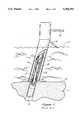
- FIG. 1is a cross-sectional elevational view of a prior art system for removing a mud plug from a casing.
- FIG. 2is a cross-sectional elevational view of a preferred embodiment of the present invention.
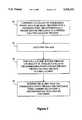
- FIG. 3is a diagram illustrating the steps of a preferred embodiment of the present invention.
- FIG. 4is a diagram illustrating the steps of an alternative embodiment of the present invention.
- FIG. 5is a diagram illustrating the steps of a second alternative embodiment of the present invention.
- offshore platforms(not shown) are anchored to the ocean floor 11 by piles 12 which are hollow casings or pipes contained within the platform legs 10.
- the platformsare further stabilized by cross-members 18.
- the piles 12are driven into the ocean floor thereby capturing the contents of the sea bed or ocean floor 11 within the pile which creates an obstruction or mud plug 16.
- the outer wall of the pileis also encased by mud.
- a prior art system 9 for removing a mud plug 16 from a casing or pile 12includes a hard, hollow pipe 20 that is provided with a ring of nozzles 22 that are coupled to a fluid pump (not shown) via fluid line 24.
- the pipe 20is further provided with an air line 26 that forces air from an air compressor (not shown) upward inside the pipe 20, as illustrated by airstream 15.
- the pipe 20is lowered inside the pile 12 and extends from a point near mud plug 16 to a point above the water line 13. Because of the weight and poor maneuverability of pipe 20, the prior art system illustrated in FIG. 1 may only be used after the upper portion of the platform is removed to expose the open platform leg 10 and pile 12, approximately 12 to 15 feet above the water. The system further requires extensive support equipment and is typically operated from a barge (not shown).
- a preferred embodiment 27 of the present inventionis provided with a submersible pump 34 having a propeller 38 or some other means for agitating the mud pile 16.
- submersible agitator pump DP-10Hmanufactured by Toyo, is used.
- a plurality of nozzles 36are coupled to a first end 29 of the submersible pump 34.
- the nozzles 36are coupled to a fluid pump (not shown) via fluid line 42.
- the submersible pump 34is lowered to a desired position adjacent mud plug 16, step 46, via winch 30 or any other feasible means.
- the pump and nozzle assemblymay be lowered into position through an opening 28 cut into a side of the platform leg 10 and casing 12.
- the opening 28may be located at any convenient point above the water line, as long as it is within the range of the submersible pump. In a preferred embodiment wherein a DP-10H pump by Toyo is used, the opening 28 may be located up to 75 feet above the water line. It is therefore not necessary to first remove the deck of the platform as is required for currently available methods.
- a volume of fluidis forced through nozzles 36 toward the mud plug, thereby diluting the mud to form a slurry, step 50.
- wateris forced through the nozzles at a rate of 600-3000 gallons per minute, and at a pressure of between 150-500 psi, with preferred results being achieved at a flow rate of 1400 gallons per minute and a pressure of 350 psi.
- This break up of the mud plug 16is further enhanced by the agitation provided by propeller 38, step 48.
- the mud and water or slurryis then pumped upward by submersible pump 34 through discharge tube 40 to the open water, step 52.
- any suitable meansfor example, spool 32, may be used to let out the various lines and keep them untangled.
- a mud plugBy removing a mud plug in accordance with the present invention, substantially all of the mud is removed, because the submersible pump 34 continues to pump and contain the mud within discharge tube 40 as pump 34 is removed from pile 12.
- prior art systemstypically leave a considerable amount of mud behind because mud that is suspended the length of the hollow pipe 20 by the air flow 15 resettles in the pile 12 as soon as the airflow 15 is no longer present.
- the method and apparatus embodying the present inventioncan remove a mud plug to a depth of 30 feet in approximately 1 hour, as compared to 6 hours by a prior art system, and are much easier and less cumbersome to use.
- Prior art systems for removing mud from adjacent or around a casinginclude sending divers down to dig the casing out.
- a submersible pump and nozzle assembly as illustrated in FIG. 2is used to excavate a hole adjacent casing 12. This is accomplished by lowering the submersible pump 34 provided with flexible discharge tube 40 to a desired location adjacent the mud and adjacent the pile 12, step 54. The mud is then agitated, step 56, and a volume of fluid, preferably water, is forced through the plurality of nozzles toward the mud to dilute the mud into a slurry, step 58. The slurry is then pumped away from the casing by the submersible pump, thereby excavating a hole adjacent the casing. After a hole is excavated to a desired depth, the submersible pump 34 may be guided to a new location adjacent the excavated hole to create a hole of any desired depth or width as may be necessary to accommodate the chosen method for removing the casing.
- a volume of fluidpreferably water
- a plurality of submersible pumpsprovided in accordance with the invention are used to excavate a circumferential hole around the casing. This is accomplished by lowering the submersible pumps in a circumferential pattern around the casing to desired locations adjacent the mud to be removed, step 62. The mud is then agitated by the pumps, step 64, and a volume of fluid is forced through a plurality of nozzles coupled to the pumps toward the mud, thereby diluting the mud to form a slurry, step 58. The mud is then pumped away from the casing by the submersible pumps, thereby excavating a circumferential hole around the casing, step 68.
Landscapes
- Engineering & Computer Science (AREA)
- General Engineering & Computer Science (AREA)
- Life Sciences & Earth Sciences (AREA)
- Structural Engineering (AREA)
- Civil Engineering (AREA)
- Mining & Mineral Resources (AREA)
- Geology (AREA)
- Environmental & Geological Engineering (AREA)
- General Life Sciences & Earth Sciences (AREA)
- Mechanical Engineering (AREA)
- Ocean & Marine Engineering (AREA)
- Fluid Mechanics (AREA)
- Physics & Mathematics (AREA)
- Geochemistry & Mineralogy (AREA)
- Paleontology (AREA)
- Earth Drilling (AREA)
- Structures Of Non-Positive Displacement Pumps (AREA)
Abstract
Description
Claims (6)
Priority Applications (1)
| Application Number | Priority Date | Filing Date | Title |
|---|---|---|---|
| US08/089,258US5360292A (en) | 1993-07-08 | 1993-07-08 | Method and apparatus for removing mud from around and inside of casings |
Applications Claiming Priority (1)
| Application Number | Priority Date | Filing Date | Title |
|---|---|---|---|
| US08/089,258US5360292A (en) | 1993-07-08 | 1993-07-08 | Method and apparatus for removing mud from around and inside of casings |
Publications (1)
| Publication Number | Publication Date |
|---|---|
| US5360292Atrue US5360292A (en) | 1994-11-01 |
Family
ID=22216604
Family Applications (1)
| Application Number | Title | Priority Date | Filing Date |
|---|---|---|---|
| US08/089,258Expired - LifetimeUS5360292A (en) | 1993-07-08 | 1993-07-08 | Method and apparatus for removing mud from around and inside of casings |
Country Status (1)
| Country | Link |
|---|---|
| US (1) | US5360292A (en) |
Cited By (71)
| Publication number | Priority date | Publication date | Assignee | Title |
|---|---|---|---|---|
| US5525010A (en)* | 1994-05-17 | 1996-06-11 | Senior Power Services, Inc., Demex Division | Method and apparatus for severing tubular members |
| US20010047866A1 (en)* | 1998-12-07 | 2001-12-06 | Cook Robert Lance | Wellbore casing |
| US20020187730A1 (en)* | 2000-08-31 | 2002-12-12 | Bristol Gordon B. | Method and apparatus for texturizing tank walls |
| US6557640B1 (en) | 1998-12-07 | 2003-05-06 | Shell Oil Company | Lubrication and self-cleaning system for expansion mandrel |
| US6568471B1 (en) | 1999-02-26 | 2003-05-27 | Shell Oil Company | Liner hanger |
| US6575250B1 (en) | 1999-11-15 | 2003-06-10 | Shell Oil Company | Expanding a tubular element in a wellbore |
| US6575240B1 (en)* | 1998-12-07 | 2003-06-10 | Shell Oil Company | System and method for driving pipe |
| US20030137183A1 (en)* | 2002-01-24 | 2003-07-24 | Kerfoot William B. | Apparatus and methods for subsidence deepening |
| US6634431B2 (en) | 1998-11-16 | 2003-10-21 | Robert Lance Cook | Isolation of subterranean zones |
| US6640903B1 (en) | 1998-12-07 | 2003-11-04 | Shell Oil Company | Forming a wellbore casing while simultaneously drilling a wellbore |
| US6672408B2 (en)* | 2001-12-03 | 2004-01-06 | Anthony F. Frantz | System and apparatus for excavating contaminated pilings |
| US6712154B2 (en) | 1998-11-16 | 2004-03-30 | Enventure Global Technology | Isolation of subterranean zones |
| US6725919B2 (en) | 1998-12-07 | 2004-04-27 | Shell Oil Company | Forming a wellbore casing while simultaneously drilling a wellbore |
| US6745845B2 (en) | 1998-11-16 | 2004-06-08 | Shell Oil Company | Isolation of subterranean zones |
| US6823937B1 (en) | 1998-12-07 | 2004-11-30 | Shell Oil Company | Wellhead |
| US6874261B2 (en)* | 1994-04-07 | 2005-04-05 | Van Oord N.V. | Method for treating an underwater bed |
| US6892819B2 (en) | 1998-12-07 | 2005-05-17 | Shell Oil Company | Forming a wellbore casing while simultaneously drilling a wellbore |
| US6968618B2 (en) | 1999-04-26 | 2005-11-29 | Shell Oil Company | Expandable connector |
| US6976541B2 (en) | 2000-09-18 | 2005-12-20 | Shell Oil Company | Liner hanger with sliding sleeve valve |
| US7011161B2 (en) | 1998-12-07 | 2006-03-14 | Shell Oil Company | Structural support |
| US7048067B1 (en) | 1999-11-01 | 2006-05-23 | Shell Oil Company | Wellbore casing repair |
| US7055608B2 (en) | 1999-03-11 | 2006-06-06 | Shell Oil Company | Forming a wellbore casing while simultaneously drilling a wellbore |
| US7100685B2 (en) | 2000-10-02 | 2006-09-05 | Enventure Global Technology | Mono-diameter wellbore casing |
| US7100684B2 (en) | 2000-07-28 | 2006-09-05 | Enventure Global Technology | Liner hanger with standoffs |
| US7121352B2 (en) | 1998-11-16 | 2006-10-17 | Enventure Global Technology | Isolation of subterranean zones |
| US7168496B2 (en) | 2001-07-06 | 2007-01-30 | Eventure Global Technology | Liner hanger |
| US7168499B2 (en) | 1998-11-16 | 2007-01-30 | Shell Oil Company | Radial expansion of tubular members |
| US7172024B2 (en) | 2000-10-02 | 2007-02-06 | Shell Oil Company | Mono-diameter wellbore casing |
| US7195064B2 (en) | 1998-12-07 | 2007-03-27 | Enventure Global Technology | Mono-diameter wellbore casing |
| US7231985B2 (en) | 1998-11-16 | 2007-06-19 | Shell Oil Company | Radial expansion of tubular members |
| US7234531B2 (en) | 1999-12-03 | 2007-06-26 | Enventure Global Technology, Llc | Mono-diameter wellbore casing |
| US7258168B2 (en) | 2001-07-27 | 2007-08-21 | Enventure Global Technology L.L.C. | Liner hanger with slip joint sealing members and method of use |
| US7290605B2 (en) | 2001-12-27 | 2007-11-06 | Enventure Global Technology | Seal receptacle using expandable liner hanger |
| US7290616B2 (en) | 2001-07-06 | 2007-11-06 | Enventure Global Technology, L.L.C. | Liner hanger |
| US7308755B2 (en) | 2003-06-13 | 2007-12-18 | Shell Oil Company | Apparatus for forming a mono-diameter wellbore casing |
| US7325602B2 (en) | 2000-10-02 | 2008-02-05 | Shell Oil Company | Method and apparatus for forming a mono-diameter wellbore casing |
| US7350564B2 (en) | 1998-12-07 | 2008-04-01 | Enventure Global Technology, L.L.C. | Mono-diameter wellbore casing |
| US7350563B2 (en) | 1999-07-09 | 2008-04-01 | Enventure Global Technology, L.L.C. | System for lining a wellbore casing |
| US7360591B2 (en) | 2002-05-29 | 2008-04-22 | Enventure Global Technology, Llc | System for radially expanding a tubular member |
| US7363984B2 (en) | 1998-12-07 | 2008-04-29 | Enventure Global Technology, Llc | System for radially expanding a tubular member |
| US7377326B2 (en) | 2002-08-23 | 2008-05-27 | Enventure Global Technology, L.L.C. | Magnetic impulse applied sleeve method of forming a wellbore casing |
| US7383889B2 (en) | 2001-11-12 | 2008-06-10 | Enventure Global Technology, Llc | Mono diameter wellbore casing |
| US7398832B2 (en) | 2002-06-10 | 2008-07-15 | Enventure Global Technology, Llc | Mono-diameter wellbore casing |
| US7404444B2 (en) | 2002-09-20 | 2008-07-29 | Enventure Global Technology | Protective sleeve for expandable tubulars |
| US7410000B2 (en) | 2001-01-17 | 2008-08-12 | Enventure Global Technology, Llc. | Mono-diameter wellbore casing |
| US7416027B2 (en) | 2001-09-07 | 2008-08-26 | Enventure Global Technology, Llc | Adjustable expansion cone assembly |
| US7424918B2 (en) | 2002-08-23 | 2008-09-16 | Enventure Global Technology, L.L.C. | Interposed joint sealing layer method of forming a wellbore casing |
| US7438133B2 (en) | 2003-02-26 | 2008-10-21 | Enventure Global Technology, Llc | Apparatus and method for radially expanding and plastically deforming a tubular member |
| US7503393B2 (en) | 2003-01-27 | 2009-03-17 | Enventure Global Technology, Inc. | Lubrication system for radially expanding tubular members |
| US7513313B2 (en) | 2002-09-20 | 2009-04-07 | Enventure Global Technology, Llc | Bottom plug for forming a mono diameter wellbore casing |
| US7516790B2 (en) | 1999-12-03 | 2009-04-14 | Enventure Global Technology, Llc | Mono-diameter wellbore casing |
| US7552776B2 (en) | 1998-12-07 | 2009-06-30 | Enventure Global Technology, Llc | Anchor hangers |
| US7571774B2 (en) | 2002-09-20 | 2009-08-11 | Eventure Global Technology | Self-lubricating expansion mandrel for expandable tubular |
| US7603758B2 (en) | 1998-12-07 | 2009-10-20 | Shell Oil Company | Method of coupling a tubular member |
| US7712522B2 (en) | 2003-09-05 | 2010-05-11 | Enventure Global Technology, Llc | Expansion cone and system |
| US7739917B2 (en) | 2002-09-20 | 2010-06-22 | Enventure Global Technology, Llc | Pipe formability evaluation for expandable tubulars |
| US7740076B2 (en) | 2002-04-12 | 2010-06-22 | Enventure Global Technology, L.L.C. | Protective sleeve for threaded connections for expandable liner hanger |
| US7775290B2 (en) | 2003-04-17 | 2010-08-17 | Enventure Global Technology, Llc | Apparatus for radially expanding and plastically deforming a tubular member |
| US7793721B2 (en) | 2003-03-11 | 2010-09-14 | Eventure Global Technology, Llc | Apparatus for radially expanding and plastically deforming a tubular member |
| US7819185B2 (en) | 2004-08-13 | 2010-10-26 | Enventure Global Technology, Llc | Expandable tubular |
| US7886831B2 (en) | 2003-01-22 | 2011-02-15 | Enventure Global Technology, L.L.C. | Apparatus for radially expanding and plastically deforming a tubular member |
| US7918284B2 (en) | 2002-04-15 | 2011-04-05 | Enventure Global Technology, L.L.C. | Protective sleeve for threaded connections for expandable liner hanger |
| WO2012030220A1 (en)* | 2010-09-01 | 2012-03-08 | Ballast Nedam Offshore B.V. | Method for introducing a hollow elongated structure into a water bottom |
| US20140064857A1 (en)* | 2012-08-30 | 2014-03-06 | Bauer Maschinen Gmbh | Guide frame for guiding a cutting apparatus |
| US20140196885A1 (en)* | 2013-01-14 | 2014-07-17 | Schlumberger Technology Corporation | Method and System for Monitoring The Incursion of Particulate Material into A Well Casing within Hydrocarbon Bearing Formations including Gas Hydrates |
| US20150007463A1 (en)* | 2013-07-08 | 2015-01-08 | Tusk Subsea Services, L.L.C. | Method and apparatus for underwater pile excavating |
| US20150330048A1 (en)* | 2014-05-19 | 2015-11-19 | Conocophillips Company | Decommissioning offshore oil and gas wells |
| WO2016067272A1 (en)* | 2014-10-31 | 2016-05-06 | D.E.C.O. Nv | Device for cutting piles |
| US10385640B2 (en) | 2017-01-10 | 2019-08-20 | Weatherford Technology Holdings, Llc | Tension cutting casing and wellhead retrieval system |
| CN110670563A (en)* | 2019-10-10 | 2020-01-10 | 中船黄埔文冲船舶有限公司 | Lifting system for self-elevating platform submersible pump |
| US11346071B2 (en)* | 2014-08-21 | 2022-05-31 | Ihc Holland Ie B.V. | Method of and system for installing foundation elements in an underwater ground formation |
Citations (26)
| Publication number | Priority date | Publication date | Assignee | Title |
|---|---|---|---|---|
| US2076823A (en)* | 1935-11-23 | 1937-04-13 | Newell Timothy | Siphon dredging pump |
| US2265082A (en)* | 1939-04-08 | 1941-12-02 | E L O Neill | Means of cutting pipe |
| US2315496A (en)* | 1938-11-28 | 1943-04-06 | Boynton Alexander | Perforator for wells |
| US3066735A (en)* | 1960-05-25 | 1962-12-04 | Dow Chemical Co | Hydraulic jetting tool |
| US3081828A (en)* | 1960-07-05 | 1963-03-19 | Thomas E Quick | Method and apparatus for producing cuts within a bore hole |
| US3145776A (en)* | 1962-07-30 | 1964-08-25 | Halliburton Co | Hydra-jet tool |
| US3153290A (en)* | 1962-01-30 | 1964-10-20 | Asia Dredging Co Ltd | Apparatus for subaqueous excavations |
| US3338305A (en)* | 1965-02-05 | 1967-08-29 | Halliburton Co | Method and apparatus for cutting casing in underwater installations |
| US3393736A (en)* | 1966-08-17 | 1968-07-23 | Gulf Research Development Co | Well completion method |
| US3585699A (en)* | 1969-05-12 | 1971-06-22 | Eugene E Shuttle | Method of connecting subterranean pipe lines |
| US3646598A (en)* | 1969-06-25 | 1972-02-29 | Bolt Associates Inc | Pile driver systems apparatus and method for driving a pile |
| US3673716A (en)* | 1968-12-20 | 1972-07-04 | Alois Trondle | Compressed air operated apparatus for raising underwater deposits |
| US4047569A (en)* | 1976-02-20 | 1977-09-13 | Kurban Magomedovich Tagirov | Method of successively opening-out and treating productive formations |
| US4223724A (en)* | 1976-12-22 | 1980-09-23 | Levoni Carlo F | Device for cleaning, widening and repairing wells of drinking water and irrigation water |
| JPS55165326A (en)* | 1979-06-08 | 1980-12-23 | Kyushu Sekisui Kogyo Kk | Pile-building machine |
| US4346761A (en)* | 1980-02-25 | 1982-08-31 | Halliburton Company | Hydra-jet slotting tool |
| US4558744A (en)* | 1982-09-14 | 1985-12-17 | Canocean Resources Ltd. | Subsea caisson and method of installing same |
| US4575282A (en)* | 1984-06-04 | 1986-03-11 | Pardue Sr James H | System for driving open end pipe piles on the ocean floor using pneumatic evacuation and existing hydrostatic pressure |
| US4619556A (en)* | 1983-11-14 | 1986-10-28 | Parra Ernest P | Method and apparatus for severing a tubular member |
| US4768899A (en)* | 1987-04-20 | 1988-09-06 | Dysarz Edward D | Device and method to cut piles |
| US4808037A (en)* | 1987-02-25 | 1989-02-28 | Franklin C. Wade | Method and apparatus for removal of submerged offshore objects |
| JPH02164915A (en)* | 1988-12-16 | 1990-06-25 | Shimizu Corp | Foundation pile driving method |
| SU1613616A1 (en)* | 1988-09-19 | 1990-12-15 | Горьковский Институт Инженеров Водного Транспорта | Soil intake of suction dridger |
| US5002434A (en)* | 1988-09-02 | 1991-03-26 | Darya Paye Jetty Co., Ltd. | Method and apparatus for placing a hollow column in the hard bottom of a body of water in particular in a rock bottom |
| US5001870A (en)* | 1987-10-05 | 1991-03-26 | Kajima Corporation | Method of cutting and disassembling cylindrical structure |
| US5010694A (en)* | 1989-08-01 | 1991-04-30 | Advanced Technology Systems, Inc. | Fluid cutting machine |
- 1993
- 1993-07-08USUS08/089,258patent/US5360292A/ennot_activeExpired - Lifetime
Patent Citations (26)
| Publication number | Priority date | Publication date | Assignee | Title |
|---|---|---|---|---|
| US2076823A (en)* | 1935-11-23 | 1937-04-13 | Newell Timothy | Siphon dredging pump |
| US2315496A (en)* | 1938-11-28 | 1943-04-06 | Boynton Alexander | Perforator for wells |
| US2265082A (en)* | 1939-04-08 | 1941-12-02 | E L O Neill | Means of cutting pipe |
| US3066735A (en)* | 1960-05-25 | 1962-12-04 | Dow Chemical Co | Hydraulic jetting tool |
| US3081828A (en)* | 1960-07-05 | 1963-03-19 | Thomas E Quick | Method and apparatus for producing cuts within a bore hole |
| US3153290A (en)* | 1962-01-30 | 1964-10-20 | Asia Dredging Co Ltd | Apparatus for subaqueous excavations |
| US3145776A (en)* | 1962-07-30 | 1964-08-25 | Halliburton Co | Hydra-jet tool |
| US3338305A (en)* | 1965-02-05 | 1967-08-29 | Halliburton Co | Method and apparatus for cutting casing in underwater installations |
| US3393736A (en)* | 1966-08-17 | 1968-07-23 | Gulf Research Development Co | Well completion method |
| US3673716A (en)* | 1968-12-20 | 1972-07-04 | Alois Trondle | Compressed air operated apparatus for raising underwater deposits |
| US3585699A (en)* | 1969-05-12 | 1971-06-22 | Eugene E Shuttle | Method of connecting subterranean pipe lines |
| US3646598A (en)* | 1969-06-25 | 1972-02-29 | Bolt Associates Inc | Pile driver systems apparatus and method for driving a pile |
| US4047569A (en)* | 1976-02-20 | 1977-09-13 | Kurban Magomedovich Tagirov | Method of successively opening-out and treating productive formations |
| US4223724A (en)* | 1976-12-22 | 1980-09-23 | Levoni Carlo F | Device for cleaning, widening and repairing wells of drinking water and irrigation water |
| JPS55165326A (en)* | 1979-06-08 | 1980-12-23 | Kyushu Sekisui Kogyo Kk | Pile-building machine |
| US4346761A (en)* | 1980-02-25 | 1982-08-31 | Halliburton Company | Hydra-jet slotting tool |
| US4558744A (en)* | 1982-09-14 | 1985-12-17 | Canocean Resources Ltd. | Subsea caisson and method of installing same |
| US4619556A (en)* | 1983-11-14 | 1986-10-28 | Parra Ernest P | Method and apparatus for severing a tubular member |
| US4575282A (en)* | 1984-06-04 | 1986-03-11 | Pardue Sr James H | System for driving open end pipe piles on the ocean floor using pneumatic evacuation and existing hydrostatic pressure |
| US4808037A (en)* | 1987-02-25 | 1989-02-28 | Franklin C. Wade | Method and apparatus for removal of submerged offshore objects |
| US4768899A (en)* | 1987-04-20 | 1988-09-06 | Dysarz Edward D | Device and method to cut piles |
| US5001870A (en)* | 1987-10-05 | 1991-03-26 | Kajima Corporation | Method of cutting and disassembling cylindrical structure |
| US5002434A (en)* | 1988-09-02 | 1991-03-26 | Darya Paye Jetty Co., Ltd. | Method and apparatus for placing a hollow column in the hard bottom of a body of water in particular in a rock bottom |
| SU1613616A1 (en)* | 1988-09-19 | 1990-12-15 | Горьковский Институт Инженеров Водного Транспорта | Soil intake of suction dridger |
| JPH02164915A (en)* | 1988-12-16 | 1990-06-25 | Shimizu Corp | Foundation pile driving method |
| US5010694A (en)* | 1989-08-01 | 1991-04-30 | Advanced Technology Systems, Inc. | Fluid cutting machine |
Non-Patent Citations (2)
| Title |
|---|
| Brochure: "All Pumps Were Not Created Equal", Toyo Pumps, Published: 1987. |
| Brochure: All Pumps Were Not Created Equal , Toyo Pumps, Published: 1987.* |
Cited By (126)
| Publication number | Priority date | Publication date | Assignee | Title |
|---|---|---|---|---|
| US6874261B2 (en)* | 1994-04-07 | 2005-04-05 | Van Oord N.V. | Method for treating an underwater bed |
| US5525010A (en)* | 1994-05-17 | 1996-06-11 | Senior Power Services, Inc., Demex Division | Method and apparatus for severing tubular members |
| US7275601B2 (en) | 1998-11-16 | 2007-10-02 | Shell Oil Company | Radial expansion of tubular members |
| US6634431B2 (en) | 1998-11-16 | 2003-10-21 | Robert Lance Cook | Isolation of subterranean zones |
| US7168499B2 (en) | 1998-11-16 | 2007-01-30 | Shell Oil Company | Radial expansion of tubular members |
| US7299881B2 (en) | 1998-11-16 | 2007-11-27 | Shell Oil Company | Radial expansion of tubular members |
| US7121352B2 (en) | 1998-11-16 | 2006-10-17 | Enventure Global Technology | Isolation of subterranean zones |
| US7108072B2 (en) | 1998-11-16 | 2006-09-19 | Shell Oil Company | Lubrication and self-cleaning system for expansion mandrel |
| US7357190B2 (en) | 1998-11-16 | 2008-04-15 | Shell Oil Company | Radial expansion of tubular members |
| US7270188B2 (en) | 1998-11-16 | 2007-09-18 | Shell Oil Company | Radial expansion of tubular members |
| US7246667B2 (en) | 1998-11-16 | 2007-07-24 | Shell Oil Company | Radial expansion of tubular members |
| US6745845B2 (en) | 1998-11-16 | 2004-06-08 | Shell Oil Company | Isolation of subterranean zones |
| US6712154B2 (en) | 1998-11-16 | 2004-03-30 | Enventure Global Technology | Isolation of subterranean zones |
| US7231985B2 (en) | 1998-11-16 | 2007-06-19 | Shell Oil Company | Radial expansion of tubular members |
| US7552776B2 (en) | 1998-12-07 | 2009-06-30 | Enventure Global Technology, Llc | Anchor hangers |
| US7147053B2 (en) | 1998-12-07 | 2006-12-12 | Shell Oil Company | Wellhead |
| US7216701B2 (en) | 1998-12-07 | 2007-05-15 | Shell Oil Company | Apparatus for expanding a tubular member |
| US7240729B2 (en) | 1998-12-07 | 2007-07-10 | Shell Oil Company | Apparatus for expanding a tubular member |
| US7240728B2 (en) | 1998-12-07 | 2007-07-10 | Shell Oil Company | Expandable tubulars with a radial passage and wall portions with different wall thicknesses |
| US7198100B2 (en) | 1998-12-07 | 2007-04-03 | Shell Oil Company | Apparatus for expanding a tubular member |
| US6631760B2 (en) | 1998-12-07 | 2003-10-14 | Shell Oil Company | Tie back liner for a well system |
| US6725919B2 (en) | 1998-12-07 | 2004-04-27 | Shell Oil Company | Forming a wellbore casing while simultaneously drilling a wellbore |
| US6739392B2 (en) | 1998-12-07 | 2004-05-25 | Shell Oil Company | Forming a wellbore casing while simultaneously drilling a wellbore |
| US7195061B2 (en) | 1998-12-07 | 2007-03-27 | Shell Oil Company | Apparatus for expanding a tubular member |
| US6758278B2 (en) | 1998-12-07 | 2004-07-06 | Shell Oil Company | Forming a wellbore casing while simultaneously drilling a wellbore |
| US7434618B2 (en) | 1998-12-07 | 2008-10-14 | Shell Oil Company | Apparatus for expanding a tubular member |
| US6823937B1 (en) | 1998-12-07 | 2004-11-30 | Shell Oil Company | Wellhead |
| US7195064B2 (en) | 1998-12-07 | 2007-03-27 | Enventure Global Technology | Mono-diameter wellbore casing |
| US7174964B2 (en) | 1998-12-07 | 2007-02-13 | Shell Oil Company | Wellhead with radially expanded tubulars |
| US6892819B2 (en) | 1998-12-07 | 2005-05-17 | Shell Oil Company | Forming a wellbore casing while simultaneously drilling a wellbore |
| US20010047866A1 (en)* | 1998-12-07 | 2001-12-06 | Cook Robert Lance | Wellbore casing |
| US6575240B1 (en)* | 1998-12-07 | 2003-06-10 | Shell Oil Company | System and method for driving pipe |
| US7419009B2 (en) | 1998-12-07 | 2008-09-02 | Shell Oil Company | Apparatus for radially expanding and plastically deforming a tubular member |
| US7011161B2 (en) | 1998-12-07 | 2006-03-14 | Shell Oil Company | Structural support |
| US7036582B2 (en) | 1998-12-07 | 2006-05-02 | Shell Oil Company | Expansion cone for radially expanding tubular members |
| US6470966B2 (en) | 1998-12-07 | 2002-10-29 | Robert Lance Cook | Apparatus for forming wellbore casing |
| US7044218B2 (en) | 1998-12-07 | 2006-05-16 | Shell Oil Company | Apparatus for radially expanding tubular members |
| US7665532B2 (en) | 1998-12-07 | 2010-02-23 | Shell Oil Company | Pipeline |
| US7048062B2 (en) | 1998-12-07 | 2006-05-23 | Shell Oil Company | Method of selecting tubular members |
| US7363984B2 (en) | 1998-12-07 | 2008-04-29 | Enventure Global Technology, Llc | System for radially expanding a tubular member |
| US6497289B1 (en) | 1998-12-07 | 2002-12-24 | Robert Lance Cook | Method of creating a casing in a borehole |
| US6557640B1 (en) | 1998-12-07 | 2003-05-06 | Shell Oil Company | Lubrication and self-cleaning system for expansion mandrel |
| US7077211B2 (en) | 1998-12-07 | 2006-07-18 | Shell Oil Company | Method of creating a casing in a borehole |
| US7077213B2 (en) | 1998-12-07 | 2006-07-18 | Shell Oil Company | Expansion cone for radially expanding tubular members |
| US7603758B2 (en) | 1998-12-07 | 2009-10-20 | Shell Oil Company | Method of coupling a tubular member |
| US7357188B1 (en) | 1998-12-07 | 2008-04-15 | Shell Oil Company | Mono-diameter wellbore casing |
| US7108061B2 (en) | 1998-12-07 | 2006-09-19 | Shell Oil Company | Expander for a tapered liner with a shoe |
| US7159665B2 (en) | 1998-12-07 | 2007-01-09 | Shell Oil Company | Wellbore casing |
| US6561227B2 (en) | 1998-12-07 | 2003-05-13 | Shell Oil Company | Wellbore casing |
| US7121337B2 (en) | 1998-12-07 | 2006-10-17 | Shell Oil Company | Apparatus for expanding a tubular member |
| US7350564B2 (en) | 1998-12-07 | 2008-04-01 | Enventure Global Technology, L.L.C. | Mono-diameter wellbore casing |
| US6640903B1 (en) | 1998-12-07 | 2003-11-04 | Shell Oil Company | Forming a wellbore casing while simultaneously drilling a wellbore |
| US7159667B2 (en) | 1999-02-25 | 2007-01-09 | Shell Oil Company | Method of coupling a tubular member to a preexisting structure |
| US6631769B2 (en) | 1999-02-26 | 2003-10-14 | Shell Oil Company | Method of operating an apparatus for radially expanding a tubular member |
| US7063142B2 (en) | 1999-02-26 | 2006-06-20 | Shell Oil Company | Method of applying an axial force to an expansion cone |
| US7044221B2 (en) | 1999-02-26 | 2006-05-16 | Shell Oil Company | Apparatus for coupling a tubular member to a preexisting structure |
| US7040396B2 (en) | 1999-02-26 | 2006-05-09 | Shell Oil Company | Apparatus for releasably coupling two elements |
| US6966370B2 (en) | 1999-02-26 | 2005-11-22 | Shell Oil Company | Apparatus for actuating an annular piston |
| US7556092B2 (en) | 1999-02-26 | 2009-07-07 | Enventure Global Technology, Llc | Flow control system for an apparatus for radially expanding tubular members |
| US6857473B2 (en) | 1999-02-26 | 2005-02-22 | Shell Oil Company | Method of coupling a tubular member to a preexisting structure |
| US6568471B1 (en) | 1999-02-26 | 2003-05-27 | Shell Oil Company | Liner hanger |
| US6705395B2 (en) | 1999-02-26 | 2004-03-16 | Shell Oil Company | Wellbore casing |
| US6684947B2 (en) | 1999-02-26 | 2004-02-03 | Shell Oil Company | Apparatus for radially expanding a tubular member |
| US6631759B2 (en) | 1999-02-26 | 2003-10-14 | Shell Oil Company | Apparatus for radially expanding a tubular member |
| US7055608B2 (en) | 1999-03-11 | 2006-06-06 | Shell Oil Company | Forming a wellbore casing while simultaneously drilling a wellbore |
| US7438132B2 (en) | 1999-03-11 | 2008-10-21 | Shell Oil Company | Concentric pipes expanded at the pipe ends and method of forming |
| US6968618B2 (en) | 1999-04-26 | 2005-11-29 | Shell Oil Company | Expandable connector |
| US7350563B2 (en) | 1999-07-09 | 2008-04-01 | Enventure Global Technology, L.L.C. | System for lining a wellbore casing |
| US7048067B1 (en) | 1999-11-01 | 2006-05-23 | Shell Oil Company | Wellbore casing repair |
| US6575250B1 (en) | 1999-11-15 | 2003-06-10 | Shell Oil Company | Expanding a tubular element in a wellbore |
| US7516790B2 (en) | 1999-12-03 | 2009-04-14 | Enventure Global Technology, Llc | Mono-diameter wellbore casing |
| US7234531B2 (en) | 1999-12-03 | 2007-06-26 | Enventure Global Technology, Llc | Mono-diameter wellbore casing |
| US7100684B2 (en) | 2000-07-28 | 2006-09-05 | Enventure Global Technology | Liner hanger with standoffs |
| US20020187730A1 (en)* | 2000-08-31 | 2002-12-12 | Bristol Gordon B. | Method and apparatus for texturizing tank walls |
| US6675548B2 (en) | 2000-08-31 | 2004-01-13 | Dyk Incorporated | Method and apparatus for texturizing tank walls |
| US6976541B2 (en) | 2000-09-18 | 2005-12-20 | Shell Oil Company | Liner hanger with sliding sleeve valve |
| US7172021B2 (en) | 2000-09-18 | 2007-02-06 | Shell Oil Company | Liner hanger with sliding sleeve valve |
| US7172024B2 (en) | 2000-10-02 | 2007-02-06 | Shell Oil Company | Mono-diameter wellbore casing |
| US7172019B2 (en) | 2000-10-02 | 2007-02-06 | Shell Oil Company | Method and apparatus for forming a mono-diameter wellbore casing |
| US7146702B2 (en) | 2000-10-02 | 2006-12-12 | Shell Oil Company | Method and apparatus for forming a mono-diameter wellbore casing |
| US7204007B2 (en) | 2000-10-02 | 2007-04-17 | Shell Oil Company | Method and apparatus for forming a mono-diameter wellbore casing |
| US7201223B2 (en) | 2000-10-02 | 2007-04-10 | Shell Oil Company | Method and apparatus for forming a mono-diameter wellbore casing |
| US7100685B2 (en) | 2000-10-02 | 2006-09-05 | Enventure Global Technology | Mono-diameter wellbore casing |
| US7325602B2 (en) | 2000-10-02 | 2008-02-05 | Shell Oil Company | Method and apparatus for forming a mono-diameter wellbore casing |
| US7363691B2 (en) | 2000-10-02 | 2008-04-29 | Shell Oil Company | Method and apparatus for forming a mono-diameter wellbore casing |
| US7363690B2 (en) | 2000-10-02 | 2008-04-29 | Shell Oil Company | Method and apparatus for forming a mono-diameter wellbore casing |
| US7410000B2 (en) | 2001-01-17 | 2008-08-12 | Enventure Global Technology, Llc. | Mono-diameter wellbore casing |
| US7290616B2 (en) | 2001-07-06 | 2007-11-06 | Enventure Global Technology, L.L.C. | Liner hanger |
| US7168496B2 (en) | 2001-07-06 | 2007-01-30 | Eventure Global Technology | Liner hanger |
| US7258168B2 (en) | 2001-07-27 | 2007-08-21 | Enventure Global Technology L.L.C. | Liner hanger with slip joint sealing members and method of use |
| US7416027B2 (en) | 2001-09-07 | 2008-08-26 | Enventure Global Technology, Llc | Adjustable expansion cone assembly |
| US7383889B2 (en) | 2001-11-12 | 2008-06-10 | Enventure Global Technology, Llc | Mono diameter wellbore casing |
| US7559365B2 (en) | 2001-11-12 | 2009-07-14 | Enventure Global Technology, Llc | Collapsible expansion cone |
| US6672408B2 (en)* | 2001-12-03 | 2004-01-06 | Anthony F. Frantz | System and apparatus for excavating contaminated pilings |
| US7290605B2 (en) | 2001-12-27 | 2007-11-06 | Enventure Global Technology | Seal receptacle using expandable liner hanger |
| US6817119B2 (en)* | 2002-01-24 | 2004-11-16 | William B. Kerfoot | Apparatus and methods for subsidence deepening |
| US20030137183A1 (en)* | 2002-01-24 | 2003-07-24 | Kerfoot William B. | Apparatus and methods for subsidence deepening |
| US7740076B2 (en) | 2002-04-12 | 2010-06-22 | Enventure Global Technology, L.L.C. | Protective sleeve for threaded connections for expandable liner hanger |
| US7918284B2 (en) | 2002-04-15 | 2011-04-05 | Enventure Global Technology, L.L.C. | Protective sleeve for threaded connections for expandable liner hanger |
| US7360591B2 (en) | 2002-05-29 | 2008-04-22 | Enventure Global Technology, Llc | System for radially expanding a tubular member |
| US7398832B2 (en) | 2002-06-10 | 2008-07-15 | Enventure Global Technology, Llc | Mono-diameter wellbore casing |
| US7377326B2 (en) | 2002-08-23 | 2008-05-27 | Enventure Global Technology, L.L.C. | Magnetic impulse applied sleeve method of forming a wellbore casing |
| US7424918B2 (en) | 2002-08-23 | 2008-09-16 | Enventure Global Technology, L.L.C. | Interposed joint sealing layer method of forming a wellbore casing |
| US7404444B2 (en) | 2002-09-20 | 2008-07-29 | Enventure Global Technology | Protective sleeve for expandable tubulars |
| US7513313B2 (en) | 2002-09-20 | 2009-04-07 | Enventure Global Technology, Llc | Bottom plug for forming a mono diameter wellbore casing |
| US7571774B2 (en) | 2002-09-20 | 2009-08-11 | Eventure Global Technology | Self-lubricating expansion mandrel for expandable tubular |
| US7739917B2 (en) | 2002-09-20 | 2010-06-22 | Enventure Global Technology, Llc | Pipe formability evaluation for expandable tubulars |
| US7886831B2 (en) | 2003-01-22 | 2011-02-15 | Enventure Global Technology, L.L.C. | Apparatus for radially expanding and plastically deforming a tubular member |
| US7503393B2 (en) | 2003-01-27 | 2009-03-17 | Enventure Global Technology, Inc. | Lubrication system for radially expanding tubular members |
| US7438133B2 (en) | 2003-02-26 | 2008-10-21 | Enventure Global Technology, Llc | Apparatus and method for radially expanding and plastically deforming a tubular member |
| US7793721B2 (en) | 2003-03-11 | 2010-09-14 | Eventure Global Technology, Llc | Apparatus for radially expanding and plastically deforming a tubular member |
| US7775290B2 (en) | 2003-04-17 | 2010-08-17 | Enventure Global Technology, Llc | Apparatus for radially expanding and plastically deforming a tubular member |
| US7308755B2 (en) | 2003-06-13 | 2007-12-18 | Shell Oil Company | Apparatus for forming a mono-diameter wellbore casing |
| US7712522B2 (en) | 2003-09-05 | 2010-05-11 | Enventure Global Technology, Llc | Expansion cone and system |
| US7819185B2 (en) | 2004-08-13 | 2010-10-26 | Enventure Global Technology, Llc | Expandable tubular |
| WO2012030220A1 (en)* | 2010-09-01 | 2012-03-08 | Ballast Nedam Offshore B.V. | Method for introducing a hollow elongated structure into a water bottom |
| US9297137B2 (en)* | 2012-08-30 | 2016-03-29 | Bauer Maschinen Gmbh | Guide frame for guiding a cutting apparatus |
| US20140064857A1 (en)* | 2012-08-30 | 2014-03-06 | Bauer Maschinen Gmbh | Guide frame for guiding a cutting apparatus |
| US20140196885A1 (en)* | 2013-01-14 | 2014-07-17 | Schlumberger Technology Corporation | Method and System for Monitoring The Incursion of Particulate Material into A Well Casing within Hydrocarbon Bearing Formations including Gas Hydrates |
| US20150007463A1 (en)* | 2013-07-08 | 2015-01-08 | Tusk Subsea Services, L.L.C. | Method and apparatus for underwater pile excavating |
| US20150330048A1 (en)* | 2014-05-19 | 2015-11-19 | Conocophillips Company | Decommissioning offshore oil and gas wells |
| US9366091B2 (en)* | 2014-05-19 | 2016-06-14 | Conocophillips Company | Decommissioning offshore oil and gas wells |
| US11346071B2 (en)* | 2014-08-21 | 2022-05-31 | Ihc Holland Ie B.V. | Method of and system for installing foundation elements in an underwater ground formation |
| WO2016067272A1 (en)* | 2014-10-31 | 2016-05-06 | D.E.C.O. Nv | Device for cutting piles |
| US10385640B2 (en) | 2017-01-10 | 2019-08-20 | Weatherford Technology Holdings, Llc | Tension cutting casing and wellhead retrieval system |
| CN110670563A (en)* | 2019-10-10 | 2020-01-10 | 中船黄埔文冲船舶有限公司 | Lifting system for self-elevating platform submersible pump |
Similar Documents
| Publication | Publication Date | Title |
|---|---|---|
| US5360292A (en) | Method and apparatus for removing mud from around and inside of casings | |
| US4432671A (en) | Suction anchor and method of installing a suction anchor | |
| US4558744A (en) | Subsea caisson and method of installing same | |
| CN109025880B (en) | A kind of deposit core-drilling technique suitable for seabed wire line coring drilling machine | |
| US4619556A (en) | Method and apparatus for severing a tubular member | |
| US7647712B2 (en) | Cutter head for dredging soil and method for dredging by means of this cutter head | |
| EP1210499B1 (en) | Method and system for processing of drilling fluid | |
| US6203248B1 (en) | Sliding-resistant bottom-founded offshore structures | |
| WO1993009369A1 (en) | Gravel-packed pipeline and method and apparatus for installation thereof | |
| US4334584A (en) | Method and apparatus for installing a sea-floor cellar in a subsea bottom having compacted soil conditions | |
| US4217709A (en) | Submarine sand sampler | |
| CN106400805A (en) | Construction method for pile bottom hole cleaning of pile foundation construction | |
| US4189255A (en) | Sea-floor shoring cellar and method of installing same | |
| JP3330251B2 (en) | Underwater sludge removal equipment | |
| EP3277891B1 (en) | Method of operating a pile driving assembly | |
| CN115142815A (en) | Underwater drilling solid waste cleaning system, drilling and cementing operation system and method thereof | |
| US12055041B2 (en) | Apparatus and method for removing soil from a conduit | |
| GB2371067A (en) | Vehicle for dredging beneath a drilling platform | |
| US3964543A (en) | Underwater wellhead completions with portable atmospheric cellar | |
| JP7576268B2 (en) | System and method for collecting underwater resources | |
| US20180171722A1 (en) | Well drilling system | |
| GB2355746A (en) | Device and method for removing sediment | |
| JPH07247553A (en) | Groundwater pumping equipment | |
| JPS62189225A (en) | Sand collecting ship | |
| CA1155308A (en) | Method and apparatus for installing a sea-floor cellar in a subsea bottom having compacted soil conditions |
Legal Events
| Date | Code | Title | Description |
|---|---|---|---|
| AS | Assignment | Owner name:FLOW INTERNATIONAL CORPORATION, WASHINGTON Free format text:ASSIGNMENT OF ASSIGNORS INTEREST;ASSIGNORS:ALLEN, JAMES R.;LALANDE, ALTON JAMES;REEL/FRAME:006620/0156 Effective date:19930706 | |
| STPP | Information on status: patent application and granting procedure in general | Free format text:APPLICATION UNDERGOING PREEXAM PROCESSING | |
| FEPP | Fee payment procedure | Free format text:PAYOR NUMBER ASSIGNED (ORIGINAL EVENT CODE: ASPN); ENTITY STATUS OF PATENT OWNER: LARGE ENTITY | |
| FPAY | Fee payment | Year of fee payment:4 | |
| AS | Assignment | Owner name:BANK OF AMERICA NATIONAL TRUST AND SAVINGS ASSOCIA Free format text:SECURITY AGREEMENT;ASSIGNOR:FLOW INTERNATIONAL CORPORATION;REEL/FRAME:009525/0204 Effective date:19980831 | |
| FPAY | Fee payment | Year of fee payment:8 | |
| REMI | Maintenance fee reminder mailed | ||
| AS | Assignment | Owner name:JOHN HANCOCK LIFE INSURANCE COMPANY, AS COLLATERAL Free format text:SECURITY INTEREST;ASSIGNOR:FLOW INTERNATIONAL CORPORATION;REEL/FRAME:013447/0301 Effective date:20021001 | |
| AS | Assignment | Owner name:FLOW INTERNATIONAL CORPORATION, WASHINGTON Free format text:ASSIGNMENT OF ASSIGNORS INTEREST;ASSIGNOR:BANK OF AMERICA, N.A.;REEL/FRAME:013684/0475 Effective date:20030522 | |
| AS | Assignment | Owner name:UWG GROUP, INC., UNITED KINGDOM Free format text:ASSIGNMENT OF ASSIGNORS INTEREST;ASSIGNOR:FLOW INTERNATIONAL CORPORATION;REEL/FRAME:014108/0876 Effective date:20030509 | |
| AS | Assignment | Owner name:FLOW INTERNATIONAL CORPORATION, WASHINGTON Free format text:RELEASE OF SECURITY AGREEMENT;ASSIGNOR:BANK OF AMERICA, N.A.;REEL/FRAME:013922/0675 Effective date:20030523 | |
| AS | Assignment | Owner name:BANK OF AMERICA, N.A.,WASHINGTON Free format text:SECURITY AGREEMENT;ASSIGNOR:FLOW INTERNATIONAL CORPORATION;REEL/FRAME:016283/0522 Effective date:20050708 Owner name:BANK OF AMERICA, N.A., WASHINGTON Free format text:SECURITY AGREEMENT;ASSIGNOR:FLOW INTERNATIONAL CORPORATION;REEL/FRAME:016283/0522 Effective date:20050708 | |
| AS | Assignment | Owner name:FLOW INTERNATIONAL CORPORATION, WASHINGTON Free format text:RELEASE BY SECURED PARTY;ASSIGNOR:BANK OF AMERICA, N.A.;REEL/FRAME:016745/0842 Effective date:20051031 | |
| AS | Assignment | Owner name:FLOW INTERNATIONAL CORPORATION, WASHINGTON Free format text:RELEASE BY SECURED PARTY;ASSIGNOR:JOHN HANCOCK LIFE INSURANCE COMPANY;REEL/FRAME:016761/0670 Effective date:20051031 | |
| FPAY | Fee payment | Year of fee payment:12 | |
| AS | Assignment | Owner name:BANK OF AMERICA, N.A., WASHINGTON Free format text:SECURITY AGREEMENT;ASSIGNOR:FLOW INTERNATIONAL CORPORATION;REEL/FRAME:021138/0738 Effective date:20080609 Owner name:BANK OF AMERICA, N.A.,WASHINGTON Free format text:SECURITY AGREEMENT;ASSIGNOR:FLOW INTERNATIONAL CORPORATION;REEL/FRAME:021138/0738 Effective date:20080609 | |
| AS | Assignment | Owner name:BANK OF AMERICA, N.A., WASHINGTON Free format text:NOTICE OF GRANT OF SECURITY INTEREST;ASSIGNOR:FLOW INTERNATIONAL CORPORATION;REEL/FRAME:022813/0733 Effective date:20090610 Owner name:BANK OF AMERICA, N.A.,WASHINGTON Free format text:NOTICE OF GRANT OF SECURITY INTEREST;ASSIGNOR:FLOW INTERNATIONAL CORPORATION;REEL/FRAME:022813/0733 Effective date:20090610 | |
| AS | Assignment | Owner name:INTERMOOR INC., LOUISIANA Free format text:MERGER;ASSIGNOR:UWG GROUP, INC.;REEL/FRAME:028312/0066 Effective date:20080319 | |
| AS | Assignment | Owner name:FLOW INTERNATIONAL CORPORATION, WASHINGTON Free format text:RELEASE BY SECURED PARTY;ASSIGNOR:BANK OF AMERICA, N.A.;REEL/FRAME:030628/0562 Effective date:20130531 |