US5360150A - Roof rack for vehicles - Google Patents
Roof rack for vehiclesDownload PDFInfo
- Publication number
- US5360150A US5360150AUS08/054,739US5473993AUS5360150AUS 5360150 AUS5360150 AUS 5360150AUS 5473993 AUS5473993 AUS 5473993AUS 5360150 AUS5360150 AUS 5360150A
- Authority
- US
- United States
- Prior art keywords
- roof rack
- support
- rack according
- guide portion
- stationary
- Prior art date
- Legal status (The legal status is an assumption and is not a legal conclusion. Google has not performed a legal analysis and makes no representation as to the accuracy of the status listed.)
- Expired - Lifetime
Links
Images


Classifications
- B—PERFORMING OPERATIONS; TRANSPORTING
- B60—VEHICLES IN GENERAL
- B60R—VEHICLES, VEHICLE FITTINGS, OR VEHICLE PARTS, NOT OTHERWISE PROVIDED FOR
- B60R9/00—Supplementary fittings on vehicle exterior for carrying loads, e.g. luggage, sports gear or the like
- B60R9/04—Carriers associated with vehicle roof
- B60R9/042—Carriers characterised by means to facilitate loading or unloading of the load, e.g. rollers, tracks, or the like
Definitions
- the present inventionrelates to a roof rack device for an automobile comprising a supporting bar which comprises fixation means for the load to be supported by said roof rack.
- roof rack devicesare actually known to be used on the roofs of motor vehicles such as ski racks, simple support bars, etc. which are disposed on the roof of an automobile whereby the legs of these devices engage the rain gutter of the roof of the car in order to maintain the device in its position on the roof of the car.
- Other systemsare also know which are specially conceived for utilization on the roof of cars which do not have rain gutters, whereby these support racks comprise generally support legs which abut on the roof of the car as well as independent fixation means which snugly fit into the profile of the opening of the car door.
- a luggage rackhas been proposed which comprises a mechanism that permits lowering the fixation elements of this device laterally of the car in order to more easily access the fixation elements. This downwards movement is effectuated by pivoting certain levers which results, however, also in a pivoting movement of the load.
- the device according to this Swiss patentrequires the mounting of the load on the lowered portions of the support rack in a pivoted position and on a non-horizontal surface, which is of course an important inconvenience and which renders the various manipulations rather difficult.
- the present inventiontherefore has the objective to facilitate the mounting of the load on a support rack for vehicles such as described above.
- a support rackwhich is characterized in that said support bar comprises a stationary longitudinal element, adapted to be mounted across the roof of a vehicle, in essentially horizontal position, and at least one mobile element, able to slide in horizontal fashion and in longitudinal relationship with respect to said stationary element between a home position and an extended position, whereby said mobile element comprises a guide portion for guiding the horizontal sliding, and a support portion which is adapted to execute a movement having a vertical component, whereby said support portion is adapted so as to maintain a horizontal orientation during its vertical movement, said guide portion cooperating with said stationary element in a manner as to permit the execution of said vertical movement when said mobile element is extended essentially until its extended position, said support portion being in an elevated position when located in its home position as well as during the horizontal sliding movement of the mobile element, said support portion being capable of being lowered during the vertical movement.
- a support rack according to the present inventionpermits positioning the support portion laterally of the car and at an intermediary height such as to permit the user to fasten the load on the support portion without being obliged to access components of the device which are located above the roof of the vehicle, thus permitting execution these manipulations at a convenient height.
- the lowering and raising of the support portion and its movement toward the home position as well as its fixation on the support barmay be effectuated by a combination of horizontal and vertical movements of the support portion after fixation of the load in a position which provides ease of such manipulations.
- the support rack as mentioned hereinabovemay include a latch provided to lock the mobile element in its home position in order to guarantee the security of the load above the roof during the movement of the car.
- the stationary elementmay comprise a tubular shape adapted such as to receive in its interior the guiding portion of the mobile element, said guiding portion being adapted to slide therewithin and along the stationary element.
- the mobile elementmay be in the shape of a crank having two parallel portions which are offset one with respect to the other and an intermediary transversal portion connecting the two ends of the parallel portions opposing each other, one of these two parallel portions serving as said guide portion and being received within the interior of the stationary element such as to permit a rotating movement and a translatory movement in a longitudinal direction with respect to the stationary element.
- the stationary tubular elementmay comprise a longitudinal slot which permits the transversal intermediary portion to exit from the interior of the fixed tubular element and to move the mobile element in longitudinal direction with respect to the stationary element, whereby the transversal intermediary portion of the mobile element slides within said slot in longitudinal direction.
- the guiding portionmay comprise a slide having a vertical dimension of sufficient extension to permit the pivoting connection to said slide of first ends of two parallel and vertically distant rods, such as to create a vertical distance between them, the other ends of these rods being connected to the support portion of the mobile element at two pivoting fixation points which are equally separated from each other by said vertical distance.
- the guide portionmay also consist of a bar which is connected to the support portion by two rods whereof the fixation points are situated longitudinally (or horizontally) offset on the support portion and the guide portion.
- the stationary elementmay also be of tubular shape and house the slide in a fashion such as to be mobile in longitudinal direction.
- the mobile element of this embodimenti.e. the support portion, the parallel rods and the slide are all aligned within the interior of the tubular stationary element.
- the stationary tubular elementmay also comprise a longitudinal slot which is located laterally or along a superior portion of said stationary element, whereby this slot is adapted to permit the passage of fixation means for the load from the interior of said tubular element to the exterior thereof, when said support portion is located within the interior of said stationary tubular element.
- the support portion of the mobile elementmay comprise a handle which permits seizing the mobile element in order to move said mobile element between its home position and its extended position.
- the mobile elementmay comprise telescopic portions which permit an elongation of the support portion.
- the parallel rodsmay also comprise telescopic portions which permit their elongation.
- the support rack according to the present inventionmay comprise two parallel stationary elements which are connected to each other, whereby each includes a mobile element and the two mobile elements may be disposed such as to be extensible on opposite sides of the vehicle.
- the support rack according to the present inventionmay comprise two simple support bars or two assemblies of two support bars each such as described in the preceeding paragraph, whereby the two simple bars or the two assemblies of double bars are parallel and offset from each other, whereby the support portions which are situated at the same side of the vehicle are connected to each other by at least one support rail.
- FIG. 1illustrates a support rack for a vehicle according to the present invention in its home position
- FIG. 2illustrates the same device as FIG. 1 in its extended position
- FIG. 3is a longitudinal sectional view of a support rack according to the present invention in its home position
- FIG. 4illustrates a longitudinal sectional view of the same support bar as FIG. 3 in its extended position and in several intermediate positions;
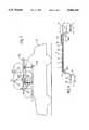
- FIGS. 5 and 6illustrate a support rack shown in FIG. 5 but installed above the roof of a vehicle
- FIG. 7illustrates a support rack according to a second embodiment of the invention in its home position and in its extended position above the roof of a vehicle;
- FIG. 8illustrates the support rack according to FIG. 7 on the roof of a vehicle seen from above;
- FIG. 9illustrates a longitudinal sectional view of a support bar of a support rack according to FIG. 7;
- FIG. 10illustrates a cross-sectional view of the device according to FIG. 7;
- FIG. 11illustrates a third embodiment of the invention
- FIG. 12illustrates a detail of FIG. 11
- FIG. 13illustrates a detail of a modification of a mechanism according to FIGS. 3 and 4;
- FIG. 13aillustrates a detail of the mechanism according to FIG. 13 seen from above.
- FIG. 14illustrates details of the latch mechanism.
- FIG. 1a vehicle 20 is illustrated which carries on its roof a roof rack 21 comprising a support bar 1 which is fastened to the roof of the vehicle 20 on its legs 8 with the aid of traditional fixation means.
- the support bar 1carries a bicycle 22 as well as a case 23 which are fixed on the bar 1 by a traditional fixation means such as currently used with known support bars.
- a user 24is illustrated on the side of the vehicle 20 in order to show that any manipulation for fixing bicycle 22 or case 23 or others, need to be effected traditionally above the roof of the vehicle in a manner which renders those manipulations rather difficult or even impossible for users of small size.
- Reference sign 25shows schematically the existence of a mechanism which permits to develop or to extend the support bar 1 such as to obtain a lateral extension and a lowering of a portion of support bar 1 in order to permit the user 24 to fasten the load on the extended and lowered support portion at a level which is more convenient.
- FIG. 2shows the same vehicle 20 with the support rack 21 according to FIG. 1 in its extended position and one understands easily the improvement of the conditions for the fastening of the load for user 24 after the positioning of mechanism 25 of bar 1 in its extended position.
- the mechanism of extensionwhich is generally indicated with reference sign 25 in FIG. 1, comprises a support portion 4 which, independently of the position of mechanism 25 remains always in a horizontally oriented position, as well as an intermediary portion 3 which connects the support portion 4 generally to the support bar 1.
- Bicycle 22 of FIG. 1 and storage case 23may thus be mounted on the support portion 4 during its extended and lowered position, and after fixation of the load on the support portion in positions 22b and 23b, the support portion 4 as well as the load which is supported thereon may be lifted above the roof of the car by a combined horizontal and vertical movement until it finally assumes a position such as indicated in FIG. 1, in which position mechanism 25 may be latched.
- FIG. 3is a longitudinal sectional view of support bar 1 mounted across the roof of a car 9, where it is supported by two legs 8.
- Support bar 1comprises a stationary tubular structure 11, at the interior of which there is arranged a mobile element which comprises essentially a slide 2, two parallel rods 3' and a bar 4 which serves as the port portion such as described in FIG. 2, whereas the two rods 3' correspond to the intermediary element 3 of FIG. 2.
- the tubular structure 11comprises at its upper surface a non-represented longitudinal opening which permits the passage of fixation elements, whereby this opening extends at least over a portion of the length of the tubular structure.
- the two parallel rods 3'are each fixed by one of their ends to slide 2 at two points of pivoting fixation, the other ends being fixed on the support portion 4 also at two points of pivoting fixation 13.
- the two points of pivoting fixation on each end of the parallel rods 3'are positioned each time one above the other, and are separated by an essentially identical distance, such as to permit to maintain the vertical superposition of the two fixation points 13 during the pivoting movement of the rods 3'.
- End 12 of the support portion 4which is remote from the end of the support portion 4 which is connected to the two rods, is provided with a handle 5 in order to permit extraction of the mobile element from the tubular structure of the support bar 1.
- Handle 5comprises a portion 7 including a not shown latch which permits latching handle 5 in the position such as illustrated in FIG. 3.
- a second handle 5'is arranged at the other side of the car roof and belongs to a second stationary element which is positioned in parallel and in symetric relationship behind the one shown.
- the mobile elementconsists essentially of slide 2, rods 3' as well as the support portion 4 and is disposed at the interior of the tubular structure 11 of support bar 1 such as to permit its actual extraction by applying a traction force onto handle 5.
- FIG. 4shows several positions of rods 3' and of support portion 4 after extraction of the entire mobile element and in various vertical positions.
- Slide 2may comprise rolls 1a in order to facilitate longitudinal movement thereof within the interior of the tubular structure 11.
- the mobile elementis indicated in a first upper position in dotted lines, which position represents the beginning of the lowering of the support portion 4, which lowering comes to an end in an intermediary position such as designated in full lines.
- Rods 3'may comprise telescopic portions 14 which permit further lowering of support portion 4 in order to assume a still lower position such as indicated again in dotted lines.
- support portion 4may also comprise telescopic portions 14a which permit extending the support portion 4 in order to create more space during the fixation of the load.
- Extension 7 of handle 5may serve as a cover for the leg 8 as well as support plate for a latch means which connects extension 7 to leg 8.
- FIG. 5illustrates a car 20 shown from above and one recognizes easily two pairs of support bars 1 whereof each pair comprises two bars which are oriented in inversed directions such as to permit the extension of mobile elements 3, 4 on either side of each pair of support bars 1.
- the pairs of support barsare mounted on the roof of the car at locations which are spaced from each other in a longitudinal direction of the car in order to define a fixed plane which permits the stabilization of the load at at least two points.
- FIG. 6illustrates details of the support bar according to FIG. 4 positioned on the roof of a car 20 and one may easily understand the advantages of the present invention which provides the possibility of fastening the load on the support portion 4 in a lowered position, either in a position such as illustrated in full lines or even further extended until the end of the extension of the telescopic mechanism 14. This clearly explains the advantages over a support rack such as illustrated in FIG. 1, and the necessary manipulations during the utilization of such traditional support racks.
- This limitationmay be incorporated by an abutment at any convenient location, or for instance by a lever which extends between the upper fixation point 13' of the slide and the lower fixation point 13 of the support portion 4, in order to limit the variation in the distance between these two fixation points.
- FIG. 7shows a support rack according to a different embodiment of the present invention on the roof of a car 20, whereby this embodiment is shown more clearly in FIG. 10, wherein the load and the phantom shape of the car have been omitted.
- FIG. 10one can see two pairs of support bars 1 whereof the mobile elements which comprise support portions 4 and intermediate portions 3 are indicated in two positions.
- the mobile element according to this embodiment of the inventionis constituted by a single piece in the form of a crank, the function of which will be described in detail with reference to FIGS. 9 and 11.
- Each crankcomprises a guide portion 2 positioned at the interior of support bar 1 and adapted such as to slide axially with respect to support bar 1 and which is further capable of executing a rotation about its own longitudinal axis.
- This guide portion 2is connected to support portion 4 by means of intermediate portion 3 and the three portions 2, 3 and 4 form an integral non-deformable member.
- This rotation of the mobile elementwhich has the form of a crank, may be permitted over 360° or only over a limited angle of essentially 90° or somewhat more for reasons as described further hereinbelow.
- the two support portions 4which are visible in the form of small circles of projection only, are connected with each other by a support rail 6.
- This railis in its lower position when the crank is orientated such that intermediate portion 3 is directed downwardly, and during the rotation of the crank about a quarter of a full circle, said rail 6 may be lifted to a position at the level of the support bars 1 or even beyond these support bars, if the rotation about a quarter of the circle is sufficiently extended to permit a passage of rail 6 beyond bar 1.
- This lifting of the rail above the support bar 1is of course executed while the support portion 4 is in its extended position in order to permit the passage of the rail on top of support bars 1.
- FIG. 8which shows the support rack according to this second embodiment of the present invention seen from above the car
- the dotted linesillustrate the lifted position of the crank which differs from the extended and the lowered position (in full lines) not only by a different vertical position of support portion 4 but also by a different position of horizontal extension.
- the support rack of FIG. 8comprises two support rails 6 at each side of the car, which support rails connect the two support portions 4 of the two mobile elements which are extensible from the same side of the car.
- the support rack according to the present inventioncomprises a single support bar and a support structure 11, the two crank 2, 3, 4 being introduced by opposite ends of the tubular structure.
- the left crank 2, 3, 4is illustrated in its lowered position in full lines, to other positions of extension by the telescopic portions 14 (for vertical extension) and 14' (for horizontal extension) being illustrated in dotted lines.
- the right crankis indicated in full lines in its home positions 2a, 3a, 4a and latched by latch member 7, and in three different extended positions, upper position 4" and lowered positions 4' and 4b.
- support bar 1may comprise a latch means 7' which permits immobilizing crank 2, 3, 4 in its upper position.
- This latch meansmay for instance comprise a member which is axially fixed on bar 1 but which may move in vertical direction in order to liberate or cover a longitudinal slot 15 in which intermediate portion 3 is slidingly received.
- the latch membermay comprise a vertical slot which crosses slot 15 of bar 1 and which maintains intermediate portion 3 at the point of intersection of the two slots.
- FIG. 14depicts latch 7' in more detail.
- telescopic portions 8may be provided on intermediary portion 4 as well as on support portions 4 in order to permit an ideal adjustment of the support portion 4 before the fixation of the load thereon.
- FIG. 11shows a third embodiment of the present invention which differs from the embodiment of the crank type only by the fact that the guiding portion consists of a cylinder 29 which is adapted to slide on a bar 30 which is arranged at the interior of the tubular portion of support bar 1.
- the movement of mobile element 29, 3, 4 of this embodimentis similar to the movement of the mobile element described with respect to FIGS. 8, 9 and 10, with the exception that the axial sliding of the guiding portion is not effected by a sliding of a bar within the interior of a tubular element but rather by the sliding of a tubular element on a fixed bar.
- This fixed bar 30may be held at its ends by the end walls of the tubular bar 1 as well as by a central leg 14 which may optionally be provided in order to increase the stability of the assembly.
- the tubular bar 1comprises longitudinal slots in order to permit the passage of the intermediary portion 3 during the translatory movement of the mobile element whereof one portion is located within the interior of the tubular bar 1 and another portion is located outside thereof.
- This longitudinal slotin particular in the case as illustrated in FIG. 11, may end in a more or less peripherally oriented slot 15 which serves as guide for the rotation of the mobile element.
- FIG. 12illustrates a detail of the assembly according to FIG. 11.
- FIG. 12represents a transverse sectional view along lines XII--XII of FIG. 11 and one can distinguish the tubular support member 11 having a rectangular profile, within which is located bar 30 which comprises over its longer portion also a rectangular cross section.
- Bar 30has a portion 13, corresponding to the location of cylindrical portion 29 of the mobile element in FIG. 11, in which portion 13 bar 30 comprises a circular cross section.
- the cylindrical portion 29 of the mobile elementcomprises at its interior a packing element 17 which provides an inner rectangular opening serving as guide for the sliding of the tubular portion 29 along bar 30 in a manner as to inhibit a possible rotation of the mobile element about bar 30 due to the positive engagement of the rectangular section of bar 30 in the interior of the packing element 17 of the cylindrical portion 29.
- the cylindrical portion 29is situated around portion 13 of circular cross-section such as to permit rotation of the mobile element about bar 30 in order to effectuate the lowering of the support portion 4 of the mobile element.
- FIG. 12there is also visible slot 15 of the tubular element 11, which slot serves to permit the intermediary portion 3 of the mobile element to traverse the side wall of element 11 in order to connect portion 29 which is located at the interior of the tubular bar with support portion 4 which is located outside thereof.
- FIG. 13depicts a detail of a modified embodiment similar to that of FIG. 3.
- the vertical dimension of the tubular section and the concerned components of the mobile elementare selected sufficiently large in order to permit to situate the two points of fixation of the two rods 3 onto the slide 2 in vertically spaced relationship
- This dispositionprovides the advantage that the stationary tubular structure 11, in particular in an embodiment where the mobile element slides within the interior of this stationary element, may be executed such as to avoid excessive height and to conform thereby to the typical dimensions of a traditional support rack.
- the type of fixation and the thickness of rods 3a as well as of the end portions of the support portion 4a and guide portion 2amay be such that the transversal cross section of the mobile element is practically constant over its entire length when the support portion 4a is in actual alignment with guide portion 2a.
- FIG. 13aillustrates this disposition
- FIG. 14shows the latch mechanism in more detail, whereby the stationary tubular element 11 has a hollow square cross-section including a longitudinal slot 15.
- Guide portion 2 of a crank 2, 3, 4is received within stationary tubular member 11 such as to be capable of sliding in both longitudinal directions as indicated by arrow A, whereby guiding portion 2 is held within the interior 11' of stationary tubular member 11 by any conveniently positioned bearings, which are not shown.
- Intermediary portion 3 of mobile element 2, 3, 4which has the shape of a crank, exits from the interior 11' of the tubular stationary member 11 through slot 15 in order to meet support portion 4 which is always located outside of tubular member 11, and during axial movement of guide member 2 within the tubular member 11 in accordance to arrow A, intermediary member 3 slides along slot 15.
- Latch member 7'which is illustrated in FIG. 14 in its latching position, may be lifted so that its vertical slot 7" completely liberates slot 15 of tubular member 11, such that crank 2, 3, 4 may freely slide along the entire length of its permetted stroke.
- Latch member 7'is connected with tubular member 11 by any conventional means (not shown) which permit to maintain latch member 7' in a axially fixed position with respect to the tubular member 11, however in a manner which permits partial lifting of latch member 7' in a direction perpendicular to the longitudinal extension of tubular member 11 so as to completely liberate slot 15 in order to permit unhindered sliding of intermediary member 3 within slot 15.
- latch member 7'is lowered in its position indicated in FIG. 14 while intermediary member 3 is in a position which is shown in FIG. 14, such as to immobilize intermediary portion 3 at the intersection of slots 5 and 7" which makes any further axial sliding of crank 2, 3, 4 within tubular member 11 impossible.
- Any conventional locking mechanismmay be provided in order to lock latch member 7' in its position as shown in FIG. 14.
- Slot 7"may have a tapered entry opening in order to faciliate operation of latch 7'.
- the sliding of the mobile elementdoes not imply axial movement of a member within a tubular structure, but outside of and along a non-covered guide bar, which may have the advantage to inhibit accumulation of humidity at inaccessible locations.
- bar 30has square cross-section along its entire length, whereby the side portions comprise a twist such as to guide a spiral rotation of the crank during its final part of extension.
- the support rails 6may be replaced by rails which are rigidly fixed on to the roof of the car, which may be envisaged in particular in case where the load itself is rigid and easy to fasten on the support portions 4, such as a long storage case.
- a means of mechanical assistance 32a/32b of this typemay be connected between the mobile portions of the mobile element in order to assist the lifting of the load to the level of the roof only, or it may also be connected to the stationary elements in order to assist the horizontal shifting of the lifted load to assume its correct transversal position above the roof of the car.
Landscapes
- Engineering & Computer Science (AREA)
- Mechanical Engineering (AREA)
- Fittings On The Vehicle Exterior For Carrying Loads, And Devices For Holding Or Mounting Articles (AREA)
Abstract
Description
Claims (23)
Applications Claiming Priority (4)
| Application Number | Priority Date | Filing Date | Title |
|---|---|---|---|
| CH141492 | 1992-05-04 | ||
| CH1414-92 | 1992-05-07 | ||
| CH1463-92 | 1992-05-07 | ||
| CH146392 | 1992-05-07 |
Publications (1)
| Publication Number | Publication Date |
|---|---|
| US5360150Atrue US5360150A (en) | 1994-11-01 |
Family
ID=25687581
Family Applications (1)
| Application Number | Title | Priority Date | Filing Date |
|---|---|---|---|
| US08/054,739Expired - LifetimeUS5360150A (en) | 1992-05-04 | 1993-04-29 | Roof rack for vehicles |
Country Status (5)
| Country | Link |
|---|---|
| US (1) | US5360150A (en) |
| EP (1) | EP0568855A1 (en) |
| JP (1) | JPH0624276A (en) |
| AU (1) | AU3712193A (en) |
| CA (1) | CA2095193A1 (en) |
Cited By (67)
| Publication number | Priority date | Publication date | Assignee | Title |
|---|---|---|---|---|
| US5569167A (en)* | 1995-03-28 | 1996-10-29 | Friedli; Faye E. | Rehabilitation apparatus in combination with a motor-driven vehicle |
| US5570825A (en)* | 1995-05-22 | 1996-11-05 | Cona; John A. | Rear mount bicycle carrier rack for motor vehicles |
| US5586702A (en)* | 1995-04-12 | 1996-12-24 | Sadler; William R. | Vehicle cargo carrier |
| US5662254A (en)* | 1995-08-16 | 1997-09-02 | Kar-Rite International | Rack for vehicles |
| US5673831A (en)* | 1996-08-14 | 1997-10-07 | Spratt; William L. | Tip down vehicle top carrier |
| US5690259A (en)* | 1996-05-02 | 1997-11-25 | Montani; John J. | Modular bicycle rack system |
| US5709521A (en)* | 1996-05-21 | 1998-01-20 | Glass; Dennis | Lift assist bicycle carrier for car rooftop |
| US5791857A (en)* | 1996-10-24 | 1998-08-11 | Theodore Ziaylek, Jr. | Automatic ladder lowering and storage device for use with an emergency vehicle |
| US5881937A (en)* | 1997-10-14 | 1999-03-16 | Sadler; William R. | Movable frame assembly |
| WO1999015742A1 (en)* | 1997-09-23 | 1999-04-01 | Rosen Products Llc | Stowable support apparatus |
| US5988470A (en)* | 1998-02-09 | 1999-11-23 | Siciliano; Paul | Quick release and car roof rack system |
| US6131781A (en)* | 1996-11-18 | 2000-10-17 | Industri Ab Thule | Equipment load assist to roof rack |
| US6152341A (en)* | 1998-08-28 | 2000-11-28 | Outdoor Innovations, Inc. | Vehicle hitch mounted cargo carrier |
| US6158638A (en)* | 1999-10-22 | 2000-12-12 | Szigeti; Josef | Vehicle roof rack |
| US6357643B1 (en)* | 1999-03-03 | 2002-03-19 | Daimlerchrysler Ag | Roof extension for a motor vehicle |
| US6428263B1 (en) | 2000-07-06 | 2002-08-06 | Thomas Schellens | Vehicular rooftop load elevating device |
| US6427889B1 (en)* | 2001-01-11 | 2002-08-06 | Avraham Y. Levi | Ladder rack for hi bay vans |
| US20020125280A1 (en)* | 2001-01-16 | 2002-09-12 | Allen Scott R. | Boat loading system for a vehicle |
| WO2002090150A1 (en) | 2000-05-06 | 2002-11-14 | Volk Daniel J | Device and method for loading cargo on a vehicle roof |
| US6561396B2 (en) | 2001-02-23 | 2003-05-13 | Johnson Outdoors Inc. | Automobile cargo carrier system |
| US6638000B2 (en)* | 2001-08-08 | 2003-10-28 | Ford Global Technologies, Llc | Bicycle lift for a vehicle roof rack |
| US20040028510A1 (en)* | 2002-03-06 | 2004-02-12 | Jones Bryon C. | Mechanically assisted vehicular roof rack |
| US20040124221A1 (en)* | 2002-09-12 | 2004-07-01 | Dr. Ing. H.C.F. Porsche Aktiengesellschaft | Roof rack for vehicles |
| US20040131455A1 (en)* | 2002-11-07 | 2004-07-08 | Henderson Jack V. | Side service storage apparatus |
| US6772928B2 (en)* | 2002-04-24 | 2004-08-10 | Ford Global Technologies, Llc | Multipurpose activity frame for use on articulating roof rack system |
| US20040238580A1 (en)* | 2003-06-02 | 2004-12-02 | Bruner Scott A. | Roof rack for recreational vehicle |
| US20050116002A1 (en)* | 2002-07-08 | 2005-06-02 | Thule Sweden Ab | Load carrier |
| US20060196904A1 (en)* | 2005-03-02 | 2006-09-07 | Timothy Tucker | Easy loading cargo rack assembly for vehicle |
| US20060280583A1 (en)* | 2004-09-27 | 2006-12-14 | Settelmayer Joseph J | Top rack with side load descent mechanism |
| US20060285954A1 (en)* | 2005-06-10 | 2006-12-21 | Neary Timothy E | Roof rack for vehicles |
| US7631916B1 (en) | 2008-01-09 | 2009-12-15 | Tracy Coleman | Tilting truck rack |
| US20100127031A1 (en)* | 2008-06-26 | 2010-05-27 | Yakima Products, Inc. | Coordinated adjustable trunk rack for carrying bicycles |
| US20110079621A1 (en)* | 2009-12-11 | 2011-04-07 | Wally Byers | Carrier racks for vehicles |
| US20110139838A1 (en)* | 2009-06-08 | 2011-06-16 | Yakima Products, Inc. | Boat rack |
| US7992682B2 (en) | 2007-12-21 | 2011-08-09 | Michael Paul Ziaylek | Ladder storing apparatus for use with an emergency vehicle |
| US8322580B1 (en) | 2010-07-12 | 2012-12-04 | Billy Hamilton | Retractable cargo carrying device |
| US20130008931A1 (en)* | 2011-07-05 | 2013-01-10 | Lopin Wang | Roof rack device |
| US8985933B2 (en) | 2012-06-05 | 2015-03-24 | Michael P. Ziaylek | Remote equipment storage apparatus with a downwardly extendable retrieval position |
| USD729142S1 (en) | 2013-05-10 | 2015-05-12 | Michael P. Ziaylek | Remote equipment storage apparatus for an emergency vehicle |
| EP2773533A4 (en)* | 2011-11-02 | 2015-06-17 | Paul Kevin Buller | ROOFING ROOF RACK WITH LOADING AND LOADING |
| USD739990S1 (en) | 2013-06-18 | 2015-09-29 | Yakima Products, Inc. | Boat carrier having two saddles |
| US9187047B2 (en) | 2012-04-30 | 2015-11-17 | Yakima Products, Inc. | Retention dock |
| US9371040B2 (en) | 2012-03-22 | 2016-06-21 | Joseph TOWNSEND | Pivoting roof rack |
| US9381866B2 (en) | 2009-06-15 | 2016-07-05 | Yakima Products, Inc. | Crossbar clamp devices |
| US20160207471A1 (en)* | 2015-01-21 | 2016-07-21 | Ranger Design | Ladder storing and releasing assembly |
| US9409527B2 (en) | 2007-09-21 | 2016-08-09 | Hubco Automotive Limited | Extendable roof rack |
| US9463748B2 (en) | 2013-09-09 | 2016-10-11 | Api Engineering, Llc | Powered cargo rack for tall vehicles |
| US20170028928A1 (en)* | 2015-07-31 | 2017-02-02 | Robert W Fifield | Rooftop Bike Rack System |
| USD779386S1 (en) | 2015-06-08 | 2017-02-21 | Yakima Products, Inc. | Hub for bicycle rack |
| USD780641S1 (en) | 2015-06-08 | 2017-03-07 | Yakima Products, Inc. | Frame for bicycle rack |
| US9815415B2 (en) | 2015-06-05 | 2017-11-14 | Yakima Products, Inc. | Adjustable bicycle carrier |
| US9827915B1 (en) | 2016-10-15 | 2017-11-28 | Ryan P. Chappell | Expandable cargo rack system |
| US9914400B1 (en)* | 2017-09-22 | 2018-03-13 | Ralph Johnsrud | Rooftop cargo loader |
| US10040402B1 (en) | 2017-02-28 | 2018-08-07 | Lawrence James Brusselback | Bike lifting cargo rack for vehicles |
| US10040403B2 (en) | 2015-06-09 | 2018-08-07 | Yakima Products, Inc. | Crossbar clamp actuator |
| US10246025B1 (en)* | 2015-07-21 | 2019-04-02 | University Of South Florida | Kayak loading system |
| US20190241127A1 (en)* | 2018-02-06 | 2019-08-08 | Todd J. Schweitzer | Roof rack system |
| US10507770B2 (en)* | 2015-07-09 | 2019-12-17 | Go Flat Rack Limited | Bicycle carriers |
| US10543771B2 (en) | 2016-06-05 | 2020-01-28 | Yakima Products, Inc. | Vehicle rooftop rack assembly |
| US10576903B2 (en) | 2016-06-05 | 2020-03-03 | Yakima Products, Inc. | Upright bike carrier |
| WO2020154401A1 (en)* | 2019-01-22 | 2020-07-30 | Sportslinq LLC | Rooftop mount for exercise equipment |
| US10766427B2 (en)* | 2018-06-06 | 2020-09-08 | Adrian Steel Company | Vehicle ladder rack assembly |
| US20220324390A1 (en)* | 2019-04-26 | 2022-10-13 | Inneva Group Limited | Vehicle rack system |
| US20230050631A1 (en)* | 2022-04-08 | 2023-02-16 | Ningbo Tuoluzhe Auto Accessories Co., Ltd. | Liftable luggage carrier on car roof |
| US11858468B2 (en) | 2018-06-01 | 2024-01-02 | 9358-3433 Quebec Inc. | Lift-assisted rack for a vehicle |
| US11945412B1 (en) | 2023-09-08 | 2024-04-02 | Lawrence James Brusselback | Bike lifting cargo rack for vehicles |
| US12054122B1 (en)* | 2024-03-19 | 2024-08-06 | Arthur Brad Cooper | Vehicle cargo transport system |
Families Citing this family (7)
| Publication number | Priority date | Publication date | Assignee | Title |
|---|---|---|---|---|
| DE4407510A1 (en)* | 1994-03-07 | 1995-09-14 | Hymer Leichtmetallbau | Bicycle rack for roof mounting on motor vehicles |
| EP0694440A1 (en)* | 1994-07-25 | 1996-01-31 | Milz Produkte AG | Roof rack |
| US5782391A (en)* | 1996-11-22 | 1998-07-21 | Cretcher; Gary S. | Vehicle roof rack loading mechanism |
| DE10157428B4 (en)* | 2001-11-25 | 2006-03-16 | Webasto Ag | Load bearing device for the roof of a vehicle |
| KR100831002B1 (en)* | 2007-05-25 | 2008-05-20 | 인제대학교 산학협력단 | Roof Carrier Feeder |
| NO342801B1 (en) | 2017-04-26 | 2018-08-06 | Hpg As | Lifting and lowering device, as well as load supporting system |
| FR3128923B1 (en)* | 2021-11-10 | 2023-10-27 | Univ Angers | Roof box for vehicle |
Citations (10)
| Publication number | Priority date | Publication date | Assignee | Title |
|---|---|---|---|---|
| US2551351A (en)* | 1947-06-06 | 1951-05-01 | Rose Swenson | Box and boat automobile carrier |
| US4003485A (en)* | 1975-07-17 | 1977-01-18 | Nelson Weeks Edgerton | Vehicle-top loader |
| US4350471A (en)* | 1979-10-16 | 1982-09-21 | Binz Gmbh & Co. | Roof rack in particular for cross country vehicles, ambulances and the like |
| EP0067723A1 (en)* | 1981-06-17 | 1982-12-22 | John Frederick Williams | Load support means for motor vehicles |
| GB2118501A (en)* | 1982-03-02 | 1983-11-02 | Ronic Staal Bv | Roof rack device |
| US4446998A (en)* | 1981-12-07 | 1984-05-08 | Taig Alistair G | Support assembly for a vehicle |
| JPS61146655A (en)* | 1984-12-21 | 1986-07-04 | Masahiro Orukawa | Sliding roof carrier |
| US4826387A (en)* | 1986-12-18 | 1989-05-02 | Marcel Audet | Vehicle roof rack |
| FR2673404A1 (en)* | 1991-02-28 | 1992-09-04 | Surirey Jagou | Device for transporting and handling long objects on the roof of a van |
| EP0511179A1 (en)* | 1991-04-24 | 1992-10-28 | GRUPPO MECCANICHE LUCIANI & C. - S.n.c. | Luggage-rack for cars having a high roof |
Family Cites Families (2)
| Publication number | Priority date | Publication date | Assignee | Title |
|---|---|---|---|---|
| GB2073686A (en)* | 1980-04-08 | 1981-10-21 | Golze R R | Vehicle rooftop carrier |
| DE4229762A1 (en)* | 1991-09-17 | 1993-03-18 | Volkswagen Ag | ROOF RACK WITH A LOADING AID |
- 1993
- 1993-04-20EPEP93106359Apatent/EP0568855A1/ennot_activeWithdrawn
- 1993-04-26AUAU37121/93Apatent/AU3712193A/ennot_activeAbandoned
- 1993-04-29CACA002095193Apatent/CA2095193A1/ennot_activeAbandoned
- 1993-04-29USUS08/054,739patent/US5360150A/ennot_activeExpired - Lifetime
- 1993-04-30JPJP5103373Apatent/JPH0624276A/enactivePending
Patent Citations (10)
| Publication number | Priority date | Publication date | Assignee | Title |
|---|---|---|---|---|
| US2551351A (en)* | 1947-06-06 | 1951-05-01 | Rose Swenson | Box and boat automobile carrier |
| US4003485A (en)* | 1975-07-17 | 1977-01-18 | Nelson Weeks Edgerton | Vehicle-top loader |
| US4350471A (en)* | 1979-10-16 | 1982-09-21 | Binz Gmbh & Co. | Roof rack in particular for cross country vehicles, ambulances and the like |
| EP0067723A1 (en)* | 1981-06-17 | 1982-12-22 | John Frederick Williams | Load support means for motor vehicles |
| US4446998A (en)* | 1981-12-07 | 1984-05-08 | Taig Alistair G | Support assembly for a vehicle |
| GB2118501A (en)* | 1982-03-02 | 1983-11-02 | Ronic Staal Bv | Roof rack device |
| JPS61146655A (en)* | 1984-12-21 | 1986-07-04 | Masahiro Orukawa | Sliding roof carrier |
| US4826387A (en)* | 1986-12-18 | 1989-05-02 | Marcel Audet | Vehicle roof rack |
| FR2673404A1 (en)* | 1991-02-28 | 1992-09-04 | Surirey Jagou | Device for transporting and handling long objects on the roof of a van |
| EP0511179A1 (en)* | 1991-04-24 | 1992-10-28 | GRUPPO MECCANICHE LUCIANI & C. - S.n.c. | Luggage-rack for cars having a high roof |
Cited By (93)
| Publication number | Priority date | Publication date | Assignee | Title |
|---|---|---|---|---|
| US5569167A (en)* | 1995-03-28 | 1996-10-29 | Friedli; Faye E. | Rehabilitation apparatus in combination with a motor-driven vehicle |
| US5586702A (en)* | 1995-04-12 | 1996-12-24 | Sadler; William R. | Vehicle cargo carrier |
| US5570825A (en)* | 1995-05-22 | 1996-11-05 | Cona; John A. | Rear mount bicycle carrier rack for motor vehicles |
| US5662254A (en)* | 1995-08-16 | 1997-09-02 | Kar-Rite International | Rack for vehicles |
| US5690259A (en)* | 1996-05-02 | 1997-11-25 | Montani; John J. | Modular bicycle rack system |
| US5709521A (en)* | 1996-05-21 | 1998-01-20 | Glass; Dennis | Lift assist bicycle carrier for car rooftop |
| US5673831A (en)* | 1996-08-14 | 1997-10-07 | Spratt; William L. | Tip down vehicle top carrier |
| US5791857A (en)* | 1996-10-24 | 1998-08-11 | Theodore Ziaylek, Jr. | Automatic ladder lowering and storage device for use with an emergency vehicle |
| US6131781A (en)* | 1996-11-18 | 2000-10-17 | Industri Ab Thule | Equipment load assist to roof rack |
| US6007036A (en)* | 1997-09-23 | 1999-12-28 | Rosen Products Llc | Stowable support apparatus |
| WO1999015742A1 (en)* | 1997-09-23 | 1999-04-01 | Rosen Products Llc | Stowable support apparatus |
| US5881937A (en)* | 1997-10-14 | 1999-03-16 | Sadler; William R. | Movable frame assembly |
| US5988470A (en)* | 1998-02-09 | 1999-11-23 | Siciliano; Paul | Quick release and car roof rack system |
| US6152341A (en)* | 1998-08-28 | 2000-11-28 | Outdoor Innovations, Inc. | Vehicle hitch mounted cargo carrier |
| US6293451B1 (en) | 1998-08-28 | 2001-09-25 | Outdoor Innovations, Inc. | Vehicle hitch mounted cargo carrier |
| US6357643B1 (en)* | 1999-03-03 | 2002-03-19 | Daimlerchrysler Ag | Roof extension for a motor vehicle |
| US6158638A (en)* | 1999-10-22 | 2000-12-12 | Szigeti; Josef | Vehicle roof rack |
| WO2002090150A1 (en) | 2000-05-06 | 2002-11-14 | Volk Daniel J | Device and method for loading cargo on a vehicle roof |
| US6428263B1 (en) | 2000-07-06 | 2002-08-06 | Thomas Schellens | Vehicular rooftop load elevating device |
| US6427889B1 (en)* | 2001-01-11 | 2002-08-06 | Avraham Y. Levi | Ladder rack for hi bay vans |
| US20020125280A1 (en)* | 2001-01-16 | 2002-09-12 | Allen Scott R. | Boat loading system for a vehicle |
| US7036698B2 (en)* | 2001-01-16 | 2006-05-02 | Yakima Products, Inc. | Boat loading system for a vehicle |
| US6561396B2 (en) | 2001-02-23 | 2003-05-13 | Johnson Outdoors Inc. | Automobile cargo carrier system |
| US6638000B2 (en)* | 2001-08-08 | 2003-10-28 | Ford Global Technologies, Llc | Bicycle lift for a vehicle roof rack |
| US20040028510A1 (en)* | 2002-03-06 | 2004-02-12 | Jones Bryon C. | Mechanically assisted vehicular roof rack |
| US6772928B2 (en)* | 2002-04-24 | 2004-08-10 | Ford Global Technologies, Llc | Multipurpose activity frame for use on articulating roof rack system |
| US20050116002A1 (en)* | 2002-07-08 | 2005-06-02 | Thule Sweden Ab | Load carrier |
| US20040124221A1 (en)* | 2002-09-12 | 2004-07-01 | Dr. Ing. H.C.F. Porsche Aktiengesellschaft | Roof rack for vehicles |
| US7108162B2 (en)* | 2002-09-12 | 2006-09-19 | Dr. Ing. H.C.F. Porsche Ag | Roof rack for vehicles |
| US20040131455A1 (en)* | 2002-11-07 | 2004-07-08 | Henderson Jack V. | Side service storage apparatus |
| US7048490B2 (en) | 2002-11-07 | 2006-05-23 | Decoma International Inc. | Side service storage apparatus |
| US7044346B2 (en) | 2003-06-02 | 2006-05-16 | Gulf Stream Coach, Inc. | Roof rack for recreational vehicle |
| US20040238580A1 (en)* | 2003-06-02 | 2004-12-02 | Bruner Scott A. | Roof rack for recreational vehicle |
| US20060280583A1 (en)* | 2004-09-27 | 2006-12-14 | Settelmayer Joseph J | Top rack with side load descent mechanism |
| US7780050B2 (en)* | 2005-03-02 | 2010-08-24 | Timothy Tucker | Easy loading cargo rack assembly for vehicle |
| US20060196904A1 (en)* | 2005-03-02 | 2006-09-07 | Timothy Tucker | Easy loading cargo rack assembly for vehicle |
| US20060285954A1 (en)* | 2005-06-10 | 2006-12-21 | Neary Timothy E | Roof rack for vehicles |
| US9409527B2 (en) | 2007-09-21 | 2016-08-09 | Hubco Automotive Limited | Extendable roof rack |
| US7992682B2 (en) | 2007-12-21 | 2011-08-09 | Michael Paul Ziaylek | Ladder storing apparatus for use with an emergency vehicle |
| US7631916B1 (en) | 2008-01-09 | 2009-12-15 | Tracy Coleman | Tilting truck rack |
| US20100127031A1 (en)* | 2008-06-26 | 2010-05-27 | Yakima Products, Inc. | Coordinated adjustable trunk rack for carrying bicycles |
| US20110139838A1 (en)* | 2009-06-08 | 2011-06-16 | Yakima Products, Inc. | Boat rack |
| US8556146B2 (en) | 2009-06-08 | 2013-10-15 | Yakima Innovation Development Corporation | Boat rack |
| US10583784B2 (en) | 2009-06-15 | 2020-03-10 | Yakima Products, Inc. | Crossbar clamp devices |
| US9381866B2 (en) | 2009-06-15 | 2016-07-05 | Yakima Products, Inc. | Crossbar clamp devices |
| US10150423B2 (en) | 2009-06-15 | 2018-12-11 | Yakima Products, Inc. | Crossbar clamp devices |
| US20110079621A1 (en)* | 2009-12-11 | 2011-04-07 | Wally Byers | Carrier racks for vehicles |
| US8616424B2 (en) | 2009-12-11 | 2013-12-31 | Wally Byers | Carrier racks for vehicles |
| US8322580B1 (en) | 2010-07-12 | 2012-12-04 | Billy Hamilton | Retractable cargo carrying device |
| US8646667B2 (en)* | 2011-07-05 | 2014-02-11 | Beto Engineering and Marketing Co., Ltd. | Roof rack device |
| US20130008931A1 (en)* | 2011-07-05 | 2013-01-10 | Lopin Wang | Roof rack device |
| US9290130B2 (en) | 2011-11-02 | 2016-03-22 | Paul Kevin Buller | Load and lift roof rack |
| EP2773533A4 (en)* | 2011-11-02 | 2015-06-17 | Paul Kevin Buller | ROOFING ROOF RACK WITH LOADING AND LOADING |
| US9371040B2 (en) | 2012-03-22 | 2016-06-21 | Joseph TOWNSEND | Pivoting roof rack |
| US9187047B2 (en) | 2012-04-30 | 2015-11-17 | Yakima Products, Inc. | Retention dock |
| US8985933B2 (en) | 2012-06-05 | 2015-03-24 | Michael P. Ziaylek | Remote equipment storage apparatus with a downwardly extendable retrieval position |
| USD729142S1 (en) | 2013-05-10 | 2015-05-12 | Michael P. Ziaylek | Remote equipment storage apparatus for an emergency vehicle |
| USD739990S1 (en) | 2013-06-18 | 2015-09-29 | Yakima Products, Inc. | Boat carrier having two saddles |
| US9463748B2 (en) | 2013-09-09 | 2016-10-11 | Api Engineering, Llc | Powered cargo rack for tall vehicles |
| US9987995B2 (en)* | 2015-01-21 | 2018-06-05 | Ranger Design | Ladder storing and releasing assembly |
| US20160207471A1 (en)* | 2015-01-21 | 2016-07-21 | Ranger Design | Ladder storing and releasing assembly |
| US9815415B2 (en) | 2015-06-05 | 2017-11-14 | Yakima Products, Inc. | Adjustable bicycle carrier |
| USD780641S1 (en) | 2015-06-08 | 2017-03-07 | Yakima Products, Inc. | Frame for bicycle rack |
| USD779386S1 (en) | 2015-06-08 | 2017-02-21 | Yakima Products, Inc. | Hub for bicycle rack |
| US10391948B2 (en) | 2015-06-09 | 2019-08-27 | Yakima Products, Inc. | Selectable pitch crossbar-to-vehicle coupler |
| US10232791B2 (en) | 2015-06-09 | 2019-03-19 | Yakima Products, Inc. | Crossbar-to-vehicle coupler |
| US10040403B2 (en) | 2015-06-09 | 2018-08-07 | Yakima Products, Inc. | Crossbar clamp actuator |
| US10071693B2 (en) | 2015-06-09 | 2018-09-11 | Yakima Products, Inc. | Rooftop cargo carrying system |
| US10131288B2 (en) | 2015-06-09 | 2018-11-20 | Yakima Products, Inc. | Strap-type vehicle-to-crossbar coupler assembly |
| US10160394B2 (en) | 2015-06-09 | 2018-12-25 | Yakima Products, Inc. | Rooftop cargo carrying systems with biaxial clip adjustment |
| US10202083B2 (en) | 2015-06-09 | 2019-02-12 | Yakima Products, Inc. | Crossbar-to-vehicle coupler having adjustable toe angle |
| US10507770B2 (en)* | 2015-07-09 | 2019-12-17 | Go Flat Rack Limited | Bicycle carriers |
| US10246025B1 (en)* | 2015-07-21 | 2019-04-02 | University Of South Florida | Kayak loading system |
| US9987994B2 (en)* | 2015-07-31 | 2018-06-05 | Robert W Fifield | Rooftop bike rack system |
| US20170028928A1 (en)* | 2015-07-31 | 2017-02-02 | Robert W Fifield | Rooftop Bike Rack System |
| US10543771B2 (en) | 2016-06-05 | 2020-01-28 | Yakima Products, Inc. | Vehicle rooftop rack assembly |
| US10576903B2 (en) | 2016-06-05 | 2020-03-03 | Yakima Products, Inc. | Upright bike carrier |
| US9827915B1 (en) | 2016-10-15 | 2017-11-28 | Ryan P. Chappell | Expandable cargo rack system |
| US10040402B1 (en) | 2017-02-28 | 2018-08-07 | Lawrence James Brusselback | Bike lifting cargo rack for vehicles |
| US9914400B1 (en)* | 2017-09-22 | 2018-03-13 | Ralph Johnsrud | Rooftop cargo loader |
| US20190241127A1 (en)* | 2018-02-06 | 2019-08-08 | Todd J. Schweitzer | Roof rack system |
| US10668865B2 (en)* | 2018-02-06 | 2020-06-02 | Talem Capital, Llc | Roof rack system |
| US11325538B2 (en)* | 2018-02-06 | 2022-05-10 | Talem Capital, Llc | Roof rack system |
| US11919484B2 (en) | 2018-02-06 | 2024-03-05 | Talem Capital, Llc | Roof rack system |
| US11858468B2 (en) | 2018-06-01 | 2024-01-02 | 9358-3433 Quebec Inc. | Lift-assisted rack for a vehicle |
| US10766427B2 (en)* | 2018-06-06 | 2020-09-08 | Adrian Steel Company | Vehicle ladder rack assembly |
| WO2020154401A1 (en)* | 2019-01-22 | 2020-07-30 | Sportslinq LLC | Rooftop mount for exercise equipment |
| US11471724B2 (en) | 2019-01-22 | 2022-10-18 | Sportslinq LLC | Rooftop mount for exercise equipment |
| US20220324390A1 (en)* | 2019-04-26 | 2022-10-13 | Inneva Group Limited | Vehicle rack system |
| US20230050631A1 (en)* | 2022-04-08 | 2023-02-16 | Ningbo Tuoluzhe Auto Accessories Co., Ltd. | Liftable luggage carrier on car roof |
| US12134372B2 (en)* | 2022-04-08 | 2024-11-05 | Ningbo Tuoluzhe Auto Accessories Co., Ltd. | Liftable luggage carrier on car roof |
| US11945412B1 (en) | 2023-09-08 | 2024-04-02 | Lawrence James Brusselback | Bike lifting cargo rack for vehicles |
| US12054122B1 (en)* | 2024-03-19 | 2024-08-06 | Arthur Brad Cooper | Vehicle cargo transport system |
Also Published As
| Publication number | Publication date |
|---|---|
| AU3712193A (en) | 1993-11-11 |
| CA2095193A1 (en) | 1993-11-05 |
| EP0568855A1 (en) | 1993-11-10 |
| JPH0624276A (en) | 1994-02-01 |
Similar Documents
| Publication | Publication Date | Title |
|---|---|---|
| US5360150A (en) | Roof rack for vehicles | |
| US5121959A (en) | Slide mount for pick-up truck toolboxes | |
| US6006810A (en) | Awning support for mounting to a curved wall | |
| US4795067A (en) | Umbrella storage device | |
| US7441679B1 (en) | One sided adjustable cross rail | |
| EP0091889B1 (en) | A luggage carrier for vehicles | |
| EP0753637B1 (en) | Structure for the assembly of sliding doors | |
| US4167284A (en) | Collapsible campers | |
| JP2001017484A (en) | Side bed for attachment to bed | |
| KR102389801B1 (en) | Folding cover apparatus of vehicle cargo box | |
| JPH0455197Y2 (en) | ||
| RU2281218C1 (en) | Folding ladder for railway car compartment (versions) | |
| JPH0316385Y2 (en) | ||
| JPS59213864A (en) | Gate door mechanism | |
| KR102249110B1 (en) | Apparatus rainwater cover for vehicle | |
| JPS6135668Y2 (en) | ||
| JPS6336160Y2 (en) | ||
| JP4040489B2 (en) | Telescopic gate mounting structure | |
| KR0178937B1 (en) | Slide door of automobile | |
| KR930005512Y1 (en) | Umbrella stand for vehicle | |
| JP3369078B2 (en) | Carport | |
| RU92003401A (en) | MECHANIZED GARAGE | |
| JPS624160Y2 (en) | ||
| JPH0247076Y2 (en) | ||
| JPH0450737Y2 (en) |
Legal Events
| Date | Code | Title | Description |
|---|---|---|---|
| STPP | Information on status: patent application and granting procedure in general | Free format text:APPLICATION UNDERGOING PREEXAM PROCESSING | |
| AS | Assignment | Owner name:TOP TECHNOLOGIES INC., CANADA Free format text:ASSIGNMENT OF ASSIGNORS INTEREST;ASSIGNOR:PRAZ, JEAN-LUC;REEL/FRAME:008677/0823 Effective date:19970909 | |
| FPAY | Fee payment | Year of fee payment:4 | |
| AS | Assignment | Owner name:WESSA, SCOTT, WASHINGTON Free format text:ASSIGNMENT OF ASSIGNORS INTEREST;ASSIGNOR:TOP TECHNOLOGIES, INC.;REEL/FRAME:010676/0752 Effective date:19990730 Owner name:WESSA, KIM, WASHINGTON Free format text:ASSIGNMENT OF ASSIGNORS INTEREST;ASSIGNOR:TOP TECHNOLOGIES, INC.;REEL/FRAME:010676/0752 Effective date:19990730 | |
| FPAY | Fee payment | Year of fee payment:8 | |
| FEPP | Fee payment procedure | Free format text:PAT HOLDER NO LONGER CLAIMS SMALL ENTITY STATUS, ENTITY STATUS SET TO UNDISCOUNTED (ORIGINAL EVENT CODE: STOL); ENTITY STATUS OF PATENT OWNER: LARGE ENTITY | |
| REMI | Maintenance fee reminder mailed | ||
| FPAY | Fee payment | Year of fee payment:12 | |
| SULP | Surcharge for late payment | Year of fee payment:11 | |
| AS | Assignment | Owner name:WATERMARK PADDLESPORTS, INC., OREGON Free format text:ASSIGNMENT OF ASSIGNORS INTEREST;ASSIGNORS:WESSA, SCOTT;WESSA, KIM;REEL/FRAME:018923/0173 Effective date:20040813 Owner name:YAKIMA PRODUCTS, INC., OREGON Free format text:CHANGE OF NAME;ASSIGNOR:WATERMARK PADDLESPORTS, INC.;REEL/FRAME:018942/0308 Effective date:20050622 |