US5359893A - Multi-axes gyroscope - Google Patents
Multi-axes gyroscopeDownload PDFInfo
- Publication number
- US5359893A US5359893AUS07/810,062US81006291AUS5359893AUS 5359893 AUS5359893 AUS 5359893AUS 81006291 AUS81006291 AUS 81006291AUS 5359893 AUS5359893 AUS 5359893A
- Authority
- US
- United States
- Prior art keywords
- mass
- axis
- frame
- axes
- post
- Prior art date
- Legal status (The legal status is an assumption and is not a legal conclusion. Google has not performed a legal analysis and makes no representation as to the accuracy of the status listed.)
- Expired - Lifetime
Links
- 239000003990capacitorSubstances0.000claimsabstractdescription49
- 239000000758substrateSubstances0.000claimsdescription11
- 230000001133accelerationEffects0.000claimsdescription6
- 239000000463materialSubstances0.000claimsdescription3
- 230000035945sensitivityEffects0.000description8
- 238000000034methodMethods0.000description6
- 239000004065semiconductorSubstances0.000description4
- 238000010276constructionMethods0.000description3
- 238000005459micromachiningMethods0.000description3
- 238000010586diagramMethods0.000description2
- 230000000694effectsEffects0.000description2
- 238000004519manufacturing processMethods0.000description2
- 238000012986modificationMethods0.000description2
- 230000004048modificationEffects0.000description2
- 230000009471actionEffects0.000description1
- 238000013459approachMethods0.000description1
- 239000004020conductorSubstances0.000description1
- 239000013078crystalSubstances0.000description1
- 238000000151depositionMethods0.000description1
- PCHJSUWPFVWCPO-UHFFFAOYSA-NgoldChemical compound[Au]PCHJSUWPFVWCPO-UHFFFAOYSA-N0.000description1
- 239000010931goldSubstances0.000description1
- 229910052737goldInorganic materials0.000description1
- 238000005259measurementMethods0.000description1
- 239000002184metalSubstances0.000description1
- 229910052751metalInorganic materials0.000description1
- 230000007935neutral effectEffects0.000description1
- 229910021420polycrystalline siliconInorganic materials0.000description1
- 229920005591polysiliconPolymers0.000description1
- 238000012545processingMethods0.000description1
- 238000005070samplingMethods0.000description1
- 238000000926separation methodMethods0.000description1
- 229910052710siliconInorganic materials0.000description1
- 239000010703siliconSubstances0.000description1
- 239000000725suspensionSubstances0.000description1
- 230000001360synchronised effectEffects0.000description1
- 230000001960triggered effectEffects0.000description1
Images


Classifications
- G—PHYSICS
- G01—MEASURING; TESTING
- G01C—MEASURING DISTANCES, LEVELS OR BEARINGS; SURVEYING; NAVIGATION; GYROSCOPIC INSTRUMENTS; PHOTOGRAMMETRY OR VIDEOGRAMMETRY
- G01C19/00—Gyroscopes; Turn-sensitive devices using vibrating masses; Turn-sensitive devices without moving masses; Measuring angular rate using gyroscopic effects
- G01C19/56—Turn-sensitive devices using vibrating masses, e.g. vibratory angular rate sensors based on Coriolis forces
- G01C19/5719—Turn-sensitive devices using vibrating masses, e.g. vibratory angular rate sensors based on Coriolis forces using planar vibrating masses driven in a translation vibration along an axis
Definitions
- the present inventionpertains to micromechanical gyroscopes and more specifically to multi-directional micromechanical gyroscopes.
- gyroscopes and gyroscopic deviceswere constructed of relatively large and expensive electromagnetic devices. These electromagnetic devices incorporated coils and position sensors mounted for relatively high speed, continuous rotational movement.
- micromechanical rate gyroswere developed which included components formed by semiconductor processing techniques. While these devices are relatively small and utilize vibrational motion rather than continuous rotary motion, they are relatively insensitive and costly to manufacture.
- the micromechanical rate gyrosare constructed with a central mass, which because of the size of the gyro is very small and requires some very heavy material such as gold to provide sufficient mass.
- the central massis mounted in a gimbal structure including mutually orthogonal flexible axes, with the mass and gimbal structure generally lying in a common plane.
- the central mass and inner mounting gimbalare oscillated or vibrated about a first of the orthogonal axes and rotational movement about an axis perpendicular to the common plane produces vibrational movement about the other of the orthogonal axes, due to the Coriolis, or gyroscopic, effect.
- the described micromechanical rate gyrohas several problems. Specifically, the centrally mounted mass is expensive and difficult to manufacture. It is difficult to achieve a large enough mass to provide sufficient inertia for good sensitivity and this construction reduces sensing capacitor sensitivity. Also, if the mass is offset even slightly within the gimballed mounting a noticeable sensitivity to cross-axis acceleration is produced. Second, the amount of vibrational movement is limited by the fact that the planar constructed gimbal system is mounted adjacent to a planar surface and increasing the distance between the gimbal system and the planar surface substantially increases the size of the device, which reduces sensitivity due to increased capacitor spacing as well as increasing the cost and complexity of construction.
- the deviceis limited to a single axis device. Since the device only senses movement about a single axis, three of the devices must be mounted with the input axes in a mutually orthogonal relationship to sense movement in all directions.
- rate gyrosTo further reduce the size, cost and usefulness Of rate gyros, there is a need for micromechanical rate gyros with increased sensitivity, due to increased inertia achieved by an increased distance of movement and/or an increase in effective mass, higher vibration frequency and smaller capacitive plate separation. Further, it would be convenient to sense movement about more than one axis with a single device.
- a multi-axes vibration monolithic gyroscopeformed on a semiconductor substrate and including a mass mounted for vibrational movement parallel to the substrate and sensing apparatus positioned adjacent the mass for sensing forces produced by rotational movement on the mass about two orthogonal axes.
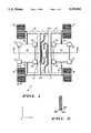
- FIG.1is a view in top plan of a multi-axes vibrational gyroscope embodying the present invention
- FIG. 2is a sectional view as seen from the line 2--2 in FIG. 1;
- FIG. 3is a sectional view as seen from the line 3--3 in FIG. 1;
- FIG.4is a sectional/schematic illustration of a portion of the gyroscope of FIG. 1;
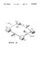
- FIG. 5is an enlarged view in perspective of a portion of FIG. 1;
- FIG. 6is a schematic diagram of a sensing and control circuit electrically attached to the gyroscope of FIG. 1;
- FIG. 7illustrates waveforms available at various points of the sensing and control circuit of FIG. 6;
- FIG. 8is a time-function chart illustrating the relationship between time and the various control functions of the sensing and control circuit of FIG. 6;
- FIG. 9is a view in top plan, similar to FIG. 1, of another embodiment.
- FIG. 10is a view in top plan, similar to FIG. 1, of yet another embodiment.
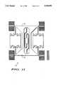
- FIG. 11is a view in top plan similar to FIG. 1 of another embodiment of a vibrational gyroscope.
- Gyroscope 10includes a mass 12 with a generally H shaped frame 14 having a central opening 13 through the middle cross-arm of the frame.
- a centrally located mounting post 15is affixed to a planar surface of a substrate so as to be perpendicular thereto.
- Post 15defines the Z axis of gyroscope 10.
- Frame 14is moveably attached to post 15 by means of a plurality, in this specific embodiment two, of helical springs 17A and 17B.
- Each of the helical springs 17A and 17Bare fixedly attached to post 15 at one end and to the inner edge of opening 13 of frame 14 at the other end.
- Helical springs 17A and 17Bare designed to maintain frame 14 in a plane parallel to the planar surface of the substrate while allowing limited vibrational movement in all directions.
- Mass 12further includes a pair of generally rectangularly shaped mass elements 22 and 23 mounted in the openings between the parallel arms of H shaped frame ].4. Each mass element 22 and 23 is affixed to the parallel arms of frame 14 by means of elongated resilient members 25 one each extending from the end of an arm to opposed sides; of mass elements 22 and 23. Resilient members 25 mount mass elements 22 and 23 for vibrational movement, independent of frame 14, along an X axis extending through each of the mass elements 22 and 23 and through the end of mounting post 15, perpendicular to the Z axis.
- a Y axisis further defined by mass 12 and extends in the plane of mass 12, through the end of post 15, mutually perpendicular to the X and Z axes.
- each plurality of driving elements 26, 27, 28 and 29each include upper and lower parallel, spaced apart rectangular conducting plates.
- each plurality of driving elements 26, 27, 28 and 29includes a pair of driving elements with the pair of driving elements 27 being positioned adjacent the left-hand corners of mass element 22 in FIG. 1, the pair of driving elements 28 being positioned adjacent the right-hand corners of mass element 22, the pair of driving elements 26 being positioned adjacent the left-hand corners of mass element 23 and the pair of driving elements 29 being positioned adjacent the right-hand corners of mass element 23.
- the pair of conducting plates of each of the driving elements of the pluralities of driving elements 26, 27, 28 and 29are positioned above and below (in FIGS. 1 and 5) the corners of mass elements 22 and 23. All of the conducting plates of the driving elements 26, 27, 28 and 29 are also parallel to mass 12.
- the plates 26are electrically connected, as are plates 27, 28 and 29.
- FIG. 5is an enlarged view in perspective illustrating in more detail mass element 12 and driving elements 27 and 28.
- the electrostatic attraction between plates 27, 28 and mass element 22, and similarly between plates 29, 26 and mass element 23,produces vibrational movement along the X axis of mass elements 22 and 23 independent of frame 14.
- the driving elementsare diametrically opposed and positioned to produce uniform vibrational movement of mass elements 22 and 23 in opposite directions, with synchronized driving pulses which results in zero force on frame 14, generally as experienced in a tuning fork.
- Sensing apparatuswhich includes sensing capacitors 30, 40, 41 and 42, one each, mounted at the end of each arm of frame 14, is designed to sense rotation of gyroscope 10 and frame 14 about the Y and Z axes.
- Each sensing capacitor 30, 40, 41 and 42includes a set of fixedly mounted upper plates, a set of fixedly mounted lower plates and a set of central plates attached to the end of frame 14 for movement therewith.
- sensing capacitor 30includes upper plates 30A and 30D, lower plates 30B and 30E and central plates 30C, as illustrated in more detail in FIGS. 3 and 4, with each of the other sensing capacitors 40, 41 and 42 being similarly designated.
- all of the capacitor platesare formed in the shape of elongated fingers extending in parallel spaced apart relationship.
- each sensing capacitor 30is divided into two sets of capacitors each set including fourteen upper plates 30A, 30D (six shown), fourteen lower plates 30B, 30E (six shown) and seven center plates 30C, (three shown), one set of which is illustrated in FIG. 4.
- the operation of gyroscope 10can be seen most easily by referring to the set of capacitor plates illustrated in FIG. 4 for example.
- the second, fourth, sixth, etc. upper plates 30Aare connected together and by means of an inverter 32 to a terminal 33.
- the first, third, fifth, etc. upper plates 30Dare connected together and by means of an inverter 34 to a terminal 35.
- the first, third, fifth, etc. lower plates 30Eare connected together and by means of an inverter 36 to a terminal 37.
- the second, fourth, sixth, etc. lower plates 30Bare connected together and by means of an inverter 38 to a terminal 39.
- the electrostatic forces between plates 30A-30E and 30Ccan be used in a manner to maintain plates 30C approximately centered between plates 30A-30E, gyroscope 10 remains in the most sensitive mode and the amount of drive required to center the capacitor plates is measured to determine the amount and direction of the rotationally induced forces acting on gyroscope 10.
- FIG. 6illustrates a schematic diagram of a sensing and control circuit electrically attached to gyroscope 10 of FIG. 1.
- FIG. 7illustrates waveforms available at various points in the sensing and control circuit.
- FIG. 8is a time-function chart illustrating the relationship between time and the various control functions of the sensing and control circuit of FIG. 6 over a limited time span.
- Central post 15, frame 14, mass elements 22 and 23 and the center plates 30C, 40C, 41C and 42C of sensing capacitors 36, 40, 41 and 42are all electrically connected and designated node 215 in FIG. 6.
- Sensing and control signalsare applied to the capacitor plates 30A-E, 40A-E, 41A-E and 42A-E via the logic components illustrated.
- an input terminal 1P1goes high forcing ground potential on capacitor plates 30B and 30E and V REF on capacitor plates 30A and 30D.
- an input terminal 1P2is driven low and an input terminal 1P3 is driven high to allow signals from a first latch 219 to control the drive voltages on capacitor plates 30A, 30B, 30D and 30E.
- Center plates 30Care held at VREF by a virtual ground amplifier 216.
- Amplifier 216has unity gain due to a switch 217 being closed by a low signal on an input terminal P4.
- input terminal P4is driven high and switch 217 is turned off so that amplifier 216 becomes active as a virtual ground integrating amplifier.
- input terminal 1P2is switched from low to high, which forces the voltage on capacitor plates 30B and 30E to switch from ground to V REF and capacitor plates 30A and 30D to switch from V REF to ground. Any difference in the capacitances formed by capacitor plates 30B, 30E and 30C versus 30A, 30D and 30C will result in a charge on node 215, which is amplified. inverted and converted into a voltage by amplifier 216. The signal from amplifier 216 is further amplified by an amplifier 218.
- latch 2119is a negative edge, triggered latch circuit clocked by the signal 1P2.
- latch 219a positive voltage from amplifier 218 is latched as a high and a negative voltage is latched as a low.
- the output signal from latch 219is fed back via inverter 227 and logic gates 229 thru 234 to inverters 235, 236, 36, 32, 38 and 34, which apply V REF and ground to capacitor plates 30D & 30A and & 30E.
- latch circuits 219 through 226are sampled and the average high and low driving periods are compared over extended time periods. For example, by comparing:
- Gyroscope 10is conveniently manufactured as a micromechanical structure on a semiconductor substrate by well known micromachining techniques including the use of sacrificial layers of etchable material and the growing and/or depositing of semiconductor/conductor layers such as polysilicon, doped silicon, metal, etc. Gyroscope 10 may also be conveniently manufactured by using bulk micromachining and wafer bonding techniques. Whatever technique is utilized, the lower sensing capacitor plates and the lower plates of driving elements 26, 27, 28 and 29 are formed in a first layer supported on the substrate. Post 15, mass 12 and the central capacitor plates are formed in a second layer spaced from the first layer. Post 15 is of course fixedly supported by the substrate.
- the upper capacitor plates and the upper plates of driving elements 26, 27, 28 and 29are formed in a third layer spaced from the second layer.
- the columns and third layeralso serve as stops to limit excessive vertical movement of vibrating mass elements 22 and 23 and frame 12 to make a sensitive yet rugged device.
- Gyroscope 50is illustrated which is constructed to measure rotation about a single axis.
- Gyroscope 50includes basically the same mass, central mounting post (with straight suspension arms 53) and driving elements as gyroscope 10.
- the sensing capacitorsincluding a plurality of spaced apart parallel fingers
- upper sensing capacitor plates 52 and lower platesare positioned parallel with the vibrating mass elements.
- the upper platesare fixedly mounted by means of columns that extend down to the lower plates through slots in the mass elements, although those skilled in the art will devise many ways to accomplish this mounting.
- the columns and slots and the third layeralso serve to prevent harmful over-movements of the mass.
- Gyroscope 60is illustrated, which is constructed to measure rotation about a single axis.
- Gyroscope 60includes basically the same mass, central mounting post and driving elements as gyroscope 10.
- the sensing capacitorsincluding a plurality of spaced apart parallel fingers
- upper sensing capacitor plates 62 and lower platesare positioned parallel with extended ends of the arms of the mass frame.
- the upper platesare fixedly mounted by means of columns that extend down to the lower plates along either side of the frame arm extensions, although those skilled in the art will devise many ways to accomplish this mounting. In this embodiment the columns also serve to prevent harmful over-movements of the mass.
- Gyroscope 70which is constructed to measure rotation about the Z and Y axes.
- Gyroscope 70includes basically the same vibrating mass, central mounting post and driving elements as gyroscope 10.
- an H frame 72has been made wider in order to add mass without effecting the operation of the device when measuring rotation. The added mass improves the sensitivity of the structure when used to measure acceleration in the Z direction as well as giving a more rigid frame.
- Gyroscopes 50, 60 and 70are included to illustrate different sensing apparatus that might be utilized. Also, in a three axes system the third axis of sensitivity might be provided by including one of the gyroscopes 50 or 60, rather than a second gyroscope 10, as suggested above. Finally, it should be noted that the novel structure of the mounting post, mass and driving apparatus results in an extremely sensitive and accurate gyroscope, whether single or multiple axes sensing is utilized.
- a single mounting post(although multiple mounting posts could be used if desired) is used to mount a planar mass, which greatly increases the effective mass over prior art structures utilizing gimbal mounted masses. Because of the novel configuration of gyroscopes constructed in conformance with the present invention, the effective mass is greatly increased and, therefore, so is the sensitivity. Further, the novel configuration of the mass in the disclosed embodiments allows for simpler, smaller construction and no additional steps, as required in the prior art to provide sufficient mass. It will of course be understood that the structure could also be constructed using bulk micromachining and wafer bonding techniques. Also, by closing the loop to maintain the mass near the center or neutral position, the dynamic range is substantially increased.
- Relatively simple apparatusfor oscillating or vibrating the mass elements of the gyroscope, sensing rotation and maintaining the mass substantially centered.
- the gyroscopeis capable of sensing rotation about one or multiple axes and sensing acceleration.
Landscapes
- Physics & Mathematics (AREA)
- Engineering & Computer Science (AREA)
- General Physics & Mathematics (AREA)
- Radar, Positioning & Navigation (AREA)
- Remote Sensing (AREA)
- Gyroscopes (AREA)
- Micromachines (AREA)
Abstract
Description
______________________________________ Time Driving Time Driving ______________________________________ 41C Vert. + 42C Vert. vs. 30C Vert. + 40C Vert. ______________________________________
______________________________________ Time DrivingTime Driving ______________________________________ 30C Horiz. + 41C Horiz. vs. 40C Horiz. + 42C Horiz. ______________________________________
______________________________________ Time Driving Time Driving ______________________________________ 30A + 30D + 40A + 40D + vs. 30E + 30B + 40E + 40B + 41A + 41D + 42A +42D 41E + 41B + 42E + 42B ______________________________________
Claims (10)
Priority Applications (2)
| Application Number | Priority Date | Filing Date | Title |
|---|---|---|---|
| US07/810,062US5359893A (en) | 1991-12-19 | 1991-12-19 | Multi-axes gyroscope |
| JP30170792AJP3386833B2 (en) | 1991-12-19 | 1992-10-14 | Multi-axis vibration monolithic gyroscope |
Applications Claiming Priority (1)
| Application Number | Priority Date | Filing Date | Title |
|---|---|---|---|
| US07/810,062US5359893A (en) | 1991-12-19 | 1991-12-19 | Multi-axes gyroscope |
Publications (1)
| Publication Number | Publication Date |
|---|---|
| US5359893Atrue US5359893A (en) | 1994-11-01 |
Family
ID=25202894
Family Applications (1)
| Application Number | Title | Priority Date | Filing Date |
|---|---|---|---|
| US07/810,062Expired - LifetimeUS5359893A (en) | 1991-12-19 | 1991-12-19 | Multi-axes gyroscope |
Country Status (2)
| Country | Link |
|---|---|
| US (1) | US5359893A (en) |
| JP (1) | JP3386833B2 (en) |
Cited By (107)
| Publication number | Priority date | Publication date | Assignee | Title |
|---|---|---|---|---|
| WO1995034798A1 (en)* | 1994-06-16 | 1995-12-21 | Robert Bosch Gmbh | Accelerometer |
| DE4442033A1 (en)* | 1994-11-25 | 1996-05-30 | Bosch Gmbh Robert | Yaw rate sensor |
| US5531115A (en)* | 1995-06-29 | 1996-07-02 | Erdley; Harold F. | Self-calibrating three axis angular rate sensor |
| US5559291A (en)* | 1993-01-29 | 1996-09-24 | Murata Manufacturing Co., Ltd. | Angular velocity sensor |
| DE19530007A1 (en)* | 1995-08-16 | 1997-02-20 | Bosch Gmbh Robert | Rpm sensor with at least one oscillator vibratable in first and second directions |
| EP0773494A1 (en) | 1995-11-13 | 1997-05-14 | Motorola, Inc. | Motion responsive cursor for controlling movement in a virtual image apparatus |
| EP0778458A1 (en)* | 1995-12-05 | 1997-06-11 | Murata Manufacturing Co., Ltd. | Angular velocity sensor |
| US5691471A (en)* | 1994-11-16 | 1997-11-25 | Nikon Corporation | Acceleration and angular velocity detector |
| WO1998011443A1 (en)* | 1996-09-13 | 1998-03-19 | Robert Bosch Gmbh | Sensor for capacitively recording an acceleration |
| US5747690A (en)* | 1995-12-27 | 1998-05-05 | Samsung Electronics Co., Ltd. | Vibratory microgyroscope |
| US5757103A (en)* | 1995-05-25 | 1998-05-26 | Samsung Electronics Co., Ltd. | Tuning fork type gyroscope |
| US5780739A (en)* | 1995-05-25 | 1998-07-14 | Samsung Electronics Co., Ltd. | Tuning fork type gyroscope |
| US5806365A (en)* | 1996-04-30 | 1998-09-15 | Motorola, Inc. | Acceleration sensing device on a support substrate and method of operation |
| US5908986A (en)* | 1996-03-01 | 1999-06-01 | Nissan Motor Co., Ltd. | Angular velocity sensor |
| US5920012A (en)* | 1998-06-16 | 1999-07-06 | Boeing North American | Micromechanical inertial sensor |
| US5992233A (en)* | 1996-05-31 | 1999-11-30 | The Regents Of The University Of California | Micromachined Z-axis vibratory rate gyroscope |
| US6098462A (en)* | 1991-02-08 | 2000-08-08 | L-3 Communications Corp. | Low vibration link |
| US6128953A (en)* | 1992-10-13 | 2000-10-10 | Nippondenso Co., Ltd | Dynamical quantity sensor |
| US6209394B1 (en)* | 1997-10-23 | 2001-04-03 | Stmicroelectronics S.R.L. | Integrated angular speed sensor device and production method thereof |
| US6250156B1 (en) | 1996-05-31 | 2001-06-26 | The Regents Of The University Of California | Dual-mass micromachined vibratory rate gyroscope |
| US6250157B1 (en)* | 1998-06-22 | 2001-06-26 | Aisin Seiki Kabushiki Kaisha | Angular rate sensor |
| US6308567B1 (en) | 1998-12-10 | 2001-10-30 | Denso Corporation | Angular velocity sensor |
| US6308568B1 (en) | 1998-10-01 | 2001-10-30 | Murata Manufacturing Co., Ltd. | Angular velocity sensor |
| US6321598B1 (en) | 1999-03-12 | 2001-11-27 | Denso Corporation | Angular velocity sensor device having oscillators |
| US6386033B1 (en)* | 1998-07-10 | 2002-05-14 | Murata Manufacturing Co., | Angular velocity sensor |
| US6401536B1 (en) | 2000-02-11 | 2002-06-11 | Motorola, Inc. | Acceleration sensor and method of manufacture |
| US6443008B1 (en)* | 2000-02-19 | 2002-09-03 | Robert Bosch Gmbh | Decoupled multi-disk gyroscope |
| US6467348B1 (en)* | 1999-11-04 | 2002-10-22 | Samsung Electronics Co., Ltd. | Microgyroscope with two resonant plates |
| US6487908B2 (en)* | 1997-09-02 | 2002-12-03 | Analog Devices, Inc. | Micromachined devices with stop members |
| US20030062332A1 (en)* | 2001-09-28 | 2003-04-03 | Harris Richard D. | Method for fabricating a microelectromechanical system (MEMS) device using a pre-patterned bridge |
| US20030094046A1 (en)* | 1993-03-30 | 2003-05-22 | Kazuhiro Okada | Angular velocity sensor |
| WO2002067293A3 (en)* | 2001-02-20 | 2003-11-27 | Rockwell Automation Tech Inc | Microelectromechanical systems (mems) device including an analog or a digital |
| US6664786B2 (en) | 2001-07-30 | 2003-12-16 | Rockwell Automation Technologies, Inc. | Magnetic field sensor using microelectromechanical system |
| US6690178B2 (en) | 2001-10-26 | 2004-02-10 | Rockwell Automation Technologies, Inc. | On-board microelectromechanical system (MEMS) sensing device for power semiconductors |
| US6715352B2 (en) | 2001-06-26 | 2004-04-06 | Microsensors, Inc. | Method of designing a flexure system for tuning the modal response of a decoupled micromachined gyroscope and a gyroscoped designed according to the method |
| US20040083812A1 (en)* | 2002-11-04 | 2004-05-06 | Toshihiko Ichinose | Z-axis vibration gyroscope |
| DE19580372B4 (en)* | 1994-04-23 | 2004-06-24 | Robert Bosch Gmbh | Micro-mechanical oscillation system for angular velocity measurement of land vehicle, ship, aircraft, robot |
| US6756310B2 (en) | 2001-09-26 | 2004-06-29 | Rockwell Automation Technologies, Inc. | Method for constructing an isolate microelectromechanical system (MEMS) device using surface fabrication techniques |
| US6761829B2 (en) | 2001-04-26 | 2004-07-13 | Rockwell Automation Technologies, Inc. | Method for fabricating an isolated microelectromechanical system (MEMS) device using an internal void |
| US6768628B2 (en) | 2001-04-26 | 2004-07-27 | Rockwell Automation Technologies, Inc. | Method for fabricating an isolated microelectromechanical system (MEMS) device incorporating a wafer level cap |
| US20040173023A1 (en)* | 2003-03-06 | 2004-09-09 | Hai Yan | Micromachined vibratory gyroscope with electrostatic coupling |
| US6798312B1 (en) | 1999-09-21 | 2004-09-28 | Rockwell Automation Technologies, Inc. | Microelectromechanical system (MEMS) analog electrical isolator |
| US20040189142A1 (en)* | 2003-03-25 | 2004-09-30 | Knieser Michael J. | Microelectromechanical isolating circuit |
| US6803755B2 (en) | 1999-09-21 | 2004-10-12 | Rockwell Automation Technologies, Inc. | Microelectromechanical system (MEMS) with improved beam suspension |
| US6815243B2 (en) | 2001-04-26 | 2004-11-09 | Rockwell Automation Technologies, Inc. | Method of fabricating a microelectromechanical system (MEMS) device using a pre-patterned substrate |
| US20050056094A1 (en)* | 2002-02-06 | 2005-03-17 | Geen John A. | Micromachined apparatus utilizing box suspensions |
| US20050062362A1 (en)* | 2003-08-28 | 2005-03-24 | Hongyuan Yang | Oscillatory gyroscope |
| US20050081633A1 (en)* | 2003-10-20 | 2005-04-21 | Nasiri Steven S. | X-y axis dual-mass tuning fork gyroscope with vertically integrated electronics and wafer-scale hermetic packaging |
| US20050139005A1 (en)* | 2002-02-06 | 2005-06-30 | Analog Devices, Inc. | Micromachined sensor with quadrature suppression |
| US20050229705A1 (en)* | 2004-04-14 | 2005-10-20 | Geen John A | Inertial sensor with a linear array of sensor elements |
| US20050284222A1 (en)* | 2004-06-29 | 2005-12-29 | Johnson Burgess R | MEMS gyroscope with horizontally oriented drive electrodes |
| US20060010978A1 (en)* | 2004-07-19 | 2006-01-19 | Samsung Electronics Co., Ltd. | MEMS gyroscope having coupling springs |
| US20060019421A1 (en)* | 1992-08-21 | 2006-01-26 | Denso Corporation | Semiconductor mechanical sensor |
| US20060208326A1 (en)* | 2005-03-18 | 2006-09-21 | Nasiri Steven S | Method of fabrication of ai/ge bonding in a wafer packaging environment and a product produced therefrom |
| US20070012653A1 (en)* | 2003-10-20 | 2007-01-18 | Nasiri Steven S | Method of making an X-Y axis dual-mass tuning fork gyroscope with vertically integrated electronics and wafer-scale hermetic packaging |
| US20070266785A1 (en)* | 2006-05-17 | 2007-11-22 | Donato Cadarelli | Tuning Fork Gyroscope |
| US20080115579A1 (en)* | 2005-11-18 | 2008-05-22 | Invensense Inc. | X-y axis dual-mass tuning fork gyroscope with vertically integrated electronics and wafer-scale hermetic packaging |
| USRE40347E1 (en) | 1992-04-27 | 2008-06-03 | Denso Corporation | Acceleration sensor and process for the production thereof |
| US20080166115A1 (en)* | 2007-01-05 | 2008-07-10 | David Sachs | Method and apparatus for producing a sharp image from a handheld device containing a gyroscope |
| US7421897B2 (en) | 2005-04-14 | 2008-09-09 | Analog Devices, Inc. | Cross-quad and vertically coupled inertial sensors |
| US7458263B2 (en) | 2003-10-20 | 2008-12-02 | Invensense Inc. | Method of making an X-Y axis dual-mass tuning fork gyroscope with vertically integrated electronics and wafer-scale hermetic packaging |
| US20090007661A1 (en)* | 2007-07-06 | 2009-01-08 | Invensense Inc. | Integrated Motion Processing Unit (MPU) With MEMS Inertial Sensing And Embedded Digital Electronics |
| US7478557B2 (en) | 2004-10-01 | 2009-01-20 | Analog Devices, Inc. | Common centroid micromachine driver |
| US20090019932A1 (en)* | 2005-06-27 | 2009-01-22 | Donato Cardarelli | Mems Gyroscope with output oscillation about the normal to the plane |
| US20090145225A1 (en)* | 2007-12-10 | 2009-06-11 | Invensense Inc. | Vertically integrated 3-axis MEMS angular accelerometer with integrated electronics |
| US20090184849A1 (en)* | 2008-01-18 | 2009-07-23 | Invensense, Inc. | Interfacing application programs and motion sensors of a device |
| US20090193892A1 (en)* | 2008-02-05 | 2009-08-06 | Invensense Inc. | Dual mode sensing for vibratory gyroscope |
| US20090265671A1 (en)* | 2008-04-21 | 2009-10-22 | Invensense | Mobile devices with motion gesture recognition |
| US20090303204A1 (en)* | 2007-01-05 | 2009-12-10 | Invensense Inc. | Controlling and accessing content using motion processing on mobile devices |
| US7640803B1 (en)* | 2004-05-26 | 2010-01-05 | Siimpel Corporation | Micro-electromechanical system inertial sensor |
| US20100064805A1 (en)* | 2008-09-12 | 2010-03-18 | InvenSense,. Inc. | Low inertia frame for detecting coriolis acceleration |
| US20100071467A1 (en)* | 2008-09-24 | 2010-03-25 | Invensense | Integrated multiaxis motion sensor |
| US20100294039A1 (en)* | 2009-05-21 | 2010-11-25 | Analog Devices, Inc. | Mode-Matching Apparatus and Method for Micromachined Inertial Sensors |
| WO2011022256A2 (en) | 2009-08-21 | 2011-02-24 | Analog Devices, Inc. | Offset detection and compensation for micromachined inertial sensors |
| US20110061460A1 (en)* | 2009-09-11 | 2011-03-17 | Invensense, Inc | Extension -mode angular velocity sensor |
| US20110167891A1 (en)* | 2009-10-20 | 2011-07-14 | Analog Devices, Inc. | Apparatus and Method for Calibrating MEMS Inertial Sensors |
| US8047075B2 (en) | 2007-06-21 | 2011-11-01 | Invensense, Inc. | Vertically integrated 3-axis MEMS accelerometer with electronics |
| US20110265565A1 (en)* | 2010-04-30 | 2011-11-03 | Qualcomm Mems Technologies, Inc. | Micromachined piezoelectric X-axis gyroscope |
| US8266961B2 (en) | 2009-08-04 | 2012-09-18 | Analog Devices, Inc. | Inertial sensors with reduced sensitivity to quadrature errors and micromachining inaccuracies |
| US20120297873A1 (en)* | 2011-05-23 | 2012-11-29 | Senodia Technologies (Shanghai) Co., Ltd. | Mems devices sensing both rotation and acceleration |
| US8508039B1 (en) | 2008-05-08 | 2013-08-13 | Invensense, Inc. | Wafer scale chip scale packaging of vertically integrated MEMS sensors with electronics |
| US8567246B2 (en) | 2010-10-12 | 2013-10-29 | Invensense, Inc. | Integrated MEMS device and method of use |
| EP2657648A2 (en) | 2012-04-26 | 2013-10-30 | Analog Devices, Inc. | MEMS Gyroscopes with Reduced Errors |
| US20130333470A1 (en)* | 2011-03-08 | 2013-12-19 | Yishay Netzer | Planar coriolis gyroscope |
| US8844356B2 (en) | 2006-01-24 | 2014-09-30 | Panasonic Corporation | Inertial force sensor |
| US8860409B2 (en) | 2011-01-11 | 2014-10-14 | Invensense, Inc. | Micromachined resonant magnetic field sensors |
| US8947081B2 (en) | 2011-01-11 | 2015-02-03 | Invensense, Inc. | Micromachined resonant magnetic field sensors |
| CN104655875A (en)* | 2013-11-25 | 2015-05-27 | 精工爱普生株式会社 | Functional element, electronic device and mobile body |
| CN104685319A (en)* | 2012-03-21 | 2015-06-03 | 路梅戴尼科技公司 | Apparatus and method for providing in-plane inertial device with integrated clock |
| US9097524B2 (en) | 2009-09-11 | 2015-08-04 | Invensense, Inc. | MEMS device with improved spring system |
| US9309106B2 (en) | 2013-07-08 | 2016-04-12 | Motion Engine Inc. | 3D MEMS device and method of manufacturing |
| US20170023364A1 (en)* | 2015-03-20 | 2017-01-26 | Analog Devices, Inc. | Gyroscope that Compensates for Fluctuations in Sensitivity |
| US9593949B2 (en) | 2007-11-15 | 2017-03-14 | Robert Bosch Gmbh | Yaw-rate sensor |
| US9664750B2 (en) | 2011-01-11 | 2017-05-30 | Invensense, Inc. | In-plane sensing Lorentz force magnetometer |
| US9705450B2 (en) | 2011-06-24 | 2017-07-11 | The United States Of America As Represented By The Secretary Of The Navy | Apparatus and methods for time domain measurement of oscillation perturbations |
| US9715480B1 (en) | 2011-06-24 | 2017-07-25 | United States Of America As Represented By Secretary Of The Navy | Method for analytical reconstruction of digital signals via stitched polynomial fitting |
| US9754922B2 (en) | 2015-02-11 | 2017-09-05 | Invensense, Inc. | 3D integration using Al—Ge eutectic bond interconnect |
| US9927239B2 (en) | 2015-06-01 | 2018-03-27 | Analog Devices, Inc. | Micromachined cross-hatch vibratory gyroscopes |
| US10192850B1 (en) | 2016-09-19 | 2019-01-29 | Sitime Corporation | Bonding process with inhibited oxide formation |
| US10214414B2 (en) | 2014-01-09 | 2019-02-26 | Motion Engine, Inc. | Integrated MEMS system |
| US10273147B2 (en) | 2013-07-08 | 2019-04-30 | Motion Engine Inc. | MEMS components and method of wafer-level manufacturing thereof |
| US10407299B2 (en) | 2015-01-15 | 2019-09-10 | Motion Engine Inc. | 3D MEMS device with hermetic cavity |
| US10768065B2 (en) | 2014-04-10 | 2020-09-08 | Mei Micro, Inc. | MEMS pressure sensor |
| US11287486B2 (en) | 2014-12-09 | 2022-03-29 | Motion Engine, Inc. | 3D MEMS magnetometer and associated methods |
| US11674803B2 (en) | 2014-06-02 | 2023-06-13 | Motion Engine, Inc. | Multi-mass MEMS motion sensor |
| US11852481B2 (en) | 2013-08-02 | 2023-12-26 | Motion Engine Inc. | MEMS motion sensor and method of manufacturing |
| US12265359B2 (en)* | 2016-07-06 | 2025-04-01 | Ecole Polytechnique Federale De Lausanne (Epfl) | General 2 degree of freedom isotropic harmonic oscillator and associated time base without escapement or with simplified escapement |
Families Citing this family (6)
| Publication number | Priority date | Publication date | Assignee | Title |
|---|---|---|---|---|
| JP3409520B2 (en)* | 1995-08-01 | 2003-05-26 | 日産自動車株式会社 | Angular velocity sensor |
| JP3489487B2 (en) | 1998-10-23 | 2004-01-19 | トヨタ自動車株式会社 | Angular velocity detector |
| US6257059B1 (en)* | 1999-09-24 | 2001-07-10 | The Charles Stark Draper Laboratory, Inc. | Microfabricated tuning fork gyroscope and associated three-axis inertial measurement system to sense out-of-plane rotation |
| US6845665B2 (en)* | 2003-04-28 | 2005-01-25 | Analog Devices, Inc. | Micro-machined multi-sensor providing 2-axes of acceleration sensing and 1-axis of angular rate sensing |
| KR101388814B1 (en)* | 2012-09-11 | 2014-04-23 | 삼성전기주식회사 | Angular Velocity Sensor |
| US20220011113A1 (en)* | 2020-06-23 | 2022-01-13 | Carnegie Mellon University | Inertial measurement units as vibroacoustic data receivers |
Citations (4)
| Publication number | Priority date | Publication date | Assignee | Title |
|---|---|---|---|---|
| US4654663A (en)* | 1981-11-16 | 1987-03-31 | Piezoelectric Technology Investors, Ltd. | Angular rate sensor system |
| US4744249A (en)* | 1985-07-25 | 1988-05-17 | Litton Systems, Inc. | Vibrating accelerometer-multisensor |
| US5001940A (en)* | 1988-11-09 | 1991-03-26 | Aisin Seiki Kabushiki Kaisha | Gyro for detecting signals along two axes |
| US5025346A (en)* | 1989-02-17 | 1991-06-18 | Regents Of The University Of California | Laterally driven resonant microstructures |
Family Cites Families (1)
| Publication number | Priority date | Publication date | Assignee | Title |
|---|---|---|---|---|
| US3842681A (en) | 1973-07-19 | 1974-10-22 | Sperry Rand Corp | Angular rate sensor |
- 1991
- 1991-12-19USUS07/810,062patent/US5359893A/ennot_activeExpired - Lifetime
- 1992
- 1992-10-14JPJP30170792Apatent/JP3386833B2/ennot_activeExpired - Fee Related
Patent Citations (4)
| Publication number | Priority date | Publication date | Assignee | Title |
|---|---|---|---|---|
| US4654663A (en)* | 1981-11-16 | 1987-03-31 | Piezoelectric Technology Investors, Ltd. | Angular rate sensor system |
| US4744249A (en)* | 1985-07-25 | 1988-05-17 | Litton Systems, Inc. | Vibrating accelerometer-multisensor |
| US5001940A (en)* | 1988-11-09 | 1991-03-26 | Aisin Seiki Kabushiki Kaisha | Gyro for detecting signals along two axes |
| US5025346A (en)* | 1989-02-17 | 1991-06-18 | Regents Of The University Of California | Laterally driven resonant microstructures |
Cited By (234)
| Publication number | Priority date | Publication date | Assignee | Title |
|---|---|---|---|---|
| US6098462A (en)* | 1991-02-08 | 2000-08-08 | L-3 Communications Corp. | Low vibration link |
| USRE40347E1 (en) | 1992-04-27 | 2008-06-03 | Denso Corporation | Acceleration sensor and process for the production thereof |
| USRE40561E1 (en) | 1992-04-27 | 2008-11-04 | Denso Corporation | Acceleration sensor and process for the production thereof |
| USRE41047E1 (en) | 1992-04-27 | 2009-12-22 | Denso Corporation | Acceleration sensor and process for the production thereof |
| USRE41213E1 (en) | 1992-04-27 | 2010-04-13 | Denso Corporation | Dynamic amount sensor and process for the production thereof |
| USRE42083E1 (en) | 1992-04-27 | 2011-02-01 | Denso Corporation | Acceleration sensor and process for the production thereof |
| US20060019421A1 (en)* | 1992-08-21 | 2006-01-26 | Denso Corporation | Semiconductor mechanical sensor |
| US7866210B2 (en) | 1992-08-21 | 2011-01-11 | Denso Corporation | Semiconductor mechanical sensor |
| US20090179288A1 (en)* | 1992-08-21 | 2009-07-16 | Denso Corporation | Semiconductor mechanical senseor |
| US20090014820A1 (en)* | 1992-08-21 | 2009-01-15 | Tetsuo Fujii | Semiconductor mechanical sensor |
| US7685877B2 (en) | 1992-08-21 | 2010-03-30 | Denso Corporation | Semiconductor mechanical sensor |
| US7407827B2 (en) | 1992-08-21 | 2008-08-05 | Denso Corporation | Semiconductor mechanical sensor |
| US6128953A (en)* | 1992-10-13 | 2000-10-10 | Nippondenso Co., Ltd | Dynamical quantity sensor |
| US6470747B1 (en) | 1992-10-13 | 2002-10-29 | Denso Corporation | Dynamical quantity sensor |
| USRE42359E1 (en) | 1992-10-13 | 2011-05-17 | Denso Corporation | Dynamical quantity sensor |
| US5559291A (en)* | 1993-01-29 | 1996-09-24 | Murata Manufacturing Co., Ltd. | Angular velocity sensor |
| US7059188B2 (en) | 1993-03-30 | 2006-06-13 | Kazuhiro Okada | Angular velocity sensor |
| US20060179941A1 (en)* | 1993-03-30 | 2006-08-17 | Kazuhiro Okada | Multi-axial angular velocity sensor |
| US6941810B2 (en)* | 1993-03-30 | 2005-09-13 | Kazuhiro Okada | Angular velocity sensor |
| US7363814B2 (en) | 1993-03-30 | 2008-04-29 | Kazuhiro Okada | Multi-axial angular velocity sensor |
| US20030094046A1 (en)* | 1993-03-30 | 2003-05-22 | Kazuhiro Okada | Angular velocity sensor |
| US20080210008A1 (en)* | 1993-03-30 | 2008-09-04 | Kazuhiro Okada | Multi-axial angular velocity sensor |
| US7900513B2 (en) | 1993-03-30 | 2011-03-08 | Kazuhiro Okada | Multi-axial angular velocity sensor |
| US20050210981A1 (en)* | 1993-03-30 | 2005-09-29 | Kazuhiro Okada | Angular velocity sensor |
| DE19580372B4 (en)* | 1994-04-23 | 2004-06-24 | Robert Bosch Gmbh | Micro-mechanical oscillation system for angular velocity measurement of land vehicle, ship, aircraft, robot |
| WO1995034798A1 (en)* | 1994-06-16 | 1995-12-21 | Robert Bosch Gmbh | Accelerometer |
| US5691471A (en)* | 1994-11-16 | 1997-11-25 | Nikon Corporation | Acceleration and angular velocity detector |
| DE4442033A1 (en)* | 1994-11-25 | 1996-05-30 | Bosch Gmbh Robert | Yaw rate sensor |
| US5780739A (en)* | 1995-05-25 | 1998-07-14 | Samsung Electronics Co., Ltd. | Tuning fork type gyroscope |
| US5757103A (en)* | 1995-05-25 | 1998-05-26 | Samsung Electronics Co., Ltd. | Tuning fork type gyroscope |
| US5531115A (en)* | 1995-06-29 | 1996-07-02 | Erdley; Harold F. | Self-calibrating three axis angular rate sensor |
| DE19530007C2 (en)* | 1995-08-16 | 1998-11-26 | Bosch Gmbh Robert | Yaw rate sensor |
| US5728936A (en)* | 1995-08-16 | 1998-03-17 | Robert Bosch Gmbh | Rotary speed sensor |
| DE19530007A1 (en)* | 1995-08-16 | 1997-02-20 | Bosch Gmbh Robert | Rpm sensor with at least one oscillator vibratable in first and second directions |
| EP0773494A1 (en) | 1995-11-13 | 1997-05-14 | Motorola, Inc. | Motion responsive cursor for controlling movement in a virtual image apparatus |
| US5900549A (en)* | 1995-12-05 | 1999-05-04 | Murata Manufacturing Co., Ltd. | Angular velocity sensor |
| EP0778458A1 (en)* | 1995-12-05 | 1997-06-11 | Murata Manufacturing Co., Ltd. | Angular velocity sensor |
| JP3028766B2 (en) | 1995-12-05 | 2000-04-04 | 株式会社村田製作所 | Angular velocity sensor |
| US5747690A (en)* | 1995-12-27 | 1998-05-05 | Samsung Electronics Co., Ltd. | Vibratory microgyroscope |
| US5908986A (en)* | 1996-03-01 | 1999-06-01 | Nissan Motor Co., Ltd. | Angular velocity sensor |
| US5806365A (en)* | 1996-04-30 | 1998-09-15 | Motorola, Inc. | Acceleration sensing device on a support substrate and method of operation |
| US6018998A (en)* | 1996-04-30 | 2000-02-01 | Motorola, Inc. | Acceleration sensing device and method of operation and forming |
| US6067858A (en)* | 1996-05-31 | 2000-05-30 | The Regents Of The University Of California | Micromachined vibratory rate gyroscope |
| US5992233A (en)* | 1996-05-31 | 1999-11-30 | The Regents Of The University Of California | Micromachined Z-axis vibratory rate gyroscope |
| US6250156B1 (en) | 1996-05-31 | 2001-06-26 | The Regents Of The University Of California | Dual-mass micromachined vibratory rate gyroscope |
| US6296779B1 (en) | 1996-05-31 | 2001-10-02 | The Regents Of The University Of California | Method of fabricating a sensor |
| WO1998011443A1 (en)* | 1996-09-13 | 1998-03-19 | Robert Bosch Gmbh | Sensor for capacitively recording an acceleration |
| US6487908B2 (en)* | 1997-09-02 | 2002-12-03 | Analog Devices, Inc. | Micromachined devices with stop members |
| US6925877B2 (en) | 1997-09-02 | 2005-08-09 | Analog Devices, Inc. | Micromachined devices with apertures |
| US6684698B2 (en) | 1997-09-02 | 2004-02-03 | Analog Devices, Inc. | Micromachined devices |
| US20050274182A1 (en)* | 1997-09-02 | 2005-12-15 | Analog Devices | Micromachined devices |
| US7406866B2 (en) | 1997-09-02 | 2008-08-05 | Analog Devices, Inc. | Micromachined devices |
| US6387725B1 (en) | 1997-10-23 | 2002-05-14 | Stmicroelectronics S.R.L. | Production method for integrated angular speed sensor device |
| US6209394B1 (en)* | 1997-10-23 | 2001-04-03 | Stmicroelectronics S.R.L. | Integrated angular speed sensor device and production method thereof |
| US5920012A (en)* | 1998-06-16 | 1999-07-06 | Boeing North American | Micromechanical inertial sensor |
| US6250157B1 (en)* | 1998-06-22 | 2001-06-26 | Aisin Seiki Kabushiki Kaisha | Angular rate sensor |
| US6386033B1 (en)* | 1998-07-10 | 2002-05-14 | Murata Manufacturing Co., | Angular velocity sensor |
| US6308568B1 (en) | 1998-10-01 | 2001-10-30 | Murata Manufacturing Co., Ltd. | Angular velocity sensor |
| US6308567B1 (en) | 1998-12-10 | 2001-10-30 | Denso Corporation | Angular velocity sensor |
| US6321598B1 (en) | 1999-03-12 | 2001-11-27 | Denso Corporation | Angular velocity sensor device having oscillators |
| US6798312B1 (en) | 1999-09-21 | 2004-09-28 | Rockwell Automation Technologies, Inc. | Microelectromechanical system (MEMS) analog electrical isolator |
| US6803755B2 (en) | 1999-09-21 | 2004-10-12 | Rockwell Automation Technologies, Inc. | Microelectromechanical system (MEMS) with improved beam suspension |
| US6467348B1 (en)* | 1999-11-04 | 2002-10-22 | Samsung Electronics Co., Ltd. | Microgyroscope with two resonant plates |
| US6401536B1 (en) | 2000-02-11 | 2002-06-11 | Motorola, Inc. | Acceleration sensor and method of manufacture |
| US6443008B1 (en)* | 2000-02-19 | 2002-09-03 | Robert Bosch Gmbh | Decoupled multi-disk gyroscope |
| WO2002067293A3 (en)* | 2001-02-20 | 2003-11-27 | Rockwell Automation Tech Inc | Microelectromechanical systems (mems) device including an analog or a digital |
| US6768628B2 (en) | 2001-04-26 | 2004-07-27 | Rockwell Automation Technologies, Inc. | Method for fabricating an isolated microelectromechanical system (MEMS) device incorporating a wafer level cap |
| US7387737B2 (en) | 2001-04-26 | 2008-06-17 | Rockwell Automation Technologies, Inc. | Method for fabricating an isolated microelectromechanical system (MEMS) device using an internal void |
| US7018550B2 (en) | 2001-04-26 | 2006-03-28 | Rockwell Automation Technologies, Inc. | Method for fabricating an isolated microelectromechanical system (MEMS) device using an internal void |
| US6815243B2 (en) | 2001-04-26 | 2004-11-09 | Rockwell Automation Technologies, Inc. | Method of fabricating a microelectromechanical system (MEMS) device using a pre-patterned substrate |
| US20040262257A1 (en)* | 2001-04-26 | 2004-12-30 | Harris Richard D. | Method for fabricating an isolated microelectromechanical system (MEMS) device using an internal void |
| US6761829B2 (en) | 2001-04-26 | 2004-07-13 | Rockwell Automation Technologies, Inc. | Method for fabricating an isolated microelectromechanical system (MEMS) device using an internal void |
| US6715352B2 (en) | 2001-06-26 | 2004-04-06 | Microsensors, Inc. | Method of designing a flexure system for tuning the modal response of a decoupled micromachined gyroscope and a gyroscoped designed according to the method |
| US6664786B2 (en) | 2001-07-30 | 2003-12-16 | Rockwell Automation Technologies, Inc. | Magnetic field sensor using microelectromechanical system |
| US6756310B2 (en) | 2001-09-26 | 2004-06-29 | Rockwell Automation Technologies, Inc. | Method for constructing an isolate microelectromechanical system (MEMS) device using surface fabrication techniques |
| US6846724B2 (en) | 2001-09-28 | 2005-01-25 | Rockwell Automation Technologies, Inc. | Method for fabricating a microelectromechanical system (MEMS) device using a pre-patterned bridge |
| US6794271B2 (en) | 2001-09-28 | 2004-09-21 | Rockwell Automation Technologies, Inc. | Method for fabricating a microelectromechanical system (MEMS) device using a pre-patterned bridge |
| US20030062332A1 (en)* | 2001-09-28 | 2003-04-03 | Harris Richard D. | Method for fabricating a microelectromechanical system (MEMS) device using a pre-patterned bridge |
| US20040209413A1 (en)* | 2001-09-28 | 2004-10-21 | Harris Richard D. | Method for fabricating a microelectromechanical system (MEMS) device using a pre-patterned bridge |
| US6690178B2 (en) | 2001-10-26 | 2004-02-10 | Rockwell Automation Technologies, Inc. | On-board microelectromechanical system (MEMS) sensing device for power semiconductors |
| US7357025B2 (en) | 2002-02-06 | 2008-04-15 | Analog Devices, Inc. | Micromachined apparatus with co-linear drive arrays |
| US7216539B2 (en) | 2002-02-06 | 2007-05-15 | Analog Devices, Inc. | Micromachined apparatus with split vibratory masses |
| US7089792B2 (en) | 2002-02-06 | 2006-08-15 | Analod Devices, Inc. | Micromachined apparatus utilizing box suspensions |
| US7032451B2 (en) | 2002-02-06 | 2006-04-25 | Analog Devices, Inc. | Micromachined sensor with quadrature suppression |
| US20060179945A1 (en)* | 2002-02-06 | 2006-08-17 | Geen John A | Micromachined apparatus with co-linear drive arrays |
| US20060191339A1 (en)* | 2002-02-06 | 2006-08-31 | Geen John A | Micromachined apparatus with drive/sensing fingers in coupling levers |
| US20060191340A1 (en)* | 2002-02-06 | 2006-08-31 | Geen John A | Micromachined apparatus with split vibratory masses |
| US20050139005A1 (en)* | 2002-02-06 | 2005-06-30 | Analog Devices, Inc. | Micromachined sensor with quadrature suppression |
| US20050056094A1 (en)* | 2002-02-06 | 2005-03-17 | Geen John A. | Micromachined apparatus utilizing box suspensions |
| US7204144B2 (en) | 2002-02-06 | 2007-04-17 | Analog Devices, Inc. | Micromachined apparatus with drive/sensing fingers in coupling levers |
| US6823733B2 (en) | 2002-11-04 | 2004-11-30 | Matsushita Electric Industrial Co., Ltd. | Z-axis vibration gyroscope |
| US20040083812A1 (en)* | 2002-11-04 | 2004-05-06 | Toshihiko Ichinose | Z-axis vibration gyroscope |
| US6966224B2 (en) | 2003-03-06 | 2005-11-22 | Bei Technologies, Inc. | Micromachined vibratory gyroscope with electrostatic coupling |
| US20040173023A1 (en)* | 2003-03-06 | 2004-09-09 | Hai Yan | Micromachined vibratory gyroscope with electrostatic coupling |
| US6975193B2 (en) | 2003-03-25 | 2005-12-13 | Rockwell Automation Technologies, Inc. | Microelectromechanical isolating circuit |
| US20040189142A1 (en)* | 2003-03-25 | 2004-09-30 | Knieser Michael J. | Microelectromechanical isolating circuit |
| US20050062362A1 (en)* | 2003-08-28 | 2005-03-24 | Hongyuan Yang | Oscillatory gyroscope |
| WO2005043079A3 (en)* | 2003-10-20 | 2005-08-11 | Invensense Inc | X-y axis dual-mass tuning fork gyroscope with vertically integrated electronics and wafer-scale hermetic packaging |
| US6892575B2 (en)* | 2003-10-20 | 2005-05-17 | Invensense Inc. | X-Y axis dual-mass tuning fork gyroscope with vertically integrated electronics and wafer-scale hermetic packaging |
| US20050081633A1 (en)* | 2003-10-20 | 2005-04-21 | Nasiri Steven S. | X-y axis dual-mass tuning fork gyroscope with vertically integrated electronics and wafer-scale hermetic packaging |
| US7250112B2 (en) | 2003-10-20 | 2007-07-31 | Invensense Inc | Method of making an X-Y axis dual-mass tuning fork gyroscope with vertically integrated electronics and wafer-scale hermetic packaging |
| US20070012653A1 (en)* | 2003-10-20 | 2007-01-18 | Nasiri Steven S | Method of making an X-Y axis dual-mass tuning fork gyroscope with vertically integrated electronics and wafer-scale hermetic packaging |
| US7458263B2 (en) | 2003-10-20 | 2008-12-02 | Invensense Inc. | Method of making an X-Y axis dual-mass tuning fork gyroscope with vertically integrated electronics and wafer-scale hermetic packaging |
| US20050229705A1 (en)* | 2004-04-14 | 2005-10-20 | Geen John A | Inertial sensor with a linear array of sensor elements |
| US20050229703A1 (en)* | 2004-04-14 | 2005-10-20 | Geen John A | Coupling apparatus for inertial sensors |
| US7287428B2 (en) | 2004-04-14 | 2007-10-30 | Analog Devices, Inc. | Inertial sensor with a linear array of sensor elements |
| US7347094B2 (en) | 2004-04-14 | 2008-03-25 | Analog Devices, Inc. | Coupling apparatus for inertial sensors |
| US7640803B1 (en)* | 2004-05-26 | 2010-01-05 | Siimpel Corporation | Micro-electromechanical system inertial sensor |
| WO2006012104A1 (en)* | 2004-06-29 | 2006-02-02 | Honeywell Inc. | Mems gyroscope with horizontally oriented drive electrodes |
| US20050284222A1 (en)* | 2004-06-29 | 2005-12-29 | Johnson Burgess R | MEMS gyroscope with horizontally oriented drive electrodes |
| US7036373B2 (en) | 2004-06-29 | 2006-05-02 | Honeywell International, Inc. | MEMS gyroscope with horizontally oriented drive electrodes |
| KR101166866B1 (en) | 2004-06-29 | 2012-07-19 | 허니웰 인터내셔널 인코포레이티드 | Mems gyroscope with horizontally oriented drive electrodes |
| US20060010978A1 (en)* | 2004-07-19 | 2006-01-19 | Samsung Electronics Co., Ltd. | MEMS gyroscope having coupling springs |
| US7478557B2 (en) | 2004-10-01 | 2009-01-20 | Analog Devices, Inc. | Common centroid micromachine driver |
| US20060208326A1 (en)* | 2005-03-18 | 2006-09-21 | Nasiri Steven S | Method of fabrication of ai/ge bonding in a wafer packaging environment and a product produced therefrom |
| US7442570B2 (en) | 2005-03-18 | 2008-10-28 | Invensence Inc. | Method of fabrication of a AL/GE bonding in a wafer packaging environment and a product produced therefrom |
| US8633049B2 (en) | 2005-03-18 | 2014-01-21 | Invensense, Inc. | Method of fabrication of Al/GE bonding in a wafer packaging environment and a product produced therefrom |
| US9139428B2 (en) | 2005-03-18 | 2015-09-22 | Invensense, Inc. | Method of fabrication of Al/Ge bonding in a wafer packaging environment and a product produced therefrom |
| US9751752B2 (en) | 2005-03-18 | 2017-09-05 | Invensense, Inc. | Method of fabrication of Al/Ge bonding in a wafer packaging environment and a product produced therefrom |
| US8084332B2 (en) | 2005-03-18 | 2011-12-27 | Invensense, Inc. | Method of fabrication of AI/GE bonding in a wafer packaging environment and a product produced therefrom |
| US20080283990A1 (en)* | 2005-03-18 | 2008-11-20 | Invensense Inc. | Method of fabrication of ai/ge bonding in a wafer packaging environment and a product produced therefrom |
| US7421897B2 (en) | 2005-04-14 | 2008-09-09 | Analog Devices, Inc. | Cross-quad and vertically coupled inertial sensors |
| US20090019932A1 (en)* | 2005-06-27 | 2009-01-22 | Donato Cardarelli | Mems Gyroscope with output oscillation about the normal to the plane |
| US8079259B2 (en)* | 2005-06-27 | 2011-12-20 | Milli Sensor Systems & Actuators | MEMS gyroscope with output oscillation about the normal to the plane |
| US20080115579A1 (en)* | 2005-11-18 | 2008-05-22 | Invensense Inc. | X-y axis dual-mass tuning fork gyroscope with vertically integrated electronics and wafer-scale hermetic packaging |
| US7621183B2 (en) | 2005-11-18 | 2009-11-24 | Invensense Inc. | X-Y axis dual-mass tuning fork gyroscope with vertically integrated electronics and wafer-scale hermetic packaging |
| US8069726B2 (en) | 2005-11-18 | 2011-12-06 | Invensense, Inc. | X-Y axis dual-mass tuning fork gyroscope with vertically integrated electronics and wafer-scale hermetic packaging |
| US10408618B2 (en) | 2006-01-24 | 2019-09-10 | Panasonic Intellectual Property Management Co., Ltd. | Angular velocity sensor |
| US8844356B2 (en) | 2006-01-24 | 2014-09-30 | Panasonic Corporation | Inertial force sensor |
| US9605963B2 (en) | 2006-01-24 | 2017-03-28 | Panasonic Intellectual Property Management Co., Ltd. | Inertial force sensor |
| US8966976B2 (en) | 2006-01-24 | 2015-03-03 | Panasonic Intellectual Property Management Co., Ltd. | Inertial force sensor |
| US7617728B2 (en)* | 2006-05-17 | 2009-11-17 | Donato Cardarelli | Tuning fork gyroscope |
| US20070266785A1 (en)* | 2006-05-17 | 2007-11-22 | Donato Cadarelli | Tuning Fork Gyroscope |
| US20090303204A1 (en)* | 2007-01-05 | 2009-12-10 | Invensense Inc. | Controlling and accessing content using motion processing on mobile devices |
| US7907838B2 (en) | 2007-01-05 | 2011-03-15 | Invensense, Inc. | Motion sensing and processing on mobile devices |
| US9292102B2 (en) | 2007-01-05 | 2016-03-22 | Invensense, Inc. | Controlling and accessing content using motion processing on mobile devices |
| US8351773B2 (en) | 2007-01-05 | 2013-01-08 | Invensense, Inc. | Motion sensing and processing on mobile devices |
| US7796872B2 (en) | 2007-01-05 | 2010-09-14 | Invensense, Inc. | Method and apparatus for producing a sharp image from a handheld device containing a gyroscope |
| US20110163955A1 (en)* | 2007-01-05 | 2011-07-07 | Invensense, Inc. | Motion sensing and processing on mobile devices |
| US8462109B2 (en) | 2007-01-05 | 2013-06-11 | Invensense, Inc. | Controlling and accessing content using motion processing on mobile devices |
| US20080166115A1 (en)* | 2007-01-05 | 2008-07-10 | David Sachs | Method and apparatus for producing a sharp image from a handheld device containing a gyroscope |
| US8047075B2 (en) | 2007-06-21 | 2011-11-01 | Invensense, Inc. | Vertically integrated 3-axis MEMS accelerometer with electronics |
| US20090007661A1 (en)* | 2007-07-06 | 2009-01-08 | Invensense Inc. | Integrated Motion Processing Unit (MPU) With MEMS Inertial Sensing And Embedded Digital Electronics |
| US8997564B2 (en) | 2007-07-06 | 2015-04-07 | Invensense, Inc. | Integrated motion processing unit (MPU) with MEMS inertial sensing and embedded digital electronics |
| US8250921B2 (en) | 2007-07-06 | 2012-08-28 | Invensense, Inc. | Integrated motion processing unit (MPU) with MEMS inertial sensing and embedded digital electronics |
| US10288427B2 (en) | 2007-07-06 | 2019-05-14 | Invensense, Inc. | Integrated motion processing unit (MPU) with MEMS inertial sensing and embedded digital electronics |
| US9593949B2 (en) | 2007-11-15 | 2017-03-14 | Robert Bosch Gmbh | Yaw-rate sensor |
| US9593948B2 (en) | 2007-11-15 | 2017-03-14 | Robert Bosch Gmbh | Yaw-rate sensor |
| US9689676B2 (en) | 2007-11-15 | 2017-06-27 | Robert Bosch Gmbh | Yaw-rate sensor |
| US8960002B2 (en) | 2007-12-10 | 2015-02-24 | Invensense, Inc. | Vertically integrated 3-axis MEMS angular accelerometer with integrated electronics |
| US20110197677A1 (en)* | 2007-12-10 | 2011-08-18 | Invensense, Inc. | Vertically integrated 3-axis mems angular accelerometer with integrated electronics |
| US7934423B2 (en) | 2007-12-10 | 2011-05-03 | Invensense, Inc. | Vertically integrated 3-axis MEMS angular accelerometer with integrated electronics |
| US9846175B2 (en) | 2007-12-10 | 2017-12-19 | Invensense, Inc. | MEMS rotation sensor with integrated electronics |
| US20090145225A1 (en)* | 2007-12-10 | 2009-06-11 | Invensense Inc. | Vertically integrated 3-axis MEMS angular accelerometer with integrated electronics |
| US8952832B2 (en) | 2008-01-18 | 2015-02-10 | Invensense, Inc. | Interfacing application programs and motion sensors of a device |
| US20090184849A1 (en)* | 2008-01-18 | 2009-07-23 | Invensense, Inc. | Interfacing application programs and motion sensors of a device |
| US9342154B2 (en) | 2008-01-18 | 2016-05-17 | Invensense, Inc. | Interfacing application programs and motion sensors of a device |
| US9811174B2 (en) | 2008-01-18 | 2017-11-07 | Invensense, Inc. | Interfacing application programs and motion sensors of a device |
| US8020441B2 (en) | 2008-02-05 | 2011-09-20 | Invensense, Inc. | Dual mode sensing for vibratory gyroscope |
| US20090193892A1 (en)* | 2008-02-05 | 2009-08-06 | Invensense Inc. | Dual mode sensing for vibratory gyroscope |
| US20090265671A1 (en)* | 2008-04-21 | 2009-10-22 | Invensense | Mobile devices with motion gesture recognition |
| US8508039B1 (en) | 2008-05-08 | 2013-08-13 | Invensense, Inc. | Wafer scale chip scale packaging of vertically integrated MEMS sensors with electronics |
| US20100064805A1 (en)* | 2008-09-12 | 2010-03-18 | InvenSense,. Inc. | Low inertia frame for detecting coriolis acceleration |
| US8539835B2 (en) | 2008-09-12 | 2013-09-24 | Invensense, Inc. | Low inertia frame for detecting coriolis acceleration |
| US8141424B2 (en) | 2008-09-12 | 2012-03-27 | Invensense, Inc. | Low inertia frame for detecting coriolis acceleration |
| US20100071467A1 (en)* | 2008-09-24 | 2010-03-25 | Invensense | Integrated multiaxis motion sensor |
| US20100294039A1 (en)* | 2009-05-21 | 2010-11-25 | Analog Devices, Inc. | Mode-Matching Apparatus and Method for Micromachined Inertial Sensors |
| US8616055B2 (en) | 2009-05-21 | 2013-12-31 | Analog Devices, Inc. | Mode-matching apparatus and method for micromachined inertial sensors |
| US9207081B2 (en) | 2009-05-21 | 2015-12-08 | Analog Devices, Inc. | Electrode arrangements for quadrature suppression in inertial sensors |
| US8151641B2 (en) | 2009-05-21 | 2012-04-10 | Analog Devices, Inc. | Mode-matching apparatus and method for micromachined inertial sensors |
| US8266961B2 (en) | 2009-08-04 | 2012-09-18 | Analog Devices, Inc. | Inertial sensors with reduced sensitivity to quadrature errors and micromachining inaccuracies |
| US20110041609A1 (en)* | 2009-08-21 | 2011-02-24 | Analog Devices, Inc. | Offset Detection and Compensation for Micromachined Inertial Sensors |
| US8677801B1 (en) | 2009-08-21 | 2014-03-25 | Analog Devices, Inc. | Detection and mitigation of aerodynamic error sources for micromachined inertial sensors |
| US8783103B2 (en) | 2009-08-21 | 2014-07-22 | Analog Devices, Inc. | Offset detection and compensation for micromachined inertial sensors |
| WO2011022256A2 (en) | 2009-08-21 | 2011-02-24 | Analog Devices, Inc. | Offset detection and compensation for micromachined inertial sensors |
| US9891053B2 (en) | 2009-09-11 | 2018-02-13 | Invensense, Inc. | MEMS device with improved spring system |
| US9683844B2 (en) | 2009-09-11 | 2017-06-20 | Invensense, Inc. | Extension-mode angular velocity sensor |
| US9097524B2 (en) | 2009-09-11 | 2015-08-04 | Invensense, Inc. | MEMS device with improved spring system |
| US8347717B2 (en) | 2009-09-11 | 2013-01-08 | Invensense, Inc. | Extension-mode angular velocity sensor |
| US8534127B2 (en) | 2009-09-11 | 2013-09-17 | Invensense, Inc. | Extension-mode angular velocity sensor |
| US20110061460A1 (en)* | 2009-09-11 | 2011-03-17 | Invensense, Inc | Extension -mode angular velocity sensor |
| US10551193B2 (en) | 2009-09-11 | 2020-02-04 | Invensense, Inc. | MEMS device with improved spring system |
| US9052194B2 (en) | 2009-09-11 | 2015-06-09 | Invensense, Inc. | Extension-mode angular velocity sensor |
| US8701459B2 (en) | 2009-10-20 | 2014-04-22 | Analog Devices, Inc. | Apparatus and method for calibrating MEMS inertial sensors |
| US20110167891A1 (en)* | 2009-10-20 | 2011-07-14 | Analog Devices, Inc. | Apparatus and Method for Calibrating MEMS Inertial Sensors |
| US9410805B2 (en) | 2010-04-30 | 2016-08-09 | Qualcomm Mems Technologies, Inc. | Micromachined piezoelectric z-axis gyroscope |
| US20110265565A1 (en)* | 2010-04-30 | 2011-11-03 | Qualcomm Mems Technologies, Inc. | Micromachined piezoelectric X-axis gyroscope |
| US8516887B2 (en) | 2010-04-30 | 2013-08-27 | Qualcomm Mems Technologies, Inc. | Micromachined piezoelectric z-axis gyroscope |
| US8516886B2 (en)* | 2010-04-30 | 2013-08-27 | Qualcomm Mems Technologies, Inc. | Micromachined piezoelectric X-Axis gyroscope |
| US8584522B2 (en)* | 2010-04-30 | 2013-11-19 | Qualcomm Mems Technologies, Inc. | Micromachined piezoelectric x-axis gyroscope |
| US10209072B2 (en) | 2010-04-30 | 2019-02-19 | Snaptrack Inc. | Stacked lateral overlap transducer (SLOT) based three-axis accelerometer |
| US20110265564A1 (en)* | 2010-04-30 | 2011-11-03 | Qualcomm Mems Technologies, Inc. | Micromachined piezoelectric x-axis gyroscope |
| US9032796B2 (en) | 2010-04-30 | 2015-05-19 | Qualcomm Mems Technologies, Inc. | Stacked lateral overlap transducer (SLOT) based three-axis accelerometer |
| US9021880B2 (en) | 2010-04-30 | 2015-05-05 | Qualcomm Mems Technologies, Inc. | Micromachined piezoelectric three-axis gyroscope and stacked lateral overlap transducer (slot) based three-axis accelerometer |
| US9459099B2 (en) | 2010-04-30 | 2016-10-04 | Qualcomm Mems Technologies, Inc. | Micromachined piezoelectric x-axis gyroscope |
| US9605965B2 (en) | 2010-04-30 | 2017-03-28 | Snaptrack, Inc. | Micromachined piezoelectric x-axis gyroscope |
| US8567246B2 (en) | 2010-10-12 | 2013-10-29 | Invensense, Inc. | Integrated MEMS device and method of use |
| US9664750B2 (en) | 2011-01-11 | 2017-05-30 | Invensense, Inc. | In-plane sensing Lorentz force magnetometer |
| US8947081B2 (en) | 2011-01-11 | 2015-02-03 | Invensense, Inc. | Micromachined resonant magnetic field sensors |
| US8860409B2 (en) | 2011-01-11 | 2014-10-14 | Invensense, Inc. | Micromachined resonant magnetic field sensors |
| US9303994B2 (en)* | 2011-03-08 | 2016-04-05 | Ysensors Ltd. | Planar Coriolis gyroscope |
| US20130333470A1 (en)* | 2011-03-08 | 2013-12-19 | Yishay Netzer | Planar coriolis gyroscope |
| US9010184B2 (en)* | 2011-05-23 | 2015-04-21 | Senodia Technologies (Shanghai) Co., Ltd. | MEMS devices sensing both rotation and acceleration |
| US20120297873A1 (en)* | 2011-05-23 | 2012-11-29 | Senodia Technologies (Shanghai) Co., Ltd. | Mems devices sensing both rotation and acceleration |
| US10027281B2 (en) | 2011-06-24 | 2018-07-17 | The United States Of America As Represented By The Secretary Of The Navy | Time domain switched ring/disc resonant gyroscope |
| US9705450B2 (en) | 2011-06-24 | 2017-07-11 | The United States Of America As Represented By The Secretary Of The Navy | Apparatus and methods for time domain measurement of oscillation perturbations |
| US9715480B1 (en) | 2011-06-24 | 2017-07-25 | United States Of America As Represented By Secretary Of The Navy | Method for analytical reconstruction of digital signals via stitched polynomial fitting |
| EP2828619A4 (en)* | 2012-03-21 | 2016-04-20 | Us Navy | DEVICE AND METHOD FOR PROVIDING AN INERTIAL DEVICE IN THE PLAN WITH AN INTEGRATED CLOCK |
| CN104685319A (en)* | 2012-03-21 | 2015-06-03 | 路梅戴尼科技公司 | Apparatus and method for providing in-plane inertial device with integrated clock |
| EP2657648A2 (en) | 2012-04-26 | 2013-10-30 | Analog Devices, Inc. | MEMS Gyroscopes with Reduced Errors |
| US9212908B2 (en) | 2012-04-26 | 2015-12-15 | Analog Devices, Inc. | MEMS gyroscopes with reduced errors |
| US10273147B2 (en) | 2013-07-08 | 2019-04-30 | Motion Engine Inc. | MEMS components and method of wafer-level manufacturing thereof |
| US9309106B2 (en) | 2013-07-08 | 2016-04-12 | Motion Engine Inc. | 3D MEMS device and method of manufacturing |
| US11852481B2 (en) | 2013-08-02 | 2023-12-26 | Motion Engine Inc. | MEMS motion sensor and method of manufacturing |
| CN104655875A (en)* | 2013-11-25 | 2015-05-27 | 精工爱普生株式会社 | Functional element, electronic device and mobile body |
| US9746489B2 (en)* | 2013-11-25 | 2017-08-29 | Seiko Epson Corporation | Physical quantity sensor with multiple masses and displacement conversion mechanism |
| US20150143904A1 (en)* | 2013-11-25 | 2015-05-28 | Seiko Epson Corporation | Functional element, electronic device, and moving object |
| US10214414B2 (en) | 2014-01-09 | 2019-02-26 | Motion Engine, Inc. | Integrated MEMS system |
| US10768065B2 (en) | 2014-04-10 | 2020-09-08 | Mei Micro, Inc. | MEMS pressure sensor |
| US11579033B2 (en) | 2014-04-10 | 2023-02-14 | Mei Micro, Inc. | MEMS pressure sensor |
| US11674803B2 (en) | 2014-06-02 | 2023-06-13 | Motion Engine, Inc. | Multi-mass MEMS motion sensor |
| US11287486B2 (en) | 2014-12-09 | 2022-03-29 | Motion Engine, Inc. | 3D MEMS magnetometer and associated methods |
| US10407299B2 (en) | 2015-01-15 | 2019-09-10 | Motion Engine Inc. | 3D MEMS device with hermetic cavity |
| US9754922B2 (en) | 2015-02-11 | 2017-09-05 | Invensense, Inc. | 3D integration using Al—Ge eutectic bond interconnect |
| US10651151B2 (en) | 2015-02-11 | 2020-05-12 | Invensense, Inc. | 3D integration using Al—Ge eutectic bond interconnect |
| US20170023364A1 (en)* | 2015-03-20 | 2017-01-26 | Analog Devices, Inc. | Gyroscope that Compensates for Fluctuations in Sensitivity |
| US9869552B2 (en)* | 2015-03-20 | 2018-01-16 | Analog Devices, Inc. | Gyroscope that compensates for fluctuations in sensitivity |
| US9927239B2 (en) | 2015-06-01 | 2018-03-27 | Analog Devices, Inc. | Micromachined cross-hatch vibratory gyroscopes |
| US12265359B2 (en)* | 2016-07-06 | 2025-04-01 | Ecole Polytechnique Federale De Lausanne (Epfl) | General 2 degree of freedom isotropic harmonic oscillator and associated time base without escapement or with simplified escapement |
| US10541224B1 (en) | 2016-09-19 | 2020-01-21 | Sitime Corporation | Bonding process with inhibited oxide formation |
| US11488930B1 (en) | 2016-09-19 | 2022-11-01 | Sitime Corporation | Bonding process with inhibited oxide formation |
| US10910341B1 (en) | 2016-09-19 | 2021-02-02 | Sitime Corporation | Bonding process with inhibited oxide formation |
| US11869870B1 (en) | 2016-09-19 | 2024-01-09 | Sitime Corporation | Bonding process with inhibited oxide formation |
| US10192850B1 (en) | 2016-09-19 | 2019-01-29 | Sitime Corporation | Bonding process with inhibited oxide formation |
Also Published As
| Publication number | Publication date |
|---|---|
| JPH05248874A (en) | 1993-09-28 |
| JP3386833B2 (en) | 2003-03-17 |
Similar Documents
| Publication | Publication Date | Title |
|---|---|---|
| US5359893A (en) | Multi-axes gyroscope | |
| US5313835A (en) | Integrated monolithic gyroscopes/accelerometers with logic circuits | |
| US5329815A (en) | Vibration monolithic gyroscope | |
| JP3469600B2 (en) | Rotational vibration gyroscope and method of manufacturing the same | |
| US5392650A (en) | Micromachined accelerometer gyroscope | |
| CA2385873C (en) | Microfabricated tuning fork gyroscope and associated three-axis inertial measurement system to sense out-of-plane rotation | |
| US6367786B1 (en) | Micromachined double resonator | |
| US8950257B2 (en) | Integrated microelectromechanical gyroscope with improved driving structure | |
| US7004024B1 (en) | Horizontal and tuning fork vibratory microgyroscope | |
| US7213458B2 (en) | Quadrature reduction in MEMS gyro devices using quad steering voltages | |
| US11567100B2 (en) | Vibrating beam accelerometer with additional support flexures to avoid nonlinear mechanical coupling | |
| US6473290B2 (en) | Capacitance-type external-force detecting device with improved sensitivity | |
| EP0943893A1 (en) | Angular velocity sensor | |
| US6966224B2 (en) | Micromachined vibratory gyroscope with electrostatic coupling | |
| US20030084722A1 (en) | Vibration-type micro-gyroscope | |
| US4267731A (en) | Force balanced vibratory rate sensor | |
| JP3138518B2 (en) | Gyro device | |
| JPH05322578A (en) | Gyroscopic device | |
| JP2583117B2 (en) | Gyro device | |
| JPH0651818U (en) | Gyro device | |
| JPH05203450A (en) | Gyroscope apparatus | |
| HK1098193A1 (en) | Z-axis angular rate sensor |
Legal Events
| Date | Code | Title | Description |
|---|---|---|---|
| AS | Assignment | Owner name:MOTOROLA, INC. A CORP. OF DELAWARE, ILLINOIS Free format text:ASSIGNMENT OF ASSIGNORS INTEREST.;ASSIGNOR:DUNN, WILLIAM C.;REEL/FRAME:005960/0425 Effective date:19911216 | |
| STCF | Information on status: patent grant | Free format text:PATENTED CASE | |
| FPAY | Fee payment | Year of fee payment:4 | |
| FEPP | Fee payment procedure | Free format text:PAYOR NUMBER ASSIGNED (ORIGINAL EVENT CODE: ASPN); ENTITY STATUS OF PATENT OWNER: LARGE ENTITY | |
| FPAY | Fee payment | Year of fee payment:8 | |
| REMI | Maintenance fee reminder mailed | ||
| AS | Assignment | Owner name:FREESCALE SEMICONDUCTOR, INC., TEXAS Free format text:ASSIGNMENT OF ASSIGNORS INTEREST;ASSIGNOR:MOTOROLA, INC.;REEL/FRAME:015698/0657 Effective date:20040404 Owner name:FREESCALE SEMICONDUCTOR, INC.,TEXAS Free format text:ASSIGNMENT OF ASSIGNORS INTEREST;ASSIGNOR:MOTOROLA, INC.;REEL/FRAME:015698/0657 Effective date:20040404 | |
| FPAY | Fee payment | Year of fee payment:12 | |
| AS | Assignment | Owner name:CITIBANK, N.A. AS COLLATERAL AGENT, NEW YORK Free format text:SECURITY AGREEMENT;ASSIGNORS:FREESCALE SEMICONDUCTOR, INC.;FREESCALE ACQUISITION CORPORATION;FREESCALE ACQUISITION HOLDINGS CORP.;AND OTHERS;REEL/FRAME:018855/0129 Effective date:20061201 Owner name:CITIBANK, N.A. AS COLLATERAL AGENT,NEW YORK Free format text:SECURITY AGREEMENT;ASSIGNORS:FREESCALE SEMICONDUCTOR, INC.;FREESCALE ACQUISITION CORPORATION;FREESCALE ACQUISITION HOLDINGS CORP.;AND OTHERS;REEL/FRAME:018855/0129 Effective date:20061201 | |
| AS | Assignment | Owner name:CITIBANK, N.A., AS COLLATERAL AGENT,NEW YORK Free format text:SECURITY AGREEMENT;ASSIGNOR:FREESCALE SEMICONDUCTOR, INC.;REEL/FRAME:024397/0001 Effective date:20100413 Owner name:CITIBANK, N.A., AS COLLATERAL AGENT, NEW YORK Free format text:SECURITY AGREEMENT;ASSIGNOR:FREESCALE SEMICONDUCTOR, INC.;REEL/FRAME:024397/0001 Effective date:20100413 | |
| AS | Assignment | Owner name:FREESCALE SEMICONDUCTOR, INC., TEXAS Free format text:PATENT RELEASE;ASSIGNOR:CITIBANK, N.A., AS COLLATERAL AGENT;REEL/FRAME:037356/0143 Effective date:20151207 Owner name:FREESCALE SEMICONDUCTOR, INC., TEXAS Free format text:PATENT RELEASE;ASSIGNOR:CITIBANK, N.A., AS COLLATERAL AGENT;REEL/FRAME:037354/0225 Effective date:20151207 Owner name:FREESCALE SEMICONDUCTOR, INC., TEXAS Free format text:PATENT RELEASE;ASSIGNOR:CITIBANK, N.A., AS COLLATERAL AGENT;REEL/FRAME:037356/0553 Effective date:20151207 |