US5359492A - Latch assembly for modular computer component - Google Patents
Latch assembly for modular computer componentDownload PDFInfo
- Publication number
- US5359492A US5359492AUS07/921,160US92116092AUS5359492AUS 5359492 AUS5359492 AUS 5359492AUS 92116092 AUS92116092 AUS 92116092AUS 5359492 AUS5359492 AUS 5359492A
- Authority
- US
- United States
- Prior art keywords
- component
- notch
- housing
- catch member
- computer
- Prior art date
- Legal status (The legal status is an assumption and is not a legal conclusion. Google has not performed a legal analysis and makes no representation as to the accuracy of the status listed.)
- Expired - Lifetime
Links
- 238000003780insertionMethods0.000claimsabstractdescription9
- 230000037431insertionEffects0.000claimsabstractdescription8
- 230000007246mechanismEffects0.000claimsabstractdescription6
- 210000003811fingerAnatomy0.000claimsdescription3
- 210000005224forefingerAnatomy0.000claimsdescription2
- 238000004519manufacturing processMethods0.000claimsdescription2
- 210000003813thumbAnatomy0.000claimsdescription2
- 230000003247decreasing effectEffects0.000claims2
- 238000004891communicationMethods0.000abstractdescription6
- 238000009434installationMethods0.000description4
- 230000006870functionEffects0.000description3
- 238000000034methodMethods0.000description3
- 230000008439repair processEffects0.000description3
- 230000008569processEffects0.000description2
- 230000007423decreaseEffects0.000description1
- 238000012423maintenanceMethods0.000description1
- 238000012986modificationMethods0.000description1
- 230000004048modificationEffects0.000description1
- 239000011800void materialSubstances0.000description1
Images

Classifications
- H—ELECTRICITY
- H05—ELECTRIC TECHNIQUES NOT OTHERWISE PROVIDED FOR
- H05K—PRINTED CIRCUITS; CASINGS OR CONSTRUCTIONAL DETAILS OF ELECTRIC APPARATUS; MANUFACTURE OF ASSEMBLAGES OF ELECTRICAL COMPONENTS
- H05K7/00—Constructional details common to different types of electric apparatus
- H05K7/14—Mounting supporting structure in casing or on frame or rack
- H05K7/1401—Mounting supporting structure in casing or on frame or rack comprising clamping or extracting means
- H05K7/1402—Mounting supporting structure in casing or on frame or rack comprising clamping or extracting means for securing or extracting printed circuit boards
- H05K7/1405—Mounting supporting structure in casing or on frame or rack comprising clamping or extracting means for securing or extracting printed circuit boards by clips or resilient members, e.g. hooks
- H—ELECTRICITY
- H01—ELECTRIC ELEMENTS
- H01R—ELECTRICALLY-CONDUCTIVE CONNECTIONS; STRUCTURAL ASSOCIATIONS OF A PLURALITY OF MUTUALLY-INSULATED ELECTRICAL CONNECTING ELEMENTS; COUPLING DEVICES; CURRENT COLLECTORS
- H01R13/00—Details of coupling devices of the kinds covered by groups H01R12/70 or H01R24/00 - H01R33/00
- H01R13/64—Means for preventing incorrect coupling
- H01R13/641—Means for preventing incorrect coupling by indicating incorrect coupling; by indicating correct or full engagement
- Y—GENERAL TAGGING OF NEW TECHNOLOGICAL DEVELOPMENTS; GENERAL TAGGING OF CROSS-SECTIONAL TECHNOLOGIES SPANNING OVER SEVERAL SECTIONS OF THE IPC; TECHNICAL SUBJECTS COVERED BY FORMER USPC CROSS-REFERENCE ART COLLECTIONS [XRACs] AND DIGESTS
- Y10—TECHNICAL SUBJECTS COVERED BY FORMER USPC
- Y10T—TECHNICAL SUBJECTS COVERED BY FORMER US CLASSIFICATION
- Y10T292/00—Closure fasteners
- Y10T292/08—Bolts
- Y10T292/0894—Spring arm
- Y10T292/0895—Operating means
- Y10T292/09—Lever
Definitions
- the present inventionrelates to a latch assembly for releasably securing a modular computer component relative to a computer housing.
- a modular computer componentis a self-contained assembly dedicated to a specific function and designed to integrate into a computer system.
- modular computer componentscan be mass produced for use in a variety of computer systems, whereas hard-wired computer components are built into one specific embodiment.
- a single computer systemcan be designed to receive various combinations of modular computer components that customize the system for specific applications.
- each modular computer componentcan be readily tested apart from the system, and a faulty module can be readily removed for repair or replacement.
- modular computer componentsin the form of customer replaceable units, which allow the consumer or end user to remove and replace items such as batteries, fans, printed circuit boards, and memory components.
- customer replaceable unitsallow the consumer or end user to remove and replace items such as batteries, fans, printed circuit boards, and memory components.
- customer replaceable unitsnot only minimize the expense and inconvenience inherent in computer system upgrades and repairs, but they also serve a psychological purpose by more intimately involving the consumer or end user in the operation and maintenance of his computer.
- customer replaceable unitsThe success of customer replaceable units depends upon easy and reliable installation and removal of the units relative to the computer housing. They must be incapable of improper installation, and the customer must be completely comfortable with the installation and removal processes. Ideally, customer replaceable units should simply insert into a computer housing and automatically interconnect with the computer and latch in place. The units should also provide a signal that confirms proper installation by indicating when the component is activated. Additionally, a customer replaceable unit should be designed to be single-handedly, contemporaneously unlatched from the housing, disconnected from the computer, and removed from the computer housing.
- the latching mechanismshould prevent any movement of the interconnected component relative to the computer housing. Additionally, customer replaceable units should be interchangeable, and some allowance should be provided for manufacturing tolerances. Yet, for aesthetic purposes, a latched unit should present a standard appearance regardless of such tolerances and independent of variable bias in the latching mechanism.
- the present inventionprovides a modular computer component that inserts into a computer housing. Upon insertion, the component automatically interconnects with a computer in communication with the housing, and the component automatically latches in place relative to the housing.
- the present inventionprovides a modular computer component that latches relative to a computer housing.
- the componentcan be single-handedly, contemporaneously unlatched from the computer housing, disconnected from a computer in communication with the computer housing, and removed from the computer housing.
- the present inventionprovides a latch assembly that releasably secures a modular computer component relative to a computer housing.
- the latch assemblyincludes a latch body that secures to the component, and a light conduit that conducts light through a portion of the latch body.
- the present inventionprovides a latch assembly that releasably latches a modular computer component relative to a computer housing.
- the latch assemblyincludes a latch body that secures the latch assembly to the component, as well as latching means and unlatching means.
- the means for unlatching the componentassumes a standard position relative to the latch body independent of the bias force exerted by the means for latching the component.
- the present inventionalso provides a method of replacing a modular computer component that is latched relative to a computer housing and interconnected with a computer in communication with the housing.
- a first forceis exerted upon a latch release mechanism on the component to unlatch the component from the housing.
- a second forceis exerted upon a handle on the component to disconnect the component from the computer and remove the component from the housing. The first and second forces are exerted contemporaneously with a single hand.
- a replacement modular computer componentis inserted into the housing to automatically interconnect the replacement component with the computer and latch the replacement component relative to the housing.
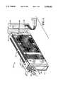
- FIG. 1is a perspective view of a modular computer component constructed according to the principles of the present invention
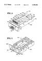
- FIG. 2is a first perspective view of a latch assembly secured to the modular computer component shown in FIG. 1;
- FIG. 3is a second perspective view of the latch assembly shown in FIG. 2;
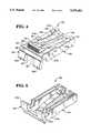
- FIG. 4is a first perspective view of a latch body forming a part of the latch assembly shown in FIGS. 2 and 3;
- FIG. 5is a second perspective view of the latch body shown in FIG. 4;
- FIG. 6is a perspective view a latch operator forming a part of the latch assembly shown in FIGS. 2 and 3;
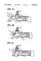
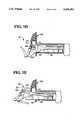
- FIGS. 7A-7Eare sectioned views of the latch assembly shown in FIGS. 2 and 3, illustrating the operation of the latch assembly relative to a computer housing;
- FIG. 8is a sectioned view of the latch body shown in FIGS. 4 and 5, including a light conduit passing through a portion of the latch body.
- a preferred embodiment of a modular computer component constructed according to the principles of the present inventionis designated generally as 400.
- the component 400is a media disc, but those skilled in the art will recognize that the principles of the present invention apply to modular computer components in general, including batteries, fans, printed circuit boards, and memory units.
- a latch assembly 100releasably secures the component 400 relative to a computer housing (as shown in FIGS. 7A-7E). As shown in FIGS. 2 and 3, the latch assembly 100 includes a latch body 200 and a latch operator 300.
- the latch body 200will be described with reference to integral first and second segments, designated as 210 and 220, respectively, in FIGS. 4 and 5.
- the first segment 210extends from a front end 211 to a rear end 212 and has substantially parallel sidewalls 213a and 213b.
- a top portion of the first segment 210defines first and second interface surfaces 214a and 214b, respectively, that are substantially perpendicular to the sidewalls 213a and 213b.
- the latch body 200is secured to one side 414 of the modular computer component 400.
- the first interface surface 214ais substantially flush with the side 414, and the second interface surface 214b lies directly beneath the side 414.
- Screws 424a and 424bpass through holes 444a and 444b in the side 414 and mate with threaded holes 244a and 244b, shown in FIG. 2, in the latch body 200 near the rear end 212.
- the second segment 220 of the latch body 200is integrally joined to the front end 211 of the first segment 210, extending at an oblique angle relative to the first interface surface 214a.
- the second segment 220functions as a front panel member 221 that includes a first flange 222a and a second flange 222b, defining a gap 223 therebetween.
- the flanges 222a and 222bprovide support behind which a person can place one or more fingers in order to grasp and handle the modular unit to which the latch assembly 100 is secured.
- An aperture 260is provided in the front panel 221 to allow for the passage of light outside the latch assembly.
- a stop member 250is cantilevered relative to the rear end 212 of the first segment 210 and includes resilient arm members 255a and 255b that are integrally joined to the rear end 212 and extend toward the front end 211.
- a forward portion of the stop member 250extends above the first interface surface 214a to define a catch member 251.
- the catch member 251includes a leading or first inclined surface 252 and a trailing or second inclined surface 253.
- the surfaces 252 and 253may be described as inclined or oblique relative to the first interface surface 214a.
- the leading surface 252is relatively farther from and slopes away from the front end 211.
- the trailing surface 253is relatively nearer to and slopes toward the front end 211.
- the surfaces 252 and 253define the depth or thickness of the catch member 251 therebetween, which depth progressively decreases as a function of the height of the catch member 251 relative to the first interface surface 214a.
- the resilient nature of the arm members 255a and 255ballows the catch member 251 to deflect among a plurality of positions relative to the first interface surface 214a.
- the stop member 250provides a means for latching the component 400 relative to a computer housing.
- the arm members 255a and 255bdefine a longitudinal slot 256 therebetween, which slot 256 extends substantially the entire length of the stop member 250.
- the slot 256is occupied by a lever member 356 comprising a portion of the latch operator 300. As shown in FIG. 6, the lever member 356 extends between a front end 311 and a rear end 312 of the latch operator 300.
- the slot 256 in the stop member 250proceeds into a recess 257 in the catch member 251.
- the recess 257is occupied by an elevated crossbar 357 on the latch operator 300, which extends laterally from a central portion of the lever member 356.
- the rear end 312 of the latch operator 300is secured to the rear end 212 of the latch body 200 to cantilever the latch operator relative to the rear end 212 of the latch body.
- the front end 311 of the latch operator 300extends through the gap 223 and includes a tab or operator member 313 to be manually operated in a manner described below.
- the spatial relationship between the crossbar 357 and the catch member 251is such that downward movement of the crossbar 357 necessarily causes downward movement of the catch member 251, but downward movement of the catch member 251 does not cause downward movement of the crossbar 357.
- the latch operator 300provides a means for unlatching the component 400 relative to a computer housing.
- FIGS. 7A-7Ethe operation of the latch assembly 100 is shown in relation to a computer housing 500.
- the leading surface 252(as shown in FIGS. 2 and 4, not visible in FIGS. 7A-7E) and a portion of the lever member 356 contact a lip 512 that defines one wall of a notch 511 in the computer housing 500 (as shown in FIG. 7A) .
- the catch member 251 and the lever member 356deflect away from the lip 512, allowing the further insertion of the component into the housing (as shown in FIG. 7B).
- the bias in the lever member 356causes the crossbar 357 to deflect into the notch 511, and the lever member 356 to deflect into a void 513 in a second, opposing wall 514 of the notch 511.
- the trailing surface 253passes beyond the lip 512, at which time the bias in the stop member 250 (as shown in FIGS. 2 and 4, not visible in FIGS. 7A-7E) urges the catch member 251 into the notch 511 (as shown in FIG. 7C).
- the trailing surface 253is biased against the first notch wall 512 to prevent any undesired movement of the component relative to the housing.
- the trailing surface 253is formed with a series of successive square edges designed to selectively engage the first notch wall 512 when the catch mechanism 251 protrudes into the notch 511.
- an interconnecting plug 450 at the rear of the component 400engages an interconnecting receptacle 540 at the rear of the computer housing 500.
- the receptacle 540is in communication with a computer 550 that is serviced by the components within the housing 500.
- the length of the component relative to the length of the housingensures that the component automatically interconnects with the computer, and also, prevents over-insertion of the component into the housing.
- a personplaces his forefinger 901 behind one flange 222b and his middle finger 902 behind the other flange 222a; pushes his thumb 903 against the tab 313 to exert a first force F1 that unlatches the component from the housing; and pulls against the flanges 222a and 222b to exert a second force F2 that disconnects the component from the computer and removes s the component from the housing (as shown in FIGS. 7D and 7E).
- the unlatching force F1 against the tab 313translates into a force on the catch member 251 away from the notch 511, thereby pulling the trailing surface 253 out of engagement with the lip 512.
- the removal force F2must be sufficient to pull the plug 450 out of engagement with the receptacle 540.
- a transparent light conduit 600passes through a portion of the latch body 200.
- the light conduit 600conducts light from a source 560 within a computer housing to the exterior of the housing.
- the light conduit 600extends from a front end 611 proximate the front panel 221 to a rear end 612 proximate the light source 560 at the rear end 212 of the latch body 200.
- the light conduit 600is a translucent plastic member that is tinted yellow to make light exiting the front end 611 appear similar in color to light entering the rear end 612. In a preferred embodiment, the light indicates when the component is activated.
Landscapes
- Engineering & Computer Science (AREA)
- Microelectronics & Electronic Packaging (AREA)
- Details Of Connecting Devices For Male And Female Coupling (AREA)
Abstract
Description
Claims (7)
Priority Applications (1)
| Application Number | Priority Date | Filing Date | Title |
|---|---|---|---|
| US07/921,160US5359492A (en) | 1992-07-29 | 1992-07-29 | Latch assembly for modular computer component |
Applications Claiming Priority (1)
| Application Number | Priority Date | Filing Date | Title |
|---|---|---|---|
| US07/921,160US5359492A (en) | 1992-07-29 | 1992-07-29 | Latch assembly for modular computer component |
Publications (1)
| Publication Number | Publication Date |
|---|---|
| US5359492Atrue US5359492A (en) | 1994-10-25 |
Family
ID=25445005
Family Applications (1)
| Application Number | Title | Priority Date | Filing Date |
|---|---|---|---|
| US07/921,160Expired - LifetimeUS5359492A (en) | 1992-07-29 | 1992-07-29 | Latch assembly for modular computer component |
Country Status (1)
| Country | Link |
|---|---|
| US (1) | US5359492A (en) |
Cited By (37)
| Publication number | Priority date | Publication date | Assignee | Title |
|---|---|---|---|---|
| USD373349S (en) | 1995-05-05 | 1996-09-03 | Hewlett-Packard Co. | Mass termination block |
| US5668654A (en)* | 1995-05-30 | 1997-09-16 | The Whitaker Corporation | Package for an infrared communications adapter |
| US5797767A (en)* | 1996-05-31 | 1998-08-25 | Berg Technology, Inc. | Indicator light modular jack |
| US5858509A (en)* | 1996-11-15 | 1999-01-12 | Digital Equipment Corporation | Attenuating vibrations in a mounting shelf for multiple disk drives |
| US5876239A (en)* | 1996-08-30 | 1999-03-02 | The Whitaker Corporation | Electrical connector having a light indicator |
| US5946196A (en)* | 1996-07-16 | 1999-08-31 | Samsung Electronics Co., Ltd. | Device for securing a printed circuit board assembly |
| US6069789A (en)* | 1996-10-28 | 2000-05-30 | Samsung Electronics Co., Ltd. | Mounting apparatus for auxiliary storage device of computer |
| US6166919A (en)* | 1997-12-16 | 2000-12-26 | Notrel Networks Corporation | Casing mountable filler module |
| US6181549B1 (en)* | 1997-06-24 | 2001-01-30 | Dell Products, L.P. | Chassis retaining system for an electronics rack |
| US6185103B1 (en)* | 1998-09-03 | 2001-02-06 | Fujitsu Limited | Releasable disk drive for electronic devices |
| US6264499B1 (en) | 1999-03-02 | 2001-07-24 | Tyco Electronics Corp. | Electronic module guide frame having light transmission members |
| US6301099B1 (en)* | 1998-04-14 | 2001-10-09 | Compaq Computer Corporation | Computer having option card module latching and drive bay pivot structures |
| US6356441B1 (en)* | 2000-04-18 | 2002-03-12 | Emc Corporation | Disk drive assembly with improved securing and releasing mechanism |
| US6359778B1 (en)* | 2000-09-12 | 2002-03-19 | Wen-Kao Wu | Removable-type hard disk drive bi-directional ingress and egress structure |
| US6373698B1 (en)* | 2001-05-03 | 2002-04-16 | International Business Machines Corporation | Apparatus for cooling a computer system |
| US6535390B1 (en)* | 1999-05-17 | 2003-03-18 | Delta Electronics, Inc. | Securing device and electronic appliance assembly applying the same |
| US6549969B1 (en)* | 2000-02-29 | 2003-04-15 | International Business Machines Corporation | Interlock for preventing human error in hot pluggable systems |
| US6556437B1 (en) | 2000-08-10 | 2003-04-29 | Dell Products L.P. | Ergonomic carrier for hot-swap computer components |
| US20030161101A1 (en)* | 2001-06-29 | 2003-08-28 | Hillyard David R. | High availability small foot-print server |
| US6618259B1 (en)* | 2002-05-16 | 2003-09-09 | Dell Products L.P. | Push-pull latch cartridge with integrated cantilever latch |
| US6623292B1 (en)* | 2000-10-27 | 2003-09-23 | Fci Americas Technology, Inc. | Card edge connector adapted to provide visual status indication |
| USD481393S1 (en) | 2002-11-14 | 2003-10-28 | International Business Machines Corporation | Server module for a computer system |
| US6674641B2 (en)* | 2001-07-16 | 2004-01-06 | Dell Products L.P. | Latch for computer chassis fan assembly |
| US20040008500A1 (en)* | 2002-07-09 | 2004-01-15 | Larson Thane M. | Ejector latch indicator light |
| US20040029435A1 (en)* | 2002-08-08 | 2004-02-12 | Larson Thane M | Ejector latch indicator light and connector |
| USD487090S1 (en) | 2002-06-18 | 2004-02-24 | Sun Microsystems, Inc. | Computer equipment |
| US20040061997A1 (en)* | 2002-09-30 | 2004-04-01 | Skinner David N. | Light-emitting lock device control element and electronic device including the same |
| US20040117946A1 (en)* | 2002-12-20 | 2004-06-24 | Kuo-Chih Lin | Latch for removing a cover from a base |
| USD494159S1 (en) | 2002-06-18 | 2004-08-10 | Sun Microsystems, Inc. | Computer apparatus |
| USD496039S1 (en) | 2003-08-14 | 2004-09-14 | International Business Machines Corporation | Cam latch assembly for a computer system |
| US7106596B1 (en)* | 2004-07-23 | 2006-09-12 | Sun Microsystems, Inc. | Component removal apparatus |
| US7121638B1 (en)* | 2002-05-07 | 2006-10-17 | Snap-On Incorporated | Drawer latch |
| US20070238011A1 (en)* | 2006-04-07 | 2007-10-11 | Wolf Matthias | Battery pack |
| US20130149028A1 (en)* | 2011-12-09 | 2013-06-13 | Det International Holding Limited | Locking device |
| US20170042060A1 (en)* | 2015-08-07 | 2017-02-09 | Quanta Computer Inc. | Quick release fan module |
| DE102016121347A1 (en)* | 2016-11-08 | 2018-05-09 | Bürkert Werke GmbH | Electronic module for I / O module system |
| US20190364681A1 (en)* | 2018-05-22 | 2019-11-28 | Sumitomo Electric Lightwave Corp. | Panel door for a network enclosure box |
Citations (11)
| Publication number | Priority date | Publication date | Assignee | Title |
|---|---|---|---|---|
| US2609268A (en)* | 1948-12-08 | 1952-09-02 | Nye Robert Glen | Mechanical pressure latch |
| US3853379A (en)* | 1973-07-20 | 1974-12-10 | Itt | Printed circuit board connector assembly |
| US4232356A (en)* | 1979-02-07 | 1980-11-04 | Burroughs Corporation | Logic card frame |
| US4914550A (en)* | 1987-04-03 | 1990-04-03 | Vdo Adolf Schindling Ag | Device for the arranging of an electronic component, particularly a module having circuit boards |
| US4922125A (en)* | 1988-03-17 | 1990-05-01 | International Business Machines Corporation | System cable assembly and component packaging |
| US4947289A (en)* | 1989-10-19 | 1990-08-07 | Northern Telecom Limited | Latch mechanism for a plug-in cartridge or the like |
| US4982303A (en)* | 1988-10-31 | 1991-01-01 | Zenith Data Systems Corporation | Removable hard disk drive having a combination latch, lever and handle |
| US4996631A (en)* | 1989-10-30 | 1991-02-26 | Canoga Industries, Inc. | Injector/ejector system for rack mounted plug-in modules with front panels |
| US5045960A (en)* | 1989-06-13 | 1991-09-03 | Zenith Data Systems Corporation | Self-aligning guide and track for removable disk drive module |
| US5068652A (en)* | 1989-06-23 | 1991-11-26 | Kabushiki Kaisha Toshiba | Personal computer having condition indicator |
| US5202197A (en)* | 1991-10-17 | 1993-04-13 | International Business Machines Corporation | Data processing device having an improved manually operated battery eject mechanism and a warning light |
- 1992
- 1992-07-29USUS07/921,160patent/US5359492A/ennot_activeExpired - Lifetime
Patent Citations (11)
| Publication number | Priority date | Publication date | Assignee | Title |
|---|---|---|---|---|
| US2609268A (en)* | 1948-12-08 | 1952-09-02 | Nye Robert Glen | Mechanical pressure latch |
| US3853379A (en)* | 1973-07-20 | 1974-12-10 | Itt | Printed circuit board connector assembly |
| US4232356A (en)* | 1979-02-07 | 1980-11-04 | Burroughs Corporation | Logic card frame |
| US4914550A (en)* | 1987-04-03 | 1990-04-03 | Vdo Adolf Schindling Ag | Device for the arranging of an electronic component, particularly a module having circuit boards |
| US4922125A (en)* | 1988-03-17 | 1990-05-01 | International Business Machines Corporation | System cable assembly and component packaging |
| US4982303A (en)* | 1988-10-31 | 1991-01-01 | Zenith Data Systems Corporation | Removable hard disk drive having a combination latch, lever and handle |
| US5045960A (en)* | 1989-06-13 | 1991-09-03 | Zenith Data Systems Corporation | Self-aligning guide and track for removable disk drive module |
| US5068652A (en)* | 1989-06-23 | 1991-11-26 | Kabushiki Kaisha Toshiba | Personal computer having condition indicator |
| US4947289A (en)* | 1989-10-19 | 1990-08-07 | Northern Telecom Limited | Latch mechanism for a plug-in cartridge or the like |
| US4996631A (en)* | 1989-10-30 | 1991-02-26 | Canoga Industries, Inc. | Injector/ejector system for rack mounted plug-in modules with front panels |
| US5202197A (en)* | 1991-10-17 | 1993-04-13 | International Business Machines Corporation | Data processing device having an improved manually operated battery eject mechanism and a warning light |
Cited By (49)
| Publication number | Priority date | Publication date | Assignee | Title |
|---|---|---|---|---|
| USD373349S (en) | 1995-05-05 | 1996-09-03 | Hewlett-Packard Co. | Mass termination block |
| US5668654A (en)* | 1995-05-30 | 1997-09-16 | The Whitaker Corporation | Package for an infrared communications adapter |
| US5797767A (en)* | 1996-05-31 | 1998-08-25 | Berg Technology, Inc. | Indicator light modular jack |
| US5946196A (en)* | 1996-07-16 | 1999-08-31 | Samsung Electronics Co., Ltd. | Device for securing a printed circuit board assembly |
| US5876239A (en)* | 1996-08-30 | 1999-03-02 | The Whitaker Corporation | Electrical connector having a light indicator |
| US6069789A (en)* | 1996-10-28 | 2000-05-30 | Samsung Electronics Co., Ltd. | Mounting apparatus for auxiliary storage device of computer |
| US5858509A (en)* | 1996-11-15 | 1999-01-12 | Digital Equipment Corporation | Attenuating vibrations in a mounting shelf for multiple disk drives |
| US6181549B1 (en)* | 1997-06-24 | 2001-01-30 | Dell Products, L.P. | Chassis retaining system for an electronics rack |
| US6166919A (en)* | 1997-12-16 | 2000-12-26 | Notrel Networks Corporation | Casing mountable filler module |
| US6661654B2 (en) | 1998-04-14 | 2003-12-09 | Hewlett-Packard Development Company, L.P. | Computer having option card module latching and drive bay pivot structures |
| US6301099B1 (en)* | 1998-04-14 | 2001-10-09 | Compaq Computer Corporation | Computer having option card module latching and drive bay pivot structures |
| US6185103B1 (en)* | 1998-09-03 | 2001-02-06 | Fujitsu Limited | Releasable disk drive for electronic devices |
| US6264499B1 (en) | 1999-03-02 | 2001-07-24 | Tyco Electronics Corp. | Electronic module guide frame having light transmission members |
| US6535390B1 (en)* | 1999-05-17 | 2003-03-18 | Delta Electronics, Inc. | Securing device and electronic appliance assembly applying the same |
| US6549969B1 (en)* | 2000-02-29 | 2003-04-15 | International Business Machines Corporation | Interlock for preventing human error in hot pluggable systems |
| US6356441B1 (en)* | 2000-04-18 | 2002-03-12 | Emc Corporation | Disk drive assembly with improved securing and releasing mechanism |
| US6556437B1 (en) | 2000-08-10 | 2003-04-29 | Dell Products L.P. | Ergonomic carrier for hot-swap computer components |
| US6359778B1 (en)* | 2000-09-12 | 2002-03-19 | Wen-Kao Wu | Removable-type hard disk drive bi-directional ingress and egress structure |
| US6623292B1 (en)* | 2000-10-27 | 2003-09-23 | Fci Americas Technology, Inc. | Card edge connector adapted to provide visual status indication |
| US6373698B1 (en)* | 2001-05-03 | 2002-04-16 | International Business Machines Corporation | Apparatus for cooling a computer system |
| US20030161101A1 (en)* | 2001-06-29 | 2003-08-28 | Hillyard David R. | High availability small foot-print server |
| US6654241B2 (en)* | 2001-06-29 | 2003-11-25 | Intel Corporation | High availability small foot-print server |
| US6674641B2 (en)* | 2001-07-16 | 2004-01-06 | Dell Products L.P. | Latch for computer chassis fan assembly |
| US7121638B1 (en)* | 2002-05-07 | 2006-10-17 | Snap-On Incorporated | Drawer latch |
| US6618259B1 (en)* | 2002-05-16 | 2003-09-09 | Dell Products L.P. | Push-pull latch cartridge with integrated cantilever latch |
| USD487090S1 (en) | 2002-06-18 | 2004-02-24 | Sun Microsystems, Inc. | Computer equipment |
| USD494159S1 (en) | 2002-06-18 | 2004-08-10 | Sun Microsystems, Inc. | Computer apparatus |
| US6829150B2 (en)* | 2002-07-09 | 2004-12-07 | Hewlett-Packard Development Company, L.P. | Ejector latch indicator light |
| US20040008500A1 (en)* | 2002-07-09 | 2004-01-15 | Larson Thane M. | Ejector latch indicator light |
| GB2390746B (en)* | 2002-07-09 | 2006-03-29 | Hewlett Packard Development Co | Ejector latch indicator light |
| US20040029435A1 (en)* | 2002-08-08 | 2004-02-12 | Larson Thane M | Ejector latch indicator light and connector |
| US6908333B2 (en)* | 2002-08-08 | 2005-06-21 | Hewlett-Packard Development Company, L.P. | Ejector latch indicator light and connector |
| US6717804B1 (en)* | 2002-09-30 | 2004-04-06 | Hewlett-Packard Development Company, L.P. | Light-emitting lock device control element and electronic device including the same |
| US20040061997A1 (en)* | 2002-09-30 | 2004-04-01 | Skinner David N. | Light-emitting lock device control element and electronic device including the same |
| USD481393S1 (en) | 2002-11-14 | 2003-10-28 | International Business Machines Corporation | Server module for a computer system |
| US20040117946A1 (en)* | 2002-12-20 | 2004-06-24 | Kuo-Chih Lin | Latch for removing a cover from a base |
| US6824174B2 (en)* | 2002-12-20 | 2004-11-30 | Hon Hai Precision Ind. Co., Ltd. | Latch for removing a cover from a base |
| USD496039S1 (en) | 2003-08-14 | 2004-09-14 | International Business Machines Corporation | Cam latch assembly for a computer system |
| US7106596B1 (en)* | 2004-07-23 | 2006-09-12 | Sun Microsystems, Inc. | Component removal apparatus |
| DE102006018005B4 (en)* | 2006-04-07 | 2014-01-30 | Robert Bosch Gmbh | Battery pack and electrical appliance |
| US20070238011A1 (en)* | 2006-04-07 | 2007-10-11 | Wolf Matthias | Battery pack |
| US7670714B2 (en)* | 2006-04-07 | 2010-03-02 | Robert Bosch Gmbh | Battery pack |
| US20130149028A1 (en)* | 2011-12-09 | 2013-06-13 | Det International Holding Limited | Locking device |
| US20170042060A1 (en)* | 2015-08-07 | 2017-02-09 | Quanta Computer Inc. | Quick release fan module |
| US10470336B2 (en)* | 2015-08-07 | 2019-11-05 | Quanta Computer Inc. | Quick release fan module |
| DE102016121347A1 (en)* | 2016-11-08 | 2018-05-09 | Bürkert Werke GmbH | Electronic module for I / O module system |
| US10249987B2 (en) | 2016-11-08 | 2019-04-02 | Buerkert Werke Gmbh & Co. Kg | Electronic module for an I/O modular system |
| DE102016121347B4 (en)* | 2016-11-08 | 2020-12-31 | Bürkert Werke GmbH | Electronic module for I / O module system |
| US20190364681A1 (en)* | 2018-05-22 | 2019-11-28 | Sumitomo Electric Lightwave Corp. | Panel door for a network enclosure box |
Similar Documents
| Publication | Publication Date | Title |
|---|---|---|
| US5359492A (en) | Latch assembly for modular computer component | |
| US6754074B2 (en) | Multipurpose server handle | |
| CA2684108C (en) | Connector of a simple structure having a locking mechanism | |
| US7422457B1 (en) | Plug-in module with improved latch mechanism | |
| US5993241A (en) | Modular, redundant, hot swappable, blind mate power supply system | |
| US5340340A (en) | Apparatus for removably supporting a plurality of hot plug-connected hard disk drives | |
| US6373690B1 (en) | Apparatus for mounting a panel to a chassis of a computer | |
| US6715850B1 (en) | Computer with removable panels | |
| CN2548305Y (en) | Small pluggable module | |
| US5868261A (en) | Anti-slamming latch apparatus for modular component installations | |
| US5203718A (en) | Connector | |
| US7023693B2 (en) | Mounting apparatus for peripheral device | |
| US6355991B1 (en) | Hot plug switch mechanism | |
| US6011687A (en) | Docking station adapter for computer media modules | |
| US6272005B1 (en) | Apparatus for removably mounting a system component in a computer | |
| US9398715B2 (en) | Electronic module shelf assembly and methods | |
| US5734549A (en) | Disk drive unit for a magnetic disk system | |
| US6236573B1 (en) | Apparatus and method for single-handed manipulation of latching pluggable electronic component | |
| US5232374A (en) | Lock eject mechanism for electrical connectors | |
| US4709975A (en) | Releasable snap connector | |
| US4589716A (en) | Releasable snap connector | |
| US6216339B1 (en) | Tool-actuated ejector mechanism for extracting electronic modular components | |
| CN2631002Y (en) | Optical disc drive button structure assembly | |
| US5198627A (en) | Electronic module switch and power and interlock system | |
| EP0678942B1 (en) | Connector |
Legal Events
| Date | Code | Title | Description |
|---|---|---|---|
| AS | Assignment | Owner name:NCR CORPORATION, A MD CORP., OHIO Free format text:ASSIGNMENT OF ASSIGNORS INTEREST.;ASSIGNOR:PORTER, WARREN W.;REEL/FRAME:006195/0988 Effective date:19920715 | |
| STCF | Information on status: patent grant | Free format text:PATENTED CASE | |
| FPAY | Fee payment | Year of fee payment:4 | |
| FPAY | Fee payment | Year of fee payment:8 | |
| FEPP | Fee payment procedure | Free format text:PAYOR NUMBER ASSIGNED (ORIGINAL EVENT CODE: ASPN); ENTITY STATUS OF PATENT OWNER: LARGE ENTITY Free format text:PAYER NUMBER DE-ASSIGNED (ORIGINAL EVENT CODE: RMPN); ENTITY STATUS OF PATENT OWNER: LARGE ENTITY | |
| AS | Assignment | Owner name:STEINMETZ ELECTRICAL LLC, CALIFORNIA Free format text:ASSIGNMENT OF ASSIGNORS INTEREST;ASSIGNOR:NCR CORPORATION;REEL/FRAME:015428/0845 Effective date:20040623 | |
| FPAY | Fee payment | Year of fee payment:12 | |
| AS | Assignment | Owner name:INTELLECTUAL VENTURES I LLC, DELAWARE Free format text:MERGER;ASSIGNOR:STEINMETZ ELECTRICAL LLC;REEL/FRAME:025467/0109 Effective date:20101207 |