US5359454A - Apparatus for providing autostereoscopic and dynamic images - Google Patents
Apparatus for providing autostereoscopic and dynamic imagesDownload PDFInfo
- Publication number
- US5359454A US5359454AUS07/931,871US93187192AUS5359454AUS 5359454 AUS5359454 AUS 5359454AUS 93187192 AUS93187192 AUS 93187192AUS 5359454 AUS5359454 AUS 5359454A
- Authority
- US
- United States
- Prior art keywords
- light control
- optics
- light
- image
- zones
- Prior art date
- Legal status (The legal status is an assumption and is not a legal conclusion. Google has not performed a legal analysis and makes no representation as to the accuracy of the status listed.)
- Expired - Lifetime
Links
Images


Classifications
- G—PHYSICS
- G02—OPTICS
- G02B—OPTICAL ELEMENTS, SYSTEMS OR APPARATUS
- G02B3/00—Simple or compound lenses
- G02B3/0006—Arrays
- G02B3/0037—Arrays characterized by the distribution or form of lenses
- G02B3/005—Arrays characterized by the distribution or form of lenses arranged along a single direction only, e.g. lenticular sheets
- B—PERFORMING OPERATIONS; TRANSPORTING
- B29—WORKING OF PLASTICS; WORKING OF SUBSTANCES IN A PLASTIC STATE IN GENERAL
- B29C—SHAPING OR JOINING OF PLASTICS; SHAPING OF MATERIAL IN A PLASTIC STATE, NOT OTHERWISE PROVIDED FOR; AFTER-TREATMENT OF THE SHAPED PRODUCTS, e.g. REPAIRING
- B29C39/00—Shaping by casting, i.e. introducing the moulding material into a mould or between confining surfaces without significant moulding pressure; Apparatus therefor
- B29C39/02—Shaping by casting, i.e. introducing the moulding material into a mould or between confining surfaces without significant moulding pressure; Apparatus therefor for making articles of definite length, i.e. discrete articles
- B29C39/026—Shaping by casting, i.e. introducing the moulding material into a mould or between confining surfaces without significant moulding pressure; Apparatus therefor for making articles of definite length, i.e. discrete articles characterised by the shape of the surface
- B—PERFORMING OPERATIONS; TRANSPORTING
- B29—WORKING OF PLASTICS; WORKING OF SUBSTANCES IN A PLASTIC STATE IN GENERAL
- B29D—PRODUCING PARTICULAR ARTICLES FROM PLASTICS OR FROM SUBSTANCES IN A PLASTIC STATE
- B29D11/00—Producing optical elements, e.g. lenses or prisms
- B29D11/00009—Production of simple or compound lenses
- B29D11/00278—Lenticular sheets
- G—PHYSICS
- G02—OPTICS
- G02B—OPTICAL ELEMENTS, SYSTEMS OR APPARATUS
- G02B30/00—Optical systems or apparatus for producing three-dimensional [3D] effects, e.g. stereoscopic images
- G02B30/20—Optical systems or apparatus for producing three-dimensional [3D] effects, e.g. stereoscopic images by providing first and second parallax images to an observer's left and right eyes
- G02B30/26—Optical systems or apparatus for producing three-dimensional [3D] effects, e.g. stereoscopic images by providing first and second parallax images to an observer's left and right eyes of the autostereoscopic type
- G02B30/27—Optical systems or apparatus for producing three-dimensional [3D] effects, e.g. stereoscopic images by providing first and second parallax images to an observer's left and right eyes of the autostereoscopic type involving lenticular arrays
- G—PHYSICS
- G02—OPTICS
- G02B—OPTICAL ELEMENTS, SYSTEMS OR APPARATUS
- G02B5/00—Optical elements other than lenses
- G02B5/003—Light absorbing elements
- G—PHYSICS
- G03—PHOTOGRAPHY; CINEMATOGRAPHY; ANALOGOUS TECHNIQUES USING WAVES OTHER THAN OPTICAL WAVES; ELECTROGRAPHY; HOLOGRAPHY
- G03B—APPARATUS OR ARRANGEMENTS FOR TAKING PHOTOGRAPHS OR FOR PROJECTING OR VIEWING THEM; APPARATUS OR ARRANGEMENTS EMPLOYING ANALOGOUS TECHNIQUES USING WAVES OTHER THAN OPTICAL WAVES; ACCESSORIES THEREFOR
- G03B35/00—Stereoscopic photography
- G03B35/18—Stereoscopic photography by simultaneous viewing
- G03B35/24—Stereoscopic photography by simultaneous viewing using apertured or refractive resolving means on screens or between screen and eye
- G—PHYSICS
- G03—PHOTOGRAPHY; CINEMATOGRAPHY; ANALOGOUS TECHNIQUES USING WAVES OTHER THAN OPTICAL WAVES; ELECTROGRAPHY; HOLOGRAPHY
- G03F—PHOTOMECHANICAL PRODUCTION OF TEXTURED OR PATTERNED SURFACES, e.g. FOR PRINTING, FOR PROCESSING OF SEMICONDUCTOR DEVICES; MATERIALS THEREFOR; ORIGINALS THEREFOR; APPARATUS SPECIALLY ADAPTED THEREFOR
- G03F7/00—Photomechanical, e.g. photolithographic, production of textured or patterned surfaces, e.g. printing surfaces; Materials therefor, e.g. comprising photoresists; Apparatus specially adapted therefor
- G03F7/0005—Production of optical devices or components in so far as characterised by the lithographic processes or materials used therefor
- G03F7/001—Phase modulating patterns, e.g. refractive index patterns
- G—PHYSICS
- G03—PHOTOGRAPHY; CINEMATOGRAPHY; ANALOGOUS TECHNIQUES USING WAVES OTHER THAN OPTICAL WAVES; ELECTROGRAPHY; HOLOGRAPHY
- G03F—PHOTOMECHANICAL PRODUCTION OF TEXTURED OR PATTERNED SURFACES, e.g. FOR PRINTING, FOR PROCESSING OF SEMICONDUCTOR DEVICES; MATERIALS THEREFOR; ORIGINALS THEREFOR; APPARATUS SPECIALLY ADAPTED THEREFOR
- G03F7/00—Photomechanical, e.g. photolithographic, production of textured or patterned surfaces, e.g. printing surfaces; Materials therefor, e.g. comprising photoresists; Apparatus specially adapted therefor
- G03F7/0035—Multiple processes, e.g. applying a further resist layer on an already in a previously step, processed pattern or textured surface
- B—PERFORMING OPERATIONS; TRANSPORTING
- B29—WORKING OF PLASTICS; WORKING OF SUBSTANCES IN A PLASTIC STATE IN GENERAL
- B29C—SHAPING OR JOINING OF PLASTICS; SHAPING OF MATERIAL IN A PLASTIC STATE, NOT OTHERWISE PROVIDED FOR; AFTER-TREATMENT OF THE SHAPED PRODUCTS, e.g. REPAIRING
- B29C35/00—Heating, cooling or curing, e.g. crosslinking or vulcanising; Apparatus therefor
- B29C35/02—Heating or curing, e.g. crosslinking or vulcanizing during moulding, e.g. in a mould
- B29C35/08—Heating or curing, e.g. crosslinking or vulcanizing during moulding, e.g. in a mould by wave energy or particle radiation
- B29C35/0805—Heating or curing, e.g. crosslinking or vulcanizing during moulding, e.g. in a mould by wave energy or particle radiation using electromagnetic radiation
- B29C2035/0827—Heating or curing, e.g. crosslinking or vulcanizing during moulding, e.g. in a mould by wave energy or particle radiation using electromagnetic radiation using UV radiation
Definitions
- the present inventionrelates to the production and display of autostereoscopic and dynamic images, and more particularly to a technique for producing autostereoscopic and dynamic images in thin-film material.
- the present inventionfurther relates to the production of specialized light control films and to the surface figuring of plastic film useful for the production of such images.
- image display methodswhich enable the presentation of multiple images from different viewing angles fall into three broad categories: projection-type (non-holographic) displays, lens-sheet displays and holographic displays. Any of these methods can be used to display autostereoscopic depth images, motion images and color changing images.
- a barrier strip display deviceconsists of an interleaved image which typically consists of strips taken from each of the images that are to be displayed.
- the strips comprising each of the imagesare interleaved parallel to each other so that every Nth strip is from the same image, where N is the number of images. This number may be as small as two or as large as nineteen or more.
- the interleaved imageis disposed in close proximity to and parallel to a viewing mask.
- the viewing maskcontains parallel opaque lines of equal width which are separated by transparent zones having a uniform width which is equal to or less than that of the opaque lines.
- Barrier strip imagesare usually viewed from the mask side by means of light transmitted through the interleaved image and the mask.
- the intensity of the back illumination requireddepends on the brightness of the viewing environment and on the number of images which are interleaved.
- the color that is perceived at a particular point and at a particular viewing angle with a barrier strip display deviceis determined by the color of the image strip which is visible through the mask at that point.
- barrier stripsare capable of displaying autostereoscopic images
- a barrier strip display devicewill produce this effect only when certain conditions are satisfied.
- the mask linesmust lie in a plane orthogonal to that of the observer's eyes.
- the width and spacing of the transparent mask lines and the distance from the interleaved image to the maskmust be such that each of the viewer's eyes sees different, non-overlapping regions of the interleaved image through the transparent mask lines.
- the interleaved imagemust have been constructed such that each of the image lines visible to the right eye is part of a right eye stereo pair image, and the image lines visible to the left eye are each part of a matching left eye stereo pair image.
- the distances and positions at which stereoscopic depth is perceivedis restricted by the geometry of the mask, the number of interleaved images and the mask-to-image distance.
- barrier strip image devicesIn addition to the difficulty in achieving an autostereoscopic effect, a significant limitation on barrier strip image devices is that the thickness of such a device is governed by the number of images it presents, the width of the image strips and the intended viewing distance. The distance between the barrier strips mask and the interleaved image is generally a large multiple of the width of a single image strip. A typical barrier strip device has a thickness of about six (6) millimeters, making it an unacceptable technology for mass production. The barrier strip method is further limited in that it is only useful as a back-illuminated image display method.
- Integral photographyinvolves photographing an image through a plastic sheet into which small fly's-eye lenses (typically 50,000 lenses per sheet) have been impressed. The lenses cause a complete reproduction of the photographed image to be reproduced behind each tiny lens. This approach can recreate a visually complete three-dimensional image, but can only be reproduced at great expense.
- a further limitation of this lens sheetis that the images are at such a fine resolution that they cannot be reproduced on printing presses, but have to be reproduced photographically. Images produced by this method also have a very restricted viewing angle within which the image reconstructs correctly.
- the integram approach to lens-sheet displaysis a complex extension of the fly-eye approach. It involves positioning the captured image along a precisely curved surface (dimensionally matching the focal surface of the fly-eye lens) to overcome the viewing angle restrictions. The expense and difficulty in producing high quality three-dimensional images with this method, however, have prevented any large scale commercial success.
- a third method of the lens-sheet display technique currently knownis the lenticular screen display device.
- a lenticular screen display deviceemploys an array of cylindrical lenses to control the viewing angle of interleaved image strip. The lenses are disposed parallel to the image strips between the observer and the image strips such that the image strips directly underneath a lens lies at or near the lens' focal plane. The range of angles through which the image will be visible is determined by the position of each image strip underneath the lens array. As with the barrier strip method, the color of the image strip determines the color that will be perceived at the point of the lenticular screen processed image.
- a significant limitation on the lenticular screen display deviceis that its thickness is dependent on the width of the image strips. The thickness also is limited by the number of images presented, the designed viewing distance, and the focal properties of the lens. The thickness of these devices is in general greater than the width of the image strip multiplied by the number of images. As a result, a typical lenticular screen display device has a thickness of about one (1) millimeter, making it relatively expensive for mass production, and generally too thick for automated printing press equipment.
- the third broad category of currently known methods of producing and displaying autostereoscopic imagesis holographic displays.
- Holographic displaysuse holograms to reconstruct the appearance of an object over an angular range of view without the use of a lens.
- a hologramis a record of a diffraction pattern representing an object as viewed from a certain range of positions.
- White light viewable hologramsare generally either monochromatic or display a rainbow coloration which varies according to the viewing angle. Holograms are capable of displaying autostereoscopic, motion, combined autostereoscopic and motion, and color-change images. However, creating and reproducing a high quality hologram is a time-consuming and difficult process. Holograms cannot be created by printing and are not easily combined with the mass production of printed articles. Holograms are expensive and difficult to originate. They also require special equipment to impress onto a printing substrate. Because of their restrictive viewing conditions and limited control of color, the practical applications of holographic displays is very limited.
- the present inventioncomprises an apparatus for producing thin-film autostereoscopic and dynamic images.
- the present inventiondiffers from a conventional lenticular screen display structure in that the thickness of the present structure is independent of the width of the image strips.
- the inventionis therefore capable of producing autostereoscopic and dynamic images with a structure that is approximately as thin as conventional typing paper, on the order of two to three (2-3) mils, or 50 to 75 microns, thick. This is accomplished through the use of a light control material comprised of a multi-layer optical system.
- the first layer of the optical system(generally referred to as the "outer optic", i.e., the layer closest to the observer) consists of focusing elements.
- the second layerconsists of light control optics (often referred to as the "inner optic"). This layer is designed to provide directional control of the light passing out through the outer optic to the observer.
- the inner opticconsists of a pattern of bright zones disposed parallel to the axial direction of the outer optic lenses. Light absorbing or light dispersing zones (dark zones) separate the bright zones on the inner optic from each other.
- the inner and outer opticscooperate to perform the light directional control function. This differs from the conventional approach in which the light directional control function is performed solely by the position of each image element under the lenticular screen.
- the image to be displayedis divided into a number of image elements.
- the inner optic patternis designed to direct the light emitted from all the lenses associated with that image element in the same direction. If it is desirable to direct the light passing through the adjacent image element elsewhere, the inner optic pattern may be adjusted in that area to send all of the emitted light in the desired direction. The end result is that the present invention enables an observer to perceive one image element with one eye and a different image element with the other eye, thus creating the perception of autostereoscopic depth, motion or color change.
- the present inventionmay be used as a transmission material, in which case the bright zones of the inner optic are substantially transparent and the image is back-illuminated. It may also be used as a reflection material, in which case the bright zones of the inner optic may be specularly reflective, diffusively reflective, or may bear a reflective diffraction pattern which concentrates light from one direction and redirects it towards the observer.
- a low refractive index layerpreferably a polymer
- the polymercreates a smooth surface which is more suitable for printing than conventional devices.
- the position of the focusing optics and the light control opticsis reversed.
- the light control opticsincluding the bright and dark zones, is the outer layer of the light control material and the focusing optics are positioned underneath the light control optics.
- the light control material of the present inventionis intended for use with a series of image elements which have the effect of serving as a color filter.
- the image elementsmay be positioned between the focusing optics and the light control optics or to one side or the other of the bi-layer optics as described in more detail bellow. The positioning of the image elements is unrelated to the focal length of the focusing optics.
- a further object of the present inventionto provide a method for producing thin film images which display motion.
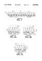
- FIG. 1is a cross-sectional view of a prior-art conventional lenticular screen structure.
- FIGS. 2a-care cross-sectional views of a conventional lenticular screen structure illustrating the direction of view from each of the right, center, and left image strips.
- FIGS. 3a-bare comparison scale drawings illustrating the thickness of a conventional lenticular screen structure and that of the present invention.
- FIG. 4is a cross-sectional view of a first embodiment according to the present invention including three image elements.
- FIG. 5is a cross-sectional view of the first embodiment of the present invention.
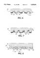
- FIG. 6shows a first alternative embodiment of the light control optics of the present invention.
- FIG. 7shows a second alternative embodiment of the light control optics of the present invention.
- FIG. 8shows a third alternative embodiment of the light control optics of the present invention.
- FIG. 9is a cross sectional view of another alternative embodiment of the present invention.
- FIG. 10is a cross-sectional view of a further alternative embodiment of the present invention.
- FIG. 11is a cross-sectional view of yet another alternative embodiment of the present invention.
- FIGS. 1 and 2a-cshow a conventional lenticular screen display device 20, which consists of a layer of optical material 21 bearing an array of cylindrical lenses 22 on its upper surface and an image 23 in contact with its lower surface.
- the image 23is generally supported upon a substrate 24.
- the image 23is typically created by interleaving image strips from a multiplicity of images. If, for example, three images are used, then image 23 would consist of right, center, and left image strips 26, 27 and 28.
- FIG. 2adepicts how the array of lenses 22 in the conventional lenticular screen display device 20 controls the direction of view of each of the right image strips 26.
- Light reflecting from each image strip 26is directed by the lenses 22 toward the observer's right eye.
- FIG. 2bdepicts that the center image strips 27 are located adjacent to the right image strips.
- the light reflected from the center image strips 27is directed by the lenses 22 in a slightly different direction than that of the right image strips. Light from these strips may be intercepted by the observer's left eye.
- an autostereoscopic imagethe observer would be viewing a stereo pair, different images with each eye, and would thus perceive a stereoscopic image.
- FIG. 1depicts how the array of lenses 22 in the conventional lenticular screen display device 20 controls the direction of view of each of the right image strips 26.
- FIG. 2bdepicts that the center image strips 27 are located adjacent to the right image strips.
- 2cdepicts how light reflecting from the left image strip is similarly directed in a third direction. If the observer's position changes such that the center image is intercepted by the right eye and the left image is intercepted by the left eye, a slightly different view of the autostereoscopic scene will be perceived, since right and center images comprise a stereo pair, and center and left comprise a stereo pair.
- the width of the individual lenses in the conventional lenticular screen methodmust be some multiple, n, of the image strip width, where n is an integer. Because of the limitations of the focusing optics 22, the thickness of the lens in a lenticular screen display device will also be some multiple of the print strip width 29, as shown in FIG. 3a.
- the minimum strip width of printed imagesis set by the smallest shape which can be reliably printed, which will generally be the size of a single print dot. Printing presses vary in their printing resolution, but a commercial printing press rarely exceeds a printing resolution of 175 lines/inch, or a print dot spacing of about six thousandths of an inch (152 microns). As a result, the width and thickness of a conventional lenticular screen device 20 can never be less and is typically much larger than the dimensions of the print dot spacing.
- the present inventioncircumvents this size limitation.
- the thickness of the present inventionis independent of the print dot spacing and the size of the print.
- FIG. 3billustrates the relative thickness of the present invention 30 for the same print width 29.
- FIGS. 3a and 3bare drawn to the same scale to show the magnitude of the difference between the thickness of a conventional lenticular screen device and that of the present invention for the same print width.
- the optical thickness of the present invention for images printed at 175 lines/inchwould typically fall in the range of from 1-3 mils, compared with 17 to 50 mils for a conventional lenticular screen device.
- the light control material 30comprises a two-layer optical system separated by a refractive material 36. It is the two-layer optical system that allows the thickness of the device to be independent of the print size.
- the first layercomprises focusing optics 31 and is sometimes referred to as the "outer optic” (i.e., closest to the observer).
- the focusing optics 31generally consist of an array of lens elements 35.
- the second layercontains light control optics 32 and is sometimes referred to as the "inner optic”.
- the layer of light control optics 32consists of a pattern of bright zones 33 disposed generally parallel to the axial direction of the focusing elements 35.
- the bright zones 33are separated from each other by dark zones 34, which may be either light absorbing or light dispersing.
- the composition of the focusing optics 31 and the light control optics 32will be discussed in detail below.
- FIG. 4also illustrates the cooperation of the focusing optics 31 and the light control optics 32 for light directional control.
- the light source(not shown) is located underneath the light control optics 32, and the light control material 30 is operating in a light transmissive mode.
- Three image elements(left image element 41, center image element 42, and right image element 43) are placed above the focusing optics 31. While FIG. 4 shows three image elements, the present invention is not limited to that number of image sets.
- the devicewill operate with as few as two sets of image elements (e.g., up/down or left/right) or with many more than that. Some applications which are not brightness sensitive could tolerate (and benefit from) a large number of image sets, such as four, five, or more.
- the relative positions of the image elements 41-43 and the focusing opticsalso is not important.
- the light directional control functionmay be performed with the image elements 41-43 placed either above the focusing optics 31 as shown in FIG. 4, in between the focusing optics 31 and the light control optics 32, or below the light control optics 32.
- the light control materialis divided into three image zones--a left image zone 51, a center image zone 52 and a right image zone 53.
- the center image zone 52is formed by positioning the associated bright zones 33 directly below the center of the lens elements 35. Light passing through the center image zone 52 will be directed through the focusing optics 31 above it and transmitted through the center image element 42 as center directed light (this light may be intercepted by the observer's right eye).
- the left image zone 51is formed by laterally shifting the position of the associated bright zones 33 to the right so that the center of the bright zones are no longer aligned with the center of the lens elements 35.
- Light passing through the left image zone 51will then be directed through the left image element 41 and transmitted as left directed light (this light may be intercepted by the observer's left eye, forming a stereo pair with the center image zone light directed to the right eye).
- the right image zone 53is similarly formed by laterally shifting the associated bright zones 33 to the left. Light passing through the right image zone 53 will be directed through the right image element 43 and transmitted as right directed light (if the observer's position shifts so that the center image light is intercepted by the observer' s left eye, then the right directed light may be intercepted by the observer's right eye, forming a stereo pair).
- the image elements 41-43will generally be composed of transparent, colored print dots that serve to color the light but will not control the directions of visibility of the lenses depicted.
- the resulting systemtherefore enables an observer to perceive one set of image elements from one eye and a different set of image elements from the other eye, thereby creating the perception of autostereoscopic depth, motion or color change.
- FIG. 4shows three sets of lenses 35 for each image element for simplicity.
- the number of lenses that are spanned by each image elementwill be a design variable, depending on the printing resolution, the width of the image elements, and the size of the lenses.
- the actual number of lenses devoted to a single image elementcan range from one lens to more than twenty. A typical number will be six to nine lenses per image element.
- the image elementsdo not necessarily have to cover the entire surface of the light control material. In general, each image element need only lie over its respective image zone, but the image elements do not have to be in perfect registration with the image zones. Also, the spacing between the image elements is not critical. Each image element does not have to be equally spaced from the edge of its respective image zone.
- FIG. 5shows the bright zones in the center image zone 52 aligned directly beneath the center of the associated lens elements 35, this alignment is not critical to the performance of the invention.
- the actual position of the lens elements over the light control opticsis not important. What is important is the pattern of the light control optics 32.
- the spacing of the bright zonesis periodic in each image zone so that the period of the bright zones matches the period of the lens elements. As long as the lateral spacing of the light control optics is fixed and the lateral positioning of the focusing optics is fixed, the relative positions of the two layers is not important. This allows “slip" in the operation of the device and thus makes it easier to manufacture.
- an observer looking at the light control materialwould see a set of very fine bright strips separated by very fine black strips.
- the relative width of the bright stripswould depend on the pattern of the light control optics. With one eye, an observer would see one set of trips that are bright. The other eye would see a different set of strips that are bright. The set of strips that appear bright with the left eye will appear dark with the right eye, and vice versa.
- the image elementsare imposed onto the light control material, the observer is able to see one image element set with one eye and another image element set with the other eye, thus creating the perception of autostereoscopic depth, motion or color change.
- the focusing optics 31consists of an array of refractive cylindrical lenses 35.
- the focusing opticsmay consist of diffractive lenses, hybrid refractive/diffractive cylindrical lenses, or reflective focusing troughs of conventional geometry, diffractive form or hybrid form.
- These lenses 35will generally be made from a photopolymer 66 or other photo-initiated acrylated epoxies.
- a preferred method for producing the focusing opticsis by "soft" embossing the photopolymer 66 onto an optical substrate 65, i.e., casting the liquid plastic against a roller that has the desired geometry and allowing it to cure.
- FIG. 5is a small section of the light control material of the present invention, showing a single image element 64 positioned between the focusing optics 31 and the light control optics 32. As noted above, however, the invention also will produce the desired effects if the positions of the image element 64 and focusing optics 31 are reversed.
- the photopolymer 66is embossed onto a transparent optical substrate 65.
- This substratewill preferably be a polyester material, but other commercial plastic film materials such as polypropylene can also be used.
- the second layer of the light control material 30contains light control optics 32.
- the light control optics 32are designed to provide directional control of the light passing out through the focusing optics 31 to the observer.
- the layer of light control optics 32consists of a pattern of bright zones 33 separated from each other by dark zones 34. In general, the distance from one edge of one bright zone 33 to the corresponding edge of the next bright zone is the same as the width of one lens above it.
- the dark zones 34are formed by applying an opaque material 67 onto those areas of a reflective surface 68 that are to absorb incident light.
- the opaque material 67preferably comprises pigmented ink, but any light absorbing optical structure or light dispersing optical structure can also be used.
- those zones of the reflective surface 68 not covered by the opaque material 67form the bright zones 33 of the light control optics.
- those areas that are to be bright zones 33can also be formed by applying a diffractive, holographic, or diffusing pattern 69 on the bright zones of the light control optics.
- the reflective surface 68conforms to diffractive, holographic, or diffusing pattern 69.
- the addition of a diffractive pattern 69 to the surface 68serves to enhance the brightness of the bright zones 33 at chosen viewing angles.
- the light control optics 32may be embossed with the same photopolymer 66 that is used to emboss the focusing optics 31.
- a preferred layer 68consists of a layer of highly reflective metal, preferably aluminum.
- the dark zones 34 in the light control optics 32is not restricted to using an opaque material.
- the dark zones 34may also be formed by designing a field of cones or other geometric patterns in the substrate 68 which have the function of "capturing" incident light.
- the light source(not shown) is above the focusing optics 31, and the invention will operate in a light reflective mode as compared to the light transmissive mode of the embodiment shown in FIG. 4.
- FIG. 5shows one preferred embodiment of the invention
- FIGS. 6-8show an alternative design in which the geometric pattern of the light control optics 132 is the reverse of that shown in the preferred embodiment.
- the bright zones in this embodimentare located in those areas where the dark zones were located in the first embodiment.
- the dark zones 134are formed in the recessed notches created in the reflective substrate 168 with an opaque material 167 and the bright zones 133 are formed in between.
- the relative positions of the dark zones and the bright zones along the light control opticsare reversed from that of the embodiment shown in FIG. 5.
- the present inventionwill function in a light reflective mode due to the presence of the reflective layer 168.
- FIG. 7shows a second alternative design for the light control optics 232.
- the opaque material 267is in effect the substrate.
- the bright zones 233are shown with a reflective layer 268, preferably of aluminum, and a diffractive pattern 269.
- the bright zones 233here are formed by covering selected portions of the opaque substrate with reflective layers 268.
- FIG. 8shows a third alternative design for the light control optics.
- the light control optics 332consist of a photographic emulsion layer 376.
- the bright zonesare formed as transparent emulsion zones 378, and the dark zones are formed as opaque emulsion zones 379.
- a transparent material 366(preferably a photopolymer) is layered below the photographic emulsion layer 376. Below the transparent material 366, a reflective layer 368 is applied to the diffractive pattern 369 so that the device will function as a reflective material.
- FIG. 9shows another embodiment of the invention in which focusing optics 431 with a high refractive index are embedded in a low refractive index layer 471.
- the focusing optics 431will preferably be made from a photopolymer 466 with a refractive index of up to about 1.55, but other photo-initiated acrylated epoxies with refractive indexes of about 1.6 can also be used.
- the low refractive index layer 471will preferably consist of a polymer. The polymer does not necessarily have to be a photopolymer, but one could be used if it had a low enough refractive index.
- the polymerhave as low a refractive index as possible in order to counterbalance the high refractive index of the focusing optics 431.
- Examples of polymers that can be used for the low refractive index layer 471 (and their respective refractive index)are polytetrafluoroethylene (PTFE, "Teflon")(1.35), fluorinated ethylene propylene (FEP)(1.34), polyvinylidene fluoride (PVDF)(1.42), and polytrifluorochloroethylene (PTFCE)(1.43).
- PTFEpolytetrafluoroethylene
- FEPfluorinated ethylene propylene
- PVDFpolyvinylidene fluoride
- PTFCEpolytrifluorochloroethylene
- the low refractive index layermay be formed by, for example, a melt process allowing the polymer to be applied as a liquid and to be self-leveling.
- the low refractive index layer 471may also be used as an adhesive between the high refractive index lenses 431 and a polymer film having better printing characteristics.
- the focusing optics 431are designed with a particular radius of curvature depending on the refractive index of the polymer. The lower the refractive index of the polymer 471, the lower the curvature of the lenses. The closer the refractive index of the polymer 471 approaches the refractive index of the photopolymer 466, the more curved the lenses have to be. The higher the refractive index of the photopolymer 466, the thinner the light control material.
- the photopolymer 466is embossed onto an optical substrate 465, consisting of a commercial plastic film such as polyester.
- the refractive index of the optical substrate 465is not critical. A change in the refractive index of the optical substrate 465 is easily compensated for by changing the thickness of the plastic film material. In general, the higher the refractive index of the optical substrate, the thicker the film material required.
- FIG. 10shows a further alternative embodiment for the light control optics 632 of the present invention.
- the substrateis formed of a reflective layer 668 which comprises both bright zones 633 and dark zones 634.
- the bright zoneshave a diffractive pattern 669.
- the dark zonesare formed of fields of cones. In their preferred form the cones in the dark zones have an aspect ratio of their height being 4 times their width or greater. In this manner light entering the dark zones does not reflect back out of the dark zones.
- a photopolymer 666 as previously describedcovers the substrate.
- FIG. 11shows another embodiment of the invention in which the relative positions of the focusing optics and light control optics are reversed.
- This embodimentalso is formed using a transparent substrate 565.
- the light control optics 532here used as the "outer optic" consists of zones 534 which appear dark from the outside of the structure but reflective from the inside of the structure, which zones are made by applying an opaque material 567 to a reflective substrate 568, such as aluminum.
- a diffractive pattern 569may also be applied to the reflective substrate 568 to enhance the brightness of the image element 564.
- the dark zones of the light control outer opticconsist of the transparent spaces between the reflective zones.
- the opaque material 567prevents the reflective substrate regions 568 from reflecting light back to the observer without having first been reflected from the focusing optics 531.
- the focusing optics 531are likewise used as the "inner optic" in this embodiment.
- the focusing elementsare formed by embossing a photopolymer 566 to a transparent substrate 565 and coating the photopolymer surface with a reflective substrate 570.
- the focusing optics 531will function as focusing reflectors.
- the same photopolymer or other transparent embossing material 566may be used to emboss the focusing optics 531 and the light control optics 532.
Landscapes
- Physics & Mathematics (AREA)
- General Physics & Mathematics (AREA)
- Optics & Photonics (AREA)
- Engineering & Computer Science (AREA)
- Health & Medical Sciences (AREA)
- Manufacturing & Machinery (AREA)
- Ophthalmology & Optometry (AREA)
- Mechanical Engineering (AREA)
Abstract
Description
Claims (20)
Priority Applications (5)
| Application Number | Priority Date | Filing Date | Title |
|---|---|---|---|
| US07/931,871US5359454A (en) | 1992-08-18 | 1992-08-18 | Apparatus for providing autostereoscopic and dynamic images |
| PCT/US1993/007784WO1994004948A1 (en) | 1992-08-18 | 1993-08-17 | Apparatus for providing autostereoscopic and dynamic images and method of manufacturing same |
| AU50802/93AAU5080293A (en) | 1992-08-18 | 1993-08-17 | Apparatus for providing autostereoscopic and dynamic images and method of manufacturing same |
| US08/204,485US5461495A (en) | 1992-08-18 | 1994-03-02 | Apparatus for providing autostereoscopic and dynamic images and method of manufacturing same |
| US08/205,047US5568313A (en) | 1992-08-18 | 1994-03-02 | Apparatus for providing autostereoscopic and dynamic images and method of manufacturing same |
Applications Claiming Priority (1)
| Application Number | Priority Date | Filing Date | Title |
|---|---|---|---|
| US07/931,871US5359454A (en) | 1992-08-18 | 1992-08-18 | Apparatus for providing autostereoscopic and dynamic images |
Related Child Applications (2)
| Application Number | Title | Priority Date | Filing Date |
|---|---|---|---|
| US08/205,047Continuation-In-PartUS5568313A (en) | 1992-08-18 | 1994-03-02 | Apparatus for providing autostereoscopic and dynamic images and method of manufacturing same |
| US08/204,485Continuation-In-PartUS5461495A (en) | 1992-08-18 | 1994-03-02 | Apparatus for providing autostereoscopic and dynamic images and method of manufacturing same |
Publications (1)
| Publication Number | Publication Date |
|---|---|
| US5359454Atrue US5359454A (en) | 1994-10-25 |
Family
ID=25461481
Family Applications (3)
| Application Number | Title | Priority Date | Filing Date |
|---|---|---|---|
| US07/931,871Expired - LifetimeUS5359454A (en) | 1992-08-18 | 1992-08-18 | Apparatus for providing autostereoscopic and dynamic images |
| US08/204,485Expired - LifetimeUS5461495A (en) | 1992-08-18 | 1994-03-02 | Apparatus for providing autostereoscopic and dynamic images and method of manufacturing same |
| US08/205,047Expired - LifetimeUS5568313A (en) | 1992-08-18 | 1994-03-02 | Apparatus for providing autostereoscopic and dynamic images and method of manufacturing same |
Family Applications After (2)
| Application Number | Title | Priority Date | Filing Date |
|---|---|---|---|
| US08/204,485Expired - LifetimeUS5461495A (en) | 1992-08-18 | 1994-03-02 | Apparatus for providing autostereoscopic and dynamic images and method of manufacturing same |
| US08/205,047Expired - LifetimeUS5568313A (en) | 1992-08-18 | 1994-03-02 | Apparatus for providing autostereoscopic and dynamic images and method of manufacturing same |
Country Status (3)
| Country | Link |
|---|---|
| US (3) | US5359454A (en) |
| AU (1) | AU5080293A (en) |
| WO (1) | WO1994004948A1 (en) |
Cited By (72)
| Publication number | Priority date | Publication date | Assignee | Title |
|---|---|---|---|---|
| US5568313A (en)* | 1992-08-18 | 1996-10-22 | Applied Physics Research, L.P. | Apparatus for providing autostereoscopic and dynamic images and method of manufacturing same |
| US5639580A (en)* | 1996-02-13 | 1997-06-17 | Eastman Kodak Company | Reflective integral image element |
| US5689372A (en)* | 1995-12-22 | 1997-11-18 | Eastman Kodak Company | Integral imaging with anti-halation |
| US5699190A (en)* | 1995-12-05 | 1997-12-16 | Eastman Kodak Company | Lenticular media having spatially encoded portions |
| US5724758A (en)* | 1995-04-27 | 1998-03-10 | Eastman Kodak Company | Device and method for producing lenticular images with motion |
| US5745665A (en)* | 1994-07-20 | 1998-04-28 | Douglas F. Winnek | Method for processing a three-dimensional data set into a composite two-dimensional image viewable as a three-dimensional image |
| EP0772178A3 (en)* | 1995-10-31 | 1999-02-03 | Eastman Kodak Company | Dual-view imaging product |
| US6270931B1 (en) | 1995-12-22 | 2001-08-07 | Eastman Kodak Company | Integral imaging with element having anti-halation layer |
| US6288842B1 (en) | 2000-02-22 | 2001-09-11 | 3M Innovative Properties | Sheeting with composite image that floats |
| US6400505B1 (en)* | 1997-02-28 | 2002-06-04 | Kuraray Co., Ltd. | Rear projection image display apparatus including light exit surface configured to reduce noise |
| US20030128865A1 (en)* | 2001-12-13 | 2003-07-10 | White Ian H. | Method of producing maps and other objects configured for presentation of spatially-related layers of data |
| WO2003061983A1 (en) | 2002-01-24 | 2003-07-31 | Nanoventions, Inc. | Micro-optics for article identification |
| US6643067B2 (en)* | 2000-11-22 | 2003-11-04 | Seiko Epson Corporation | Electro-optical device and electronic apparatus |
| US6726858B2 (en) | 2001-06-13 | 2004-04-27 | Ferro Corporation | Method of forming lenticular sheets |
| FR2851399A1 (en)* | 2003-02-19 | 2004-08-20 | Franck Andre Marie Guigan | Visioning device for three dimensional TV, has transparent material plate whose side has relief in form of lenses arranged in front of television, and elementary filter located with respect to convergence lens |
| US6831787B1 (en)* | 2002-12-20 | 2004-12-14 | Serigraph, Inc. | Protected lenticular product |
| US6847496B1 (en)* | 2001-07-12 | 2005-01-25 | Terabeam Corporation | Transmission of free-space optical communication signals through windows |
| US6865834B2 (en) | 1999-02-10 | 2005-03-15 | Dai Nippon Printing Co., Ltd. | Display apparatus |
| US6880275B2 (en)* | 2001-05-16 | 2005-04-19 | Hon Technology Inc. | Lenticular fireplace |
| EP1014114A4 (en)* | 1998-05-11 | 2005-05-11 | Seiko Epson Corp | MICRO-LENS MATRIX PLATE, MANUFACTURE OF THE PLATE AND DISPLAY UNIT |
| US20060119876A1 (en)* | 2004-12-02 | 2006-06-08 | 3M Innovative Properties Company | System for reading and authenticating a composite image in a sheeting |
| US7068434B2 (en) | 2000-02-22 | 2006-06-27 | 3M Innovative Properties Company | Sheeting with composite image that floats |
| US20060262411A1 (en)* | 2000-02-22 | 2006-11-23 | 3M Innovative Properties Company | Sheeting with composite image that floats |
| US20070158229A1 (en)* | 2006-01-06 | 2007-07-12 | The Procter & Gamble Company | Merchandising systems, methods of merchandising, and point-of-sale devices comprising micro-optics technology |
| US20070218261A1 (en)* | 2006-03-17 | 2007-09-20 | Nec Corporation | Light control film, lighting device and display device |
| US20070273143A1 (en)* | 2006-05-12 | 2007-11-29 | Crane Timothy T | Micro-optic film structure that alone or together with a security document or label projects images spatially coordinated with static images and/or other projected images |
| US20070291362A1 (en)* | 2006-06-20 | 2007-12-20 | Applied Opsec, Inc. | Optically variable device with diffraction-based micro-optics, method of creating the same, and article employing the same |
| US20080024872A1 (en)* | 2006-07-28 | 2008-01-31 | 3M Innovative Properties Company | Microlens sheeting with floating image using a shape memory material |
| US20080036196A1 (en)* | 2003-11-21 | 2008-02-14 | Nanoventions, Inc. | Micro-optic security and image presentation system for a security device |
| US20080144174A1 (en)* | 2006-03-15 | 2008-06-19 | Zebra Imaging, Inc. | Dynamic autostereoscopic displays |
| US20080163610A1 (en)* | 2007-01-05 | 2008-07-10 | Matthew Thomas Baird | Method and system for regenerating exhaust system filtering and catalyst components using variable high engine idle |
| US20090122412A1 (en)* | 2005-05-18 | 2009-05-14 | Nanoventions Holdings, Llc | Image Presentation and Micro-Optic Security System |
| US20090172978A1 (en)* | 2008-01-04 | 2009-07-09 | Nanoventions Holdings, Llc | Merchandising Systems, Methods of Merchandising, and Point-Of-Sale Devices Comprising Micro-Optics Technology |
| US20090173653A1 (en)* | 2008-01-04 | 2009-07-09 | Nanoventions Holdings, Llc | Merchandising Systems, Methods of Merchandising, and Point-Of-Sale Devices Comprising Micro-Optics Technology |
| US20090173654A1 (en)* | 2008-01-04 | 2009-07-09 | Nanoventions Holdings, Llc | Merchandising Systems, Methods of Merchandising, and Point-Of-Sale Devices Comprising Micro-Optics Technology |
| US20090207389A1 (en)* | 2006-03-21 | 2009-08-20 | Roberts David E | Active mask variable data integral imaging system and method |
| CN101278566B (en)* | 2005-10-04 | 2010-07-21 | 皇家飞利浦电子股份有限公司 | Improvements to lens structures employing light blocking features |
| US20100226692A1 (en)* | 2009-03-03 | 2010-09-09 | Stelter Eric C | Electrophotographically produced barrier images using an intermediate transfer member |
| US20100226693A1 (en)* | 2009-03-03 | 2010-09-09 | Stelter Eric C | Electrophotographically produced barrier images |
| US7800825B2 (en) | 2006-12-04 | 2010-09-21 | 3M Innovative Properties Company | User interface including composite images that float |
| US20100308571A1 (en)* | 2003-11-21 | 2010-12-09 | Visual Physics, Llc | Optical system demonstrating improved resistance to optically degrading external effects |
| US20110019283A1 (en)* | 2003-11-21 | 2011-01-27 | Visual Physics, Llc | Tamper indicating optical security device |
| US7981499B2 (en) | 2005-10-11 | 2011-07-19 | 3M Innovative Properties Company | Methods of forming sheeting with a composite image that floats and sheeting with a composite image that floats |
| US7995278B2 (en) | 2008-10-23 | 2011-08-09 | 3M Innovative Properties Company | Methods of forming sheeting with composite images that float and sheeting with composite images that float |
| US8111463B2 (en) | 2008-10-23 | 2012-02-07 | 3M Innovative Properties Company | Methods of forming sheeting with composite images that float and sheeting with composite images that float |
| US8236226B2 (en) | 2006-07-28 | 2012-08-07 | 3M Innovative Properties Company | Methods for changing the shape of a surface of a shape memory polymer article |
| US8310761B1 (en) | 2007-06-22 | 2012-11-13 | Tracer Imaging Llc | Lenticular product |
| US8459807B2 (en) | 2007-07-11 | 2013-06-11 | 3M Innovative Properties Company | Sheeting with composite image that floats |
| US8586285B2 (en) | 2007-11-27 | 2013-11-19 | 3M Innovative Properties Company | Methods for forming sheeting with a composite image that floats and a master tooling |
| US8755121B2 (en) | 2011-01-28 | 2014-06-17 | Crane & Co., Inc. | Laser marked device |
| US20150049383A1 (en)* | 2012-03-22 | 2015-02-19 | Slicker Sia | Method for producing multiple-object images and an optical film for implementing said method |
| US20160133168A1 (en)* | 2014-11-06 | 2016-05-12 | Sung Jae Cho | Three-dimentional label having moving patterns using fine patterns and microlens |
| CN106104661A (en)* | 2014-03-18 | 2016-11-09 | 恩普乐股份有限公司 | Image display body |
| US9843790B2 (en) | 2006-03-15 | 2017-12-12 | Fovi 3D, Inc. | Dynamic autostereoscopic displays |
| US9873281B2 (en) | 2013-06-13 | 2018-01-23 | Visual Physics, Llc | Single layer image projection film |
| US10173405B2 (en) | 2012-08-17 | 2019-01-08 | Visual Physics, Llc | Process for transferring microstructures to a final substrate |
| US10173453B2 (en) | 2013-03-15 | 2019-01-08 | Visual Physics, Llc | Optical security device |
| US10189292B2 (en) | 2015-02-11 | 2019-01-29 | Crane & Co., Inc. | Method for the surface application of a security device to a substrate |
| US10195890B2 (en) | 2014-09-16 | 2019-02-05 | Crane Security Technologies, Inc. | Secure lens layer |
| US10275098B1 (en)* | 2015-07-12 | 2019-04-30 | sigmund lindsay clements | Laser mid-air hologram touch input buttons for a device |
| US10279069B2 (en) | 2006-07-28 | 2019-05-07 | 3M Innovative Properties Company | Shape memory polymer articles with a microstructured surface |
| US10434812B2 (en) | 2014-03-27 | 2019-10-08 | Visual Physics, Llc | Optical device that produces flicker-like optical effects |
| US10766292B2 (en) | 2014-03-27 | 2020-09-08 | Crane & Co., Inc. | Optical device that provides flicker-like optical effects |
| US10800203B2 (en) | 2014-07-17 | 2020-10-13 | Visual Physics, Llc | Polymeric sheet material for use in making polymeric security documents such as banknotes |
| US10890692B2 (en) | 2011-08-19 | 2021-01-12 | Visual Physics, Llc | Optionally transferable optical system with a reduced thickness |
| US20210302756A1 (en)* | 2018-08-29 | 2021-09-30 | Pcms Holdings, Inc. | Optical method and system for light field displays based on mosaic periodic layer |
| US11262484B2 (en)* | 2015-10-14 | 2022-03-01 | Shine Optoelectronics (Kunshan) Co., Ltd | Micro-optical imaging film and imaging device |
| US11415728B2 (en)* | 2020-05-27 | 2022-08-16 | Looking Glass Factory, Inc. | System and method for holographic displays |
| US11590791B2 (en) | 2017-02-10 | 2023-02-28 | Crane & Co., Inc. | Machine-readable optical security device |
| US11624934B2 (en) | 2017-11-02 | 2023-04-11 | Interdigital Madison Patent Holdings, Sas | Method and system for aperture expansion in light field displays |
| US11683472B2 (en) | 2018-02-27 | 2023-06-20 | Looking Glass Factory, Inc. | Superstereoscopic display with enhanced off-angle separation |
| US11754975B2 (en) | 2020-05-21 | 2023-09-12 | Looking Glass Factory, Inc. | System and method for holographic image display |
Families Citing this family (74)
| Publication number | Priority date | Publication date | Assignee | Title |
|---|---|---|---|---|
| US6870681B1 (en) | 1992-09-21 | 2005-03-22 | University Of Arkansas, N.A. | Directional image transmission sheet and method of making same |
| US6724536B2 (en) | 1990-05-18 | 2004-04-20 | University Of Arkansas | Directional image lenticular window sheet |
| US5926319A (en)* | 1993-09-02 | 1999-07-20 | Nashua Corporation | Screens having graded refractive index lenses |
| US5933276A (en)* | 1994-04-13 | 1999-08-03 | Board Of Trustees, University Of Arkansas, N.A. | Aberration-free directional image window sheet |
| US5642226A (en)* | 1995-01-18 | 1997-06-24 | Rosenthal; Bruce A. | Lenticular optical system |
| DE19506648C2 (en)* | 1995-02-25 | 1998-08-06 | Lueder Ernst | Method and device for the autostereoscopic display of three-dimensional structures |
| EP0886802B1 (en) | 1996-03-15 | 2001-11-21 | Retinal Display Cayman Ltd. | Method of and apparatus for viewing an image |
| US5757545A (en)* | 1996-05-24 | 1998-05-26 | Image Technology International, Inc. | Lenticular and barrier strip pictures with changeable scenes |
| JP2846856B2 (en)* | 1996-07-19 | 1999-01-13 | 三洋電機株式会社 | 3D image display device |
| SE510642C2 (en)* | 1996-09-23 | 1999-06-14 | Haakan Lennerstad | sign face |
| GB2317710A (en)* | 1996-09-27 | 1998-04-01 | Sharp Kk | Spatial light modulator and directional display |
| US6329987B1 (en) | 1996-12-09 | 2001-12-11 | Phil Gottfried | Lenticular image and method |
| US6046848A (en)* | 1996-12-20 | 2000-04-04 | Eastman Kodak Company | Integral image display |
| JPH1164608A (en)* | 1997-08-26 | 1999-03-05 | Dainippon Printing Co Ltd | Lenticular lens |
| DE19827590C2 (en)* | 1998-06-20 | 2001-05-03 | Christoph Grosmann | Method and device for autostereoscopy |
| US6052230A (en)* | 1998-07-10 | 2000-04-18 | Northrop Grumman Corporation | Optical blurring filter which is resistant to digital image restoration |
| FR2781570B1 (en)* | 1998-07-21 | 2000-08-25 | Lorraine Laminage | DEVICE FOR DETECTING SURFACE DEFECTS OF THREADED METAL STRIPS |
| US6989931B2 (en)* | 1998-07-22 | 2006-01-24 | Rosenthal Bruce A | Lenticular optical system |
| WO2000007066A1 (en) | 1998-07-29 | 2000-02-10 | Digilens, Inc. | In-line infinity display system employing one or more switchable holographic optical elements |
| US6115152A (en)* | 1998-09-14 | 2000-09-05 | Digilens, Inc. | Holographic illumination system |
| JP3464155B2 (en)* | 1998-09-30 | 2003-11-05 | 三菱電機株式会社 | Display device and method of manufacturing the same |
| US6421109B1 (en) | 1998-10-16 | 2002-07-16 | Digilens, Inc. | Method and system for display resolution multiplication |
| WO2000023835A1 (en) | 1998-10-16 | 2000-04-27 | Digilens, Inc. | Holographic technique for illumination of image displays using ambient illumination |
| US6816158B1 (en)* | 1998-10-30 | 2004-11-09 | Lemelson Jerome H | Three-dimensional display system |
| US6678078B1 (en) | 1999-01-07 | 2004-01-13 | Digilens, Inc. | Optical filter employing holographic optical elements and image generating system incorporating the optical filter |
| US6507419B1 (en) | 1999-03-23 | 2003-01-14 | Digilens, Inc. | Illumination system using optical feedback |
| US6504629B1 (en) | 1999-03-23 | 2003-01-07 | Digilens, Inc. | Method and apparatus for illuminating a display |
| US6523826B1 (en)* | 1999-07-12 | 2003-02-25 | Jose R. Matos | Folding picture puzzle with decoding lenses and encoded images |
| US6473209B1 (en) | 1999-08-04 | 2002-10-29 | Digilens, Inc. | Apparatus for producing a three-dimensional image |
| US6565089B1 (en)* | 1999-08-09 | 2003-05-20 | Matos Jose R | Puzzles with decoding lenses and encoded images |
| JP4131891B2 (en)* | 1999-09-03 | 2008-08-13 | ローム株式会社 | Lens array and method for manufacturing lens array |
| EP1141766A1 (en)* | 1999-09-30 | 2001-10-10 | Koninklijke Philips Electronics N.V. | Lenticular device |
| CA2344102A1 (en)* | 2000-04-17 | 2001-10-17 | Michael A. Parrotta | Enhanced moire and iridescent effects created using dual lenticular lens imaging |
| US20080024598A1 (en)* | 2000-07-21 | 2008-01-31 | New York University | Autostereoscopic display |
| US6424437B1 (en) | 2000-10-10 | 2002-07-23 | Digilens, Inc. | Projection display employing switchable holographic optical elements |
| EP1284870B1 (en)* | 2001-03-27 | 2008-12-10 | Serigraph Inc. | Reflective printed article and method of manufacturing same |
| RU2224273C2 (en)* | 2001-09-11 | 2004-02-20 | Голенко Георгий Георгиевич | Device for production of stereoscopic picture of objects |
| RU2224274C2 (en)* | 2002-02-19 | 2004-02-20 | Голенко Георгий Георгиевич | Device for production of stereoscopic picture of objects |
| RU2002113065A (en)* | 2002-05-18 | 2004-02-10 | Георгий Георгиевич Голенко | Golenko device for obtaining a three-dimensional image of objects |
| US7290802B1 (en)* | 2003-01-22 | 2007-11-06 | Serigraph, Inc. | Second surface micromotion display |
| EP1613558A2 (en)* | 2003-04-14 | 2006-01-11 | National Graphics, Inc. | Lenticular images formed on selected image portions |
| DE10325146A1 (en)* | 2003-05-30 | 2004-12-16 | X3D Technologies Gmbh | Method and arrangement for spatial representation |
| FR2873458B1 (en)* | 2004-07-22 | 2006-11-03 | Dalila Morales | METHOD AND DEVICE FOR VISION IN RELIEF ON SCREEN |
| DE102004055395A1 (en)* | 2004-11-17 | 2006-06-22 | Seereal Technologies Gmbh | Dimensionally stable flat optics and method of manufacture |
| GB0513475D0 (en)* | 2005-07-01 | 2005-08-10 | Facestation Ltd | An imaging system |
| US7487915B2 (en) | 2005-09-09 | 2009-02-10 | Graphic Security Systems Corporation | Reflective decoders for use in decoding optically encoded images |
| US7830573B2 (en)* | 2005-11-03 | 2010-11-09 | Stamper Technologies, Inc. | Method and system for producing multiple images in a single image plane using diffraction |
| US20070139795A1 (en)* | 2005-12-19 | 2007-06-21 | Largan Precision Co., Ltd. | Image lens assembly |
| KR100677637B1 (en)* | 2006-02-22 | 2007-02-02 | 삼성전자주식회사 | High resolution autostereoscopic display |
| FR2910715B1 (en)* | 2006-12-21 | 2009-06-26 | St Microelectronics Sa | METHOD AND APPARATUS FOR REALIZING OPTICAL MICROLENSES ON A SEMICONDUCTOR DEVICE |
| KR100841438B1 (en)* | 2006-12-29 | 2008-06-26 | 정현인 | Flat lens sheet for printing using speed difference |
| US7808708B2 (en)* | 2007-02-01 | 2010-10-05 | Reald Inc. | Aperture correction for lenticular screens |
| US8648792B2 (en)* | 2007-11-02 | 2014-02-11 | Koninklijke Philips N.V. | Autostereoscopic display device |
| WO2009085004A1 (en)* | 2007-12-28 | 2009-07-09 | Rolling Optics Ab | Method of producing a microstructured product |
| PL2286298T3 (en)* | 2008-06-02 | 2017-05-31 | Koninklijke Philips N.V. | An optical arrangement and an autostereoscopic display device incorporating the same |
| DE102008043620B4 (en)* | 2008-11-10 | 2010-08-05 | Seereal Technologies S.A. | Illumination device for an autostereoscopic display |
| FR2943800A1 (en)* | 2009-03-30 | 2010-10-01 | Arjowiggins Security | SECURITY ELEMENT COMPRISING ELEMENTARY REFLECTING STRUCTURES. |
| US8964004B2 (en)* | 2010-06-18 | 2015-02-24 | Amchael Visual Technology Corporation | Three channel reflector imaging system |
| KR101732131B1 (en)* | 2010-11-12 | 2017-05-04 | 삼성전자주식회사 | Image providing apparatus and image providng method based on user's location |
| KR101042501B1 (en)* | 2010-11-17 | 2011-06-17 | 이주현 | Lens array sheet with light transmission adjustment filter |
| CN102478715B (en)* | 2010-11-26 | 2014-06-25 | 京东方科技集团股份有限公司 | Stereo display device |
| US8648808B2 (en) | 2011-09-19 | 2014-02-11 | Amchael Visual Technology Corp. | Three-dimensional human-computer interaction system that supports mouse operations through the motion of a finger and an operation method thereof |
| US8746889B2 (en) | 2011-10-27 | 2014-06-10 | Delphi Technologies, Inc. | Auto-variable perspective autostereoscopic 3D display |
| US9019352B2 (en) | 2011-11-21 | 2015-04-28 | Amchael Visual Technology Corp. | Two-parallel-channel reflector with focal length and disparity control |
| US9019603B2 (en) | 2012-03-22 | 2015-04-28 | Amchael Visual Technology Corp. | Two-parallel-channel reflector with focal length and disparity control |
| US9557634B2 (en) | 2012-07-05 | 2017-01-31 | Amchael Visual Technology Corporation | Two-channel reflector based single-lens 2D/3D camera with disparity and convergence angle control |
| US9375911B2 (en)* | 2012-11-06 | 2016-06-28 | Rolling Optics Ab | Printing tool for production of synthetic image devices and a method of manufacturing such a tool |
| WO2014076587A1 (en)* | 2012-11-16 | 2014-05-22 | Koninklijke Philips N.V. | Autostereoscopic display device |
| MA42904A (en) | 2015-07-10 | 2018-05-16 | De La Rue Int Ltd | PROCESSES FOR MANUFACTURING SAFETY DOCUMENTS AND SAFETY DEVICES |
| AU2016100401B4 (en)* | 2016-04-13 | 2017-02-09 | Ccl Secure Pty Ltd | Micro-optic device with double sided optical effect |
| FR3069955A1 (en)* | 2017-08-04 | 2019-02-08 | Stmicroelectronics (Crolles 2) Sas | ELECTRONIC DEVICE FOR ADDITIONAL LAYER IMAGE SENSOR FORMING OPTICAL LENSES |
| CN110333606A (en)* | 2019-05-06 | 2019-10-15 | 苏州大学 | A kind of optical imaging film based on micro-focusing element |
| DE102021214978B4 (en)* | 2021-12-23 | 2023-08-24 | Rodenstock Gmbh | Fixation target, centering device, use and method |
| CN116338976A (en)* | 2023-03-06 | 2023-06-27 | 苏州大学 | A Phase Modulation Moiré Imaging Device |
Citations (21)
| Publication number | Priority date | Publication date | Assignee | Title |
|---|---|---|---|---|
| US1260682A (en)* | 1915-01-16 | 1918-03-26 | Clarence W Kanolt | Photographic method and apparatus. |
| US1918705A (en)* | 1930-12-20 | 1933-07-18 | Herbert E Ives | Parallax panoramagram |
| US3161509A (en)* | 1962-04-24 | 1964-12-15 | Eastman Kodak Co | Line stereo color pictures |
| US3306974A (en)* | 1963-03-08 | 1967-02-28 | Gilbert R Johnson | Color reproduction with a monochromatic gradient line image |
| US3357770A (en)* | 1961-10-02 | 1967-12-12 | Intermountain Res And Engineer | Stereoscopic viewing apparatus which includes a curved lenticular screen in front ofa curved picture supporting surface |
| US3365350A (en)* | 1965-04-28 | 1968-01-23 | Cahn Leo | Three dimensional picture |
| US3459111A (en)* | 1966-06-20 | 1969-08-05 | Polaroid Corp | Image dissection camera |
| US3607273A (en)* | 1967-03-08 | 1971-09-21 | American Screen Process Equip | Image formation by selective foam generation |
| US3706486A (en)* | 1970-08-27 | 1972-12-19 | Roger De Montebello | Reinforced lenticular sheet with plural apertured sheets |
| US3953869A (en)* | 1974-09-24 | 1976-04-27 | Dimensional Development Corporation | Stereoscopic photography apparatus |
| US4158501A (en)* | 1977-12-27 | 1979-06-19 | The Three Dimensional Photography Corporation | Projection printing method and apparatus |
| US4468115A (en)* | 1982-05-26 | 1984-08-28 | Nimslo International Limited | Travelling lamp house for 3-D photographic printer |
| US4596458A (en)* | 1984-01-13 | 1986-06-24 | Gregory Barrington, Ltd. | Method and apparatus for making a free vision three-dimensional image employing portable equipment and providing increased speed and with enhanced versatility |
| US4600297A (en)* | 1983-06-01 | 1986-07-15 | Winnek Douglas Fredwill | Apparatus and method of projection printing of three-dimensional photographs |
| US4667092A (en)* | 1982-12-28 | 1987-05-19 | Nec Corporation | Solid-state image device with resin lens and resin contact layer |
| US4674853A (en)* | 1982-04-07 | 1987-06-23 | Street Graham S B | Method and apparatus for use in producing autostereoscopic images |
| US4853769A (en)* | 1987-06-16 | 1989-08-01 | Massachusetts Institute Of Technology | Time multiplexed auto-stereoscopic three-dimensional imaging system |
| US4903069A (en)* | 1989-02-24 | 1990-02-20 | Image Technology, Inc. | Automatic three-dimensional photo printer to align the key subject image |
| US4920039A (en)* | 1986-01-06 | 1990-04-24 | Dennison Manufacturing Company | Multiple imaging |
| US5113213A (en)* | 1989-01-13 | 1992-05-12 | Sandor Ellen R | Computer-generated autostereography method and apparatus |
| US5132839A (en)* | 1987-07-10 | 1992-07-21 | Travis Adrian R L | Three dimensional display device |
Family Cites Families (5)
| Publication number | Priority date | Publication date | Assignee | Title |
|---|---|---|---|---|
| US3241429A (en)* | 1962-05-14 | 1966-03-22 | Pid Corp | Pictorial parallax panoramagram units |
| US4572611A (en)* | 1983-08-04 | 1986-02-25 | Corning Glass Works | Apparatus including an integral optical device |
| CA1294470C (en)* | 1986-07-26 | 1992-01-21 | Toshihiro Suzuki | Process for the production of optical elements |
| JPH0264501A (en)* | 1988-08-30 | 1990-03-05 | Sharp Corp | Microlens array and its manufacturing method |
| US5359454A (en)* | 1992-08-18 | 1994-10-25 | Applied Physics Research, L.P. | Apparatus for providing autostereoscopic and dynamic images |
- 1992
- 1992-08-18USUS07/931,871patent/US5359454A/ennot_activeExpired - Lifetime
- 1993
- 1993-08-17AUAU50802/93Apatent/AU5080293A/ennot_activeAbandoned
- 1993-08-17WOPCT/US1993/007784patent/WO1994004948A1/enactiveApplication Filing
- 1994
- 1994-03-02USUS08/204,485patent/US5461495A/ennot_activeExpired - Lifetime
- 1994-03-02USUS08/205,047patent/US5568313A/ennot_activeExpired - Lifetime
Patent Citations (22)
| Publication number | Priority date | Publication date | Assignee | Title |
|---|---|---|---|---|
| US1260682A (en)* | 1915-01-16 | 1918-03-26 | Clarence W Kanolt | Photographic method and apparatus. |
| US1918705A (en)* | 1930-12-20 | 1933-07-18 | Herbert E Ives | Parallax panoramagram |
| US3357770A (en)* | 1961-10-02 | 1967-12-12 | Intermountain Res And Engineer | Stereoscopic viewing apparatus which includes a curved lenticular screen in front ofa curved picture supporting surface |
| US3161509A (en)* | 1962-04-24 | 1964-12-15 | Eastman Kodak Co | Line stereo color pictures |
| US3306974A (en)* | 1963-03-08 | 1967-02-28 | Gilbert R Johnson | Color reproduction with a monochromatic gradient line image |
| US3365350A (en)* | 1965-04-28 | 1968-01-23 | Cahn Leo | Three dimensional picture |
| US3459111A (en)* | 1966-06-20 | 1969-08-05 | Polaroid Corp | Image dissection camera |
| US3607273A (en)* | 1967-03-08 | 1971-09-21 | American Screen Process Equip | Image formation by selective foam generation |
| US3706486A (en)* | 1970-08-27 | 1972-12-19 | Roger De Montebello | Reinforced lenticular sheet with plural apertured sheets |
| US4120562A (en)* | 1974-09-24 | 1978-10-17 | Dimensional Development Corporation | Stereoscopic picture |
| US3953869A (en)* | 1974-09-24 | 1976-04-27 | Dimensional Development Corporation | Stereoscopic photography apparatus |
| US4158501A (en)* | 1977-12-27 | 1979-06-19 | The Three Dimensional Photography Corporation | Projection printing method and apparatus |
| US4674853A (en)* | 1982-04-07 | 1987-06-23 | Street Graham S B | Method and apparatus for use in producing autostereoscopic images |
| US4468115A (en)* | 1982-05-26 | 1984-08-28 | Nimslo International Limited | Travelling lamp house for 3-D photographic printer |
| US4667092A (en)* | 1982-12-28 | 1987-05-19 | Nec Corporation | Solid-state image device with resin lens and resin contact layer |
| US4600297A (en)* | 1983-06-01 | 1986-07-15 | Winnek Douglas Fredwill | Apparatus and method of projection printing of three-dimensional photographs |
| US4596458A (en)* | 1984-01-13 | 1986-06-24 | Gregory Barrington, Ltd. | Method and apparatus for making a free vision three-dimensional image employing portable equipment and providing increased speed and with enhanced versatility |
| US4920039A (en)* | 1986-01-06 | 1990-04-24 | Dennison Manufacturing Company | Multiple imaging |
| US4853769A (en)* | 1987-06-16 | 1989-08-01 | Massachusetts Institute Of Technology | Time multiplexed auto-stereoscopic three-dimensional imaging system |
| US5132839A (en)* | 1987-07-10 | 1992-07-21 | Travis Adrian R L | Three dimensional display device |
| US5113213A (en)* | 1989-01-13 | 1992-05-12 | Sandor Ellen R | Computer-generated autostereography method and apparatus |
| US4903069A (en)* | 1989-02-24 | 1990-02-20 | Image Technology, Inc. | Automatic three-dimensional photo printer to align the key subject image |
Non-Patent Citations (4)
| Title |
|---|
| Herbert E. Ives, The Chromolinoscope Revived, Jun. 1930, New York, pp. 345 347.* |
| Herbert E. Ives, The Chromolinoscope Revived, Jun. 1930, New York, pp. 345-347. |
| Takanori Okoshi, Three Dimensional Imaging Techniques, 1976, New York, pp. 13 28 and 366 368.* |
| Takanori Okoshi, Three-Dimensional Imaging Techniques, 1976, New York, pp. 13-28 and 366-368. |
Cited By (112)
| Publication number | Priority date | Publication date | Assignee | Title |
|---|---|---|---|---|
| US5568313A (en)* | 1992-08-18 | 1996-10-22 | Applied Physics Research, L.P. | Apparatus for providing autostereoscopic and dynamic images and method of manufacturing same |
| US5745665A (en)* | 1994-07-20 | 1998-04-28 | Douglas F. Winnek | Method for processing a three-dimensional data set into a composite two-dimensional image viewable as a three-dimensional image |
| US5724758A (en)* | 1995-04-27 | 1998-03-10 | Eastman Kodak Company | Device and method for producing lenticular images with motion |
| US6237264B1 (en)* | 1995-04-27 | 2001-05-29 | Eastman Kodak Company | Device and method for producing lenticular images with motion |
| EP0772178A3 (en)* | 1995-10-31 | 1999-02-03 | Eastman Kodak Company | Dual-view imaging product |
| US5699190A (en)* | 1995-12-05 | 1997-12-16 | Eastman Kodak Company | Lenticular media having spatially encoded portions |
| US5689372A (en)* | 1995-12-22 | 1997-11-18 | Eastman Kodak Company | Integral imaging with anti-halation |
| US6270931B1 (en) | 1995-12-22 | 2001-08-07 | Eastman Kodak Company | Integral imaging with element having anti-halation layer |
| US5639580A (en)* | 1996-02-13 | 1997-06-17 | Eastman Kodak Company | Reflective integral image element |
| US6462870B2 (en)* | 1997-02-28 | 2002-10-08 | Kuraray Co., Ltd. | Rear projection image display apparatus including light exit surface configured to reduce noise |
| US6400505B1 (en)* | 1997-02-28 | 2002-06-04 | Kuraray Co., Ltd. | Rear projection image display apparatus including light exit surface configured to reduce noise |
| EP1014114A4 (en)* | 1998-05-11 | 2005-05-11 | Seiko Epson Corp | MICRO-LENS MATRIX PLATE, MANUFACTURE OF THE PLATE AND DISPLAY UNIT |
| US6865834B2 (en) | 1999-02-10 | 2005-03-15 | Dai Nippon Printing Co., Ltd. | Display apparatus |
| US6288842B1 (en) | 2000-02-22 | 2001-09-11 | 3M Innovative Properties | Sheeting with composite image that floats |
| US7336422B2 (en) | 2000-02-22 | 2008-02-26 | 3M Innovative Properties Company | Sheeting with composite image that floats |
| CN100392470C (en)* | 2000-02-22 | 2008-06-04 | 3M创新有限公司 | Sheeting with composite image that floats |
| US8057980B2 (en) | 2000-02-22 | 2011-11-15 | Dunn Douglas S | Sheeting with composite image that floats |
| US20060262411A1 (en)* | 2000-02-22 | 2006-11-23 | 3M Innovative Properties Company | Sheeting with composite image that floats |
| US7068434B2 (en) | 2000-02-22 | 2006-06-27 | 3M Innovative Properties Company | Sheeting with composite image that floats |
| US6643067B2 (en)* | 2000-11-22 | 2003-11-04 | Seiko Epson Corporation | Electro-optical device and electronic apparatus |
| US6880275B2 (en)* | 2001-05-16 | 2005-04-19 | Hon Technology Inc. | Lenticular fireplace |
| US7305783B2 (en) | 2001-05-16 | 2007-12-11 | Hni Technologies Inc. | Lenticular fireplace |
| US20050155262A1 (en)* | 2001-05-16 | 2005-07-21 | Hon Technology Inc. | Lenticular fireplace |
| US6726858B2 (en) | 2001-06-13 | 2004-04-27 | Ferro Corporation | Method of forming lenticular sheets |
| US6847496B1 (en)* | 2001-07-12 | 2005-01-25 | Terabeam Corporation | Transmission of free-space optical communication signals through windows |
| US20030128865A1 (en)* | 2001-12-13 | 2003-07-10 | White Ian H. | Method of producing maps and other objects configured for presentation of spatially-related layers of data |
| US7611602B2 (en) | 2001-12-13 | 2009-11-03 | Urban Mapping, Llc | Method of producing maps and other objects configured for presentation of spatially-related layers of data |
| WO2003061983A1 (en) | 2002-01-24 | 2003-07-31 | Nanoventions, Inc. | Micro-optics for article identification |
| US6831787B1 (en)* | 2002-12-20 | 2004-12-14 | Serigraph, Inc. | Protected lenticular product |
| FR2851399A1 (en)* | 2003-02-19 | 2004-08-20 | Franck Andre Marie Guigan | Visioning device for three dimensional TV, has transparent material plate whose side has relief in form of lenses arranged in front of television, and elementary filter located with respect to convergence lens |
| US20080212193A1 (en)* | 2003-11-21 | 2008-09-04 | Nanoventions Holdings, Llc | Micro-Optic Security And Image Presentation System Presenting A Synthetically Magnified Image That Appears To Lie Below A Given Plane |
| US20110019283A1 (en)* | 2003-11-21 | 2011-01-27 | Visual Physics, Llc | Tamper indicating optical security device |
| US8310760B2 (en) | 2003-11-21 | 2012-11-13 | Visual Physics, Llc | Micro-optic security and image presentation system presenting a synthetically magnified image that appears to lie above a given plane |
| US20080036196A1 (en)* | 2003-11-21 | 2008-02-14 | Nanoventions, Inc. | Micro-optic security and image presentation system for a security device |
| US8867134B2 (en) | 2003-11-21 | 2014-10-21 | Visual Physics, Llc | Optical system demonstrating improved resistance to optically degrading external effects |
| US20100308571A1 (en)* | 2003-11-21 | 2010-12-09 | Visual Physics, Llc | Optical system demonstrating improved resistance to optically degrading external effects |
| US8773763B2 (en) | 2003-11-21 | 2014-07-08 | Visual Physics, Llc | Tamper indicating optical security device |
| US8254030B2 (en) | 2003-11-21 | 2012-08-28 | Visual Physics, Llc | Micro-optic security and image presentation system presenting a synthetically magnified image that appears to lie below a given plane |
| US20080212192A1 (en)* | 2003-11-21 | 2008-09-04 | Nanoventions Holdings, Llc | Micro-Optic Security And Image Presentation System |
| US20110209328A1 (en)* | 2003-11-21 | 2011-09-01 | Visual Physics, Llc | Micro-optic security and image presentation system presenting a synthetically magnified image that appears to lie above a given plane |
| US8111462B2 (en) | 2003-11-21 | 2012-02-07 | Visual Physics, Llc | Micro-optic security and image presentation system |
| US8120855B2 (en) | 2003-11-21 | 2012-02-21 | Visual Physics, Llc | Micro-optic security and image presentation system for a security device |
| US8072626B2 (en) | 2004-12-02 | 2011-12-06 | 3M Innovative Properties Company | System for reading and authenticating a composite image in a sheeting |
| US20060119876A1 (en)* | 2004-12-02 | 2006-06-08 | 3M Innovative Properties Company | System for reading and authenticating a composite image in a sheeting |
| US7616332B2 (en) | 2004-12-02 | 2009-11-10 | 3M Innovative Properties Company | System for reading and authenticating a composite image in a sheeting |
| US8144399B2 (en) | 2005-05-18 | 2012-03-27 | Visual Physics, Llc | Image presentation and micro-optic security system |
| US20090122412A1 (en)* | 2005-05-18 | 2009-05-14 | Nanoventions Holdings, Llc | Image Presentation and Micro-Optic Security System |
| CN101278566B (en)* | 2005-10-04 | 2010-07-21 | 皇家飞利浦电子股份有限公司 | Improvements to lens structures employing light blocking features |
| US7981499B2 (en) | 2005-10-11 | 2011-07-19 | 3M Innovative Properties Company | Methods of forming sheeting with a composite image that floats and sheeting with a composite image that floats |
| US20070158229A1 (en)* | 2006-01-06 | 2007-07-12 | The Procter & Gamble Company | Merchandising systems, methods of merchandising, and point-of-sale devices comprising micro-optics technology |
| US20070158230A1 (en)* | 2006-01-06 | 2007-07-12 | The Procter & Gamble Company | Merchandising systems, methods of merchandising, and point-of-sale devices comprising micro-optics technology |
| US20080144174A1 (en)* | 2006-03-15 | 2008-06-19 | Zebra Imaging, Inc. | Dynamic autostereoscopic displays |
| US9843790B2 (en) | 2006-03-15 | 2017-12-12 | Fovi 3D, Inc. | Dynamic autostereoscopic displays |
| US7985466B2 (en)* | 2006-03-17 | 2011-07-26 | Nec Lcd Technologies, Ltd | Light control film, lighting device and display device |
| US20070218261A1 (en)* | 2006-03-17 | 2007-09-20 | Nec Corporation | Light control film, lighting device and display device |
| US20090207389A1 (en)* | 2006-03-21 | 2009-08-20 | Roberts David E | Active mask variable data integral imaging system and method |
| US8547524B2 (en) | 2006-03-21 | 2013-10-01 | Lau Consulting, Inc. | Active mask variable data integral imaging system and method |
| US20070273143A1 (en)* | 2006-05-12 | 2007-11-29 | Crane Timothy T | Micro-optic film structure that alone or together with a security document or label projects images spatially coordinated with static images and/or other projected images |
| US8284492B2 (en) | 2006-05-12 | 2012-10-09 | Crane & Co., Inc. | Micro-optic film structure that alone or together with a security document or label projects images spatially coordinated with static images and/or other projected images |
| US20070291362A1 (en)* | 2006-06-20 | 2007-12-20 | Applied Opsec, Inc. | Optically variable device with diffraction-based micro-optics, method of creating the same, and article employing the same |
| US8488242B2 (en) | 2006-06-20 | 2013-07-16 | Opsec Security Group, Inc. | Optically variable device with diffraction-based micro-optics, method of creating the same, and article employing the same |
| US20080024872A1 (en)* | 2006-07-28 | 2008-01-31 | 3M Innovative Properties Company | Microlens sheeting with floating image using a shape memory material |
| US10279069B2 (en) | 2006-07-28 | 2019-05-07 | 3M Innovative Properties Company | Shape memory polymer articles with a microstructured surface |
| US7586685B2 (en) | 2006-07-28 | 2009-09-08 | Dunn Douglas S | Microlens sheeting with floating image using a shape memory material |
| US8236226B2 (en) | 2006-07-28 | 2012-08-07 | 3M Innovative Properties Company | Methods for changing the shape of a surface of a shape memory polymer article |
| US7800825B2 (en) | 2006-12-04 | 2010-09-21 | 3M Innovative Properties Company | User interface including composite images that float |
| US20080163610A1 (en)* | 2007-01-05 | 2008-07-10 | Matthew Thomas Baird | Method and system for regenerating exhaust system filtering and catalyst components using variable high engine idle |
| US8310761B1 (en) | 2007-06-22 | 2012-11-13 | Tracer Imaging Llc | Lenticular product |
| US8459807B2 (en) | 2007-07-11 | 2013-06-11 | 3M Innovative Properties Company | Sheeting with composite image that floats |
| US8586285B2 (en) | 2007-11-27 | 2013-11-19 | 3M Innovative Properties Company | Methods for forming sheeting with a composite image that floats and a master tooling |
| US20090172978A1 (en)* | 2008-01-04 | 2009-07-09 | Nanoventions Holdings, Llc | Merchandising Systems, Methods of Merchandising, and Point-Of-Sale Devices Comprising Micro-Optics Technology |
| US20090173653A1 (en)* | 2008-01-04 | 2009-07-09 | Nanoventions Holdings, Llc | Merchandising Systems, Methods of Merchandising, and Point-Of-Sale Devices Comprising Micro-Optics Technology |
| US20090173654A1 (en)* | 2008-01-04 | 2009-07-09 | Nanoventions Holdings, Llc | Merchandising Systems, Methods of Merchandising, and Point-Of-Sale Devices Comprising Micro-Optics Technology |
| US8514493B2 (en) | 2008-10-23 | 2013-08-20 | 3M Innovative Properties Company | Methods of forming sheeting with composite images that float and sheeting with composite images that float |
| US8537470B2 (en) | 2008-10-23 | 2013-09-17 | 3M Innovative Properties Company | Methods of forming sheeting with composite images that float and sheeting with composite images that float |
| US7995278B2 (en) | 2008-10-23 | 2011-08-09 | 3M Innovative Properties Company | Methods of forming sheeting with composite images that float and sheeting with composite images that float |
| US8111463B2 (en) | 2008-10-23 | 2012-02-07 | 3M Innovative Properties Company | Methods of forming sheeting with composite images that float and sheeting with composite images that float |
| US8301062B2 (en)* | 2009-03-03 | 2012-10-30 | Eastman Kodak Company | Electrophotographically produced barrier images |
| US8180267B2 (en)* | 2009-03-03 | 2012-05-15 | Eastman Kodak Company | Electrophotographically produced barrier images using an intermediate transfer member |
| US20100226693A1 (en)* | 2009-03-03 | 2010-09-09 | Stelter Eric C | Electrophotographically produced barrier images |
| US20100226692A1 (en)* | 2009-03-03 | 2010-09-09 | Stelter Eric C | Electrophotographically produced barrier images using an intermediate transfer member |
| US9333787B2 (en) | 2011-01-28 | 2016-05-10 | Visual Physics, Llc | Laser marked device |
| US8755121B2 (en) | 2011-01-28 | 2014-06-17 | Crane & Co., Inc. | Laser marked device |
| US10890692B2 (en) | 2011-08-19 | 2021-01-12 | Visual Physics, Llc | Optionally transferable optical system with a reduced thickness |
| US20150049383A1 (en)* | 2012-03-22 | 2015-02-19 | Slicker Sia | Method for producing multiple-object images and an optical film for implementing said method |
| US9778471B2 (en)* | 2012-03-22 | 2017-10-03 | Slicker Sia | Method and device for producing multi-view images and optical film used in said method and device |
| US10899120B2 (en) | 2012-08-17 | 2021-01-26 | Visual Physics, Llc | Process for transferring microstructures to a final substrate |
| US10173405B2 (en) | 2012-08-17 | 2019-01-08 | Visual Physics, Llc | Process for transferring microstructures to a final substrate |
| US10787018B2 (en) | 2013-03-15 | 2020-09-29 | Visual Physics, Llc | Optical security device |
| US10173453B2 (en) | 2013-03-15 | 2019-01-08 | Visual Physics, Llc | Optical security device |
| US9873281B2 (en) | 2013-06-13 | 2018-01-23 | Visual Physics, Llc | Single layer image projection film |
| CN106104661A (en)* | 2014-03-18 | 2016-11-09 | 恩普乐股份有限公司 | Image display body |
| US10126537B2 (en) | 2014-03-18 | 2018-11-13 | Enplas Corporation | Marker |
| EP3133580A4 (en)* | 2014-03-18 | 2018-01-10 | Enplas Corporation | Image display element |
| US10156709B2 (en) | 2014-03-18 | 2018-12-18 | Enplas Corporation | Marker |
| US10434812B2 (en) | 2014-03-27 | 2019-10-08 | Visual Physics, Llc | Optical device that produces flicker-like optical effects |
| US10766292B2 (en) | 2014-03-27 | 2020-09-08 | Crane & Co., Inc. | Optical device that provides flicker-like optical effects |
| US11446950B2 (en) | 2014-03-27 | 2022-09-20 | Visual Physics, Llc | Optical device that produces flicker-like optical effects |
| US10800203B2 (en) | 2014-07-17 | 2020-10-13 | Visual Physics, Llc | Polymeric sheet material for use in making polymeric security documents such as banknotes |
| US10195890B2 (en) | 2014-09-16 | 2019-02-05 | Crane Security Technologies, Inc. | Secure lens layer |
| US20160133168A1 (en)* | 2014-11-06 | 2016-05-12 | Sung Jae Cho | Three-dimentional label having moving patterns using fine patterns and microlens |
| US10189292B2 (en) | 2015-02-11 | 2019-01-29 | Crane & Co., Inc. | Method for the surface application of a security device to a substrate |
| US10275098B1 (en)* | 2015-07-12 | 2019-04-30 | sigmund lindsay clements | Laser mid-air hologram touch input buttons for a device |
| US11262484B2 (en)* | 2015-10-14 | 2022-03-01 | Shine Optoelectronics (Kunshan) Co., Ltd | Micro-optical imaging film and imaging device |
| US11590791B2 (en) | 2017-02-10 | 2023-02-28 | Crane & Co., Inc. | Machine-readable optical security device |
| US12036811B2 (en) | 2017-02-10 | 2024-07-16 | Crane & Co., Inc. | Machine-readable optical security device |
| US11624934B2 (en) | 2017-11-02 | 2023-04-11 | Interdigital Madison Patent Holdings, Sas | Method and system for aperture expansion in light field displays |
| US11683472B2 (en) | 2018-02-27 | 2023-06-20 | Looking Glass Factory, Inc. | Superstereoscopic display with enhanced off-angle separation |
| US20210302756A1 (en)* | 2018-08-29 | 2021-09-30 | Pcms Holdings, Inc. | Optical method and system for light field displays based on mosaic periodic layer |
| US11754975B2 (en) | 2020-05-21 | 2023-09-12 | Looking Glass Factory, Inc. | System and method for holographic image display |
| US12204281B2 (en) | 2020-05-21 | 2025-01-21 | Looking Glass Factory, Inc. | System and method for holographic image display |
| US11415728B2 (en)* | 2020-05-27 | 2022-08-16 | Looking Glass Factory, Inc. | System and method for holographic displays |
Also Published As
| Publication number | Publication date |
|---|---|
| US5461495A (en) | 1995-10-24 |
| AU5080293A (en) | 1994-03-15 |
| WO1994004948A1 (en) | 1994-03-03 |
| US5568313A (en) | 1996-10-22 |
Similar Documents
| Publication | Publication Date | Title |
|---|---|---|
| US5359454A (en) | Apparatus for providing autostereoscopic and dynamic images | |
| US7006294B2 (en) | Micro-optics for article identification | |
| WO1994004948A9 (en) | Apparatus for providing autostereoscopic and dynamic images and method of manufacturing same | |
| US6856462B1 (en) | Lenticular imaging system and method of manufacturing same | |
| US6833960B1 (en) | Lenticular imaging system | |
| EP0698256B2 (en) | Security device | |
| RU2484975C2 (en) | Multilayer protective element and method of its fabrication | |
| US4417784A (en) | Multiple image encoding using surface relief structures as authenticating device for sheet-material authenticated item | |
| US5032003A (en) | Optially variable surface pattern | |
| AU2016100402B4 (en) | Micro-optic device with integrated focusing element and image element structure | |
| US4878735A (en) | Optical imaging system using lenticular tone-plate elements | |
| JPH05509416A (en) | Improvements in or relating to microlens screens, photopolymerizable materials and crafts using them | |
| JP4458401B2 (en) | Three-dimensional HLCD system and manufacturing method | |
| US5302989A (en) | Method of projecting stereoscopic image and apparatus for printing stereoscopic photograph | |
| US5744291A (en) | 3D photographic print material | |
| AU2004277273A1 (en) | Omnidirectional lenticular and barrier-grid image display | |
| US20160231579A1 (en) | Autostereoscopic prismatic printing rasters | |
| CA2369033A1 (en) | Display screen and method of manufacture therefor | |
| JP2013509312A (en) | Security device | |
| KR20110100626A (en) | Image foils providing composite unified images | |
| JP3283582B2 (en) | Diffraction grating array and stereoscopic image display using the same | |
| JP3341342B2 (en) | Diffraction grating array and stereoscopic image display using the same | |
| CN100449351C (en) | Variable optical array and manufacturing method of the variable optical array | |
| EP3932688B1 (en) | Optical anti-counterfeiting element and anti-counterfeiting product | |
| CN114537015A (en) | Optical anti-fake element and product thereof |
Legal Events
| Date | Code | Title | Description |
|---|---|---|---|
| AS | Assignment | Owner name:APPLIED PHYSICS RESEARCH, L.P., GEORGIA Free format text:ASSIGNMENT OF ASSIGNORS INTEREST;ASSIGNORS:STEENBNLIK, RICHARD A.;HURT, MARK J.;REEL/FRAME:007150/0797 Effective date:19940926 | |
| STCF | Information on status: patent grant | Free format text:PATENTED CASE | |
| AS | Assignment | Owner name:PRINTPACK, INC., GEORGIA Free format text:ASSIGNMENT OF ASSIGNORS INTEREST;ASSIGNOR:APPLIED PHYSICS RESEARCH, L.P.;REEL/FRAME:007833/0309 Effective date:19950721 Owner name:PRINTPACK, INC., GEORGIA Free format text:ASSIGNMENT OF ASSIGNORS INTEREST;ASSIGNOR:APR, INC.;REEL/FRAME:007833/0534 Effective date:19950721 Owner name:APR, INC., GEORGIA Free format text:ASSIGNMENT OF ASSIGNORS INTEREST;ASSIGNOR:APPLIED PHYSICS RESEARCH, L.P.;REEL/FRAME:007833/0309 Effective date:19950721 | |
| FEPP | Fee payment procedure | Free format text:PAYOR NUMBER ASSIGNED (ORIGINAL EVENT CODE: ASPN); ENTITY STATUS OF PATENT OWNER: LARGE ENTITY | |
| FPAY | Fee payment | Year of fee payment:4 | |
| AS | Assignment | Owner name:PRINTPACK ILLINOIS, INC., ILLINOIS Free format text:ASSIGNMENT OF ASSIGNORS INTEREST;ASSIGNOR:PRINTPACK, INC.;REEL/FRAME:009375/0386 Effective date:19960820 | |
| FPAY | Fee payment | Year of fee payment:8 | |
| FPAY | Fee payment | Year of fee payment:12 | |
| AS | Assignment | Owner name:WELLS FARGO BANK, NATIONAL ASSOCIATION,CALIFORNIA Free format text:SECURITY AGREEMENT;ASSIGNOR:PRINTPACK ILLINOIS, INC.;REEL/FRAME:023882/0737 Effective date:20100129 Owner name:WELLS FARGO BANK, NATIONAL ASSOCIATION, CALIFORNIA Free format text:SECURITY AGREEMENT;ASSIGNOR:PRINTPACK ILLINOIS, INC.;REEL/FRAME:023882/0737 Effective date:20100129 | |
| AS | Assignment | Owner name:PRINTPACK ILLINOIS, INC., ILLINOIS Free format text:RELEASE OF PATENT SECURITY INTEREST RECORDED AT REEL/FRAME 23882/737;ASSIGNOR:WELLS FARGO BANK, NATIONAL ASSOCIATION, AS ADMINISTRATIVE AGENT;REEL/FRAME:033082/0915 Effective date:20140530 |