US5359417A - Surgical microscope for conducting computer-supported stereotactic microsurgery and a method for operating the same - Google Patents
Surgical microscope for conducting computer-supported stereotactic microsurgery and a method for operating the sameDownload PDFInfo
- Publication number
- US5359417A US5359417AUS07/961,339US96133992AUS5359417AUS 5359417 AUS5359417 AUS 5359417AUS 96133992 AUS96133992 AUS 96133992AUS 5359417 AUS5359417 AUS 5359417A
- Authority
- US
- United States
- Prior art keywords
- surgical microscope
- optical system
- surgical
- display
- optical
- Prior art date
- Legal status (The legal status is an assumption and is not a legal conclusion. Google has not performed a legal analysis and makes no representation as to the accuracy of the status listed.)
- Expired - Lifetime
Links
Images


Classifications
- G—PHYSICS
- G01—MEASURING; TESTING
- G01B—MEASURING LENGTH, THICKNESS OR SIMILAR LINEAR DIMENSIONS; MEASURING ANGLES; MEASURING AREAS; MEASURING IRREGULARITIES OF SURFACES OR CONTOURS
- G01B9/00—Measuring instruments characterised by the use of optical techniques
- G01B9/04—Measuring microscopes
- A—HUMAN NECESSITIES
- A61—MEDICAL OR VETERINARY SCIENCE; HYGIENE
- A61B—DIAGNOSIS; SURGERY; IDENTIFICATION
- A61B90/00—Instruments, implements or accessories specially adapted for surgery or diagnosis and not covered by any of the groups A61B1/00 - A61B50/00, e.g. for luxation treatment or for protecting wound edges
- A61B90/20—Surgical microscopes characterised by non-optical aspects
- G—PHYSICS
- G02—OPTICS
- G02B—OPTICAL ELEMENTS, SYSTEMS OR APPARATUS
- G02B21/00—Microscopes
- G02B21/0004—Microscopes specially adapted for specific applications
- G02B21/0012—Surgical microscopes
- G—PHYSICS
- G02—OPTICS
- G02B—OPTICAL ELEMENTS, SYSTEMS OR APPARATUS
- G02B21/00—Microscopes
- G02B21/18—Arrangements with more than one light path, e.g. for comparing two specimens
- G02B21/20—Binocular arrangements
- G02B21/22—Stereoscopic arrangements
- G—PHYSICS
- G02—OPTICS
- G02B—OPTICAL ELEMENTS, SYSTEMS OR APPARATUS
- G02B21/00—Microscopes
- G02B21/36—Microscopes arranged for photographic purposes or projection purposes or digital imaging or video purposes including associated control and data processing arrangements
- G02B21/361—Optical details, e.g. image relay to the camera or image sensor
- A—HUMAN NECESSITIES
- A61—MEDICAL OR VETERINARY SCIENCE; HYGIENE
- A61B—DIAGNOSIS; SURGERY; IDENTIFICATION
- A61B90/00—Instruments, implements or accessories specially adapted for surgery or diagnosis and not covered by any of the groups A61B1/00 - A61B50/00, e.g. for luxation treatment or for protecting wound edges
- A61B90/10—Instruments, implements or accessories specially adapted for surgery or diagnosis and not covered by any of the groups A61B1/00 - A61B50/00, e.g. for luxation treatment or for protecting wound edges for stereotaxic surgery, e.g. frame-based stereotaxis
Definitions
- U.S. Pat. No. 4,722,056discloses a surgical microscope and a method of operating the same wherein images from a preoperative diagnostic method can be superposed on the observed field of view with the aid of an in-reflecting device.
- the correlation between the surgical microscope and the patientthat is, the determination of the coordinates of the observed field of view is provided here by the determination of the surgical microscope spatial coordinates with the aid of an ultrasonic scanning system. From the spatial coordinates of the surgical microscope, a conclusion is drawn as to the position of the field of view in space from the particular actual optical system data.
- the optic detail of interestlies in the plane of the field of view.
- This method of localizing the field of view and correlating the same to the corresponding diagnostic datadoes however have significant disadvantages.
- imaging through the optical system of the surgical microscopeis always burdened with a certain depth of field which, for magnifications which are customary in neurosurgery, can be in the range of less than tenths of millimeter up to several centimeters.
- the surgeonfocuses the microscope on the corresponding location but must take into consideration a certain imprecision between the object detail of interest and the focus plane because of the above-mentioned depth of field, the surgeon's own possible accommodation as well as optical tolerances in the system.
- Such an arrangementpermits no highly precise direct measurement of detail of the object of interest.
- a reliable target location with the aid of the surgical microscopeis likewise not guaranteed.
- a further disadvantage of this arrangementis the complex configuration of the ultrasonic scanning system at the surgical microscope which hinders the surgeon during surgery.
- the precision of the coordinate detectionis intended to be dependent upon the resolution limit of the particular image-yielding diagnostic method.
- the essential componentsare integrated into the optics of the surgical microscope.
- the method of the inventionis for operating a surgical microscope arrangement for computer-supported stereotactic microsurgery.
- the arrangementincludes a surgical stereomicroscope having an optical system with two viewing beam paths for viewing a detail of an object defining an object detail plane passing through the object detail.
- the methodincludes the steps of: continuously determining the spatial coordinates and the orientation of the surgical stereomicroscope and supply a first signal indicative thereof to a process control unit; continuously detecting the current position of the object plane via an optical position detection system and supplying a second signal indicative thereof to the process control unit; applying the output of the process control unit to an image-processing unit for converting the output into display signals graphically displaying the current position of the object detail plane on a TV-display as a first display; graphically displaying the current position of the plane of the field of view observed through the surgical stereomicroscope on the TV-display as a second display via the process-control unit and the image-processing unit; focusing or defocusing the optical system of the surgical stereomicroscope to bring the first and second displays into overlapping alignment with each other; determining the optical system data of the optical system utilizing detectors monitoring the optical system and supplying a third signal indicative thereof to the process control unit; determining the position of the object detail plane relative to the surgical stereomicroscope with the aid of the optical system data; and,
- An essential characteristic of the inventionis that a selected and marked object detail is brought into superposition with the particular plane of the field of view via a sighting method. If this is ensured, then the relative position of the object detail forward of the surgical microscope is determined from the optical system data of the surgical microscope. In this connection, the knowledge of the precise spatial coordinates and the orientation of the surgical microscope is necessary.
- the arrangement of the surgical microscope of the invention on a multi-link standis advantageous for this purpose. Suitable displacement and angle detectors in this multi-link stand enable the position and orientation of the surgical microscope to be precisely detected.
- a conclusioncan be drawn as to the position of the observed object detail or of the observed field of view in the patient coordinate system from this precise spatial position together with the result of a previous calibration method.
- known points in the patient coordinate systemcan be measured via the described sighting method. These points in the patient coordinate system are likewise detected via the image-yielding diagnostic method.
- a diagnostic image corresponding to the position and magnitude of the detected field of viewcan be provided from the diagnostic data assembled prior to surgery. This diagnostic image can then be reflected into the viewing beam path via a corresponding in-reflecting device. In this way, a superposition of the diagnostic image and the observed field of view is possible.
- such a displaycan also take place on a separate diagnostic monitor. In this way, the computer-supported stereotactic use of the surgical microscope is ensured.
- Such a sighting methodis made possible in that markings are reflected into the viewing beam path which make clear the relative position of the plane of the field of view as well as the position of a laser beam projected onto an object detail.
- the precise position of the plane of the field of view of the surgical microscopeis determined with the aid of a position-detecting system having an optics basis, for example according to the laser-triangulation principle.
- the position of a laser beam scattered from the surface of the objectis evaluated for this purpose on a position-resolving detector.
- Each change in the spacing between object and microscope or in the focusing of the microscopeleads to a lateral displacement of the imaged laser beam on the position-resolving detector.
- the actual position of the laser beam detected with the aid of a special process control as well as the desired positionis displayed via an image-processing arrangement on a TV-display when there is coincidence of the plane of the field of view and the object detail and is reflected into the viewing beam path of the surgical microscope.
- the surgical microscopeBy focusing or defocusing the surgical microscope, an effort is made to bring these two marks so that they precisely overlap each other whereby a defined field of view marking (that is, the definite position of the object detail) is ensured.
- the focusingcan take place via an intercept distance variation of the objective system used.
- the optical-system data and especially the actual magnification of the magnification system and the adjusted focal length of the primary objectivecan be detected with suitable distance and/or angle detectors on the drive units for the particular setting. In this way, the relative position of the observed object detail to the surgical microscope is precisely defined.
- the precise position of the object detail in the patient coordinate systemcan then be determined together with the spatial coordinates of the surgical microscope and a necessary previous calibration on the patient.
- An advantageous processing of the information determined in this manneris in the correlation of the detected field of view defined now with respect to position and orientation together with corresponding diagnostic images (CT, NMR, and the like). These diagnostic images can be superposed on the image section viewed while considering the actual surgical microscope-system data in that the diagnostic images are reflected into the viewing-beam path.
- the position-detecting system according to the laser-triangulation principleoperates most advantageously in the non-visible spectral range such as in the near infrared.
- a laser with high capacityneed not be used which would have been necessary in view of the high illumination intensity in the field of view of the surgical microscope in order to clearly localize the projected laser beam on the object.
- this detectoronly processes the information of the laser beam of interest and not false information caused by scattered light.
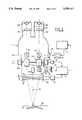
- FIG. 1shows an arrangement of the surgical microscope according to the invention mounted on a suitable multi-link supporting stand
- FIG. 2is a front elevation schematic representation of the surgical microscope of FIG. 1;
- FIG. 3is a side elevation view of the position-detecting system operating according to the laser-triangulation principle and disposed in the lower portion of the surgical microscope shown in FIGS. 1 and 2;
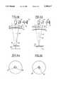
- FIGS. 4a and 4bshow various focusing positions
- FIGS. 5a and 5bshow the corresponding graphic displays on a TV-display or in a viewing beam path.
- FIG. 1shows an arrangement for the use of the surgical microscope 1 according to the invention for computer-supported stereotactic microsurgery.
- the surgical microscope 1is securely mounted on a special multi-link supporting stand 2 which enables the surgical microscope 1 to be manipulated in all six degrees of freedom.
- Most significant for the multi-link supporting stand 2 used hereis that the actual spatial coordinates as well as the orientation of the microscope 1 mounted thereon can always be detected by the built-in displacement and angle detectors.
- a computeroperates as a process-control unit 3 and determines the spatial coordinates and orientation of the surgical microscope from the supplied detector signals.
- the built-in displacement and angle detectorsare represented schematically by block 42 in FIG. 2.
- the process-control unit 3is mounted in the base part of the multi-link supporting stand 2.
- An image-processing unit 4is connected to the process-control unit 3 and graphically converts the signals of the position-detecting system to a TV-display 31 shown in FIG. 2. This TV-display can be integrated into the viewing beam path of the surgical microscope.
- the observed field of viewcan be displayed on a diagnostic monitor 5 via a corresponding camera output of the surgical microscope 1 and can, for example, be superposed with a diagnostic image reconstructed during the surgery after the coordinates and the position of the field of view are determined.
- This reconstructed diagnostic imagecan, alternatively, and as already mentioned, be displayed via the TV-display in the viewing beam path of the surgical microscope 1.
- the image-processing unit 4takes over the reconstruction of the diagnostic image to be displayed from the diagnostic data record prepared preoperatively. In this way, an on-line use of diagnostic data is possible as the surgeon performs the surgery.
- the head 6 of the patient lying on the operating table 8is fixed with a special stereotaxic frame 7 which, in turn, is fixedly connected to the operating table 8.
- This stereotaxic frame 7is also used as a localization aid during the development of a preoperative diagnostic record and therefore makes possible the correlation of this diagnostic data record with the observed field of view.
- FIG. 2shows a front elevation view of an embodiment of the surgical microscope according to the invention.
- the surgical microscope 1 of the inventionincludes a two-part primary objective comprising a converging lens 9 and a diverging lens 10 for the two stereoscopically separated viewing beam paths.
- the two primary objective lenses (9, 10)can be displaced relative to each other along the optical axis 18 for focusing.
- a zoom system (11a, 11b) for each of the two viewing beam pathsis provided for changing the magnification setting.
- Parallel lenses (12a, 12b) and ocular lenses (13a, 13b)are mounted in each of the two viewing beam paths.
- Detectors (15, 16)are provided for determining the actual optical system data and detect the actual setting of the zoom system (11a, 11b) and the primary objective (9, 10) on the respective displacement elements (34, 34a) corresponding thereto and transmit this setting to the computer of the process-control unit 3.
- a position-detecting systemwhich operates pursuant to the laser triangulation principle is mounted between the primary objective (9, 10) and the zoom system (11a, 11b).
- the laser beam generated by a laser diode(not shown in FIG. 2) is projected onto the object surface 19 via a deflecting mirror 17 and through the primary objective (9, 10).
- the laser light scattered by the object surface 19is coupled out of one of the viewing beam paths with the aid of out-coupling element 20.
- the out-coupled laser lightis imaged on a suitable position-resolving detector 23 via a filter 21 and a projection lens 22.
- the position-resolving detectorcan be realized, for example, by a CCD-line array, a CCD-surface array or position-sensitive detectors (PSD).
- the position-detecting system shown hereis built up on an optical basis and is not specific to the invention per se. Alternatives in the arrangement of the in-coupled and out-coupled beam paths are also possible or other known optical position-detecting systems are likewise possible which can be integrated into the optics of the surgical microscope.
- the actual position of the reflected laser beam on the position detector 23is graphically displayed on a TV-display 31 after the detector signals are evaluated in the computer of the process-control unit 3 and further processed in the image-processing unit 4.
- the desired position of the scattered laser beam on the position detector 23is likewise displayed on the TV-display 31.
- the scattered laser beamassumes the desired position when the plane 24 of the field of view and the marked object detail 19 lie in one plane.
- the two graphic markings of actual position and desired position of the scattered laser beammust be brought into overlapping alignment on the position detector 23 by focusing the surgical microscope 1.
- it is not essential to the invention as to how focusing takes placethat is, in addition to the focusing of the objective of variable focal length, a displacement of the complete surgical microscope 1 along the optical axis 18 is also possible when an objective of fixed focal length is used.
- the graphical display on the TV-display 31is reflected into at least one of the two viewing beam paths via an in-reflecting device.
- This in-reflection or in-coupling of the desired and actual positions of the laser beam on the position detector 23takes place via a projection lens 25, an in-coupling element 26 and a barrel lens 12b into the intermediate image plane 32 of the binocular tube.
- the observed field of view provided by the microscope and the graphical display of the desired and actual positions of the scattered laser beam on the position detector 23are superposed on each other for the viewer.
- the defined position determination of the marked object detail on the optical axis 18takes place only after said field of view and said positions have been brought into alignment by corresponding through-focusing of the surgical microscope 1.
- the detectors (15, 16) on the optical zoom system (11a, 11b) and the primary objective (9, 10)are read out and processed by the process-control unit 3.
- the process-control unit 3Together with the simultaneously obtained spatial and orientation coordinates of the surgical microscope 1 from the displacement and angle detectors (block 42) of the multi-link supporting stand, the defined position determination of the marked object detail or of the observed field of view is possible.
- FIG. 3A side elevation view of the lower portion of the surgical microscope of FIG. 2 is shown in FIG. 3.
- the laser beamis then guided by the deflecting mirror 17 via the primary objective (9, 10) onto the surface 19 of the object.
- the arrangement of the position-detecting system in accordance with the laser triangulation principleis not essential to the invention in this embodiment.
- a laser diode 28which emits in the infrared spectral range. This brings advantages for the detection of scattered laser rays since, with the aid of a wavelength-selective out-coupling element 20, the scattered laser beam can be separated from the viewing beam path in a defined manner.
- a filter 21is provided forward of the position detector 23 and transmits only for the laser wavelength used. By means of this filter 21, it is in addition ensured that no scattered light from the ambient reaches the position detector 23 which could produce incorrect information.
- FIGS. 4a, 4bVarious focusing states of such a system as well as the corresponding graphical displays on the TV-display or in the in-reflected intermediate image are shown in FIGS. 4a, 4b as well as in FIGS. 5a and 5b.
- marked object surface 19 and the plane 24 of the field of view of the surgical microscopeare not in one plane.
- the laser beamis projected via the deflecting mirror 17 along the optical axis 18 onto the object surface 19.
- the scattered laser beam 40is registered on the position detector 23 via primary objective (9, 10), out-coupling element 20, filter 21 and projection lens 22.
- the scattered laser beam 40still does not show the position which is required for the precise measurement of the plane of the field of view.
- FIG. 5aOne example of a graphical conversion of this state via the image-processing unit on a TV-display or the in-reflected intermediate image is shown in FIG. 5a.
- Open sighting cross lines 29mark the desired state in the center of the field of view for the position of the scattered laser beam on the position detector 23 when the marked object surface 19 and the plane 24 of the field of view of the surgical microscope are coincident.
- the current actual position of the scattered laser beam on the position detector 23is marked by the position of the cross 30 on the TV-display or in the in-reflected intermediate image.
- the surgeonnow brings the two marks into alignment by through-focusing the optical system in order to obtain a defined position of the marked object detail on the optical axis 18.
- This stateis shown in FIG. 4b as are the marks (29, 30) in FIG. 5b which were brought into alignment.
- the position of the plane 24 of the field of view relative to the surgical microscope 1is determined with the aid of the optical system data read out of the corresponding detectors (15, 16).
- the defined determination of the viewed object detail in the patient coordinate systemis then possible.
- the position of several known points in the patient coordinate systemis determined with the aid of the surgical microscope 1 according to the invention. With these measured points, the position and orientation of the patient in space can be determined.
- the correlation of the observed field of view with the corresponding diagnostic datais possible after an appropriate transformation of the coordinates is made.
Landscapes
- Physics & Mathematics (AREA)
- Health & Medical Sciences (AREA)
- General Physics & Mathematics (AREA)
- Surgery (AREA)
- Chemical & Material Sciences (AREA)
- Analytical Chemistry (AREA)
- Optics & Photonics (AREA)
- General Health & Medical Sciences (AREA)
- Engineering & Computer Science (AREA)
- Life Sciences & Earth Sciences (AREA)
- Nuclear Medicine, Radiotherapy & Molecular Imaging (AREA)
- Oral & Maxillofacial Surgery (AREA)
- Pathology (AREA)
- Multimedia (AREA)
- Biomedical Technology (AREA)
- Heart & Thoracic Surgery (AREA)
- Medical Informatics (AREA)
- Molecular Biology (AREA)
- Animal Behavior & Ethology (AREA)
- Public Health (AREA)
- Veterinary Medicine (AREA)
- Microscoopes, Condenser (AREA)
Abstract
Description
In conventional microsurgery conducted with the aid of a surgical microscope, problems often occur with respect of the interpretation of the field of view observed through the surgical microscope. The field of view is the instantaneously viewed anatomic situation. The task is then often presented to correlate diagnostic data obtained via various image-producing investigative methods (computer-tomography CT, nuclear magnetic resonance NMR and the like) to the instantaneous observed field of view in order to undertake a specific surgical step. The interpretation and analysis of the field of view provided by the microscope is therefore difficult and time consuming for the surgeon.
An effort to solve this difficulty is based on the use of stereotactic methods in order to make possible a rapid use of the diagnostic data during surgery. Thus, U.S. Pat. No. 4,722,056 discloses a surgical microscope and a method of operating the same wherein images from a preoperative diagnostic method can be superposed on the observed field of view with the aid of an in-reflecting device. The correlation between the surgical microscope and the patient, that is, the determination of the coordinates of the observed field of view is provided here by the determination of the surgical microscope spatial coordinates with the aid of an ultrasonic scanning system. From the spatial coordinates of the surgical microscope, a conclusion is drawn as to the position of the field of view in space from the particular actual optical system data. Here, it can be assumed that the optic detail of interest lies in the plane of the field of view.
This method of localizing the field of view and correlating the same to the corresponding diagnostic data does however have significant disadvantages. Thus, imaging through the optical system of the surgical microscope is always burdened with a certain depth of field which, for magnifications which are customary in neurosurgery, can be in the range of less than tenths of millimeter up to several centimeters. If an anatomic detail becomes of interest to the surgeon during the course of surgery, then the surgeon focuses the microscope on the corresponding location but must take into consideration a certain imprecision between the object detail of interest and the focus plane because of the above-mentioned depth of field, the surgeon's own possible accommodation as well as optical tolerances in the system. Such an arrangement permits no highly precise direct measurement of detail of the object of interest. A reliable target location with the aid of the surgical microscope is likewise not guaranteed. A further disadvantage of this arrangement is the complex configuration of the ultrasonic scanning system at the surgical microscope which hinders the surgeon during surgery.
A similar solution to this problem is disclosed in published German patent application 4,032,207. Here, the exact spatial position of the surgical microscope, which is supported by an articulated linkage mechanism, is determined via the detectors in this mechanism. These detectors detect movement directions and distances of the movable elements. The precise position of the observed field of view in space is computed by determining the coordinates of the surgical microscope from the detector signals as well as from the detected data of the optical system such as the instantaneous focusing state. The determination of the position of the field of view solely from the data of the optical system after successful focusing on the object detail of interest is here associated with the same inaccuracies which were described above. The depth of field problematic, physiological realization characteristics as well as optical tolerances in the system here too prevent a precise determination of position of the observed field of view and especially a direct measurement thereof.
It is an object of the invention to provide a surgical microscope as well as a method for operating the same which permit the observed field of view to be precisely detected with respect to its coordinates and therefore make possible the correlation with the corresponding diagnostic data from image-yielding diagnostic methods. The precision of the coordinate detection is intended to be dependent upon the resolution limit of the particular image-yielding diagnostic method. Furthermore, the essential components are integrated into the optics of the surgical microscope.
The method of the invention is for operating a surgical microscope arrangement for computer-supported stereotactic microsurgery. The arrangement includes a surgical stereomicroscope having an optical system with two viewing beam paths for viewing a detail of an object defining an object detail plane passing through the object detail. The method includes the steps of: continuously determining the spatial coordinates and the orientation of the surgical stereomicroscope and supply a first signal indicative thereof to a process control unit; continuously detecting the current position of the object plane via an optical position detection system and supplying a second signal indicative thereof to the process control unit; applying the output of the process control unit to an image-processing unit for converting the output into display signals graphically displaying the current position of the object detail plane on a TV-display as a first display; graphically displaying the current position of the plane of the field of view observed through the surgical stereomicroscope on the TV-display as a second display via the process-control unit and the image-processing unit; focusing or defocusing the optical system of the surgical stereomicroscope to bring the first and second displays into overlapping alignment with each other; determining the optical system data of the optical system utilizing detectors monitoring the optical system and supplying a third signal indicative thereof to the process control unit; determining the position of the object detail plane relative to the surgical stereomicroscope with the aid of the optical system data; and, determining the spatial coordinates of the object detail plane from the following: the coordinates of the object detail plane relative to the surgical stereomicroscope, the spatial coordinates of the surgical stereomicroscope and the orientation of the surgical stereomicroscope after a coordinate transformation.
An essential characteristic of the invention is that a selected and marked object detail is brought into superposition with the particular plane of the field of view via a sighting method. If this is ensured, then the relative position of the object detail forward of the surgical microscope is determined from the optical system data of the surgical microscope. In this connection, the knowledge of the precise spatial coordinates and the orientation of the surgical microscope is necessary. The arrangement of the surgical microscope of the invention on a multi-link stand is advantageous for this purpose. Suitable displacement and angle detectors in this multi-link stand enable the position and orientation of the surgical microscope to be precisely detected. When the precise spatial position of the surgical microscope is known, then a conclusion can be drawn as to the position of the observed object detail or of the observed field of view in the patient coordinate system from this precise spatial position together with the result of a previous calibration method. In such a calibration measurement, known points in the patient coordinate system can be measured via the described sighting method. These points in the patient coordinate system are likewise detected via the image-yielding diagnostic method. A diagnostic image corresponding to the position and magnitude of the detected field of view can be provided from the diagnostic data assembled prior to surgery. This diagnostic image can then be reflected into the viewing beam path via a corresponding in-reflecting device. In this way, a superposition of the diagnostic image and the observed field of view is possible. Alternatively, such a display can also take place on a separate diagnostic monitor. In this way, the computer-supported stereotactic use of the surgical microscope is ensured.
Such a sighting method is made possible in that markings are reflected into the viewing beam path which make clear the relative position of the plane of the field of view as well as the position of a laser beam projected onto an object detail. For this purpose, the precise position of the plane of the field of view of the surgical microscope is determined with the aid of a position-detecting system having an optics basis, for example according to the laser-triangulation principle. The position of a laser beam scattered from the surface of the object is evaluated for this purpose on a position-resolving detector. Each change in the spacing between object and microscope or in the focusing of the microscope leads to a lateral displacement of the imaged laser beam on the position-resolving detector. The actual position of the laser beam detected with the aid of a special process control as well as the desired position is displayed via an image-processing arrangement on a TV-display when there is coincidence of the plane of the field of view and the object detail and is reflected into the viewing beam path of the surgical microscope.
By focusing or defocusing the surgical microscope, an effort is made to bring these two marks so that they precisely overlap each other whereby a defined field of view marking (that is, the definite position of the object detail) is ensured. The focusing can take place via an intercept distance variation of the objective system used. However, it is also possible to displace the complete surgical microscope along the optical axis. Only after this sighting method, the precise position of the object detail marked in this manner is determined from the optical-system data. The optical-system data and especially the actual magnification of the magnification system and the adjusted focal length of the primary objective can be detected with suitable distance and/or angle detectors on the drive units for the particular setting. In this way, the relative position of the observed object detail to the surgical microscope is precisely defined. The precise position of the object detail in the patient coordinate system can then be determined together with the spatial coordinates of the surgical microscope and a necessary previous calibration on the patient.
An advantageous processing of the information determined in this manner is in the correlation of the detected field of view defined now with respect to position and orientation together with corresponding diagnostic images (CT, NMR, and the like). These diagnostic images can be superposed on the image section viewed while considering the actual surgical microscope-system data in that the diagnostic images are reflected into the viewing-beam path.
Furthermore, it has been shown to be advantageous to include in a reference measurement the mechanical tolerances of the magnification system and the mechanical tolerances of the focusing as well as adjusting errors of the optical system (such as those occurring during assembly of a surgical microscope of this kind) and to consider the same in the process control. During focusing of the optical system, the errors detected in the reference measurement are continuously considered when determining the coordinates of both the actual plane of the field of view and of marked object detail and are correspondingly corrected for graphical display.
It has likewise been shown advantageous to reflect-in the graphic marks between the binocular tube and the magnification changer.
The position-detecting system according to the laser-triangulation principle operates most advantageously in the non-visible spectral range such as in the near infrared. In this way, a laser with high capacity need not be used which would have been necessary in view of the high illumination intensity in the field of view of the surgical microscope in order to clearly localize the projected laser beam on the object. Furthermore, with an appropriately sensitive position detector, it is ensured that this detector only processes the information of the laser beam of interest and not false information caused by scattered light.
The invention will now be described with reference to the drawings wherein:
FIG. 1 shows an arrangement of the surgical microscope according to the invention mounted on a suitable multi-link supporting stand;
FIG. 2 is a front elevation schematic representation of the surgical microscope of FIG. 1;
FIG. 3 is a side elevation view of the position-detecting system operating according to the laser-triangulation principle and disposed in the lower portion of the surgical microscope shown in FIGS. 1 and 2;
FIGS. 4a and 4b show various focusing positions; and,
FIGS. 5a and 5b show the corresponding graphic displays on a TV-display or in a viewing beam path.
FIG. 1 shows an arrangement for the use of thesurgical microscope 1 according to the invention for computer-supported stereotactic microsurgery. Thesurgical microscope 1 is securely mounted on a special multi-link supporting stand 2 which enables thesurgical microscope 1 to be manipulated in all six degrees of freedom. Most significant for the multi-link supporting stand 2 used here is that the actual spatial coordinates as well as the orientation of themicroscope 1 mounted thereon can always be detected by the built-in displacement and angle detectors. A computer operates as a process-control unit 3 and determines the spatial coordinates and orientation of the surgical microscope from the supplied detector signals. The built-in displacement and angle detectors are represented schematically by block 42 in FIG. 2. The process-control unit 3 is mounted in the base part of the multi-link supporting stand 2. An image-processing unit 4 is connected to the process-control unit 3 and graphically converts the signals of the position-detecting system to a TV-display 31 shown in FIG. 2. This TV-display can be integrated into the viewing beam path of the surgical microscope.
The observed field of view can be displayed on adiagnostic monitor 5 via a corresponding camera output of thesurgical microscope 1 and can, for example, be superposed with a diagnostic image reconstructed during the surgery after the coordinates and the position of the field of view are determined. This reconstructed diagnostic image can, alternatively, and as already mentioned, be displayed via the TV-display in the viewing beam path of thesurgical microscope 1. The image-processing unit 4 takes over the reconstruction of the diagnostic image to be displayed from the diagnostic data record prepared preoperatively. In this way, an on-line use of diagnostic data is possible as the surgeon performs the surgery.
To ensure a reproducible position of the head of the patient during surgery, for example, during brain surgery, the head 6 of the patient lying on the operating table 8 is fixed with a special stereotaxic frame 7 which, in turn, is fixedly connected to the operating table 8. This stereotaxic frame 7 is also used as a localization aid during the development of a preoperative diagnostic record and therefore makes possible the correlation of this diagnostic data record with the observed field of view.
FIG. 2 shows a front elevation view of an embodiment of the surgical microscope according to the invention. In addition, the necessary evaluation units for the operation of such asurgical microscope 1 for stereotactic computer-supported microsurgery are also shown. Thesurgical microscope 1 of the invention includes a two-part primary objective comprising a converginglens 9 and a diverginglens 10 for the two stereoscopically separated viewing beam paths. The two primary objective lenses (9, 10) can be displaced relative to each other along theoptical axis 18 for focusing.
In addition, a zoom system (11a, 11b) for each of the two viewing beam paths is provided for changing the magnification setting. Parallel lenses (12a, 12b) and ocular lenses (13a, 13b) are mounted in each of the two viewing beam paths. Detectors (15, 16) are provided for determining the actual optical system data and detect the actual setting of the zoom system (11a, 11b) and the primary objective (9, 10) on the respective displacement elements (34, 34a) corresponding thereto and transmit this setting to the computer of the process-control unit 3.
A position-detecting system which operates pursuant to the laser triangulation principle is mounted between the primary objective (9, 10) and the zoom system (11a, 11b). The laser beam generated by a laser diode (not shown in FIG. 2) is projected onto theobject surface 19 via a deflectingmirror 17 and through the primary objective (9, 10). The laser light scattered by theobject surface 19 is coupled out of one of the viewing beam paths with the aid of out-coupling element 20. The out-coupled laser light is imaged on a suitable position-resolvingdetector 23 via afilter 21 and aprojection lens 22. The position-resolving detector can be realized, for example, by a CCD-line array, a CCD-surface array or position-sensitive detectors (PSD). The position-detecting system shown here is built up on an optical basis and is not specific to the invention per se. Alternatives in the arrangement of the in-coupled and out-coupled beam paths are also possible or other known optical position-detecting systems are likewise possible which can be integrated into the optics of the surgical microscope.
The actual position of the reflected laser beam on theposition detector 23 is graphically displayed on a TV-display 31 after the detector signals are evaluated in the computer of the process-control unit 3 and further processed in the image-processing unit 4. The desired position of the scattered laser beam on theposition detector 23 is likewise displayed on the TV-display 31. The scattered laser beam assumes the desired position when theplane 24 of the field of view and themarked object detail 19 lie in one plane. In order to now ensure a defined measurement of an object detail, the two graphic markings of actual position and desired position of the scattered laser beam must be brought into overlapping alignment on theposition detector 23 by focusing thesurgical microscope 1. Here, it is not essential to the invention as to how focusing takes place, that is, in addition to the focusing of the objective of variable focal length, a displacement of the completesurgical microscope 1 along theoptical axis 18 is also possible when an objective of fixed focal length is used.
In order to provide the surgeon with the assistance needed for focusing, the graphical display on the TV-display 31 is reflected into at least one of the two viewing beam paths via an in-reflecting device. This in-reflection or in-coupling of the desired and actual positions of the laser beam on theposition detector 23 takes place via aprojection lens 25, an in-coupling element 26 and a barrel lens 12b into theintermediate image plane 32 of the binocular tube. Here, the observed field of view provided by the microscope and the graphical display of the desired and actual positions of the scattered laser beam on theposition detector 23 are superposed on each other for the viewer. The defined position determination of the marked object detail on theoptical axis 18 takes place only after said field of view and said positions have been brought into alignment by corresponding through-focusing of thesurgical microscope 1. For this purpose, the detectors (15, 16) on the optical zoom system (11a, 11b) and the primary objective (9, 10) are read out and processed by the process-control unit 3. Together with the simultaneously obtained spatial and orientation coordinates of thesurgical microscope 1 from the displacement and angle detectors (block 42) of the multi-link supporting stand, the defined position determination of the marked object detail or of the observed field of view is possible.
An increase in the precision of evaluation is obtained in that, during assembly of a surgical microscope of this kind in a reference measurement, the optical and mechanical deviations of the system are detected during through-focusing and are stored in order to be applied during the actual measurement for evaluation.
It is in addition possible to detect the observed field of view with a suitable camera and display the same on a diagnostic monitor via a second out-coupling element 33 in the second viewing beam path. After determining the coordinates of the observed field of view, a corresponding previously developed diagnostic image can be superposed on the diagnostic monitor. It is likewise possible, with the aid of image-processing unit 4 and TV-display 31, to superpose in the viewing beam path such a diagnostic image on the field of view determined with respect to coordinates.
A side elevation view of the lower portion of the surgical microscope of FIG. 2 is shown in FIG. 3. Alaser diode 28, which is controlled via the computer of the process-control unit 3, projects a laser beam onto a deflectingmirror 17 via two lenses (27a, 27b) which operate to expand and form the beam. The laser beam is then guided by the deflectingmirror 17 via the primary objective (9, 10) onto thesurface 19 of the object. The arrangement of the position-detecting system in accordance with the laser triangulation principle is not essential to the invention in this embodiment.
In the embodiment shown in FIGS. 2 and 3, alaser diode 28 is used which emits in the infrared spectral range. This brings advantages for the detection of scattered laser rays since, with the aid of a wavelength-selective out-coupling element 20, the scattered laser beam can be separated from the viewing beam path in a defined manner. Afilter 21 is provided forward of theposition detector 23 and transmits only for the laser wavelength used. By means of thisfilter 21, it is in addition ensured that no scattered light from the ambient reaches theposition detector 23 which could produce incorrect information.
Various focusing states of such a system as well as the corresponding graphical displays on the TV-display or in the in-reflected intermediate image are shown in FIGS. 4a, 4b as well as in FIGS. 5a and 5b. In the case of FIG. 4a, markedobject surface 19 and theplane 24 of the field of view of the surgical microscope are not in one plane. The laser beam is projected via the deflectingmirror 17 along theoptical axis 18 onto theobject surface 19. The scattered laser beam 40 is registered on theposition detector 23 via primary objective (9, 10), out-coupling element 20,filter 21 andprojection lens 22. The scattered laser beam 40 still does not show the position which is required for the precise measurement of the plane of the field of view.
One example of a graphical conversion of this state via the image-processing unit on a TV-display or the in-reflected intermediate image is shown in FIG. 5a. Opensighting cross lines 29 mark the desired state in the center of the field of view for the position of the scattered laser beam on theposition detector 23 when themarked object surface 19 and theplane 24 of the field of view of the surgical microscope are coincident. The current actual position of the scattered laser beam on theposition detector 23 is marked by the position of thecross 30 on the TV-display or in the in-reflected intermediate image. The surgeon now brings the two marks into alignment by through-focusing the optical system in order to obtain a defined position of the marked object detail on theoptical axis 18. This state is shown in FIG. 4b as are the marks (29, 30) in FIG. 5b which were brought into alignment. As soon as coincidence is reached, the position of theplane 24 of the field of view relative to thesurgical microscope 1 is determined with the aid of the optical system data read out of the corresponding detectors (15, 16).
Together with the determined spatial and orientation coordinates of thesurgical microscope 1 and a previous calibration measurement, the defined determination of the viewed object detail in the patient coordinate system is then possible. During the previously carried out calibration measurement, the position of several known points in the patient coordinate system is determined with the aid of thesurgical microscope 1 according to the invention. With these measured points, the position and orientation of the patient in space can be determined. Together with the field of view coordinates determined subsequently via the method pursuant to the invention, the correlation of the observed field of view with the corresponding diagnostic data is possible after an appropriate transformation of the coordinates is made.
As an alternative to the manual through-focusing of the surgical microscope, it is possible to carry out the described sighting method in the form of an automatic focusing with the process-control unit 3 taking over the through-focusing via a corresponding drive.
It is understood that the foregoing description is that of the preferred embodiments of the invention and that various changes and modifications may be made thereto without departing from the spirit and scope of the invention as defined in the appended claims.
Claims (14)
1. A surgical microscope arrangement for computer-supported stereotactic microsurgery, the arrangement comprising:
a surgical stereomicroscope having an optical system defining two viewing beam paths for viewing an object defining an object plane;
detector means for monitoring said optical system to obtain a first signal indicative of the setting of said optical system;
an optical position detection system integrated into said optical system for detecting the position of said object plane and for supplying a second signal indicative of said position;
process control means for processing said first and second signals and supplying an output signal; and,
an image-processing unit for converting the output signal of said process control means into display signals for providing a graphic display.
2. The surgical microscope arrangement of claim 1, said optical position detection system being configured to operate pursuant to the laser triangulation principle.
3. The surgical microscope arrangement of claim 1, said image-processing unit including a TV-display for providing a graphic display of said display signals.
4. The surgical microscope arrangement of claim 3, further comprising an in-reflecting device for coupling said graphic display into one of said viewing beam paths, said in-reflecting device including a projection optic for receiving and transmitting said graphic display from said TV-display; and, an in-coupling element mounted downstream of said projection optic and being disposed in said one beam path for coupling said graphic display into said one beam path.
5. The surgical microscope arrangement of claim 1, said optical system including magnification means mounted in said viewing beam paths and an objective arranged downstream of said magnification means; and, said optical position detection system being mounted between said magnification means and said objective.
6. The surgical microscope arrangement of claim 5, said optical position detection system comprising:
a laser light source for generating a laser light;
optical means for receiving said light and forming a laser light beam therefrom; and,
a deflecting element mounted between said magnification means and said objective for directing said laser light beam through said objective to said object.
7. The surgical microscope arrangement of claim 5, said optical position detecting system comprising laser beam means for directing a laser light beam through said objective onto said object where the light of the laser light beam backscatters from said object and enters said viewing beam paths; out-coupling means arranged in one of said viewing beam paths for coupling the backscattered light out of said one viewing beam path; imaging optic means for receiving and transmitting the backscattered light; and, a position-resolving detector for receiving the light transmitted by said imaging optic means.
8. The surgical microscope arrangement of claim 1, further comprising: a multi-link stand and said stereomicroscope being mounted on said multi-link stand; and, sensor means for supplying signals indicative of the actual spatial coordinates and orientation of said surgical stereomicroscope.
9. A method of operating a surgical microscope arrangement for computer-supported stereotactic microsurgery, the arrangement including a surgical stereomicroscope having an optical system with two viewing beam paths for viewing a detail of an object defining an object detail plane passing through said object detail, and the method comprising the steps of:
continuously determining the spatial coordinates and the orientation of said surgical stereomicroscope and supplying a first signal indicative thereof to a process control unit having an output;
continuously detecting the current position of said object plane via an optical position detection system and supplying a second signal indicative thereof to said process control unit;
applying the output of said process control unit to an image-processing unit for converting the output into display signals graphically displaying said current position of said object detail plane on a TV-display as a first display;
graphically displaying the current position of the plane of the field of view observed through the surgical stereomicroscope on said TV-display as a second display via said process-control unit and said image-processing unit;
focusing or defocusing said optical system of said surgical stereomicroscope to bring said first and second displays into overlapping alignment with each other;
determining the optical system data of said optical system utilizing detectors monitoring said optical system and supplying a third signal indicative thereof to said process control unit;
determining the position of said object detail plane relative to said surgical stereomicroscope with the aid of said optical system data; and,
determining the spatial coordinates of said object detail plane from the following: the coordinates of said object detail plane relative to said surgical stereomicroscope, said spatial coordinates of said surgical stereomicroscope and said orientation of said surgical stereomicroscope after a coordinate transformation.
10. The method of claim 9, said first and second graphic displays being reflected into at least one of said viewing beam paths.
11. The method of claim 9, further comprising the step of superposing an image from a preoperative diagnostic method on said field of view after determining the coordinates of the object detail in space and considering the magnification of said optical system; and, said image having coordinates corresponding to said coordinates of said object detail.
12. The method of claim 9, wherein the graphic display of the position of the image plane takes place in the center of the field of view of the image section being viewed.
13. The method of claim 9, further comprising the steps of: conducting a reference measurement to detect optical and mechanical deviations of the optical system while through focusing; storing said deviations and considering said deviations to correct the instantaneously detected measured values.
14. The method of claim 9, wherein said focusing or defocusing of said optical system takes place automatically via said process control unit.
Priority Applications (2)
| Application Number | Priority Date | Filing Date | Title |
|---|---|---|---|
| US08/321,309US5513005A (en) | 1991-10-18 | 1994-10-11 | Method of operating a surgical microscope arrangement for computer-supported stereotactic microsurgery on a patient |
| US08/670,772US5657128A (en) | 1991-10-18 | 1996-06-24 | Surgical microscope for conducting computer-supported stereotactic microsurgery and a method for operating the same |
Applications Claiming Priority (2)
| Application Number | Priority Date | Filing Date | Title |
|---|---|---|---|
| DE4134481ADE4134481C2 (en) | 1991-10-18 | 1991-10-18 | Surgical microscope for computer-aided, stereotactic microsurgery |
| DE4134481 | 1991-10-18 |
Related Child Applications (1)
| Application Number | Title | Priority Date | Filing Date |
|---|---|---|---|
| US08/321,309ContinuationUS5513005A (en) | 1991-10-18 | 1994-10-11 | Method of operating a surgical microscope arrangement for computer-supported stereotactic microsurgery on a patient |
Publications (1)
| Publication Number | Publication Date |
|---|---|
| US5359417Atrue US5359417A (en) | 1994-10-25 |
Family
ID=6442949
Family Applications (3)
| Application Number | Title | Priority Date | Filing Date |
|---|---|---|---|
| US07/961,339Expired - LifetimeUS5359417A (en) | 1991-10-18 | 1992-10-15 | Surgical microscope for conducting computer-supported stereotactic microsurgery and a method for operating the same |
| US08/321,309Expired - LifetimeUS5513005A (en) | 1991-10-18 | 1994-10-11 | Method of operating a surgical microscope arrangement for computer-supported stereotactic microsurgery on a patient |
| US08/670,772Expired - LifetimeUS5657128A (en) | 1991-10-18 | 1996-06-24 | Surgical microscope for conducting computer-supported stereotactic microsurgery and a method for operating the same |
Family Applications After (2)
| Application Number | Title | Priority Date | Filing Date |
|---|---|---|---|
| US08/321,309Expired - LifetimeUS5513005A (en) | 1991-10-18 | 1994-10-11 | Method of operating a surgical microscope arrangement for computer-supported stereotactic microsurgery on a patient |
| US08/670,772Expired - LifetimeUS5657128A (en) | 1991-10-18 | 1996-06-24 | Surgical microscope for conducting computer-supported stereotactic microsurgery and a method for operating the same |
Country Status (5)
| Country | Link |
|---|---|
| US (3) | US5359417A (en) |
| JP (1) | JP3269578B2 (en) |
| CH (1) | CH684291A5 (en) |
| DE (1) | DE4134481C2 (en) |
| FR (1) | FR2682778B1 (en) |
Cited By (115)
| Publication number | Priority date | Publication date | Assignee | Title |
|---|---|---|---|---|
| US5493109A (en)* | 1994-08-18 | 1996-02-20 | Carl Zeiss, Inc. | Optical coherence tomography assisted ophthalmologic surgical microscope |
| US5549472A (en)* | 1995-06-02 | 1996-08-27 | Rollins Environmental Services, Inc. | Control of protective layer thickness in kilns by utilizing two laser beams |
| WO1997031581A1 (en)* | 1996-02-27 | 1997-09-04 | Institute Of Systems Science | Curved surgical instruments and method of mapping a curved path for stereotactic surgery |
| US5731910A (en)* | 1993-12-24 | 1998-03-24 | Carl Zeiss Jena Gmbh | Optical system with variable image scale |
| US5795294A (en)* | 1994-05-21 | 1998-08-18 | Carl-Zeiss-Stiftung | Procedure for the correlation of different coordinate systems in computer-supported, stereotactic surgery |
| US5841149A (en)* | 1994-04-11 | 1998-11-24 | Leica Mikroskopie Systeme Ag | Method of determining the distance of a feature on an object from a microscope, and a device for carrying out the method |
| US5871445A (en) | 1993-04-26 | 1999-02-16 | St. Louis University | System for indicating the position of a surgical probe within a head on an image of the head |
| US5943914A (en)* | 1997-03-27 | 1999-08-31 | Sandia Corporation | Master-slave micromanipulator apparatus |
| US5985085A (en)* | 1997-10-01 | 1999-11-16 | Arcturus Engineering, Inc. | Method of manufacturing consumable for laser capture microdissection |
| US6004314A (en)* | 1994-08-18 | 1999-12-21 | Carl Zeiss, Inc. | Optical coherence tomography assisted surgical apparatus |
| US6146390A (en) | 1992-04-21 | 2000-11-14 | Sofamor Danek Holdings, Inc. | Apparatus and method for photogrammetric surgical localization |
| US6167145A (en) | 1996-03-29 | 2000-12-26 | Surgical Navigation Technologies, Inc. | Bone navigation system |
| US6184973B1 (en) | 1997-02-07 | 2001-02-06 | Arcturus Engineering, Inc. | Laser capture microdissection pressure plate and transfer arm |
| US6226418B1 (en) | 1997-11-07 | 2001-05-01 | Washington University | Rapid convolution based large deformation image matching via landmark and volume imagery |
| US6235038B1 (en) | 1999-10-28 | 2001-05-22 | Medtronic Surgical Navigation Technologies | System for translation of electromagnetic and optical localization systems |
| US6236875B1 (en) | 1994-10-07 | 2001-05-22 | Surgical Navigation Technologies | Surgical navigation systems including reference and localization frames |
| US6294774B1 (en)* | 1998-11-16 | 2001-09-25 | Jeol Ltd. | Scanning probe microscope having graphical information |
| US6347240B1 (en) | 1990-10-19 | 2002-02-12 | St. Louis University | System and method for use in displaying images of a body part |
| US6381485B1 (en) | 1999-10-28 | 2002-04-30 | Surgical Navigation Technologies, Inc. | Registration of human anatomy integrated for electromagnetic localization |
| US6379302B1 (en) | 1999-10-28 | 2002-04-30 | Surgical Navigation Technologies Inc. | Navigation information overlay onto ultrasound imagery |
| US6408107B1 (en) | 1996-07-10 | 2002-06-18 | Michael I. Miller | Rapid convolution based large deformation image matching via landmark and volume imagery |
| US20020120424A1 (en)* | 2001-01-03 | 2002-08-29 | Christoph Hauger | Method and apparatus for fixing a location |
| US6466432B1 (en)* | 1999-07-12 | 2002-10-15 | Frank Beger | Instrument and service unit for a surgical operating area |
| US6470578B1 (en)* | 1999-09-28 | 2002-10-29 | P&G Development Group, Inc. | Method and apparatus for indicating a pattern of intersection using a light column |
| US6474341B1 (en) | 1999-10-28 | 2002-11-05 | Surgical Navigation Technologies, Inc. | Surgical communication and power system |
| US6483948B1 (en)* | 1994-12-23 | 2002-11-19 | Leica Ag | Microscope, in particular a stereomicroscope, and a method of superimposing two images |
| US6495195B2 (en) | 1997-02-14 | 2002-12-17 | Arcturus Engineering, Inc. | Broadband absorbing film for laser capture microdissection |
| US20030011677A1 (en)* | 2001-05-29 | 2003-01-16 | Leica Microsystems Ag | Method for measuring the separation of extended objects in conjunction with an optical observation system and microscope for carrying out the same |
| WO2002039877A3 (en)* | 2000-11-17 | 2003-02-06 | Univ Oregon Health & Science | Stereotactic wands, endoscopes, and methods using such wands and endoscopes |
| US6528248B2 (en) | 1999-04-29 | 2003-03-04 | Arcturus Engineering, Inc. | Processing technology for LCM samples |
| US6535756B1 (en) | 2000-04-07 | 2003-03-18 | Surgical Navigation Technologies, Inc. | Trajectory storage apparatus and method for surgical navigation system |
| US20030142398A1 (en)* | 2000-03-08 | 2003-07-31 | Leblans Marc Jan Rene | Microscope suitable for high-throughput screening having an autofocusing apparatus |
| US6633686B1 (en) | 1998-11-05 | 2003-10-14 | Washington University | Method and apparatus for image registration using large deformation diffeomorphisms on a sphere |
| US6639789B2 (en) | 2000-07-12 | 2003-10-28 | Karl Storz Gmbh & Co. Kg | Instrument and service unit for a surgical operating area |
| US6690470B1 (en) | 1999-11-04 | 2004-02-10 | Arcturus Engineering, Inc. | Automated laser capture microdissection |
| US6725080B2 (en) | 2000-03-01 | 2004-04-20 | Surgical Navigation Technologies, Inc. | Multiple cannula image guided tool for image guided procedures |
| WO2004040234A3 (en)* | 2002-11-01 | 2004-08-12 | Werth Messtechnik Gmbh | Arrangement for measuring the geometry or structure of an object |
| EP1537830A1 (en)* | 2003-12-05 | 2005-06-08 | Möller-Wedel GmbH | Method and device for viewing an object with a microscope |
| US6978166B2 (en) | 1994-10-07 | 2005-12-20 | Saint Louis University | System for use in displaying images of a body part |
| US20050280891A1 (en)* | 2004-06-18 | 2005-12-22 | Bogle Alan W | Projection microscope |
| US7075640B2 (en) | 1997-10-01 | 2006-07-11 | Arcturus Bioscience, Inc. | Consumable for laser capture microdissection |
| US7085400B1 (en) | 2000-06-14 | 2006-08-01 | Surgical Navigation Technologies, Inc. | System and method for image based sensor calibration |
| US7217276B2 (en) | 1999-04-20 | 2007-05-15 | Surgical Navigational Technologies, Inc. | Instrument guidance method and system for image guided surgery |
| US7313430B2 (en) | 2003-08-28 | 2007-12-25 | Medtronic Navigation, Inc. | Method and apparatus for performing stereotactic surgery |
| US7366562B2 (en) | 2003-10-17 | 2008-04-29 | Medtronic Navigation, Inc. | Method and apparatus for surgical navigation |
| US20080204864A1 (en)* | 2007-02-27 | 2008-08-28 | Leica Microsystems (Schweiz) Ag | Microscope Device With Position Sensing |
| US7473401B1 (en) | 1997-12-04 | 2009-01-06 | Mds Analytical Technologies (Us) Inc. | Fluidic extraction of microdissected samples |
| US7542791B2 (en) | 2003-01-30 | 2009-06-02 | Medtronic Navigation, Inc. | Method and apparatus for preplanning a surgical procedure |
| US7567834B2 (en) | 2004-05-03 | 2009-07-28 | Medtronic Navigation, Inc. | Method and apparatus for implantation between two vertebral bodies |
| US7570791B2 (en) | 2003-04-25 | 2009-08-04 | Medtronic Navigation, Inc. | Method and apparatus for performing 2D to 3D registration |
| US7599730B2 (en) | 2002-11-19 | 2009-10-06 | Medtronic Navigation, Inc. | Navigation system for cardiac therapies |
| US20090257065A1 (en)* | 2008-03-19 | 2009-10-15 | Carl Zeiss Surgical Gmbh | Surgical microscopy system having an optical coherence tomography facility |
| US7606613B2 (en) | 1999-03-23 | 2009-10-20 | Medtronic Navigation, Inc. | Navigational guidance via computer-assisted fluoroscopic imaging |
| US7630753B2 (en) | 2002-02-28 | 2009-12-08 | Medtronic Navigation, Inc. | Method and apparatus for perspective inversion |
| US7636595B2 (en) | 2004-10-28 | 2009-12-22 | Medtronic Navigation, Inc. | Method and apparatus for calibrating non-linear instruments |
| US7660623B2 (en) | 2003-01-30 | 2010-02-09 | Medtronic Navigation, Inc. | Six degree of freedom alignment display for medical procedures |
| US7697972B2 (en) | 2002-11-19 | 2010-04-13 | Medtronic Navigation, Inc. | Navigation system for cardiac therapies |
| US7763035B2 (en) | 1997-12-12 | 2010-07-27 | Medtronic Navigation, Inc. | Image guided spinal surgery guide, system and method for use thereof |
| US7797032B2 (en) | 1999-10-28 | 2010-09-14 | Medtronic Navigation, Inc. | Method and system for navigating a catheter probe in the presence of field-influencing objects |
| US7835778B2 (en) | 2003-10-16 | 2010-11-16 | Medtronic Navigation, Inc. | Method and apparatus for surgical navigation of a multiple piece construct for implantation |
| US7835784B2 (en) | 2005-09-21 | 2010-11-16 | Medtronic Navigation, Inc. | Method and apparatus for positioning a reference frame |
| US7840253B2 (en) | 2003-10-17 | 2010-11-23 | Medtronic Navigation, Inc. | Method and apparatus for surgical navigation |
| USRE42194E1 (en) | 1997-09-24 | 2011-03-01 | Medtronic Navigation, Inc. | Percutaneous registration apparatus and method for use in computer-assisted surgical navigation |
| US7998062B2 (en) | 2004-03-29 | 2011-08-16 | Superdimension, Ltd. | Endoscope structures and techniques for navigating to a target in branched structure |
| US8057407B2 (en) | 1999-10-28 | 2011-11-15 | Medtronic Navigation, Inc. | Surgical sensor |
| US8112292B2 (en) | 2006-04-21 | 2012-02-07 | Medtronic Navigation, Inc. | Method and apparatus for optimizing a therapy |
| USRE43328E1 (en) | 1997-11-20 | 2012-04-24 | Medtronic Navigation, Inc | Image guided awl/tap/screwdriver |
| US8165658B2 (en) | 2008-09-26 | 2012-04-24 | Medtronic, Inc. | Method and apparatus for positioning a guide relative to a base |
| US8175681B2 (en) | 2008-12-16 | 2012-05-08 | Medtronic Navigation Inc. | Combination of electromagnetic and electropotential localization |
| US8200314B2 (en) | 1992-08-14 | 2012-06-12 | British Telecommunications Public Limited Company | Surgical navigation |
| US20120187097A1 (en)* | 2011-01-25 | 2012-07-26 | Wu Jang-Yie | Laser engraver capable of automatic defocusing |
| US8239001B2 (en) | 2003-10-17 | 2012-08-07 | Medtronic Navigation, Inc. | Method and apparatus for surgical navigation |
| USRE43952E1 (en) | 1989-10-05 | 2013-01-29 | Medtronic Navigation, Inc. | Interactive system for local intervention inside a non-homogeneous structure |
| US8452068B2 (en) | 2008-06-06 | 2013-05-28 | Covidien Lp | Hybrid registration method |
| US8473026B2 (en) | 1994-09-15 | 2013-06-25 | Ge Medical Systems Global Technology Company | System for monitoring a position of a medical instrument with respect to a patient's body |
| US8473032B2 (en) | 2008-06-03 | 2013-06-25 | Superdimension, Ltd. | Feature-based registration method |
| US8494613B2 (en) | 2009-08-31 | 2013-07-23 | Medtronic, Inc. | Combination localization system |
| US8494614B2 (en) | 2009-08-31 | 2013-07-23 | Regents Of The University Of Minnesota | Combination localization system |
| US8611984B2 (en) | 2009-04-08 | 2013-12-17 | Covidien Lp | Locatable catheter |
| US8644907B2 (en) | 1999-10-28 | 2014-02-04 | Medtronic Navigaton, Inc. | Method and apparatus for surgical navigation |
| US8660635B2 (en) | 2006-09-29 | 2014-02-25 | Medtronic, Inc. | Method and apparatus for optimizing a computer assisted surgical procedure |
| US8663088B2 (en) | 2003-09-15 | 2014-03-04 | Covidien Lp | System of accessories for use with bronchoscopes |
| US8715955B2 (en) | 2004-09-09 | 2014-05-06 | Life Technologies Corporation | Laser microdissection apparatus and method |
| US8722357B2 (en) | 2001-11-05 | 2014-05-13 | Life Technologies Corporation | Automated microdissection instrument |
| US8768437B2 (en) | 1998-08-20 | 2014-07-01 | Sofamor Danek Holdings, Inc. | Fluoroscopic image guided surgery system with intraoperative registration |
| US8764725B2 (en) | 2004-02-09 | 2014-07-01 | Covidien Lp | Directional anchoring mechanism, method and applications thereof |
| US8838199B2 (en) | 2002-04-04 | 2014-09-16 | Medtronic Navigation, Inc. | Method and apparatus for virtual digital subtraction angiography |
| US8905920B2 (en) | 2007-09-27 | 2014-12-09 | Covidien Lp | Bronchoscope adapter and method |
| US8932207B2 (en) | 2008-07-10 | 2015-01-13 | Covidien Lp | Integrated multi-functional endoscopic tool |
| US9055881B2 (en) | 2004-04-26 | 2015-06-16 | Super Dimension Ltd. | System and method for image-based alignment of an endoscope |
| US9168102B2 (en) | 2006-01-18 | 2015-10-27 | Medtronic Navigation, Inc. | Method and apparatus for providing a container to a sterile environment |
| EP3008505A1 (en)* | 2013-06-14 | 2016-04-20 | William Tanner | Optical subject-positioning aid for a microscope |
| US9575140B2 (en) | 2008-04-03 | 2017-02-21 | Covidien Lp | Magnetic interference detection system and method |
| US9662010B2 (en) | 2014-09-19 | 2017-05-30 | Carl Zeiss Meditec Ag | Optical system, comprising a microscopy system and an OCT system |
| US9675424B2 (en) | 2001-06-04 | 2017-06-13 | Surgical Navigation Technologies, Inc. | Method for calibrating a navigation system |
| EP3130137A4 (en)* | 2014-03-13 | 2017-10-18 | Richard Awdeh | Methods and systems for registration using a microscope insert |
| US10073515B2 (en) | 2013-09-18 | 2018-09-11 | Nanophthalmos, Llc | Surgical navigation system and method |
| US10156501B2 (en) | 2001-11-05 | 2018-12-18 | Life Technologies Corporation | Automated microdissection instrument for determining a location of a laser beam projection on a worksurface area |
| US10254528B2 (en) | 2014-03-13 | 2019-04-09 | Nanophthalmos, Llc | Microscope insert |
| US10418705B2 (en) | 2016-10-28 | 2019-09-17 | Covidien Lp | Electromagnetic navigation antenna assembly and electromagnetic navigation system including the same |
| US10426555B2 (en) | 2015-06-03 | 2019-10-01 | Covidien Lp | Medical instrument with sensor for use in a system and method for electromagnetic navigation |
| US10446931B2 (en) | 2016-10-28 | 2019-10-15 | Covidien Lp | Electromagnetic navigation antenna assembly and electromagnetic navigation system including the same |
| US10478254B2 (en) | 2016-05-16 | 2019-11-19 | Covidien Lp | System and method to access lung tissue |
| US10517505B2 (en) | 2016-10-28 | 2019-12-31 | Covidien Lp | Systems, methods, and computer-readable media for optimizing an electromagnetic navigation system |
| US10582834B2 (en) | 2010-06-15 | 2020-03-10 | Covidien Lp | Locatable expandable working channel and method |
| US10615500B2 (en) | 2016-10-28 | 2020-04-07 | Covidien Lp | System and method for designing electromagnetic navigation antenna assemblies |
| US10638952B2 (en) | 2016-10-28 | 2020-05-05 | Covidien Lp | Methods, systems, and computer-readable media for calibrating an electromagnetic navigation system |
| US10722311B2 (en) | 2016-10-28 | 2020-07-28 | Covidien Lp | System and method for identifying a location and/or an orientation of an electromagnetic sensor based on a map |
| US10751126B2 (en) | 2016-10-28 | 2020-08-25 | Covidien Lp | System and method for generating a map for electromagnetic navigation |
| US10792106B2 (en) | 2016-10-28 | 2020-10-06 | Covidien Lp | System for calibrating an electromagnetic navigation system |
| US10952593B2 (en) | 2014-06-10 | 2021-03-23 | Covidien Lp | Bronchoscope adapter |
| US11006914B2 (en) | 2015-10-28 | 2021-05-18 | Medtronic Navigation, Inc. | Apparatus and method for maintaining image quality while minimizing x-ray dosage of a patient |
| US11219489B2 (en) | 2017-10-31 | 2022-01-11 | Covidien Lp | Devices and systems for providing sensors in parallel with medical tools |
| US11331150B2 (en) | 1999-10-28 | 2022-05-17 | Medtronic Navigation, Inc. | Method and apparatus for surgical navigation |
| US12089902B2 (en) | 2019-07-30 | 2024-09-17 | Coviden Lp | Cone beam and 3D fluoroscope lung navigation |
Families Citing this family (44)
| Publication number | Priority date | Publication date | Assignee | Title |
|---|---|---|---|---|
| EP0488987B1 (en)* | 1990-11-26 | 1996-01-31 | Michael Dr. Truppe | Method for representing moving bodies |
| US5823958A (en)* | 1990-11-26 | 1998-10-20 | Truppe; Michael | System and method for displaying a structural data image in real-time correlation with moveable body |
| US5442443A (en)* | 1993-04-08 | 1995-08-15 | Polaroid Corporation | Stereoscopic photon tunneling microscope |
| DE4416178B4 (en)* | 1993-05-07 | 2007-11-08 | Olympus Optical Co., Ltd. | Surgical microscope |
| FR2709657B1 (en)* | 1993-09-07 | 1995-12-01 | Deemed Int Sa | Optical designation device, in particular for microsurgery operation. |
| DE29522307U1 (en)* | 1994-03-24 | 2002-01-31 | Koninklijke Philips Electronics N.V., Eindhoven | surgical microscope |
| DE4412605B4 (en)* | 1994-04-13 | 2005-10-20 | Zeiss Carl | Method for operating a stereotactic adapter |
| US6351659B1 (en) | 1995-09-28 | 2002-02-26 | Brainlab Med. Computersysteme Gmbh | Neuro-navigation system |
| DE19639615C5 (en)* | 1996-09-26 | 2008-11-06 | Brainlab Ag | Reflector referencing system for surgical and medical instruments |
| DE19640907B4 (en)* | 1995-10-12 | 2005-09-22 | Carl Zeiss | Surgical microscope with integrated surgical navigation system |
| US6081370A (en)* | 1996-06-03 | 2000-06-27 | Leica Mikroskopie Systeme Ag | Determining the position of a moving object |
| US5795295A (en)* | 1996-06-25 | 1998-08-18 | Carl Zeiss, Inc. | OCT-assisted surgical microscope with multi-coordinate manipulator |
| GB9623911D0 (en)* | 1996-11-18 | 1997-01-08 | Armstrong Healthcare Ltd | Improvements in or relating to an orientation detector arrangement |
| DE19751781C2 (en)* | 1996-11-22 | 2002-02-14 | Leica Mikroskopie Systeme Ag H | Microscope with position monitoring |
| DE19731301C2 (en)* | 1997-07-13 | 2001-05-10 | Smi Senso Motoric Instr Gmbh | Device for controlling a microscope by means of gaze direction analysis |
| JPH1172717A (en)* | 1997-08-29 | 1999-03-16 | Nikon Corp | Microscope digital photography system |
| US5999837A (en)* | 1997-09-26 | 1999-12-07 | Picker International, Inc. | Localizing and orienting probe for view devices |
| US6081336A (en)* | 1997-09-26 | 2000-06-27 | Picker International, Inc. | Microscope calibrator |
| US6773430B2 (en) | 1999-08-09 | 2004-08-10 | Visx, Inc. | Motion detector for eye ablative laser delivery systems |
| DE10048546A1 (en)* | 2000-09-30 | 2002-04-11 | Zeiss Carl | surgical microscope |
| DE10111824B4 (en)* | 2001-03-13 | 2017-04-06 | Leica Microsystems Cms Gmbh | Method for adjusting a microscope and microscope with means for adjusting the light beam |
| DE10243852B4 (en)* | 2002-09-20 | 2006-01-26 | Carl Zeiss | Microscopy system and microscopy method |
| DE10335644B9 (en)* | 2003-08-04 | 2006-06-01 | Carl Zeiss | microscopy system |
| US8339447B2 (en)* | 2004-10-21 | 2012-12-25 | Truevision Systems, Inc. | Stereoscopic electronic microscope workstation |
| EP1846729A1 (en)* | 2004-12-16 | 2007-10-24 | Werth Messtechnik GmbH | Coordinate measuring device and method for measuring with a coordinate measuring device |
| US8358330B2 (en)* | 2005-10-21 | 2013-01-22 | True Vision Systems, Inc. | Stereoscopic electronic microscope workstation |
| US20070188603A1 (en)* | 2005-10-21 | 2007-08-16 | Riederer Thomas P | Stereoscopic display cart and system |
| DE102005050918A1 (en)* | 2005-10-24 | 2007-01-11 | Siemens Ag | Apparatus for monitoring microsurgery especially neurosurgery using an operation microscope |
| US9168173B2 (en) | 2008-04-04 | 2015-10-27 | Truevision Systems, Inc. | Apparatus and methods for performing enhanced visually directed procedures under low ambient light conditions |
| US10117721B2 (en) | 2008-10-10 | 2018-11-06 | Truevision Systems, Inc. | Real-time surgical reference guides and methods for surgical applications |
| US9226798B2 (en)* | 2008-10-10 | 2016-01-05 | Truevision Systems, Inc. | Real-time surgical reference indicium apparatus and methods for surgical applications |
| US9173717B2 (en) | 2009-02-20 | 2015-11-03 | Truevision Systems, Inc. | Real-time surgical reference indicium apparatus and methods for intraocular lens implantation |
| US8784443B2 (en) | 2009-10-20 | 2014-07-22 | Truevision Systems, Inc. | Real-time surgical reference indicium apparatus and methods for astigmatism correction |
| US20110213342A1 (en)* | 2010-02-26 | 2011-09-01 | Ashok Burton Tripathi | Real-time Virtual Indicium Apparatus and Methods for Guiding an Implant into an Eye |
| WO2014036499A1 (en) | 2012-08-30 | 2014-03-06 | Truevision Systems, Inc. | Imaging system and methods displaying a fused multidimensional reconstructed image |
| DE102014205038B4 (en) | 2014-02-19 | 2015-09-03 | Carl Zeiss Meditec Ag | Visualization devices with calibration of a display and calibration methods for display in a visualization device |
| DE102015103426B4 (en)* | 2015-03-09 | 2020-07-02 | Carl Zeiss Meditec Ag | Microscope system and method for automated alignment of a microscope |
| US10917543B2 (en) | 2017-04-24 | 2021-02-09 | Alcon Inc. | Stereoscopic visualization camera and integrated robotics platform |
| US10299880B2 (en) | 2017-04-24 | 2019-05-28 | Truevision Systems, Inc. | Stereoscopic visualization camera and platform |
| US11083537B2 (en) | 2017-04-24 | 2021-08-10 | Alcon Inc. | Stereoscopic camera with fluorescence visualization |
| DE102017110779A1 (en) | 2017-05-17 | 2018-11-22 | Carl Zeiss Meditec Ag | Surgical microscope with at least one optical path switching device |
| EP3805834B1 (en) | 2019-10-10 | 2023-12-06 | Leica Instruments (Singapore) Pte. Ltd. | Optical imaging system and corresponding apparatus, method and computer program |
| WO2022033656A1 (en)* | 2020-08-10 | 2022-02-17 | Brainlab Ag | Microscope camera calibration |
| CN112220568B (en)* | 2020-09-23 | 2025-02-25 | 苏州速迈医学科技股份有限公司 | Microsurgery assisting device |
Citations (3)
| Publication number | Priority date | Publication date | Assignee | Title |
|---|---|---|---|---|
| US4722056A (en)* | 1986-02-18 | 1988-01-26 | Trustees Of Dartmouth College | Reference display systems for superimposing a tomagraphic image onto the focal plane of an operating microscope |
| DE4032207A1 (en)* | 1989-10-16 | 1991-04-25 | Olympus Optical Co | Medical microscope for remote viewing and recording - uses data from multi-link mechanism to compute XYZ coordinates |
| US5273039A (en)* | 1989-10-16 | 1993-12-28 | Olympus Optical Co., Ltd. | Surgical microscope apparatus having a function to display coordinates of observation point |
Family Cites Families (15)
| Publication number | Priority date | Publication date | Assignee | Title |
|---|---|---|---|---|
| DE2718804C3 (en)* | 1977-04-27 | 1979-10-31 | Karlheinz Prof. Dr. 3000 Hannover Renner | Device for positioning control of patients and / or radiation sources |
| US4293771A (en)* | 1979-06-07 | 1981-10-06 | Charles Lescrenier | Indicator for use with projected beam of radiation |
| JPS5674217A (en)* | 1979-11-22 | 1981-06-19 | Hitachi Ltd | Relative object alignment scope |
| US4609814A (en)* | 1983-06-20 | 1986-09-02 | Tokyo Kogaku Kikai Kabushiki Kaisha | Control for operation microscopes |
| DD241485A1 (en)* | 1985-10-02 | 1986-12-10 | Zeiss Jena Veb Carl | OPERATING MICROSCOPE WITH RADIATION DIVIDER PROVIDED IN THE ILLUMINATION RADIATION |
| US4791934A (en)* | 1986-08-07 | 1988-12-20 | Picker International, Inc. | Computer tomography assisted stereotactic surgery system and method |
| US4786155A (en)* | 1986-12-16 | 1988-11-22 | Fantone Stephen D | Operating microscope providing an image of an obscured object |
| US4786154A (en)* | 1986-12-16 | 1988-11-22 | Fantone Stephen D | Enhanced-image operating microscope |
| JPH01120749A (en)* | 1987-11-02 | 1989-05-12 | Hitachi Ltd | Automatic focusing device for electron microscope |
| US4911543A (en)* | 1988-05-31 | 1990-03-27 | Hodgson R W | Microscope viewing apparatus for viewing a specimen image and an optical overlay pattern image in a comparison manner |
| FR2637189A1 (en)* | 1988-10-04 | 1990-04-06 | Cgr Mev | SYSTEM AND METHOD FOR MEASURING AND / OR VERIFYING THE POSITION OF A PATIENT IN RADIOTHERAPY EQUIPMENT |
| JPH0756003Y2 (en)* | 1988-10-07 | 1995-12-25 | オリンパス光学工業株式会社 | Surgical microscope |
| US5086401A (en)* | 1990-05-11 | 1992-02-04 | International Business Machines Corporation | Image-directed robotic system for precise robotic surgery including redundant consistency checking |
| US5207223A (en)* | 1990-10-19 | 1993-05-04 | Accuray, Inc. | Apparatus for and method of performing stereotaxic surgery |
| US5526812A (en)* | 1993-06-21 | 1996-06-18 | General Electric Company | Display system for enhancing visualization of body structures during medical procedures |
- 1991
- 1991-10-18DEDE4134481Apatent/DE4134481C2/ennot_activeExpired - Lifetime
- 1992
- 1992-09-30CHCH3035/92Apatent/CH684291A5/ennot_activeIP Right Cessation
- 1992-10-15FRFR9212332Apatent/FR2682778B1/ennot_activeExpired - Lifetime
- 1992-10-15USUS07/961,339patent/US5359417A/ennot_activeExpired - Lifetime
- 1992-10-16JPJP27830392Apatent/JP3269578B2/ennot_activeExpired - Lifetime
- 1994
- 1994-10-11USUS08/321,309patent/US5513005A/ennot_activeExpired - Lifetime
- 1996
- 1996-06-24USUS08/670,772patent/US5657128A/ennot_activeExpired - Lifetime
Patent Citations (3)
| Publication number | Priority date | Publication date | Assignee | Title |
|---|---|---|---|---|
| US4722056A (en)* | 1986-02-18 | 1988-01-26 | Trustees Of Dartmouth College | Reference display systems for superimposing a tomagraphic image onto the focal plane of an operating microscope |
| DE4032207A1 (en)* | 1989-10-16 | 1991-04-25 | Olympus Optical Co | Medical microscope for remote viewing and recording - uses data from multi-link mechanism to compute XYZ coordinates |
| US5273039A (en)* | 1989-10-16 | 1993-12-28 | Olympus Optical Co., Ltd. | Surgical microscope apparatus having a function to display coordinates of observation point |
Cited By (234)
| Publication number | Priority date | Publication date | Assignee | Title |
|---|---|---|---|---|
| USRE43952E1 (en) | 1989-10-05 | 2013-01-29 | Medtronic Navigation, Inc. | Interactive system for local intervention inside a non-homogeneous structure |
| US5891034A (en) | 1990-10-19 | 1999-04-06 | St. Louis University | System for indicating the position of a surgical probe within a head on an image of the head |
| US6374135B1 (en) | 1990-10-19 | 2002-04-16 | Saint Louis University | System for indicating the position of a surgical probe within a head on an image of the head |
| US6434415B1 (en) | 1990-10-19 | 2002-08-13 | St. Louis University | System for use in displaying images of a body part |
| US6347240B1 (en) | 1990-10-19 | 2002-02-12 | St. Louis University | System and method for use in displaying images of a body part |
| US6076008A (en) | 1990-10-19 | 2000-06-13 | St. Louis University | System for indicating the position of a surgical probe within a head on an image of the head |
| US6490467B1 (en) | 1990-10-19 | 2002-12-03 | Surgical Navigation Technologies, Inc. | Surgical navigation systems including reference and localization frames |
| US6146390A (en) | 1992-04-21 | 2000-11-14 | Sofamor Danek Holdings, Inc. | Apparatus and method for photogrammetric surgical localization |
| US6491702B2 (en) | 1992-04-21 | 2002-12-10 | Sofamor Danek Holdings, Inc. | Apparatus and method for photogrammetric surgical localization |
| US6165181A (en) | 1992-04-21 | 2000-12-26 | Sofamor Danek Holdings, Inc. | Apparatus and method for photogrammetric surgical localization |
| US8200314B2 (en) | 1992-08-14 | 2012-06-12 | British Telecommunications Public Limited Company | Surgical navigation |
| US5871445A (en) | 1993-04-26 | 1999-02-16 | St. Louis University | System for indicating the position of a surgical probe within a head on an image of the head |
| US7139601B2 (en) | 1993-04-26 | 2006-11-21 | Surgical Navigation Technologies, Inc. | Surgical navigation systems including reference and localization frames |
| US5731910A (en)* | 1993-12-24 | 1998-03-24 | Carl Zeiss Jena Gmbh | Optical system with variable image scale |
| US5841149A (en)* | 1994-04-11 | 1998-11-24 | Leica Mikroskopie Systeme Ag | Method of determining the distance of a feature on an object from a microscope, and a device for carrying out the method |
| US5795294A (en)* | 1994-05-21 | 1998-08-18 | Carl-Zeiss-Stiftung | Procedure for the correlation of different coordinate systems in computer-supported, stereotactic surgery |
| US6004314A (en)* | 1994-08-18 | 1999-12-21 | Carl Zeiss, Inc. | Optical coherence tomography assisted surgical apparatus |
| US5493109A (en)* | 1994-08-18 | 1996-02-20 | Carl Zeiss, Inc. | Optical coherence tomography assisted ophthalmologic surgical microscope |
| US8473026B2 (en) | 1994-09-15 | 2013-06-25 | Ge Medical Systems Global Technology Company | System for monitoring a position of a medical instrument with respect to a patient's body |
| US8046053B2 (en) | 1994-10-07 | 2011-10-25 | Foley Kevin T | System and method for modifying images of a body part |
| US6236875B1 (en) | 1994-10-07 | 2001-05-22 | Surgical Navigation Technologies | Surgical navigation systems including reference and localization frames |
| US6978166B2 (en) | 1994-10-07 | 2005-12-20 | Saint Louis University | System for use in displaying images of a body part |
| US6483948B1 (en)* | 1994-12-23 | 2002-11-19 | Leica Ag | Microscope, in particular a stereomicroscope, and a method of superimposing two images |
| US5549472A (en)* | 1995-06-02 | 1996-08-27 | Rollins Environmental Services, Inc. | Control of protective layer thickness in kilns by utilizing two laser beams |
| US6701173B2 (en) | 1996-02-27 | 2004-03-02 | Kent Ridge Digital Labs | Curved surgical instruments and method of mapping a curved path for stereotactic surgery |
| WO1997031581A1 (en)* | 1996-02-27 | 1997-09-04 | Institute Of Systems Science | Curved surgical instruments and method of mapping a curved path for stereotactic surgery |
| US20040068172A1 (en)* | 1996-02-27 | 2004-04-08 | Kent Ridge Digital Labs | Curved surgical instruments and method of mapping a curved path for stereotactic surgery |
| US6167145A (en) | 1996-03-29 | 2000-12-26 | Surgical Navigation Technologies, Inc. | Bone navigation system |
| US6408107B1 (en) | 1996-07-10 | 2002-06-18 | Michael I. Miller | Rapid convolution based large deformation image matching via landmark and volume imagery |
| US6697149B2 (en) | 1997-02-07 | 2004-02-24 | Arcturus Engineering, Inc. | Laser capture microdissection vacuum hold-down |
| US6469779B2 (en) | 1997-02-07 | 2002-10-22 | Arcturus Engineering, Inc. | Laser capture microdissection method and apparatus |
| US6700653B2 (en) | 1997-02-07 | 2004-03-02 | Arcturus Engineering, Inc. | Laser capture microdissection optical system |
| US6924889B2 (en) | 1997-02-07 | 2005-08-02 | Arcturus Bioscience, Inc. | Laser capture microdissection vacuum hold-down |
| US20040106206A1 (en)* | 1997-02-07 | 2004-06-03 | Baer Thomas M. | Laser capture microdissection vacuum hold-down |
| US20040027556A1 (en)* | 1997-02-07 | 2004-02-12 | Baer Thomas M. | Laser capture microdissection translation stage joystick |
| US6184973B1 (en) | 1997-02-07 | 2001-02-06 | Arcturus Engineering, Inc. | Laser capture microdissection pressure plate and transfer arm |
| US7012676B2 (en) | 1997-02-07 | 2006-03-14 | Arcturus Bioscience, Inc. | Laser capture microdissection translation stage joystick |
| US6215550B1 (en) | 1997-02-07 | 2001-04-10 | Arcturus Engineering, Inc. | Laser capture microdissection optical system |
| US6512576B1 (en) | 1997-02-07 | 2003-01-28 | Arcturus Engineering, Inc. | Laser capture microdissection optical system |
| US6639657B2 (en) | 1997-02-07 | 2003-10-28 | Arcturus Engineering, Inc. | Laser capture microdissection translation stage joystick |
| US6495195B2 (en) | 1997-02-14 | 2002-12-17 | Arcturus Engineering, Inc. | Broadband absorbing film for laser capture microdissection |
| US5943914A (en)* | 1997-03-27 | 1999-08-31 | Sandia Corporation | Master-slave micromanipulator apparatus |
| USRE44305E1 (en) | 1997-09-24 | 2013-06-18 | Medtronic Navigation, Inc. | Percutaneous registration apparatus and method for use in computer-assisted surgical navigation |
| USRE42194E1 (en) | 1997-09-24 | 2011-03-01 | Medtronic Navigation, Inc. | Percutaneous registration apparatus and method for use in computer-assisted surgical navigation |
| USRE42226E1 (en) | 1997-09-24 | 2011-03-15 | Medtronic Navigation, Inc. | Percutaneous registration apparatus and method for use in computer-assisted surgical navigation |
| US7075640B2 (en) | 1997-10-01 | 2006-07-11 | Arcturus Bioscience, Inc. | Consumable for laser capture microdissection |
| US5985085A (en)* | 1997-10-01 | 1999-11-16 | Arcturus Engineering, Inc. | Method of manufacturing consumable for laser capture microdissection |
| US7221447B2 (en) | 1997-10-01 | 2007-05-22 | Molecular Devices Corporation | Consumable for laser capture microdissection |
| US6226418B1 (en) | 1997-11-07 | 2001-05-01 | Washington University | Rapid convolution based large deformation image matching via landmark and volume imagery |
| USRE46422E1 (en) | 1997-11-20 | 2017-06-06 | Medtronic Navigation, Inc. | Image guided awl/tap/screwdriver |
| USRE46409E1 (en) | 1997-11-20 | 2017-05-23 | Medtronic Navigation, Inc. | Image guided awl/tap/screwdriver |
| USRE43328E1 (en) | 1997-11-20 | 2012-04-24 | Medtronic Navigation, Inc | Image guided awl/tap/screwdriver |
| US7473401B1 (en) | 1997-12-04 | 2009-01-06 | Mds Analytical Technologies (Us) Inc. | Fluidic extraction of microdissected samples |
| US7763035B2 (en) | 1997-12-12 | 2010-07-27 | Medtronic Navigation, Inc. | Image guided spinal surgery guide, system and method for use thereof |
| US8105339B2 (en) | 1997-12-12 | 2012-01-31 | Sofamor Danek Holdings, Inc. | Image guided spinal surgery guide system and method for use thereof |
| US8768437B2 (en) | 1998-08-20 | 2014-07-01 | Sofamor Danek Holdings, Inc. | Fluoroscopic image guided surgery system with intraoperative registration |
| US6633686B1 (en) | 1998-11-05 | 2003-10-14 | Washington University | Method and apparatus for image registration using large deformation diffeomorphisms on a sphere |
| US6294774B1 (en)* | 1998-11-16 | 2001-09-25 | Jeol Ltd. | Scanning probe microscope having graphical information |
| US7606613B2 (en) | 1999-03-23 | 2009-10-20 | Medtronic Navigation, Inc. | Navigational guidance via computer-assisted fluoroscopic imaging |
| US7996064B2 (en) | 1999-03-23 | 2011-08-09 | Medtronic Navigation, Inc. | System and method for placing and determining an appropriately sized surgical implant |
| US8845655B2 (en) | 1999-04-20 | 2014-09-30 | Medtronic Navigation, Inc. | Instrument guide system |
| US7217276B2 (en) | 1999-04-20 | 2007-05-15 | Surgical Navigational Technologies, Inc. | Instrument guidance method and system for image guided surgery |
| US6528248B2 (en) | 1999-04-29 | 2003-03-04 | Arcturus Engineering, Inc. | Processing technology for LCM samples |
| US6466432B1 (en)* | 1999-07-12 | 2002-10-15 | Frank Beger | Instrument and service unit for a surgical operating area |
| US6710929B2 (en)* | 1999-09-28 | 2004-03-23 | P&G Development Group, Inc. | Method of forming and using laser light columns |
| US6470578B1 (en)* | 1999-09-28 | 2002-10-29 | P&G Development Group, Inc. | Method and apparatus for indicating a pattern of intersection using a light column |
| US9504530B2 (en) | 1999-10-28 | 2016-11-29 | Medtronic Navigation, Inc. | Method and apparatus for surgical navigation |
| US7152608B2 (en) | 1999-10-28 | 2006-12-26 | Surgical Navigation Technologies, Inc. | Surgical communication and power system |
| US8057407B2 (en) | 1999-10-28 | 2011-11-15 | Medtronic Navigation, Inc. | Surgical sensor |
| US6968224B2 (en) | 1999-10-28 | 2005-11-22 | Surgical Navigation Technologies, Inc. | Method of detecting organ matter shift in a patient |
| US6235038B1 (en) | 1999-10-28 | 2001-05-22 | Medtronic Surgical Navigation Technologies | System for translation of electromagnetic and optical localization systems |
| US6669635B2 (en) | 1999-10-28 | 2003-12-30 | Surgical Navigation Technologies, Inc. | Navigation information overlay onto ultrasound imagery |
| US6381485B1 (en) | 1999-10-28 | 2002-04-30 | Surgical Navigation Technologies, Inc. | Registration of human anatomy integrated for electromagnetic localization |
| US6379302B1 (en) | 1999-10-28 | 2002-04-30 | Surgical Navigation Technologies Inc. | Navigation information overlay onto ultrasound imagery |
| US6402762B2 (en) | 1999-10-28 | 2002-06-11 | Surgical Navigation Technologies, Inc. | System for translation of electromagnetic and optical localization systems |
| US6474341B1 (en) | 1999-10-28 | 2002-11-05 | Surgical Navigation Technologies, Inc. | Surgical communication and power system |
| US8074662B2 (en) | 1999-10-28 | 2011-12-13 | Medtronic Navigation, Inc. | Surgical communication and power system |
| US7657300B2 (en) | 1999-10-28 | 2010-02-02 | Medtronic Navigation, Inc. | Registration of human anatomy integrated for electromagnetic localization |
| US11331150B2 (en) | 1999-10-28 | 2022-05-17 | Medtronic Navigation, Inc. | Method and apparatus for surgical navigation |
| US7797032B2 (en) | 1999-10-28 | 2010-09-14 | Medtronic Navigation, Inc. | Method and system for navigating a catheter probe in the presence of field-influencing objects |
| US8290572B2 (en) | 1999-10-28 | 2012-10-16 | Medtronic Navigation, Inc. | Method and system for navigating a catheter probe in the presence of field-influencing objects |
| US20030078003A1 (en)* | 1999-10-28 | 2003-04-24 | Hunter Mark W. | Surgical communication and power system |
| US8548565B2 (en) | 1999-10-28 | 2013-10-01 | Medtronic Navigation, Inc. | Registration of human anatomy integrated for electromagnetic localization |
| US8644907B2 (en) | 1999-10-28 | 2014-02-04 | Medtronic Navigaton, Inc. | Method and apparatus for surgical navigation |
| US6870625B1 (en) | 1999-11-04 | 2005-03-22 | Arcturus Bioscience, Inc. | Automated laser capture microdissection |
| US20050089949A1 (en)* | 1999-11-04 | 2005-04-28 | Baer Thomas M. | Automated laser capture microdissection |
| US6690470B1 (en) | 1999-11-04 | 2004-02-10 | Arcturus Engineering, Inc. | Automated laser capture microdissection |
| US7148966B2 (en) | 1999-11-04 | 2006-12-12 | Arcturus Bioscience, Inc. | Automated laser capture microdissection |
| US7027133B2 (en) | 1999-11-04 | 2006-04-11 | Arcturus Bioscience, Inc. | Automated laser capture microdissection |
| US7881770B2 (en) | 2000-03-01 | 2011-02-01 | Medtronic Navigation, Inc. | Multiple cannula image guided tool for image guided procedures |
| US6725080B2 (en) | 2000-03-01 | 2004-04-20 | Surgical Navigation Technologies, Inc. | Multiple cannula image guided tool for image guided procedures |
| US10898153B2 (en) | 2000-03-01 | 2021-01-26 | Medtronic Navigation, Inc. | Multiple cannula image guided tool for image guided procedures |
| US20030142398A1 (en)* | 2000-03-08 | 2003-07-31 | Leblans Marc Jan Rene | Microscope suitable for high-throughput screening having an autofocusing apparatus |
| US7016110B2 (en) | 2000-03-08 | 2006-03-21 | Tibotec Bvba | Microscope suitable for high-throughput screening having an autofocusing apparatus |
| US6974938B1 (en)* | 2000-03-08 | 2005-12-13 | Tibotec Bvba | Microscope having a stable autofocusing apparatus |
| US6920347B2 (en) | 2000-04-07 | 2005-07-19 | Surgical Navigation Technologies, Inc. | Trajectory storage apparatus and method for surgical navigation systems |
| US6535756B1 (en) | 2000-04-07 | 2003-03-18 | Surgical Navigation Technologies, Inc. | Trajectory storage apparatus and method for surgical navigation system |
| US7853305B2 (en) | 2000-04-07 | 2010-12-14 | Medtronic Navigation, Inc. | Trajectory storage apparatus and method for surgical navigation systems |
| US8634897B2 (en) | 2000-04-07 | 2014-01-21 | Medtronic Navigation, Inc. | Trajectory storage apparatus and method for surgical navigation systems |
| US7085400B1 (en) | 2000-06-14 | 2006-08-01 | Surgical Navigation Technologies, Inc. | System and method for image based sensor calibration |
| US8320653B2 (en) | 2000-06-14 | 2012-11-27 | Medtronic Navigation, Inc. | System and method for image based sensor calibration |
| US7831082B2 (en) | 2000-06-14 | 2010-11-09 | Medtronic Navigation, Inc. | System and method for image based sensor calibration |
| US6639789B2 (en) | 2000-07-12 | 2003-10-28 | Karl Storz Gmbh & Co. Kg | Instrument and service unit for a surgical operating area |
| WO2002039877A3 (en)* | 2000-11-17 | 2003-02-06 | Univ Oregon Health & Science | Stereotactic wands, endoscopes, and methods using such wands and endoscopes |
| US6741948B2 (en)* | 2001-01-03 | 2004-05-25 | Carl-Zeiss-Stiftung | Method and apparatus for fixing a location |
| US20020120424A1 (en)* | 2001-01-03 | 2002-08-29 | Christoph Hauger | Method and apparatus for fixing a location |
| US7394552B2 (en)* | 2001-05-29 | 2008-07-01 | Leica Microsystems Ag | Method for measuring the separation of extended objects in conjunction with an optical observation system and microscope for carrying out the same |
| US20030011677A1 (en)* | 2001-05-29 | 2003-01-16 | Leica Microsystems Ag | Method for measuring the separation of extended objects in conjunction with an optical observation system and microscope for carrying out the same |
| US9675424B2 (en) | 2001-06-04 | 2017-06-13 | Surgical Navigation Technologies, Inc. | Method for calibrating a navigation system |
| US8722357B2 (en) | 2001-11-05 | 2014-05-13 | Life Technologies Corporation | Automated microdissection instrument |
| US10156501B2 (en) | 2001-11-05 | 2018-12-18 | Life Technologies Corporation | Automated microdissection instrument for determining a location of a laser beam projection on a worksurface area |
| US9757087B2 (en) | 2002-02-28 | 2017-09-12 | Medtronic Navigation, Inc. | Method and apparatus for perspective inversion |
| US7630753B2 (en) | 2002-02-28 | 2009-12-08 | Medtronic Navigation, Inc. | Method and apparatus for perspective inversion |
| US8838199B2 (en) | 2002-04-04 | 2014-09-16 | Medtronic Navigation, Inc. | Method and apparatus for virtual digital subtraction angiography |
| US8696685B2 (en) | 2002-04-17 | 2014-04-15 | Covidien Lp | Endoscope structures and techniques for navigating to a target in branched structure |
| US8696548B2 (en) | 2002-04-17 | 2014-04-15 | Covidien Lp | Endoscope structures and techniques for navigating to a target in branched structure |
| US9642514B2 (en) | 2002-04-17 | 2017-05-09 | Covidien Lp | Endoscope structures and techniques for navigating to a target in a branched structure |
| US10743748B2 (en) | 2002-04-17 | 2020-08-18 | Covidien Lp | Endoscope structures and techniques for navigating to a target in branched structure |
| WO2004040234A3 (en)* | 2002-11-01 | 2004-08-12 | Werth Messtechnik Gmbh | Arrangement for measuring the geometry or structure of an object |
| US8060185B2 (en) | 2002-11-19 | 2011-11-15 | Medtronic Navigation, Inc. | Navigation system for cardiac therapies |
| US7599730B2 (en) | 2002-11-19 | 2009-10-06 | Medtronic Navigation, Inc. | Navigation system for cardiac therapies |
| US8401616B2 (en) | 2002-11-19 | 2013-03-19 | Medtronic Navigation, Inc. | Navigation system for cardiac therapies |
| US8046052B2 (en) | 2002-11-19 | 2011-10-25 | Medtronic Navigation, Inc. | Navigation system for cardiac therapies |
| US8467853B2 (en) | 2002-11-19 | 2013-06-18 | Medtronic Navigation, Inc. | Navigation system for cardiac therapies |
| US7697972B2 (en) | 2002-11-19 | 2010-04-13 | Medtronic Navigation, Inc. | Navigation system for cardiac therapies |
| US9867721B2 (en) | 2003-01-30 | 2018-01-16 | Medtronic Navigation, Inc. | Method and apparatus for post-operative tuning of a spinal implant |
| US11684491B2 (en) | 2003-01-30 | 2023-06-27 | Medtronic Navigation, Inc. | Method and apparatus for post-operative tuning of a spinal implant |
| US7660623B2 (en) | 2003-01-30 | 2010-02-09 | Medtronic Navigation, Inc. | Six degree of freedom alignment display for medical procedures |
| US11707363B2 (en) | 2003-01-30 | 2023-07-25 | Medtronic Navigation, Inc. | Method and apparatus for post-operative tuning of a spinal implant |
| US7974677B2 (en) | 2003-01-30 | 2011-07-05 | Medtronic Navigation, Inc. | Method and apparatus for preplanning a surgical procedure |
| US7542791B2 (en) | 2003-01-30 | 2009-06-02 | Medtronic Navigation, Inc. | Method and apparatus for preplanning a surgical procedure |
| US7570791B2 (en) | 2003-04-25 | 2009-08-04 | Medtronic Navigation, Inc. | Method and apparatus for performing 2D to 3D registration |
| US7313430B2 (en) | 2003-08-28 | 2007-12-25 | Medtronic Navigation, Inc. | Method and apparatus for performing stereotactic surgery |
| US7925328B2 (en) | 2003-08-28 | 2011-04-12 | Medtronic Navigation, Inc. | Method and apparatus for performing stereotactic surgery |
| US10383509B2 (en) | 2003-09-15 | 2019-08-20 | Covidien Lp | System of accessories for use with bronchoscopes |
| US9089261B2 (en) | 2003-09-15 | 2015-07-28 | Covidien Lp | System of accessories for use with bronchoscopes |
| US8663088B2 (en) | 2003-09-15 | 2014-03-04 | Covidien Lp | System of accessories for use with bronchoscopes |
| US7835778B2 (en) | 2003-10-16 | 2010-11-16 | Medtronic Navigation, Inc. | Method and apparatus for surgical navigation of a multiple piece construct for implantation |
| US8706185B2 (en) | 2003-10-16 | 2014-04-22 | Medtronic Navigation, Inc. | Method and apparatus for surgical navigation of a multiple piece construct for implantation |
| US8239001B2 (en) | 2003-10-17 | 2012-08-07 | Medtronic Navigation, Inc. | Method and apparatus for surgical navigation |
| US7840253B2 (en) | 2003-10-17 | 2010-11-23 | Medtronic Navigation, Inc. | Method and apparatus for surgical navigation |
| US8359730B2 (en) | 2003-10-17 | 2013-01-29 | Medtronic Navigation, Inc. | Method of forming an electromagnetic sensing coil in a medical instrument |
| US8549732B2 (en) | 2003-10-17 | 2013-10-08 | Medtronic Navigation, Inc. | Method of forming an electromagnetic sensing coil in a medical instrument |
| US7818044B2 (en) | 2003-10-17 | 2010-10-19 | Medtronic Navigation, Inc. | Method and apparatus for surgical navigation |
| US8271069B2 (en) | 2003-10-17 | 2012-09-18 | Medtronic Navigation, Inc. | Method and apparatus for surgical navigation |
| US7366562B2 (en) | 2003-10-17 | 2008-04-29 | Medtronic Navigation, Inc. | Method and apparatus for surgical navigation |
| US7751865B2 (en) | 2003-10-17 | 2010-07-06 | Medtronic Navigation, Inc. | Method and apparatus for surgical navigation |
| US7971341B2 (en) | 2003-10-17 | 2011-07-05 | Medtronic Navigation, Inc. | Method of forming an electromagnetic sensing coil in a medical instrument for a surgical navigation system |
| US20050123289A1 (en)* | 2003-12-05 | 2005-06-09 | Moller-Wedel Gmbh | Method and apparatus for observing objects with a microscope |
| EP1537830A1 (en)* | 2003-12-05 | 2005-06-08 | Möller-Wedel GmbH | Method and device for viewing an object with a microscope |
| US8764725B2 (en) | 2004-02-09 | 2014-07-01 | Covidien Lp | Directional anchoring mechanism, method and applications thereof |
| US7998062B2 (en) | 2004-03-29 | 2011-08-16 | Superdimension, Ltd. | Endoscope structures and techniques for navigating to a target in branched structure |
| US9055881B2 (en) | 2004-04-26 | 2015-06-16 | Super Dimension Ltd. | System and method for image-based alignment of an endoscope |
| US10321803B2 (en) | 2004-04-26 | 2019-06-18 | Covidien Lp | System and method for image-based alignment of an endoscope |
| US7567834B2 (en) | 2004-05-03 | 2009-07-28 | Medtronic Navigation, Inc. | Method and apparatus for implantation between two vertebral bodies |
| US7953471B2 (en) | 2004-05-03 | 2011-05-31 | Medtronic Navigation, Inc. | Method and apparatus for implantation between two vertebral bodies |
| US7139121B2 (en)* | 2004-06-18 | 2006-11-21 | Quickmate Company, Inc | Projection microscope |
| US20050280891A1 (en)* | 2004-06-18 | 2005-12-22 | Bogle Alan W | Projection microscope |
| US8715955B2 (en) | 2004-09-09 | 2014-05-06 | Life Technologies Corporation | Laser microdissection apparatus and method |
| US10605706B2 (en) | 2004-09-25 | 2020-03-31 | Life Technologies Corporation | Automated microdissection instrument with controlled focusing during movement of a laser beam across a tissue sample |
| US11175203B2 (en) | 2004-09-25 | 2021-11-16 | Life Technologies Corporation | Automated microdissection instrument using tracking information |
| US11703428B2 (en) | 2004-09-25 | 2023-07-18 | Life Technologies Corporation | Automated microdissection instrument and method for processing a biological sample |
| US12372440B2 (en) | 2004-09-25 | 2025-07-29 | Life Technologies Corporation | Automated microdissection instrument and method for processing a biological sample |
| US7636595B2 (en) | 2004-10-28 | 2009-12-22 | Medtronic Navigation, Inc. | Method and apparatus for calibrating non-linear instruments |
| US8467851B2 (en) | 2005-09-21 | 2013-06-18 | Medtronic Navigation, Inc. | Method and apparatus for positioning a reference frame |
| US7835784B2 (en) | 2005-09-21 | 2010-11-16 | Medtronic Navigation, Inc. | Method and apparatus for positioning a reference frame |
| US10597178B2 (en) | 2006-01-18 | 2020-03-24 | Medtronic Navigation, Inc. | Method and apparatus for providing a container to a sterile environment |
| US9168102B2 (en) | 2006-01-18 | 2015-10-27 | Medtronic Navigation, Inc. | Method and apparatus for providing a container to a sterile environment |
| US8112292B2 (en) | 2006-04-21 | 2012-02-07 | Medtronic Navigation, Inc. | Method and apparatus for optimizing a therapy |
| US8660635B2 (en) | 2006-09-29 | 2014-02-25 | Medtronic, Inc. | Method and apparatus for optimizing a computer assisted surgical procedure |
| US9597154B2 (en) | 2006-09-29 | 2017-03-21 | Medtronic, Inc. | Method and apparatus for optimizing a computer assisted surgical procedure |
| US20080204864A1 (en)* | 2007-02-27 | 2008-08-28 | Leica Microsystems (Schweiz) Ag | Microscope Device With Position Sensing |
| US9668639B2 (en) | 2007-09-27 | 2017-06-06 | Covidien Lp | Bronchoscope adapter and method |
| US9986895B2 (en) | 2007-09-27 | 2018-06-05 | Covidien Lp | Bronchoscope adapter and method |
| US10980400B2 (en) | 2007-09-27 | 2021-04-20 | Covidien Lp | Bronchoscope adapter and method |
| US10390686B2 (en) | 2007-09-27 | 2019-08-27 | Covidien Lp | Bronchoscope adapter and method |
| US8905920B2 (en) | 2007-09-27 | 2014-12-09 | Covidien Lp | Bronchoscope adapter and method |
| US8049873B2 (en)* | 2008-03-19 | 2011-11-01 | Carl Zeiss Meditec Ag | Surgical microscopy system having an optical coherence tomography facility |
| US20090257065A1 (en)* | 2008-03-19 | 2009-10-15 | Carl Zeiss Surgical Gmbh | Surgical microscopy system having an optical coherence tomography facility |
| US9575140B2 (en) | 2008-04-03 | 2017-02-21 | Covidien Lp | Magnetic interference detection system and method |
| US9117258B2 (en) | 2008-06-03 | 2015-08-25 | Covidien Lp | Feature-based registration method |
| US11783498B2 (en) | 2008-06-03 | 2023-10-10 | Covidien Lp | Feature-based registration method |
| US11074702B2 (en) | 2008-06-03 | 2021-07-27 | Covidien Lp | Feature-based registration method |
| US8473032B2 (en) | 2008-06-03 | 2013-06-25 | Superdimension, Ltd. | Feature-based registration method |
| US9659374B2 (en) | 2008-06-03 | 2017-05-23 | Covidien Lp | Feature-based registration method |
| US10096126B2 (en) | 2008-06-03 | 2018-10-09 | Covidien Lp | Feature-based registration method |
| US9271803B2 (en) | 2008-06-06 | 2016-03-01 | Covidien Lp | Hybrid registration method |
| US8467589B2 (en) | 2008-06-06 | 2013-06-18 | Covidien Lp | Hybrid registration method |
| US8452068B2 (en) | 2008-06-06 | 2013-05-28 | Covidien Lp | Hybrid registration method |
| US10478092B2 (en) | 2008-06-06 | 2019-11-19 | Covidien Lp | Hybrid registration method |
| US10285623B2 (en) | 2008-06-06 | 2019-05-14 | Covidien Lp | Hybrid registration method |
| US11931141B2 (en) | 2008-06-06 | 2024-03-19 | Covidien Lp | Hybrid registration method |
| US10674936B2 (en) | 2008-06-06 | 2020-06-09 | Covidien Lp | Hybrid registration method |
| US8932207B2 (en) | 2008-07-10 | 2015-01-13 | Covidien Lp | Integrated multi-functional endoscopic tool |
| US11234611B2 (en) | 2008-07-10 | 2022-02-01 | Covidien Lp | Integrated multi-functional endoscopic tool |
| US11241164B2 (en) | 2008-07-10 | 2022-02-08 | Covidien Lp | Integrated multi-functional endoscopic tool |
| US10070801B2 (en) | 2008-07-10 | 2018-09-11 | Covidien Lp | Integrated multi-functional endoscopic tool |
| US10912487B2 (en) | 2008-07-10 | 2021-02-09 | Covidien Lp | Integrated multi-function endoscopic tool |
| US8165658B2 (en) | 2008-09-26 | 2012-04-24 | Medtronic, Inc. | Method and apparatus for positioning a guide relative to a base |
| US8731641B2 (en) | 2008-12-16 | 2014-05-20 | Medtronic Navigation, Inc. | Combination of electromagnetic and electropotential localization |
| US8175681B2 (en) | 2008-12-16 | 2012-05-08 | Medtronic Navigation Inc. | Combination of electromagnetic and electropotential localization |
| US10154798B2 (en) | 2009-04-08 | 2018-12-18 | Covidien Lp | Locatable catheter |
| US9113813B2 (en) | 2009-04-08 | 2015-08-25 | Covidien Lp | Locatable catheter |
| US8611984B2 (en) | 2009-04-08 | 2013-12-17 | Covidien Lp | Locatable catheter |
| US8494614B2 (en) | 2009-08-31 | 2013-07-23 | Regents Of The University Of Minnesota | Combination localization system |
| US8494613B2 (en) | 2009-08-31 | 2013-07-23 | Medtronic, Inc. | Combination localization system |
| US10582834B2 (en) | 2010-06-15 | 2020-03-10 | Covidien Lp | Locatable expandable working channel and method |
| US20120187097A1 (en)* | 2011-01-25 | 2012-07-26 | Wu Jang-Yie | Laser engraver capable of automatic defocusing |
| EP3008505A1 (en)* | 2013-06-14 | 2016-04-20 | William Tanner | Optical subject-positioning aid for a microscope |
| US10073515B2 (en) | 2013-09-18 | 2018-09-11 | Nanophthalmos, Llc | Surgical navigation system and method |
| US10254528B2 (en) | 2014-03-13 | 2019-04-09 | Nanophthalmos, Llc | Microscope insert |
| EP3130137A4 (en)* | 2014-03-13 | 2017-10-18 | Richard Awdeh | Methods and systems for registration using a microscope insert |
| US10952593B2 (en) | 2014-06-10 | 2021-03-23 | Covidien Lp | Bronchoscope adapter |
| US10092179B2 (en) | 2014-09-19 | 2018-10-09 | Carl Zeiss Meditec Ag | System for optical coherence tomography, comprising a zoomable kepler system |
| US9662010B2 (en) | 2014-09-19 | 2017-05-30 | Carl Zeiss Meditec Ag | Optical system, comprising a microscopy system and an OCT system |
| US10426555B2 (en) | 2015-06-03 | 2019-10-01 | Covidien Lp | Medical instrument with sensor for use in a system and method for electromagnetic navigation |
| US11801024B2 (en) | 2015-10-28 | 2023-10-31 | Medtronic Navigation, Inc. | Apparatus and method for maintaining image quality while minimizing x-ray dosage of a patient |
| US11006914B2 (en) | 2015-10-28 | 2021-05-18 | Medtronic Navigation, Inc. | Apparatus and method for maintaining image quality while minimizing x-ray dosage of a patient |
| US11160617B2 (en) | 2016-05-16 | 2021-11-02 | Covidien Lp | System and method to access lung tissue |
| US10478254B2 (en) | 2016-05-16 | 2019-11-19 | Covidien Lp | System and method to access lung tissue |
| US11786317B2 (en) | 2016-05-16 | 2023-10-17 | Covidien Lp | System and method to access lung tissue |
| US11759264B2 (en) | 2016-10-28 | 2023-09-19 | Covidien Lp | System and method for identifying a location and/or an orientation of an electromagnetic sensor based on a map |
| US11672604B2 (en) | 2016-10-28 | 2023-06-13 | Covidien Lp | System and method for generating a map for electromagnetic navigation |
| US10418705B2 (en) | 2016-10-28 | 2019-09-17 | Covidien Lp | Electromagnetic navigation antenna assembly and electromagnetic navigation system including the same |
| US10446931B2 (en) | 2016-10-28 | 2019-10-15 | Covidien Lp | Electromagnetic navigation antenna assembly and electromagnetic navigation system including the same |
| US10517505B2 (en) | 2016-10-28 | 2019-12-31 | Covidien Lp | Systems, methods, and computer-readable media for optimizing an electromagnetic navigation system |
| US10792106B2 (en) | 2016-10-28 | 2020-10-06 | Covidien Lp | System for calibrating an electromagnetic navigation system |
| US11786314B2 (en) | 2016-10-28 | 2023-10-17 | Covidien Lp | System for calibrating an electromagnetic navigation system |
| US10751126B2 (en) | 2016-10-28 | 2020-08-25 | Covidien Lp | System and method for generating a map for electromagnetic navigation |
| US10722311B2 (en) | 2016-10-28 | 2020-07-28 | Covidien Lp | System and method for identifying a location and/or an orientation of an electromagnetic sensor based on a map |
| US10638952B2 (en) | 2016-10-28 | 2020-05-05 | Covidien Lp | Methods, systems, and computer-readable media for calibrating an electromagnetic navigation system |
| US10615500B2 (en) | 2016-10-28 | 2020-04-07 | Covidien Lp | System and method for designing electromagnetic navigation antenna assemblies |
| US11219489B2 (en) | 2017-10-31 | 2022-01-11 | Covidien Lp | Devices and systems for providing sensors in parallel with medical tools |
| US12089902B2 (en) | 2019-07-30 | 2024-09-17 | Coviden Lp | Cone beam and 3D fluoroscope lung navigation |
Also Published As
| Publication number | Publication date |
|---|---|
| DE4134481A1 (en) | 1993-04-22 |
| CH684291A5 (en) | 1994-08-15 |
| FR2682778A1 (en) | 1993-04-23 |
| US5657128A (en) | 1997-08-12 |
| JPH05215971A (en) | 1993-08-27 |
| JP3269578B2 (en) | 2002-03-25 |
| FR2682778B1 (en) | 1995-10-06 |
| US5513005A (en) | 1996-04-30 |
| DE4134481C2 (en) | 1998-04-09 |
Similar Documents
| Publication | Publication Date | Title |
|---|---|---|
| US5359417A (en) | Surgical microscope for conducting computer-supported stereotactic microsurgery and a method for operating the same | |
| US6580448B1 (en) | Process and device for the parallel capture of visual information | |
| US6043890A (en) | Arrangement for determining the position of a surgical microscope | |
| US6483948B1 (en) | Microscope, in particular a stereomicroscope, and a method of superimposing two images | |
| US7912532B2 (en) | Method and instrument for surgical navigation | |
| US10624540B2 (en) | Method and instrument for surgical navigation | |
| JP5250766B2 (en) | Device for identifying locations | |
| US7076286B2 (en) | Surgical microscope | |
| US6678090B2 (en) | Microscope | |
| US10846883B2 (en) | Method for calibrating objects in a reference coordinate system and method for tracking objects | |
| US10788311B2 (en) | Microscope system and method for automated alignment of a microscope | |
| JP3445635B2 (en) | Ophthalmic equipment | |
| CN116829098A (en) | Surgical assistance system with surgical microscope and camera and presentation method | |
| US7055955B2 (en) | Eye fundus examination apparatus | |
| JP2001525074A (en) | Moving object position detection | |
| JP3939328B2 (en) | Surgical microscope | |
| JP2933108B2 (en) | Corneal surgery device | |
| JP2001104335A (en) | Surgical observation system | |
| JP4488264B2 (en) | Surgical microscope | |
| JP2000075213A (en) | Microscope for operation | |
| WO2007084943A2 (en) | Methods and apparatus for locating the eye in three dimensions | |
| JP3413225B2 (en) | Surgical microscope | |
| JPH0315438A (en) | Alignment device for fundus camera | |
| US12408988B2 (en) | Method and system for determining a pose of at least one object in an operating theatre | |
| JP2000083965A (en) | Microscope medical operation |
Legal Events
| Date | Code | Title | Description |
|---|---|---|---|
| AS | Assignment | Owner name:CARL-ZEISS-STIFTUNG, GERMANY Free format text:ASSIGNMENT OF ASSIGNORS INTEREST.;ASSIGNORS:MULLER, WERNER;LUBER, JOACHIM;REEL/FRAME:006371/0317;SIGNING DATES FROM 19921020 TO 19921125 | |
| FEPP | Fee payment procedure | Free format text:PAYOR NUMBER ASSIGNED (ORIGINAL EVENT CODE: ASPN); ENTITY STATUS OF PATENT OWNER: LARGE ENTITY | |
| STCF | Information on status: patent grant | Free format text:PATENTED CASE | |
| FPAY | Fee payment | Year of fee payment:4 | |
| FPAY | Fee payment | Year of fee payment:8 | |
| FPAY | Fee payment | Year of fee payment:12 |