US5359348A - Pointing device having improved automatic gain control and information reporting - Google Patents
Pointing device having improved automatic gain control and information reportingDownload PDFInfo
- Publication number
- US5359348A US5359348AUS07/886,087US88608792AUS5359348AUS 5359348 AUS5359348 AUS 5359348AUS 88608792 AUS88608792 AUS 88608792AUS 5359348 AUS5359348 AUS 5359348A
- Authority
- US
- United States
- Prior art keywords
- unit
- pulses
- series
- moveable
- translational position
- Prior art date
- Legal status (The legal status is an assumption and is not a legal conclusion. Google has not performed a legal analysis and makes no representation as to the accuracy of the status listed.)
- Expired - Fee Related
Links
Images


Classifications
- H—ELECTRICITY
- H04—ELECTRIC COMMUNICATION TECHNIQUE
- H04B—TRANSMISSION
- H04B10/00—Transmission systems employing electromagnetic waves other than radio-waves, e.g. infrared, visible or ultraviolet light, or employing corpuscular radiation, e.g. quantum communication
- H04B10/50—Transmitters
- H04B10/501—Structural aspects
- H04B10/502—LED transmitters
- G—PHYSICS
- G06—COMPUTING OR CALCULATING; COUNTING
- G06F—ELECTRIC DIGITAL DATA PROCESSING
- G06F3/00—Input arrangements for transferring data to be processed into a form capable of being handled by the computer; Output arrangements for transferring data from processing unit to output unit, e.g. interface arrangements
- G06F3/01—Input arrangements or combined input and output arrangements for interaction between user and computer
- G06F3/03—Arrangements for converting the position or the displacement of a member into a coded form
- G06F3/0304—Detection arrangements using opto-electronic means
- G—PHYSICS
- G06—COMPUTING OR CALCULATING; COUNTING
- G06F—ELECTRIC DIGITAL DATA PROCESSING
- G06F3/00—Input arrangements for transferring data to be processed into a form capable of being handled by the computer; Output arrangements for transferring data from processing unit to output unit, e.g. interface arrangements
- G06F3/01—Input arrangements or combined input and output arrangements for interaction between user and computer
- G06F3/03—Arrangements for converting the position or the displacement of a member into a coded form
- G06F3/033—Pointing devices displaced or positioned by the user, e.g. mice, trackballs, pens or joysticks; Accessories therefor
- G06F3/0338—Pointing devices displaced or positioned by the user, e.g. mice, trackballs, pens or joysticks; Accessories therefor with detection of limited linear or angular displacement of an operating part of the device from a neutral position, e.g. isotonic or isometric joysticks
Definitions
- the present inventionrelates to improvements to a pointing device, such as that disclosed in commonly assigned U.S. Pat. No. 5,045,843, the entirety of which is herein incorporated by reference.
- FIG. 1illustrates an example of a basic block diagram of the pointing device, shown at 40, according to the prior patent.
- a first unit 41called a fixed unit or base unit, is located proximate the display screen and interconnects with a cursor control circuit 13 associated with the display screen 15, such as a television or a computer display screen.
- the fixed unit 41includes a driver 7 and a first LED 9.
- a microcomputer 5controls operation of the driver 7 as well as operation of the cursor control circuit 13.
- the fixed unitfurther includes a photodetector 43 connected to the microcomputer 5 via an analog-to-digital converter 16 and a buffer 45.
- the movable or remote unit 48includes a camera 19 having a lens 21, an elongated tube 23 and a position sensing detector 25 connected to operational amplifiers 29.
- the operational amplifiers 29amplify the currents received and translate them into proportional voltages.
- the voltagesare digitized by the A/D converter 49 and processed by the microcomputer 51 to control operation of the driver 55 which drives a second LED 57.
- the system according to the prior patentperforms active dynamic gain control in the fixed unit by two-way (“closed-loop") communication between the fixed unit and the moveable unit. Specifically, the intensity of the light transmitted by the LED of the fixed unit is controlled. This light intensity is proportional to the square of the distance between the fixed unit and the moveable unit.
- the fixed unit and moveable unitcommunicate with each other in both directions to establish appropriate illumination levels of the IR LED 9 in the fixed unit.
- the amplified output signals of the operational amplifiersare then digitized by the A/D converter 49 to allow for processing by the microcomputer 51.
- the step of digitizing the amplified signal for ultimate transmissionis hereinafter referred to as "information reporting".
- the A/D converter in the moveable unitis replaced with a voltage-to-frequency converter (VFC).
- VFCgenerates pulses with separation proportional to input voltage, which pulses are applied to the LED of the moveable unit. This method consumes much less power to transmit the same amount of data as transmitting the digital values from the A/D converter.
- the microcomputer in the fixed unitmeasures the interval between pulses received by the photodetector to determine the relative strength of the voltages output by the operational amplifiers in the moveable unit.
- automatic gain control circuitryis located in the moveable unit, thereby eliminating the need for closed-loop communication to adjust the illumination intensity of the IR LED's in the fixed unit as distance between the fixed unit and moveable unit changes during use.
- FIG. 1is a block diagram of pointing system according to the prior art described above.
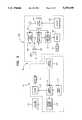
- FIG. 2is a block diagram of the pointing system according to the present invention.
- FIG. 3is a timing diagram of the signals generated in the moveable unit.
- FIG. 4is a timing diagram illustrating the technique of information reporting according to the present invention.
- FIG. 5is a block diagram of the state machine and associated logic circuitry in the moveable unit.
- FIG. 2the block diagram of the pointing system according to the present invention is shown at 40'.
- the system 40'is similar to system 40 of the prior patent (FIG. 1) in some respects and like elements are referred to by like primed reference numbers.
- the fixed unit 41'includes a driver 7' and a first LED 9'.
- a microcomputer 5'controls operation of the driver 7' as well as operation of the cursor control circuit 13' of the display device 15'.
- a power supply 11'provides power to the microcomputer 5'.
- the fixed unit 41'further includes a photodetector 43' connected to the microcomputer 5'. (The photodetector 43' may be a type which outputs a digital signal, thus eliminating the need for the A/D circuit and buffer shown in FIG. 1.)
- the moveable unit 100includes an automatic gain control (AGC) circuit 60, whereas in the prior design the fixed unit contained the active dynamic gain control circuitry.
- AGCautomatic gain control
- VFCvoltage-to-frequency converter
- a state machine 62is provided to control the operation of the AGC circuit 60 and the VFC 61, rather than a microcomputer.
- the state machineprovides simple timing to manipulate control lines to the AGC circuit 60 and the VFC 61.
- a microcomputeris not required since no actual computation is performed.
- the moveable unit 100includes a camera 19' having a lens 21' and a position sensing detector 25'. These elements are connected to both the AGC circuit 60 and to operational amplifiers 29'.
- the operational amplifiersare controlled by the AGC circuit 60 and amplify the currents generated by the detector 25' in accordance with the gain set by the AGC circuit 60, and translate these currents into proportional voltages as described with reference to FIGS. 19-21 of the prior patent.
- the operational amplifiers 29'furnish these amplified signals to the VFC 61 which generates and sends pulses to the driver 55' to activate a second LED 57'. The interval between these pulses is proportional to the voltage supplied by the operational amplifiers 29'.
- the state machinecontrols the AGC circuit 60 and the VFC 61.
- the moveable unit 100is preferably powered by a battery 53' to allow for portability.
- the active dynamic gain control circuitaltered the current applied to the LED 9 (FIG. 1), automatic gain control is performed completely in the moveable unit 100 thus eliminating closed-loop communication necessary in the prior system.
- the state machine 62which replaces the microcomputer 51 (FIG. 1) requires no memory and no calculation is performed by the state machine 62.
- the VFC 61emits pulses with separation proportional to input voltage. These pulses are sent directly to the LED 57' via the driver 55'. The result is that the data stream transmitted to the fixed unit requires less illumination duration by the LED; therefore the LED uses less battery power.
- the microcomputer 5'can measure the time interval between these pulses received by the photodetector 43' to determine the relative strengths of the voltages output by the operational amplifiers 29'. It is also possible to convert the voltages output by the operational amplifiers 29' to ratios.
- the pulses sent by the VFC 61are ratiometric in that case. In any case, a voltage proportional to the total gain applied also must be converted by the VFC 61 and reported to the fixed unit.
- the microcomputer 5'controls the driver 7' to cause the first LED 9' to illuminate in a predetermined manner. This may be by way of signals of any predetermined length, frequency and pattern. Movement of the moveable unit 100 causes the beam of light from the first LED 9' to be focused on the surface of the position sensing detector 25' in a manner corresponding to the angular rotative and/or translational relationship between the orientation of the lens 21 and the fixed position of the first LED 9'.
- Signalsare generated by the position sensing detector 25' and are conveyed to the AGC circuit 60 which controls the gain of the operational amplifiers 29'.
- the state machine 62causes the signals from the position sensing detector 25' to pass through the operational amplifiers 29' and to the VFC 61.
- the voltages generated by the operational amplifiers 29' representing each of the components of the angular rotative and/or translational relationship between the fixed unit and the moveable unit and the total gain appliedare hereinafter collectively referred to by the term "information signal”.
- the VFC 61pulses the second LED 57' in a predetermined manner to report the information related to the proportional voltages output by the position sensing detector 25' to the photodetector 43' in the fixed unit 41'.
- Such signalsare conveyed via the microcomputer 5' which receives such signals, and in response, causes the appropriate operation of the cursor control circuit 13' to move the cursor to a position on the screen.
- the state machine 62controls operations in the moveable unit 100 and has two modes: normal and powerdown.
- the powerdown modethe state machine in the moveable unit 100 has not received a signal from the fixed unit 41' in a predetermined amount of time.
- the sampling ratecan be slowed or halted to save the battery life.
- the selector button 33'To obtain the normal processing mode, the selector button 33' must be depressed otherwise the slow sampling rate will be in effect until a remote illumination pulse is received from the fixed unit. Communication between the fixed unit 41' and the remote unit 100 is based on timing the intervals between front edges of infrared pulses received by the fixed unit 41'.
- Communicationmay be initiated by either the moveable unit 100 or the fixed unit 41'.
- the moveable unitstarts by issuing two header pulses of 100 microseconds duration and 1.1 milliseconds separation.
- the fixed unit 41'uses the interval of 1.1 milliseconds to detect the request. If the fixed unit 41' detects the header, then 2 milliseconds after the first pulse of the header, the fixed unit 41' emits a 20 kHz modulated infrared pulse for 9.2 milliseconds to illuminate the photodetector of the moveable unit 100.
- PWR1 and PWR2 signalsare high for powering the operational amplifiers 29' (front end power) and the VFC 61 and other associated circuits (rear end power), respectively.
- the state machine 62activates the AGC circuit 60 to set the gain of the operational amplifiers 29' so that the voltages supplied to the VFC 61 are within a predetermined range.
- the state machine 62controls the AGC circuit 60 to set the gain of the operational amplifiers 29'. This is done by way of the AGC, AGRST, GNCLK and GNCLR pulses and includes selection of one of two gain levels.
- VFC 61All four voltages which are sampled are supplied to the VFC 61.
- a VFRST pulseis generated by the state machine 62 before each of the voltages is output sequentially to the VFC 61 (OC0, OC1, OC2 and OC3) which in response generates pulses on the V/F OUT pin separated by time intervals proportional to the magnitude of the various voltages.
- the gain set by the AGC 60called GAIN, is also converted by the VFC 61 to a time interval between successive pulses on V/F OUT.
- V/F OUTis supplied to the driver 55' which in turn drives the LED 57' to transmit the infrared pulses representative of V/F OUT.
- the signals detected by the position detector 25'(and converted to pulses) consists of give values: X+, X-, Y+, Y- and GAIN.
- This datais transmitted by the LED 57' using the pulse separation modulation scheme described above.
- the first value sentis X+.
- the timing for X+starts at 14.2 milliseconds from the first of the header pulses.
- the moveable unit 100will send a 100 microsecond pulse at 14.2 milliseconds+(25 microseconds multiplied by X+). This is called the X+ pulse.
- the fixed unit 41'determines the value for X+ by measuring the difference in time between the first of the header pulses and the rising edge of the X+ pulse subtracting 14.2 milliseconds and dividing by 25 microseconds.
- the value X-is timed based on the X+pulse plus the maximum settle time of the photodetector 43' which is 1 millisecond.
- X-is calculated as the X- pulse separation from the X+ pulse less 1 millisecond divided by 25 microseconds Y+, Y- and GAIN are similarly determined by the fixed unit.
- a TAIL pulseis sent by the moveable unit 100 1.2 milliseconds after the last piece of data (GAIN).
- the moveable unit 100sends a total of eight 100 microsecond pulses if no switch pulls are detected and the remote illumination pulse is detected.
- These pulsesare received by the photodetector 43' in the fixed unit and supplied to the microcomputer 5'.
- the fixed unit 41'the raw values X+, X-, Y+, Y- and GAIN are transformed into X and Y coordinates. This is accomplished by the microcomputer 5' using a simple ratio of the difference over the sum multiplied by a constant.
- the microcomputer 5'is activated to control the cursor control circuit 13' to move a cursor to a position aligned with the angular rotative and/or translational position of the moveable unit.
- FIG. 5is a schematic diagram of the state machine, associated decoder and logic circuitry for generating the various control signals for controlling the operational amplifiers 29', AGC circuit 60 and VFC 61.
- the state machineis driven by the START signal which is generated in response to receipt of the remote illumination pulse (FIG. 3).
- the technique of reporting data related to the orientation of the moveable unit relative to the fixed unitis also useful in pointing devices in which communication is by way of nonoptical means.
- the moveable unitneed only have some means of determining the angular rotative and/or translational position of the moveable unit.
Landscapes
- Engineering & Computer Science (AREA)
- General Engineering & Computer Science (AREA)
- Theoretical Computer Science (AREA)
- Physics & Mathematics (AREA)
- Human Computer Interaction (AREA)
- General Physics & Mathematics (AREA)
- Electromagnetism (AREA)
- Computer Networks & Wireless Communication (AREA)
- Signal Processing (AREA)
- Position Input By Displaying (AREA)
- Optical Communication System (AREA)
Abstract
Description
Claims (16)
Priority Applications (9)
| Application Number | Priority Date | Filing Date | Title |
|---|---|---|---|
| US07/886,087US5359348A (en) | 1992-05-21 | 1992-05-21 | Pointing device having improved automatic gain control and information reporting |
| AU43761/93AAU663203B2 (en) | 1992-05-21 | 1993-05-20 | Optically coupled pointing device |
| EP93913896AEP0641474A4 (en) | 1992-05-21 | 1993-05-20 | POINTING DEVICE WITH AUTOMATIC GAIN CONTROL AND TRANSMISSION OF IMPROVED INFORMATION. |
| PCT/US1993/004605WO1993023840A1 (en) | 1992-05-21 | 1993-05-20 | Pointing device having improved automatic gain control and information reporting |
| CA002136191ACA2136191A1 (en) | 1992-05-21 | 1993-05-20 | Pointing device having improved automatic gain control and information reporting |
| JP6503771AJPH08500919A (en) | 1992-05-21 | 1993-05-20 | Pointer device with improved automatic gain control and information reporting capabilities |
| FI944644AFI944644A7 (en) | 1992-05-21 | 1993-05-20 | Pointing device with improved automatic gain control and data reporting |
| NO943768ANO943768L (en) | 1992-05-21 | 1994-10-06 | Pointing device with improved automatic gain control and information reporting |
| KR94704152AKR0139479B1 (en) | 1992-05-21 | 1994-11-19 | Pointing device having improved automatic gain control and information reporting |
Applications Claiming Priority (1)
| Application Number | Priority Date | Filing Date | Title |
|---|---|---|---|
| US07/886,087US5359348A (en) | 1992-05-21 | 1992-05-21 | Pointing device having improved automatic gain control and information reporting |
Publications (1)
| Publication Number | Publication Date |
|---|---|
| US5359348Atrue US5359348A (en) | 1994-10-25 |
Family
ID=25388347
Family Applications (1)
| Application Number | Title | Priority Date | Filing Date |
|---|---|---|---|
| US07/886,087Expired - Fee RelatedUS5359348A (en) | 1992-05-21 | 1992-05-21 | Pointing device having improved automatic gain control and information reporting |
Country Status (9)
| Country | Link |
|---|---|
| US (1) | US5359348A (en) |
| EP (1) | EP0641474A4 (en) |
| JP (1) | JPH08500919A (en) |
| KR (1) | KR0139479B1 (en) |
| AU (1) | AU663203B2 (en) |
| CA (1) | CA2136191A1 (en) |
| FI (1) | FI944644A7 (en) |
| NO (1) | NO943768L (en) |
| WO (1) | WO1993023840A1 (en) |
Cited By (64)
| Publication number | Priority date | Publication date | Assignee | Title |
|---|---|---|---|---|
| US5561543A (en)* | 1994-05-02 | 1996-10-01 | Kabushikikaisha Wacom | Information input system by attitude detection of manual implement |
| FR2758639A1 (en)* | 1997-01-17 | 1998-07-24 | Samsung Electronics Co Ltd | METHOD FOR TRANSMITTING POINTING DATA FROM A REMOTE CONTROL AND METHOD FOR PROCESSING DATA RECEIVED |
| US5835156A (en)* | 1996-08-14 | 1998-11-10 | Samsung Electroncis, Ltd. | Television graphical user interface employing remote random access pointing device |
| US5920306A (en)* | 1994-03-11 | 1999-07-06 | Elonex P.L.C. | Method and apparatus for a broadcast pointer system |
| US5955988A (en)* | 1996-08-14 | 1999-09-21 | Samsung Electronics Co., Ltd. | Graphical user interface for establishing installation location for satellite based television system |
| US5978043A (en)* | 1996-08-14 | 1999-11-02 | Samsung Electronics Co., Ltd. | TV graphical user interface that provides customized lists of programming |
| US5986644A (en)* | 1997-07-30 | 1999-11-16 | Selectech, Ltd. | Remote control system |
| US5999167A (en)* | 1996-11-08 | 1999-12-07 | Stephen A. Marsh | Cursor control device |
| US6016144A (en)* | 1996-08-14 | 2000-01-18 | Samsung Electronics Co., Ltd. | Multi-layered television graphical user interface |
| US6037933A (en)* | 1996-11-13 | 2000-03-14 | Samsung Electronics Co., Ltd. | TV graphical user interface for providing user access to preset time periods of TV program information |
| US6181333B1 (en) | 1996-08-14 | 2001-01-30 | Samsung Electronics Co., Ltd. | Television graphical user interface having channel and program sorting capabilities |
| EP0759666A3 (en)* | 1995-08-10 | 2001-02-07 | Fujitsu Limited | Optical telecommunication module |
| US6191781B1 (en) | 1996-08-14 | 2001-02-20 | Samsung Electronics, Ltd. | Television graphical user interface that combines electronic program guide with graphical channel changer |
| US6195089B1 (en) | 1996-08-14 | 2001-02-27 | Samsung Electronics Co., Ltd. | Television graphical user interface having variable channel changer icons |
| US6271831B1 (en) | 1997-04-03 | 2001-08-07 | Universal Electronics Inc. | Wireless control and pointer system |
| US20020059603A1 (en)* | 2000-04-10 | 2002-05-16 | Kelts Brett R. | Interactive content guide for television programming |
| US6411308B1 (en) | 1996-08-14 | 2002-06-25 | Samsung Electronics Co., Ltd. | Television graphical user interface having variable channel control bars |
| US6636199B2 (en)* | 2000-04-07 | 2003-10-21 | Canon Kabushiki Kaisha | Coordinate input apparatus and method, coordinate input pointing device, storage medium, and computer program |
| US6738041B2 (en)* | 1999-10-29 | 2004-05-18 | Intel Corporation | Using video information to control cursor position |
| US20040252120A1 (en)* | 2003-05-08 | 2004-12-16 | Hunleth Frank A. | Systems and methods for node tracking and notification in a control framework including a zoomable graphical user interface |
| US20040252119A1 (en)* | 2003-05-08 | 2004-12-16 | Hunleth Frank A. | Systems and methods for resolution consistent semantic zooming |
| US20050125826A1 (en)* | 2003-05-08 | 2005-06-09 | Hunleth Frank A. | Control framework with a zoomable graphical user interface for organizing selecting and launching media items |
| US20050174324A1 (en)* | 2003-10-23 | 2005-08-11 | Hillcrest Communications, Inc. | User interface devices and methods employing accelerometers |
| US20050188333A1 (en)* | 2004-02-23 | 2005-08-25 | Hunleth Frank A. | Method of real-time incremental zooming |
| US20050243062A1 (en)* | 2004-04-30 | 2005-11-03 | Hillcrest Communications, Inc. | Free space pointing devices with tilt compensation and improved usability |
| US20050243061A1 (en)* | 2004-04-30 | 2005-11-03 | Hillcrest Communications, Inc. | Methods and devices for identifying users based on tremor |
| US20050270494A1 (en)* | 2004-05-28 | 2005-12-08 | Banning Erik J | Easily deployable interactive direct-pointing system and presentation control system and calibration method therefor |
| US20060028446A1 (en)* | 2004-04-30 | 2006-02-09 | Hillcrest Communications, Inc. | Methods and devices for removing unintentional movement in free space pointing devices |
| US20060150215A1 (en)* | 2005-01-05 | 2006-07-06 | Hillcrest Laboratories, Inc. | Scaling and layout methods and systems for handling one-to-many objects |
| US20060176403A1 (en)* | 2005-01-05 | 2006-08-10 | Hillcrest Laboratories, Inc. | Distributed software construction for user interfaces |
| US20060178212A1 (en)* | 2004-11-23 | 2006-08-10 | Hillcrest Laboratories, Inc. | Semantic gaming and application transformation |
| US20060184966A1 (en)* | 2005-02-14 | 2006-08-17 | Hillcrest Laboratories, Inc. | Methods and systems for enhancing television applications using 3D pointing |
| US20070013657A1 (en)* | 2005-07-13 | 2007-01-18 | Banning Erik J | Easily deployable interactive direct-pointing system and calibration method therefor |
| US20070113207A1 (en)* | 2005-11-16 | 2007-05-17 | Hillcrest Laboratories, Inc. | Methods and systems for gesture classification in 3D pointing devices |
| US7239301B2 (en) | 2004-04-30 | 2007-07-03 | Hillcrest Laboratories, Inc. | 3D pointing devices and methods |
| US20080060011A1 (en)* | 2000-12-22 | 2008-03-06 | Hillcrest Laboratories, Inc. | Zoomable user interfaces for television |
| US20080065989A1 (en)* | 2006-08-29 | 2008-03-13 | Hillcrest Laboratories, Inc. | Playlist creation tools for television user interfaces |
| US20090033807A1 (en)* | 2007-06-28 | 2009-02-05 | Hua Sheng | Real-Time Dynamic Tracking of Bias |
| US20090100373A1 (en)* | 2007-10-16 | 2009-04-16 | Hillcrest Labroatories, Inc. | Fast and smooth scrolling of user interfaces operating on thin clients |
| US7716008B2 (en) | 2007-01-19 | 2010-05-11 | Nintendo Co., Ltd. | Acceleration data processing program, and storage medium, and acceleration data processing apparatus for use with the same |
| US7774155B2 (en) | 2006-03-10 | 2010-08-10 | Nintendo Co., Ltd. | Accelerometer-based controller |
| US7786976B2 (en) | 2006-03-09 | 2010-08-31 | Nintendo Co., Ltd. | Coordinate calculating apparatus and coordinate calculating program |
| US7850527B2 (en) | 2000-02-22 | 2010-12-14 | Creative Kingdoms, Llc | Magic-themed adventure game |
| US7877224B2 (en) | 2006-03-28 | 2011-01-25 | Nintendo Co, Ltd. | Inclination calculation apparatus and inclination calculation program, and game apparatus and game program |
| US7927216B2 (en) | 2005-09-15 | 2011-04-19 | Nintendo Co., Ltd. | Video game system with wireless modular handheld controller |
| US7931535B2 (en) | 2005-08-22 | 2011-04-26 | Nintendo Co., Ltd. | Game operating device |
| US7942745B2 (en) | 2005-08-22 | 2011-05-17 | Nintendo Co., Ltd. | Game operating device |
| US8089458B2 (en) | 2000-02-22 | 2012-01-03 | Creative Kingdoms, Llc | Toy devices and methods for providing an interactive play experience |
| US8157651B2 (en) | 2005-09-12 | 2012-04-17 | Nintendo Co., Ltd. | Information processing program |
| US8226493B2 (en) | 2002-08-01 | 2012-07-24 | Creative Kingdoms, Llc | Interactive play devices for water play attractions |
| US8267786B2 (en) | 2005-08-24 | 2012-09-18 | Nintendo Co., Ltd. | Game controller and game system |
| US8308563B2 (en) | 2005-08-30 | 2012-11-13 | Nintendo Co., Ltd. | Game system and storage medium having game program stored thereon |
| US8313379B2 (en) | 2005-08-22 | 2012-11-20 | Nintendo Co., Ltd. | Video game system with wireless modular handheld controller |
| US8409003B2 (en) | 2005-08-24 | 2013-04-02 | Nintendo Co., Ltd. | Game controller and game system |
| US8475275B2 (en) | 2000-02-22 | 2013-07-02 | Creative Kingdoms, Llc | Interactive toys and games connecting physical and virtual play environments |
| US8508472B1 (en) | 2006-11-28 | 2013-08-13 | James W. Wieder | Wearable remote control with a single control button |
| US8555165B2 (en) | 2003-05-08 | 2013-10-08 | Hillcrest Laboratories, Inc. | Methods and systems for generating a zoomable graphical user interface |
| US8608535B2 (en) | 2002-04-05 | 2013-12-17 | Mq Gaming, Llc | Systems and methods for providing an interactive game |
| US8629836B2 (en) | 2004-04-30 | 2014-01-14 | Hillcrest Laboratories, Inc. | 3D pointing devices with orientation compensation and improved usability |
| US8702515B2 (en) | 2002-04-05 | 2014-04-22 | Mq Gaming, Llc | Multi-platform gaming system using RFID-tagged toys |
| US8753165B2 (en) | 2000-10-20 | 2014-06-17 | Mq Gaming, Llc | Wireless toy systems and methods for interactive entertainment |
| US8758136B2 (en) | 1999-02-26 | 2014-06-24 | Mq Gaming, Llc | Multi-platform gaming systems and methods |
| US9310887B2 (en) | 2010-05-06 | 2016-04-12 | James W. Wieder | Handheld and wearable remote-controllers |
| US9446319B2 (en) | 2003-03-25 | 2016-09-20 | Mq Gaming, Llc | Interactive gaming toy |
Families Citing this family (1)
| Publication number | Priority date | Publication date | Assignee | Title |
|---|---|---|---|---|
| CN102915138B (en)* | 2011-08-05 | 2015-09-09 | 宸鸿光电科技股份有限公司 | Sensing electrode array control circuit, control method and touch sensing system thereof |
Citations (16)
| Publication number | Priority date | Publication date | Assignee | Title |
|---|---|---|---|---|
| US4210329A (en)* | 1976-11-23 | 1980-07-01 | Loewe-Opta Gmbh | Videogame with mechanically disjoint target detector |
| US4241456A (en)* | 1978-08-30 | 1980-12-23 | Hitachi, Ltd. | Remote-controlled receiver |
| JPS60134564A (en)* | 1983-12-21 | 1985-07-17 | Matsushita Electric Ind Co Ltd | Horizontal AFC circuit |
| JPS60230228A (en)* | 1984-04-28 | 1985-11-15 | Mitsubishi Electric Corp | Picture position designating system of projection type picture reproducing device |
| US4565999A (en)* | 1983-04-01 | 1986-01-21 | Prime Computer, Inc. | Light pencil |
| EP0209411A1 (en)* | 1985-06-07 | 1987-01-21 | Thomson-Csf | Remote control system for a cursor on a screen |
| US4682159A (en)* | 1984-06-20 | 1987-07-21 | Personics Corporation | Apparatus and method for controlling a cursor on a computer display |
| US4691199A (en)* | 1985-03-05 | 1987-09-01 | Digital Equipment Corporation | Cursor position controller |
| US4839838A (en)* | 1987-03-30 | 1989-06-13 | Labiche Mitchell | Spatial input apparatus |
| US4897821A (en)* | 1986-08-18 | 1990-01-30 | Institut Francais Du Petrole | Method and device for initializing data, and particularly seismic data, acquisition apparatus |
| US4959721A (en)* | 1988-08-06 | 1990-09-25 | Deutsche Itt Industries Gmbh | Remote control system with menu driven function selection |
| US4987298A (en)* | 1989-02-09 | 1991-01-22 | Kabushiki Kaisha Toshiba | Automatic gain control apparatus which adjusts bias and gain to maximize signal to noise ratio |
| US4999617A (en)* | 1985-10-24 | 1991-03-12 | Sharp Kabushiki Kaisha | Device for reading patterns displayed on a display unit |
| US5045843A (en)* | 1988-12-06 | 1991-09-03 | Selectech, Ltd. | Optical pointing device |
| US5113151A (en)* | 1989-07-21 | 1992-05-12 | Fujitsu Limited | Equalizing and amplifying circuit in an optical signal receiving apparatus |
| US5119045A (en)* | 1990-05-07 | 1992-06-02 | Ricoh Company, Ltd. | Pulse width modulation circuit |
Family Cites Families (3)
| Publication number | Priority date | Publication date | Assignee | Title |
|---|---|---|---|---|
| JPH0720205B2 (en)* | 1985-02-28 | 1995-03-06 | キヤノン株式会社 | Sync separation circuit |
| GB2233086B (en)* | 1989-05-24 | 1993-10-13 | Apple Computer | Apparatus and method for optical encoding |
| WO1992014231A1 (en)* | 1991-02-04 | 1992-08-20 | Forte Communications, Inc. | Wireless input device with selectable channel settings |
- 1992
- 1992-05-21USUS07/886,087patent/US5359348A/ennot_activeExpired - Fee Related
- 1993
- 1993-05-20FIFI944644Apatent/FI944644A7/ennot_activeApplication Discontinuation
- 1993-05-20JPJP6503771Apatent/JPH08500919A/ennot_activeCeased
- 1993-05-20EPEP93913896Apatent/EP0641474A4/ennot_activeWithdrawn
- 1993-05-20AUAU43761/93Apatent/AU663203B2/ennot_activeCeased
- 1993-05-20CACA002136191Apatent/CA2136191A1/ennot_activeAbandoned
- 1993-05-20WOPCT/US1993/004605patent/WO1993023840A1/ennot_activeApplication Discontinuation
- 1994
- 1994-10-06NONO943768Apatent/NO943768L/enunknown
- 1994-11-19KRKR94704152Apatent/KR0139479B1/ennot_activeExpired - Fee Related
Patent Citations (17)
| Publication number | Priority date | Publication date | Assignee | Title |
|---|---|---|---|---|
| US4210329A (en)* | 1976-11-23 | 1980-07-01 | Loewe-Opta Gmbh | Videogame with mechanically disjoint target detector |
| US4241456A (en)* | 1978-08-30 | 1980-12-23 | Hitachi, Ltd. | Remote-controlled receiver |
| US4565999A (en)* | 1983-04-01 | 1986-01-21 | Prime Computer, Inc. | Light pencil |
| JPS60134564A (en)* | 1983-12-21 | 1985-07-17 | Matsushita Electric Ind Co Ltd | Horizontal AFC circuit |
| JPS60230228A (en)* | 1984-04-28 | 1985-11-15 | Mitsubishi Electric Corp | Picture position designating system of projection type picture reproducing device |
| US4682159A (en)* | 1984-06-20 | 1987-07-21 | Personics Corporation | Apparatus and method for controlling a cursor on a computer display |
| US4691199A (en)* | 1985-03-05 | 1987-09-01 | Digital Equipment Corporation | Cursor position controller |
| EP0209411A1 (en)* | 1985-06-07 | 1987-01-21 | Thomson-Csf | Remote control system for a cursor on a screen |
| US4999617A (en)* | 1985-10-24 | 1991-03-12 | Sharp Kabushiki Kaisha | Device for reading patterns displayed on a display unit |
| US4897821A (en)* | 1986-08-18 | 1990-01-30 | Institut Francais Du Petrole | Method and device for initializing data, and particularly seismic data, acquisition apparatus |
| US4839838A (en)* | 1987-03-30 | 1989-06-13 | Labiche Mitchell | Spatial input apparatus |
| US4959721A (en)* | 1988-08-06 | 1990-09-25 | Deutsche Itt Industries Gmbh | Remote control system with menu driven function selection |
| US5045843A (en)* | 1988-12-06 | 1991-09-03 | Selectech, Ltd. | Optical pointing device |
| US5045843B1 (en)* | 1988-12-06 | 1996-07-16 | Selectech Ltd | Optical pointing device |
| US4987298A (en)* | 1989-02-09 | 1991-01-22 | Kabushiki Kaisha Toshiba | Automatic gain control apparatus which adjusts bias and gain to maximize signal to noise ratio |
| US5113151A (en)* | 1989-07-21 | 1992-05-12 | Fujitsu Limited | Equalizing and amplifying circuit in an optical signal receiving apparatus |
| US5119045A (en)* | 1990-05-07 | 1992-06-02 | Ricoh Company, Ltd. | Pulse width modulation circuit |
Non-Patent Citations (2)
| Title |
|---|
| Bassen, "An Optically Linked Telemetry Sys. for Use with Electromagnetic-Field Measurement Probes", Nov. 1978, pp. 483-488. |
| Bassen, An Optically Linked Telemetry Sys. for Use with Electromagnetic Field Measurement Probes , Nov. 1978, pp. 483 488.* |
Cited By (214)
| Publication number | Priority date | Publication date | Assignee | Title |
|---|---|---|---|---|
| US5920306A (en)* | 1994-03-11 | 1999-07-06 | Elonex P.L.C. | Method and apparatus for a broadcast pointer system |
| US5561543A (en)* | 1994-05-02 | 1996-10-01 | Kabushikikaisha Wacom | Information input system by attitude detection of manual implement |
| EP0759666A3 (en)* | 1995-08-10 | 2001-02-07 | Fujitsu Limited | Optical telecommunication module |
| US5955988A (en)* | 1996-08-14 | 1999-09-21 | Samsung Electronics Co., Ltd. | Graphical user interface for establishing installation location for satellite based television system |
| US6181333B1 (en) | 1996-08-14 | 2001-01-30 | Samsung Electronics Co., Ltd. | Television graphical user interface having channel and program sorting capabilities |
| US5978043A (en)* | 1996-08-14 | 1999-11-02 | Samsung Electronics Co., Ltd. | TV graphical user interface that provides customized lists of programming |
| US6195089B1 (en) | 1996-08-14 | 2001-02-27 | Samsung Electronics Co., Ltd. | Television graphical user interface having variable channel changer icons |
| US6411308B1 (en) | 1996-08-14 | 2002-06-25 | Samsung Electronics Co., Ltd. | Television graphical user interface having variable channel control bars |
| US6016144A (en)* | 1996-08-14 | 2000-01-18 | Samsung Electronics Co., Ltd. | Multi-layered television graphical user interface |
| US6191781B1 (en) | 1996-08-14 | 2001-02-20 | Samsung Electronics, Ltd. | Television graphical user interface that combines electronic program guide with graphical channel changer |
| US5835156A (en)* | 1996-08-14 | 1998-11-10 | Samsung Electroncis, Ltd. | Television graphical user interface employing remote random access pointing device |
| US5999167A (en)* | 1996-11-08 | 1999-12-07 | Stephen A. Marsh | Cursor control device |
| US6037933A (en)* | 1996-11-13 | 2000-03-14 | Samsung Electronics Co., Ltd. | TV graphical user interface for providing user access to preset time periods of TV program information |
| US6034662A (en)* | 1997-01-17 | 2000-03-07 | Samsung Electronics Co., Ltd. | Method for transmitting remote controller pointing data and method for processing received data |
| FR2758639A1 (en)* | 1997-01-17 | 1998-07-24 | Samsung Electronics Co Ltd | METHOD FOR TRANSMITTING POINTING DATA FROM A REMOTE CONTROL AND METHOD FOR PROCESSING DATA RECEIVED |
| US6271831B1 (en) | 1997-04-03 | 2001-08-07 | Universal Electronics Inc. | Wireless control and pointer system |
| US5986644A (en)* | 1997-07-30 | 1999-11-16 | Selectech, Ltd. | Remote control system |
| US8758136B2 (en) | 1999-02-26 | 2014-06-24 | Mq Gaming, Llc | Multi-platform gaming systems and methods |
| US10300374B2 (en) | 1999-02-26 | 2019-05-28 | Mq Gaming, Llc | Multi-platform gaming systems and methods |
| US9186585B2 (en) | 1999-02-26 | 2015-11-17 | Mq Gaming, Llc | Multi-platform gaming systems and methods |
| US9731194B2 (en) | 1999-02-26 | 2017-08-15 | Mq Gaming, Llc | Multi-platform gaming systems and methods |
| US8888576B2 (en) | 1999-02-26 | 2014-11-18 | Mq Gaming, Llc | Multi-media interactive play system |
| US9468854B2 (en) | 1999-02-26 | 2016-10-18 | Mq Gaming, Llc | Multi-platform gaming systems and methods |
| US9861887B1 (en) | 1999-02-26 | 2018-01-09 | Mq Gaming, Llc | Multi-platform gaming systems and methods |
| US6738041B2 (en)* | 1999-10-29 | 2004-05-18 | Intel Corporation | Using video information to control cursor position |
| US9814973B2 (en) | 2000-02-22 | 2017-11-14 | Mq Gaming, Llc | Interactive entertainment system |
| US8368648B2 (en) | 2000-02-22 | 2013-02-05 | Creative Kingdoms, Llc | Portable interactive toy with radio frequency tracking device |
| US10188953B2 (en) | 2000-02-22 | 2019-01-29 | Mq Gaming, Llc | Dual-range wireless interactive entertainment device |
| US8686579B2 (en) | 2000-02-22 | 2014-04-01 | Creative Kingdoms, Llc | Dual-range wireless controller |
| US7850527B2 (en) | 2000-02-22 | 2010-12-14 | Creative Kingdoms, Llc | Magic-themed adventure game |
| US8708821B2 (en) | 2000-02-22 | 2014-04-29 | Creative Kingdoms, Llc | Systems and methods for providing interactive game play |
| US10307671B2 (en) | 2000-02-22 | 2019-06-04 | Mq Gaming, Llc | Interactive entertainment system |
| US8164567B1 (en) | 2000-02-22 | 2012-04-24 | Creative Kingdoms, Llc | Motion-sensitive game controller with optional display screen |
| US8475275B2 (en) | 2000-02-22 | 2013-07-02 | Creative Kingdoms, Llc | Interactive toys and games connecting physical and virtual play environments |
| US8790180B2 (en) | 2000-02-22 | 2014-07-29 | Creative Kingdoms, Llc | Interactive game and associated wireless toy |
| US8814688B2 (en) | 2000-02-22 | 2014-08-26 | Creative Kingdoms, Llc | Customizable toy for playing a wireless interactive game having both physical and virtual elements |
| US8491389B2 (en) | 2000-02-22 | 2013-07-23 | Creative Kingdoms, Llc. | Motion-sensitive input device and interactive gaming system |
| US8184097B1 (en) | 2000-02-22 | 2012-05-22 | Creative Kingdoms, Llc | Interactive gaming system and method using motion-sensitive input device |
| US9713766B2 (en) | 2000-02-22 | 2017-07-25 | Mq Gaming, Llc | Dual-range wireless interactive entertainment device |
| US8915785B2 (en) | 2000-02-22 | 2014-12-23 | Creative Kingdoms, Llc | Interactive entertainment system |
| US9579568B2 (en) | 2000-02-22 | 2017-02-28 | Mq Gaming, Llc | Dual-range wireless interactive entertainment device |
| US8089458B2 (en) | 2000-02-22 | 2012-01-03 | Creative Kingdoms, Llc | Toy devices and methods for providing an interactive play experience |
| US9149717B2 (en) | 2000-02-22 | 2015-10-06 | Mq Gaming, Llc | Dual-range wireless interactive entertainment device |
| US9474962B2 (en) | 2000-02-22 | 2016-10-25 | Mq Gaming, Llc | Interactive entertainment system |
| US8169406B2 (en) | 2000-02-22 | 2012-05-01 | Creative Kingdoms, Llc | Motion-sensitive wand controller for a game |
| US6636199B2 (en)* | 2000-04-07 | 2003-10-21 | Canon Kabushiki Kaisha | Coordinate input apparatus and method, coordinate input pointing device, storage medium, and computer program |
| US9552128B2 (en) | 2000-04-10 | 2017-01-24 | Hillcrest Laboratories, Inc. | Media user interfaces using metadata from different sources |
| US7139983B2 (en) | 2000-04-10 | 2006-11-21 | Hillcrest Laboratories, Inc. | Interactive content guide for television programming |
| US20020059603A1 (en)* | 2000-04-10 | 2002-05-16 | Kelts Brett R. | Interactive content guide for television programming |
| US8046804B2 (en) | 2000-04-10 | 2011-10-25 | Hillcrest Laboratories, Inc. | Media user interfaces using metadata from different sources |
| US20080060010A1 (en)* | 2000-04-10 | 2008-03-06 | Hillcrest Laboratories, Inc. | Media user interfaces using metadata from different sources |
| US7844987B2 (en) | 2000-04-10 | 2010-11-30 | Hillcrest Laboratories, Inc. | Interactive content guide for television programming |
| US20060218588A1 (en)* | 2000-04-10 | 2006-09-28 | Hillcrest Laboratories, Inc. | Interactive content guide for television programming |
| US20060218587A1 (en)* | 2000-04-10 | 2006-09-28 | Hillcrest Laboratories, Inc. | Interactive content guide for television programming |
| US10307683B2 (en) | 2000-10-20 | 2019-06-04 | Mq Gaming, Llc | Toy incorporating RFID tag |
| US9320976B2 (en) | 2000-10-20 | 2016-04-26 | Mq Gaming, Llc | Wireless toy systems and methods for interactive entertainment |
| US9480929B2 (en) | 2000-10-20 | 2016-11-01 | Mq Gaming, Llc | Toy incorporating RFID tag |
| US8961260B2 (en) | 2000-10-20 | 2015-02-24 | Mq Gaming, Llc | Toy incorporating RFID tracking device |
| US9931578B2 (en) | 2000-10-20 | 2018-04-03 | Mq Gaming, Llc | Toy incorporating RFID tag |
| US8753165B2 (en) | 2000-10-20 | 2014-06-17 | Mq Gaming, Llc | Wireless toy systems and methods for interactive entertainment |
| US20080060020A1 (en)* | 2000-12-22 | 2008-03-06 | Hillcrest Laboratories, Inc. | Methods and systems for semantic zooming |
| US20080082927A1 (en)* | 2000-12-22 | 2008-04-03 | Hillcrest Laboratories, Inc. | Methods and systems for personalizing a user interface |
| US20080060011A1 (en)* | 2000-12-22 | 2008-03-06 | Hillcrest Laboratories, Inc. | Zoomable user interfaces for television |
| US20080060009A1 (en)* | 2000-12-22 | 2008-03-06 | Hillcrest Laboratories, Inc. | Client/server methods and systems for generating a user interface |
| US8384668B2 (en) | 2001-02-22 | 2013-02-26 | Creative Kingdoms, Llc | Portable gaming device and gaming system combining both physical and virtual play elements |
| US9393491B2 (en) | 2001-02-22 | 2016-07-19 | Mq Gaming, Llc | Wireless entertainment device, system, and method |
| US9162148B2 (en) | 2001-02-22 | 2015-10-20 | Mq Gaming, Llc | Wireless entertainment device, system, and method |
| US8711094B2 (en) | 2001-02-22 | 2014-04-29 | Creative Kingdoms, Llc | Portable gaming device and gaming system combining both physical and virtual play elements |
| US10758818B2 (en) | 2001-02-22 | 2020-09-01 | Mq Gaming, Llc | Wireless entertainment device, system, and method |
| US9737797B2 (en) | 2001-02-22 | 2017-08-22 | Mq Gaming, Llc | Wireless entertainment device, system, and method |
| US8248367B1 (en) | 2001-02-22 | 2012-08-21 | Creative Kingdoms, Llc | Wireless gaming system combining both physical and virtual play elements |
| US8913011B2 (en) | 2001-02-22 | 2014-12-16 | Creative Kingdoms, Llc | Wireless entertainment device, system, and method |
| US10179283B2 (en) | 2001-02-22 | 2019-01-15 | Mq Gaming, Llc | Wireless entertainment device, system, and method |
| US8608535B2 (en) | 2002-04-05 | 2013-12-17 | Mq Gaming, Llc | Systems and methods for providing an interactive game |
| US9463380B2 (en) | 2002-04-05 | 2016-10-11 | Mq Gaming, Llc | System and method for playing an interactive game |
| US10478719B2 (en) | 2002-04-05 | 2019-11-19 | Mq Gaming, Llc | Methods and systems for providing personalized interactive entertainment |
| US8702515B2 (en) | 2002-04-05 | 2014-04-22 | Mq Gaming, Llc | Multi-platform gaming system using RFID-tagged toys |
| US10507387B2 (en) | 2002-04-05 | 2019-12-17 | Mq Gaming, Llc | System and method for playing an interactive game |
| US10010790B2 (en) | 2002-04-05 | 2018-07-03 | Mq Gaming, Llc | System and method for playing an interactive game |
| US9616334B2 (en) | 2002-04-05 | 2017-04-11 | Mq Gaming, Llc | Multi-platform gaming system using RFID-tagged toys |
| US8827810B2 (en) | 2002-04-05 | 2014-09-09 | Mq Gaming, Llc | Methods for providing interactive entertainment |
| US11278796B2 (en) | 2002-04-05 | 2022-03-22 | Mq Gaming, Llc | Methods and systems for providing personalized interactive entertainment |
| US9272206B2 (en) | 2002-04-05 | 2016-03-01 | Mq Gaming, Llc | System and method for playing an interactive game |
| US8226493B2 (en) | 2002-08-01 | 2012-07-24 | Creative Kingdoms, Llc | Interactive play devices for water play attractions |
| US9446319B2 (en) | 2003-03-25 | 2016-09-20 | Mq Gaming, Llc | Interactive gaming toy |
| US9993724B2 (en) | 2003-03-25 | 2018-06-12 | Mq Gaming, Llc | Interactive gaming toy |
| US8961312B2 (en) | 2003-03-25 | 2015-02-24 | Creative Kingdoms, Llc | Motion-sensitive controller and associated gaming applications |
| US11052309B2 (en) | 2003-03-25 | 2021-07-06 | Mq Gaming, Llc | Wireless interactive game having both physical and virtual elements |
| US9039533B2 (en) | 2003-03-25 | 2015-05-26 | Creative Kingdoms, Llc | Wireless interactive game having both physical and virtual elements |
| US10583357B2 (en) | 2003-03-25 | 2020-03-10 | Mq Gaming, Llc | Interactive gaming toy |
| US9393500B2 (en) | 2003-03-25 | 2016-07-19 | Mq Gaming, Llc | Wireless interactive game having both physical and virtual elements |
| US8373659B2 (en) | 2003-03-25 | 2013-02-12 | Creative Kingdoms, Llc | Wirelessly-powered toy for gaming |
| US9707478B2 (en) | 2003-03-25 | 2017-07-18 | Mq Gaming, Llc | Motion-sensitive controller and associated gaming applications |
| US10369463B2 (en) | 2003-03-25 | 2019-08-06 | Mq Gaming, Llc | Wireless interactive game having both physical and virtual elements |
| US9770652B2 (en) | 2003-03-25 | 2017-09-26 | Mq Gaming, Llc | Wireless interactive game having both physical and virtual elements |
| US10022624B2 (en) | 2003-03-25 | 2018-07-17 | Mq Gaming, Llc | Wireless interactive game having both physical and virtual elements |
| US8046705B2 (en) | 2003-05-08 | 2011-10-25 | Hillcrest Laboratories, Inc. | Systems and methods for resolution consistent semantic zooming |
| US20050125826A1 (en)* | 2003-05-08 | 2005-06-09 | Hunleth Frank A. | Control framework with a zoomable graphical user interface for organizing selecting and launching media items |
| US8555165B2 (en) | 2003-05-08 | 2013-10-08 | Hillcrest Laboratories, Inc. | Methods and systems for generating a zoomable graphical user interface |
| US20040252119A1 (en)* | 2003-05-08 | 2004-12-16 | Hunleth Frank A. | Systems and methods for resolution consistent semantic zooming |
| US20040252120A1 (en)* | 2003-05-08 | 2004-12-16 | Hunleth Frank A. | Systems and methods for node tracking and notification in a control framework including a zoomable graphical user interface |
| US7834849B2 (en) | 2003-05-08 | 2010-11-16 | Hillcrest Laboratories, Inc. | Control framework with a zoomable graphical user interface for organizing selecting and launching media items |
| US8601396B2 (en) | 2003-05-08 | 2013-12-03 | Hillcrest Laboratories, Inc. | Systems and methods for node tracking and notification in a control framework including a zoomable graphical user interface |
| US20050174324A1 (en)* | 2003-10-23 | 2005-08-11 | Hillcrest Communications, Inc. | User interface devices and methods employing accelerometers |
| US7489299B2 (en) | 2003-10-23 | 2009-02-10 | Hillcrest Laboratories, Inc. | User interface devices and methods employing accelerometers |
| US20050188333A1 (en)* | 2004-02-23 | 2005-08-25 | Hunleth Frank A. | Method of real-time incremental zooming |
| US7260789B2 (en) | 2004-02-23 | 2007-08-21 | Hillcrest Laboratories, Inc. | Method of real-time incremental zooming |
| US9304651B2 (en) | 2004-02-23 | 2016-04-05 | Hillcrest Laboratories, Inc. | Method of real-time incremental zooming |
| US9946356B2 (en) | 2004-04-30 | 2018-04-17 | Interdigital Patent Holdings, Inc. | 3D pointing devices with orientation compensation and improved usability |
| US20050243061A1 (en)* | 2004-04-30 | 2005-11-03 | Hillcrest Communications, Inc. | Methods and devices for identifying users based on tremor |
| US20080158155A1 (en)* | 2004-04-30 | 2008-07-03 | Hillcrest Laboratories, Inc. | Methods and devices for indentifying users based on tremor |
| US7414611B2 (en) | 2004-04-30 | 2008-08-19 | Hillcrest Laboratories, Inc. | 3D pointing devices with orientation compensation and improved usability |
| US8629836B2 (en) | 2004-04-30 | 2014-01-14 | Hillcrest Laboratories, Inc. | 3D pointing devices with orientation compensation and improved usability |
| US20070247425A1 (en)* | 2004-04-30 | 2007-10-25 | Hillcrest Laboratories, Inc. | Methods and devices for identifying users based on tremor |
| US7262760B2 (en) | 2004-04-30 | 2007-08-28 | Hillcrest Laboratories, Inc. | 3D pointing devices with orientation compensation and improved usability |
| US9298282B2 (en) | 2004-04-30 | 2016-03-29 | Hillcrest Laboratories, Inc. | 3D pointing devices with orientation compensation and improved usability |
| US11157091B2 (en) | 2004-04-30 | 2021-10-26 | Idhl Holdings, Inc. | 3D pointing devices and methods |
| US9575570B2 (en) | 2004-04-30 | 2017-02-21 | Hillcrest Laboratories, Inc. | 3D pointing devices and methods |
| US8072424B2 (en) | 2004-04-30 | 2011-12-06 | Hillcrest Laboratories, Inc. | 3D pointing devices with orientation compensation and improved usability |
| US7239301B2 (en) | 2004-04-30 | 2007-07-03 | Hillcrest Laboratories, Inc. | 3D pointing devices and methods |
| US10782792B2 (en) | 2004-04-30 | 2020-09-22 | Idhl Holdings, Inc. | 3D pointing devices with orientation compensation and improved usability |
| US8766917B2 (en) | 2004-04-30 | 2014-07-01 | Hillcrest Laboratories, Inc. | 3D pointing devices and methods |
| US7236156B2 (en) | 2004-04-30 | 2007-06-26 | Hillcrest Laboratories, Inc. | Methods and devices for identifying users based on tremor |
| US9261978B2 (en) | 2004-04-30 | 2016-02-16 | Hillcrest Laboratories, Inc. | 3D pointing devices and methods |
| US7158118B2 (en) | 2004-04-30 | 2007-01-02 | Hillcrest Laboratories, Inc. | 3D pointing devices with orientation compensation and improved usability |
| US10514776B2 (en) | 2004-04-30 | 2019-12-24 | Idhl Holdings, Inc. | 3D pointing devices and methods |
| US8237657B2 (en) | 2004-04-30 | 2012-08-07 | Hillcrest Laboratories, Inc. | Methods and devices for removing unintentional movement in 3D pointing devices |
| US20080291163A1 (en)* | 2004-04-30 | 2008-11-27 | Hillcrest Laboratories, Inc. | 3D Pointing Devices with Orientation Compensation and Improved Usability |
| US20050243062A1 (en)* | 2004-04-30 | 2005-11-03 | Hillcrest Communications, Inc. | Free space pointing devices with tilt compensation and improved usability |
| US20090128489A1 (en)* | 2004-04-30 | 2009-05-21 | Liberty Matthew G | Methods and devices for removing unintentional movement in 3d pointing devices |
| US7535456B2 (en) | 2004-04-30 | 2009-05-19 | Hillcrest Laboratories, Inc. | Methods and devices for removing unintentional movement in 3D pointing devices |
| US20080158154A1 (en)* | 2004-04-30 | 2008-07-03 | Hillcrest Laboratories, Inc. | 3D pointing devices and methods |
| US8937594B2 (en) | 2004-04-30 | 2015-01-20 | Hillcrest Laboratories, Inc. | 3D pointing devices with orientation compensation and improved usability |
| US7489298B2 (en) | 2004-04-30 | 2009-02-10 | Hillcrest Laboratories, Inc. | 3D pointing devices and methods |
| US20060028446A1 (en)* | 2004-04-30 | 2006-02-09 | Hillcrest Communications, Inc. | Methods and devices for removing unintentional movement in free space pointing devices |
| US8994657B2 (en) | 2004-04-30 | 2015-03-31 | Hillcrest Laboratories, Inc. | Methods and devices for identifying users based on tremor |
| US11073919B2 (en) | 2004-05-28 | 2021-07-27 | UltimatePointer, L.L.C. | Multi-sensor device with an accelerometer for enabling user interaction through sound or image |
| US8049729B2 (en) | 2004-05-28 | 2011-11-01 | Erik Jan Banning | Easily deployable interactive direct-pointing system and presentation control system and calibration method therefor |
| US9411437B2 (en) | 2004-05-28 | 2016-08-09 | UltimatePointer, L.L.C. | Easily deployable interactive direct-pointing system and presentation control system and calibration method therefor |
| US11755127B2 (en) | 2004-05-28 | 2023-09-12 | UltimatePointer, L.L.C. | Multi-sensor device with an accelerometer for enabling user interaction through sound or image |
| US20050270494A1 (en)* | 2004-05-28 | 2005-12-08 | Banning Erik J | Easily deployable interactive direct-pointing system and presentation control system and calibration method therefor |
| US9785255B2 (en) | 2004-05-28 | 2017-10-10 | UltimatePointer, L.L.C. | Apparatus for controlling contents of a computer-generated image using three dimensional measurements |
| US8866742B2 (en) | 2004-05-28 | 2014-10-21 | Ultimatepointer, Llc | Easily deployable interactive direct-pointing system and presentation control system and calibration method therefor |
| US7746321B2 (en) | 2004-05-28 | 2010-06-29 | Erik Jan Banning | Easily deployable interactive direct-pointing system and presentation control system and calibration method therefor |
| US11416084B2 (en) | 2004-05-28 | 2022-08-16 | UltimatePointer, L.L.C. | Multi-sensor device with an accelerometer for enabling user interaction through sound or image |
| US11409376B2 (en) | 2004-05-28 | 2022-08-09 | UltimatePointer, L.L.C. | Multi-sensor device with an accelerometer for enabling user interaction through sound or image |
| US9063586B2 (en) | 2004-05-28 | 2015-06-23 | Ultimatepointer, Llc | Easily deployable interactive direct-pointing system and presentation control system and calibration method therefor |
| US20100283732A1 (en)* | 2004-05-28 | 2010-11-11 | Erik Jan Banning | Easily deployable interactive direct-pointing system and presentation control system and calibration method therefor |
| US11402927B2 (en) | 2004-05-28 | 2022-08-02 | UltimatePointer, L.L.C. | Pointing device |
| US9675878B2 (en) | 2004-09-29 | 2017-06-13 | Mq Gaming, Llc | System and method for playing a virtual game by sensing physical movements |
| US11154776B2 (en) | 2004-11-23 | 2021-10-26 | Idhl Holdings, Inc. | Semantic gaming and application transformation |
| US10159897B2 (en) | 2004-11-23 | 2018-12-25 | Idhl Holdings, Inc. | Semantic gaming and application transformation |
| US8137195B2 (en) | 2004-11-23 | 2012-03-20 | Hillcrest Laboratories, Inc. | Semantic gaming and application transformation |
| US8795079B2 (en) | 2004-11-23 | 2014-08-05 | Hillcrest Laboratories, Inc. | Semantic gaming and application transformation including movement processing equations based on inertia |
| US20060178212A1 (en)* | 2004-11-23 | 2006-08-10 | Hillcrest Laboratories, Inc. | Semantic gaming and application transformation |
| US7386806B2 (en) | 2005-01-05 | 2008-06-10 | Hillcrest Laboratories, Inc. | Scaling and layout methods and systems for handling one-to-many objects |
| US20060150215A1 (en)* | 2005-01-05 | 2006-07-06 | Hillcrest Laboratories, Inc. | Scaling and layout methods and systems for handling one-to-many objects |
| US20080235735A1 (en)* | 2005-01-05 | 2008-09-25 | Wroblewski Frank J | Scaling and Layout Methods and Systems for Handling One-To-Many Objects |
| US20060176403A1 (en)* | 2005-01-05 | 2006-08-10 | Hillcrest Laboratories, Inc. | Distributed software construction for user interfaces |
| US7839385B2 (en) | 2005-02-14 | 2010-11-23 | Hillcrest Laboratories, Inc. | Methods and systems for enhancing television applications using 3D pointing |
| US8432358B2 (en) | 2005-02-14 | 2013-04-30 | Hillcrest Laboratories, Inc. | Methods and systems for enhancing television applications using 3D pointing |
| US20110067068A1 (en)* | 2005-02-14 | 2011-03-17 | Hillcrest Laboratories, Inc. | Methods and Systems for Enhancing Television Applications Using 3D Pointing |
| US8169405B2 (en) | 2005-02-14 | 2012-05-01 | Hillcrest Laboratories, Inc. | Methods and systems for enhancing television applications using 3D pointing |
| US9436359B2 (en) | 2005-02-14 | 2016-09-06 | Hillcrest Laboratories, Inc. | Methods and systems for enhancing television applications using 3D pointing |
| US20060184966A1 (en)* | 2005-02-14 | 2006-08-17 | Hillcrest Laboratories, Inc. | Methods and systems for enhancing television applications using 3D pointing |
| US10372237B2 (en) | 2005-07-13 | 2019-08-06 | UltimatePointer, L.L.C. | Apparatus for controlling contents of a computer-generated image using 3D measurements |
| US20070013657A1 (en)* | 2005-07-13 | 2007-01-18 | Banning Erik J | Easily deployable interactive direct-pointing system and calibration method therefor |
| US9285897B2 (en) | 2005-07-13 | 2016-03-15 | Ultimate Pointer, L.L.C. | Easily deployable interactive direct-pointing system and calibration method therefor |
| US11841997B2 (en) | 2005-07-13 | 2023-12-12 | UltimatePointer, L.L.C. | Apparatus for controlling contents of a computer-generated image using 3D measurements |
| US9498728B2 (en) | 2005-08-22 | 2016-11-22 | Nintendo Co., Ltd. | Game operating device |
| US10238978B2 (en) | 2005-08-22 | 2019-03-26 | Nintendo Co., Ltd. | Game operating device |
| US9700806B2 (en) | 2005-08-22 | 2017-07-11 | Nintendo Co., Ltd. | Game operating device |
| US7942745B2 (en) | 2005-08-22 | 2011-05-17 | Nintendo Co., Ltd. | Game operating device |
| US9011248B2 (en) | 2005-08-22 | 2015-04-21 | Nintendo Co., Ltd. | Game operating device |
| US7931535B2 (en) | 2005-08-22 | 2011-04-26 | Nintendo Co., Ltd. | Game operating device |
| US10155170B2 (en) | 2005-08-22 | 2018-12-18 | Nintendo Co., Ltd. | Game operating device with holding portion detachably holding an electronic device |
| US8313379B2 (en) | 2005-08-22 | 2012-11-20 | Nintendo Co., Ltd. | Video game system with wireless modular handheld controller |
| US10661183B2 (en) | 2005-08-22 | 2020-05-26 | Nintendo Co., Ltd. | Game operating device |
| US8409003B2 (en) | 2005-08-24 | 2013-04-02 | Nintendo Co., Ltd. | Game controller and game system |
| US9044671B2 (en) | 2005-08-24 | 2015-06-02 | Nintendo Co., Ltd. | Game controller and game system |
| US9498709B2 (en) | 2005-08-24 | 2016-11-22 | Nintendo Co., Ltd. | Game controller and game system |
| US8267786B2 (en) | 2005-08-24 | 2012-09-18 | Nintendo Co., Ltd. | Game controller and game system |
| US8834271B2 (en) | 2005-08-24 | 2014-09-16 | Nintendo Co., Ltd. | Game controller and game system |
| US10137365B2 (en) | 2005-08-24 | 2018-11-27 | Nintendo Co., Ltd. | Game controller and game system |
| US9227138B2 (en) | 2005-08-24 | 2016-01-05 | Nintendo Co., Ltd. | Game controller and game system |
| US11027190B2 (en) | 2005-08-24 | 2021-06-08 | Nintendo Co., Ltd. | Game controller and game system |
| US8870655B2 (en) | 2005-08-24 | 2014-10-28 | Nintendo Co., Ltd. | Wireless game controllers |
| US8308563B2 (en) | 2005-08-30 | 2012-11-13 | Nintendo Co., Ltd. | Game system and storage medium having game program stored thereon |
| US8708824B2 (en) | 2005-09-12 | 2014-04-29 | Nintendo Co., Ltd. | Information processing program |
| US8157651B2 (en) | 2005-09-12 | 2012-04-17 | Nintendo Co., Ltd. | Information processing program |
| USRE45905E1 (en) | 2005-09-15 | 2016-03-01 | Nintendo Co., Ltd. | Video game system with wireless modular handheld controller |
| US8430753B2 (en) | 2005-09-15 | 2013-04-30 | Nintendo Co., Ltd. | Video game system with wireless modular handheld controller |
| US7927216B2 (en) | 2005-09-15 | 2011-04-19 | Nintendo Co., Ltd. | Video game system with wireless modular handheld controller |
| US20070113207A1 (en)* | 2005-11-16 | 2007-05-17 | Hillcrest Laboratories, Inc. | Methods and systems for gesture classification in 3D pointing devices |
| US7786976B2 (en) | 2006-03-09 | 2010-08-31 | Nintendo Co., Ltd. | Coordinate calculating apparatus and coordinate calculating program |
| US7774155B2 (en) | 2006-03-10 | 2010-08-10 | Nintendo Co., Ltd. | Accelerometer-based controller |
| US8473245B2 (en) | 2006-03-28 | 2013-06-25 | Nintendo Co., Ltd. | Inclination calculation apparatus and inclination calculation program, and game apparatus and game program |
| US7877224B2 (en) | 2006-03-28 | 2011-01-25 | Nintendo Co, Ltd. | Inclination calculation apparatus and inclination calculation program, and game apparatus and game program |
| US8041536B2 (en) | 2006-03-28 | 2011-10-18 | Nintendo Co., Ltd. | Inclination calculation apparatus and inclination calculation program, and game apparatus and game program |
| US20080065989A1 (en)* | 2006-08-29 | 2008-03-13 | Hillcrest Laboratories, Inc. | Playlist creation tools for television user interfaces |
| US20110219395A1 (en)* | 2006-08-29 | 2011-09-08 | Hillcrest Laboratories, Inc. | Pointing Capability and Associated User Interface Elements for Television User Interfaces |
| US9369659B2 (en) | 2006-08-29 | 2016-06-14 | Hillcrest Laboratories, Inc. | Pointing capability and associated user interface elements for television user interfaces |
| US8508472B1 (en) | 2006-11-28 | 2013-08-13 | James W. Wieder | Wearable remote control with a single control button |
| US7716008B2 (en) | 2007-01-19 | 2010-05-11 | Nintendo Co., Ltd. | Acceleration data processing program, and storage medium, and acceleration data processing apparatus for use with the same |
| US8683850B2 (en) | 2007-06-28 | 2014-04-01 | Hillcrest Laboratories, Inc. | Real-time dynamic tracking of bias |
| US8407022B2 (en) | 2007-06-28 | 2013-03-26 | Hillcrest Laboratories, Inc. | Real-time dynamic tracking of bias |
| US9250716B2 (en) | 2007-06-28 | 2016-02-02 | Hillcrest Laboratories, Inc. | Real-time dynamic tracking of bias |
| US20110095979A1 (en)* | 2007-06-28 | 2011-04-28 | Hillcrest Laboratories, Inc. | Real-Time Dynamic Tracking of Bias |
| US7860676B2 (en) | 2007-06-28 | 2010-12-28 | Hillcrest Laboratories, Inc. | Real-time dynamic tracking of bias |
| US20090033807A1 (en)* | 2007-06-28 | 2009-02-05 | Hua Sheng | Real-Time Dynamic Tracking of Bias |
| US9400598B2 (en) | 2007-10-16 | 2016-07-26 | Hillcrest Laboratories, Inc. | Fast and smooth scrolling of user interfaces operating on thin clients |
| US20090100373A1 (en)* | 2007-10-16 | 2009-04-16 | Hillcrest Labroatories, Inc. | Fast and smooth scrolling of user interfaces operating on thin clients |
| US8359545B2 (en) | 2007-10-16 | 2013-01-22 | Hillcrest Laboratories, Inc. | Fast and smooth scrolling of user interfaces operating on thin clients |
| US9310887B2 (en) | 2010-05-06 | 2016-04-12 | James W. Wieder | Handheld and wearable remote-controllers |
Also Published As
| Publication number | Publication date |
|---|---|
| FI944644L (en) | 1994-11-21 |
| KR0139479B1 (en) | 1998-07-15 |
| FI944644A7 (en) | 1994-11-21 |
| NO943768D0 (en) | 1994-10-06 |
| EP0641474A4 (en) | 1998-06-03 |
| AU4376193A (en) | 1993-12-13 |
| JPH08500919A (en) | 1996-01-30 |
| WO1993023840A1 (en) | 1993-11-25 |
| CA2136191A1 (en) | 1993-11-25 |
| EP0641474A1 (en) | 1995-03-08 |
| FI944644A0 (en) | 1994-10-05 |
| NO943768L (en) | 1995-01-19 |
| AU663203B2 (en) | 1995-09-28 |
Similar Documents
| Publication | Publication Date | Title |
|---|---|---|
| US5359348A (en) | Pointing device having improved automatic gain control and information reporting | |
| EP0736837A2 (en) | Point-type radio controller using infrared rays | |
| US7221437B1 (en) | Method and apparatus for measuring distances using light | |
| CA2151537A1 (en) | Electric field sensor capable of reliably measuring an electric field intensity of a signal | |
| US5602568A (en) | Point type remote control apparatus and the method thereof | |
| US4810891A (en) | Method for the automatic identification of the type of measuring head of a fiber optic measurement value acquisition and transmission device | |
| US7247834B2 (en) | Photoelectric sensor for detecting presence/absence of object | |
| KR950013165B1 (en) | Point-type wireless controller using infrared rags | |
| KR0144177B1 (en) | Point type wireless controller using ultrasonic wave | |
| JPH07167954A (en) | Distance measuring device | |
| JP2747187B2 (en) | Photoelectric switch | |
| JP3266999B2 (en) | Vehicle detection device | |
| JPH0562882U (en) | Distance measuring device | |
| JP2732911B2 (en) | Article detection method | |
| JP3137854B2 (en) | Relative angle detector | |
| US20050185168A1 (en) | Multifunction rangefinder | |
| JP3137852B2 (en) | Relative angle detector | |
| JP3076617B2 (en) | Method and apparatus for adjusting sensitivity of photoelectric switch | |
| CN223066627U (en) | Laser control system | |
| JP2600462B2 (en) | Optical receiving circuit | |
| JPH08163037A (en) | Relative angle detector | |
| JP2568587B2 (en) | Air puff tonometer | |
| KR0147126B1 (en) | A point type remote controller using frequency division method | |
| JPH0712557A (en) | Laser distance-measuring sensor | |
| JPH043139B2 (en) |
Legal Events
| Date | Code | Title | Description |
|---|---|---|---|
| AS | Assignment | Owner name:SELECTECH, INC., VERMONT Free format text:ASSIGNMENT OF ASSIGNORS INTEREST;ASSIGNORS:PILCHER, STEPHEN L.;ODELL, DONALD S.;REEL/FRAME:006604/0158 Effective date:19930624 | |
| AS | Assignment | Owner name:SELECTECH, LTD., VERMONT Free format text:RE-RECORD TO CORRECT ASSIGNEE NAME PREVIOUSLY RECORDED ON 6604 FRAME 0158.;ASSIGNORS:PILCHER, STEPHEN L.;ODELL, DONALD S.;REEL/FRAME:006763/0095 Effective date:19930624 | |
| FPAY | Fee payment | Year of fee payment:4 | |
| AS | Assignment | Owner name:ENOTE.COM, INC., VERMONT Free format text:ASSIGNMENT OF ASSIGNORS INTEREST;ASSIGNOR:SELECTECH, LTD.;REEL/FRAME:010247/0107 Effective date:19990823 | |
| AS | Assignment | Owner name:RICHARDS, III.,JAMES D. AND MARTINE RICHARDS, VERM Free format text:ASSIGNMENT OF ASSIGNORS INTEREST;ASSIGNOR:ENOTE.COM, INC.;REEL/FRAME:012607/0360 Effective date:20010402 | |
| REMI | Maintenance fee reminder mailed | ||
| LAPS | Lapse for failure to pay maintenance fees | ||
| STCH | Information on status: patent discontinuation | Free format text:PATENT EXPIRED DUE TO NONPAYMENT OF MAINTENANCE FEES UNDER 37 CFR 1.362 | |
| FP | Lapsed due to failure to pay maintenance fee | Effective date:20021025 |