US5358035A - Control cartridge for controlling a safety valve in an operating well - Google Patents
Control cartridge for controlling a safety valve in an operating wellDownload PDFInfo
- Publication number
- US5358035A US5358035AUS08/117,536US11753693AUS5358035AUS 5358035 AUS5358035 AUS 5358035AUS 11753693 AUS11753693 AUS 11753693AUS 5358035 AUS5358035 AUS 5358035A
- Authority
- US
- United States
- Prior art keywords
- hydraulic fluid
- pressure
- actuator
- receiver
- low
- Prior art date
- Legal status (The legal status is an assumption and is not a legal conclusion. Google has not performed a legal analysis and makes no representation as to the accuracy of the status listed.)
- Expired - Lifetime
Links
Images

Classifications
- E—FIXED CONSTRUCTIONS
- E21—EARTH OR ROCK DRILLING; MINING
- E21B—EARTH OR ROCK DRILLING; OBTAINING OIL, GAS, WATER, SOLUBLE OR MELTABLE MATERIALS OR A SLURRY OF MINERALS FROM WELLS
- E21B34/00—Valve arrangements for boreholes or wells
- E21B34/06—Valve arrangements for boreholes or wells in wells
- E21B34/066—Valve arrangements for boreholes or wells in wells electrically actuated
Definitions
- the present inventionrelates to a cartridge that is designed to be mounted in the tubing of an operating well, for example an oil well, in order to control the opening and closing of a safety valve located at a certain depth in the tubing and through which a fluid such as oil being drilled can flow.
- a first object of the present inventionis to provide for the automatic and rapid closing of a safety valve. It is a further object of the invention to provide for the automatic and rapid closing of a safety valve such as a gate valve, also referred to as a flapper valve, or, for that matter, any other type of valve used in oil wells, such as spherical plug valves.
- a safety valvesuch as a gate valve, also referred to as a flapper valve, or, for that matter, any other type of valve used in oil wells, such as spherical plug valves.
- Such automatic or voluntary closing of the safety valvemay be good for safety reasons as well as for preventing pollution of the environment, for example by preventing oil from being spilled into the marine environment from an off-shore oil drilling platform.
- control cartridgewhich controls the closing of a safety valve mounted in the tubing of an operating well.
- the control cartridge according to the present inventionhas a cartridge housing mounted in the tubing.
- a receiverfurther, is provided for receiving transmitted control signals from a remote location, such as from ground level or an ocean platform.
- a power supplyis further provided in the housing, and an electronic control system in the housing is connected to both the receiver and the power supply.
- the safety valveis controlled by a hydraulically operated actuator.
- a source of hydraulic fluid in the housingconnected with the hydraulically operated actuator for operating the actuator.
- the source of hydraulic fluidis further connected to the power supply.
- the actuatorincludes a high-pressure hydraulic fluid tank that has a piston rod extending therefrom to the exterior of the housing.
- the piston rodthen operably engages the safety valve.
- the source of hydraulic fluidincludes a low-pressure hydraulic fluid tank that is defined in the housing.
- a hydraulic pumpis immersed in this low pressure tank for receiving low-pressure hydraulic fluid therefrom, and has a discharge pipe that connects the pump to the high-pressure hydraulic fluid tank of the actuator.
- a motoris connected to the power supply and to the hydraulic pump for driving the hydraulic pump.
- the high-pressure hydraulic fluid tankis also immersed in the low-pressure hydraulic fluid tank.
- the high-pressure hydraulic fluid tankpreferably has a fluid connection connecting it to the low-pressure fluid tank as well as an electronically controlled valve in the fluid connection that is controlled by the electronic control system.
- the fluid connectionfurther, preferably includes a connection pipe having a free end that defines a valve seat.
- the electronically controlled valveincludes a sealing member for sealing against the valve seat, a spring for biasing the sealing member against the valve seat and an electromagnet having a coil forming a solenoid and a ferromagnetic core rod engaging the spring for biasing the sealing member against the valve seat when the electromagnet is provided with a current.
- the electronic control systemincludes a control card capable of reading coded signals from the receiver and supplying current from the power supply to the electromagnet in response to the coded signals.
- a position sensoris provided for sensing the position of the actuator.
- the position sensoris connected with the electronic control system so that the position sensor and the electronic control system together define a means for stopping advance of the actuator when the actuator has advanced to a predetermined position.
- the electronic control system and the position sensorfurther define a means for automatically compensating for leaks of hydraulic fluid from the high-pressure hydraulic fluid tank by causing the source of hydraulic fluid to supply more hydraulic fluid upon the actuator retracting beyond a threshold amount from its extended position.
- the receiverincludes an antenna that is positioned inside the tubing.
- the receiveris an electromagnetic signal receiver capable of receiving electromagnetic signals transmitted through the ground.
- the receivercould also be a pressure sensor mounted on the tubing capable of receiving acoustic signals propagated through fluid in the tubing.
- the receivercould include a pressure sensor that is mounted on an upper portion of the housing of the control cartridge, similarly capable of receiving acoustic signals propagated through fluid in the tubing.
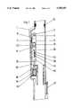
- FIG. 1is a schematic and partial cross-sectional view of a control cartridge according to the present invention as provided in tubing of an operating well;
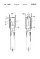
- FIG. 2is a schematic, cross-sectional view of the control cartridge of FIG. 1 corresponding to an open position of a safety valve;
- FIG. 3is a view similar to FIG. 2 but corresponding to a closed position of the safety valve
- FIG. 4is a schematic, cross-sectional view of the control cartridge according to the present invention illustrating the position of a pressure sensor on the tubing of the well;
- FIG. 5is a view similar to FIG. 4 illustrating the position of a pressure sensor on the control cartridge.
- an elongated control cartridge 1 in accordance with the present inventionmounted in the tubing of an operating well such as an oil well.
- the elongated control cartridgeis designed to be inserted into the tubing and attached beneath a packer in the tubing (not shown).
- the elongated cartridgeincludes an assembly mandrel 2 connected with a housing 3 of the control cartridge.
- the control cartridge 1further includes an electromagnetic receiver generally designated by reference numeral 4.
- the receiver 4includes, in the embodiment of FIG. 1, an antenna 5 that is positioned inside the tubing for receiving electromagnetic signals transmitted from the surface, a magnetic coupler 6 and cables or wires 7 connecting the magnetic coupler 6 to the antenna 5.
- the magnetic coupler 6makes it possible to connect, without contact, the antenna 5 to the control cartridge 1. Note FIG. 2, wherein the arrangement of the magnetic coupler is more particularly illustrated.
- the control cartridge 1further includes a power supply 8, which preferably comprises a set of batteries, for supplying power to an electronic control system 9, also mounted in the control cartridge 1, and a geared motor 10.
- a power supply 8which preferably comprises a set of batteries, for supplying power to an electronic control system 9, also mounted in the control cartridge 1, and a geared motor 10.
- the geared motor 10, mounted in the control cartridge 1,has an output shaft 11 driving a hydraulic pump 12.
- a low-pressure oil tank 13is defined inside the housing 3 of the control cartridge 1. Note also FIGS. 2 and 3.
- the hydraulic pump 12is immersed in the low-pressure oil tank 13 so that the low-pressure oil tank 13 is employed as the source of hydraulic fluid (oil) for the hydraulic pump 12.
- the hydraulic pump 12has a discharge pipe 14 that extends to and is connected with an actuator.
- the actuatorincludes a high-pressure tank 15 fluidly connected with the discharge pipe, thus receiving pressurized hydraulic fluid (oil) from the hydraulic pump 12.
- the piston rod 16has its position controlled by a position sensor 17, schematically illustrated in FIG. 1. As further illustrated in FIG. 1, the piston rod 16 can extend from the control cartridge 1 to engage a frontal element 18 of a cover 19 that encloses a spring 20 associated with a flapper valve 21.
- the flapper valve 21is designed so as to seal the tubing in order to halt the flow of the fluid being drilled. Thus, when the piston rod 16 is extended from the control cartridge 1, the flapper valve 21 will be open, and when the piston rod 16 is retracted into the housing as shown in FIG. 3, the flapper valve 21 will be closed.
- FIGS. 2 and 3more particularly illustrate the elements involved in the operation of the control cartridge 1 according to the present invention in controlling the flapper valve 21.
- FIG. 2shows the situation wherein the piston rod 16 is extended to open the flapper valve 21
- FIG. 3shows the situation wherein the piston rod 16 is retracted to close the flapper valve 21.
- an electromagnetic wave train Tcauses a signal to be sent through the magnetic coupler 6 to the electronic control system 9.
- a control card 23as part of the electronic control system 9, is illustrated as connected to the magnetic coupler 6 through further cables or wires 7.
- the control card 23is capable of reading a coded signal in the electromagnetic wave train T being transmitted thereto.
- connection wires 24 and 25extend from the control card 23 of the electronic control system 9 to an electromagnet 26.
- the electromagnet 26has a solenoid 27 and a magnetic core 28.
- a connection pipe 32connects the high-pressure hydraulic fluid tank 15 to the low-pressure hydraulic fluid tank 13.
- the end of the connection pipe 32forms a valve seat 31 providing a seat for a valve member 30.
- a spring 29is acted on by the magnetic core 28 and engages the valve member 30 such that the spring tends to bias the valve member into engagement with the valve seat 31.
- the magnetic core 28can be activated by a current running through the solenoid 27 to act on the spring 29 and bias the valve member 30 into engagement with the valve seat 31 to close the connection pipe 32 in the open position of the flapper valve 21, i.e. with the piston rod 16 extended.
- FIG. 3corresponds substantially to FIG. 2, except that FIG. 3 illustrates the closed position of the flapper valve 21.
- the control card 23receives no control signal, as schematically illustrated in FIG. 3, no current is supplied to the solenoid 27.
- the magnetic core 28is in the position as illustrated in FIG. 3 and allows the valve member 30 to permit the high-pressure hydraulic fluid in the tank 15 to escape through the connection pipe 32 into the low-pressure tank 13.
- the magnetic core 28would be automatically retracted and the high-pressure hydraulic fluid inside the tank 15 would be allowed to escape through the connection pipe 32, thus allowing the flapper valve 21 to move into the closed position.
- a breakdown of the control cartridge 1results in the automatic closing of the safety flapper valve 21.
- FIG. 4shows an alternate embodiment wherein the receiver includes a pressure sensor 33.
- the pressure sensor 33is connected to the magnetic coupler 6, and is mounted on the inside of the tubing of the well.
- the pressure sensor 33is designed so as to be capable of receiving acoustic signals transmitted through the fluid in the annular section of the well.
- acoustic signals C transmitted through the fluid in the annular section of the wellwill be received by the pressure sensor 33 on the tubing and transmitted by means of the magnetic coupler 6 to the control card 23 of the electronic control system 9.
- the acoustic signalsmay have frequencies between 1 and 30 Hz. Otherwise, the operation of the control cartridge 1 of FIG. 4, controlled by acoustic signals, is the same as the operation described with respect to FIGS. 2 and 3.
- FIG. 5illustrates the mounting of a sensor 34 in the upper part of the control cartridge 1.
- the sensor 34is similar to the pressure sensor 33 in that the sensor 34 is capable of receiving acoustic signals C.
- the acoustic signalsare transmitted from the surface through the fluid contained in the well tubing. It is noted that in the case of FIG. 5, the use of a magnetic coupler 6 can be eliminated.
- the electronic control systemcan establish a threshold amount of retraction allowable by the piston rod 16 while the piston rod 16 is in the open position of the valve 21 such that once the piston rod 16 goes beyond this threshold value, the hydraulic pump 12 is re-actuated so as to reestablish the initial position of the piston rod 16.
Landscapes
- Life Sciences & Earth Sciences (AREA)
- Engineering & Computer Science (AREA)
- Geology (AREA)
- Mining & Mineral Resources (AREA)
- Physics & Mathematics (AREA)
- Environmental & Geological Engineering (AREA)
- Fluid Mechanics (AREA)
- General Life Sciences & Earth Sciences (AREA)
- Geochemistry & Mineralogy (AREA)
- Fluid-Pressure Circuits (AREA)
- Magnetically Actuated Valves (AREA)
Abstract
Description
The present invention relates to a cartridge that is designed to be mounted in the tubing of an operating well, for example an oil well, in order to control the opening and closing of a safety valve located at a certain depth in the tubing and through which a fluid such as oil being drilled can flow.
A first object of the present invention is to provide for the automatic and rapid closing of a safety valve. It is a further object of the invention to provide for the automatic and rapid closing of a safety valve such as a gate valve, also referred to as a flapper valve, or, for that matter, any other type of valve used in oil wells, such as spherical plug valves.
It is a second object of the present invention to enable the voluntary closing of a valve located at a relatively significant depth in well tubing from either ground level or from an ocean platform, either with or without an access code as desired.
It is a further object of the present invention to provide for either voluntary rapid closing, or automatic closing, of a safety valve in a drilling well, in particular during oil drilling operations. Such automatic or voluntary closing of the safety valve may be good for safety reasons as well as for preventing pollution of the environment, for example by preventing oil from being spilled into the marine environment from an off-shore oil drilling platform.
The above-discussed objects of the present invention are achieved in accordance with the present invention by the provision of a control cartridge which controls the closing of a safety valve mounted in the tubing of an operating well.
The control cartridge according to the present invention has a cartridge housing mounted in the tubing. A receiver, further, is provided for receiving transmitted control signals from a remote location, such as from ground level or an ocean platform. A power supply is further provided in the housing, and an electronic control system in the housing is connected to both the receiver and the power supply. The safety valve is controlled by a hydraulically operated actuator. There is thus further provided a source of hydraulic fluid in the housing connected with the hydraulically operated actuator for operating the actuator. The source of hydraulic fluid is further connected to the power supply.
Preferably, the actuator includes a high-pressure hydraulic fluid tank that has a piston rod extending therefrom to the exterior of the housing. The piston rod then operably engages the safety valve.
Further, the source of hydraulic fluid includes a low-pressure hydraulic fluid tank that is defined in the housing. A hydraulic pump is immersed in this low pressure tank for receiving low-pressure hydraulic fluid therefrom, and has a discharge pipe that connects the pump to the high-pressure hydraulic fluid tank of the actuator. A motor is connected to the power supply and to the hydraulic pump for driving the hydraulic pump. The high-pressure hydraulic fluid tank is also immersed in the low-pressure hydraulic fluid tank.
Further, the high-pressure hydraulic fluid tank preferably has a fluid connection connecting it to the low-pressure fluid tank as well as an electronically controlled valve in the fluid connection that is controlled by the electronic control system. The fluid connection, further, preferably includes a connection pipe having a free end that defines a valve seat. The electronically controlled valve includes a sealing member for sealing against the valve seat, a spring for biasing the sealing member against the valve seat and an electromagnet having a coil forming a solenoid and a ferromagnetic core rod engaging the spring for biasing the sealing member against the valve seat when the electromagnet is provided with a current.
According to a further preferred feature of the present invention, the electronic control system includes a control card capable of reading coded signals from the receiver and supplying current from the power supply to the electromagnet in response to the coded signals.
A position sensor, further, is provided for sensing the position of the actuator. The position sensor is connected with the electronic control system so that the position sensor and the electronic control system together define a means for stopping advance of the actuator when the actuator has advanced to a predetermined position. Further, the electronic control system and the position sensor further define a means for automatically compensating for leaks of hydraulic fluid from the high-pressure hydraulic fluid tank by causing the source of hydraulic fluid to supply more hydraulic fluid upon the actuator retracting beyond a threshold amount from its extended position.
In one form of the receiver, the receiver includes an antenna that is positioned inside the tubing. In this form of the receiver, the receiver is an electromagnetic signal receiver capable of receiving electromagnetic signals transmitted through the ground.
However, the receiver could also be a pressure sensor mounted on the tubing capable of receiving acoustic signals propagated through fluid in the tubing. Alternatively, the receiver could include a pressure sensor that is mounted on an upper portion of the housing of the control cartridge, similarly capable of receiving acoustic signals propagated through fluid in the tubing.
Further features and advantages of the present invention will become apparent from the following detailed description of preferred embodiments of the invention with reference to the accompanying drawings figures, wherein:
FIG. 1 is a schematic and partial cross-sectional view of a control cartridge according to the present invention as provided in tubing of an operating well;
FIG. 2 is a schematic, cross-sectional view of the control cartridge of FIG. 1 corresponding to an open position of a safety valve;
FIG. 3 is a view similar to FIG. 2 but corresponding to a closed position of the safety valve;
FIG. 4 is a schematic, cross-sectional view of the control cartridge according to the present invention illustrating the position of a pressure sensor on the tubing of the well; and
FIG. 5 is a view similar to FIG. 4 illustrating the position of a pressure sensor on the control cartridge.
Referring initially to FIG. 1, there can be seen an elongated control cartridge 1 in accordance with the present invention mounted in the tubing of an operating well such as an oil well. The elongated control cartridge is designed to be inserted into the tubing and attached beneath a packer in the tubing (not shown).
Initially, the elongated cartridge includes anassembly mandrel 2 connected with a housing 3 of the control cartridge.
The control cartridge 1 further includes an electromagnetic receiver generally designated byreference numeral 4. Thereceiver 4 includes, in the embodiment of FIG. 1, an antenna 5 that is positioned inside the tubing for receiving electromagnetic signals transmitted from the surface, amagnetic coupler 6 and cables orwires 7 connecting themagnetic coupler 6 to the antenna 5. Themagnetic coupler 6 makes it possible to connect, without contact, the antenna 5 to the control cartridge 1. Note FIG. 2, wherein the arrangement of the magnetic coupler is more particularly illustrated.
The control cartridge 1 further includes apower supply 8, which preferably comprises a set of batteries, for supplying power to anelectronic control system 9, also mounted in the control cartridge 1, and a gearedmotor 10.
As can be seen from FIG. 1, the gearedmotor 10, mounted in the control cartridge 1, has anoutput shaft 11 driving ahydraulic pump 12.
A low-pressure oil tank 13 is defined inside the housing 3 of the control cartridge 1. Note also FIGS. 2 and 3. Thehydraulic pump 12 is immersed in the low-pressure oil tank 13 so that the low-pressure oil tank 13 is employed as the source of hydraulic fluid (oil) for thehydraulic pump 12.
Thehydraulic pump 12 has adischarge pipe 14 that extends to and is connected with an actuator. The actuator includes a high-pressure tank 15 fluidly connected with the discharge pipe, thus receiving pressurized hydraulic fluid (oil) from thehydraulic pump 12. A piston rod orjack rod 16 extending from the high-pressure tank 15, as illustrated in FIGS. 2 and 3, is thus operated by the supply of pressurized hydraulic fluid to the high-pressure tank 15.
Thepiston rod 16 has its position controlled by aposition sensor 17, schematically illustrated in FIG. 1. As further illustrated in FIG. 1, thepiston rod 16 can extend from the control cartridge 1 to engage afrontal element 18 of acover 19 that encloses aspring 20 associated with aflapper valve 21. Theflapper valve 21 is designed so as to seal the tubing in order to halt the flow of the fluid being drilled. Thus, when thepiston rod 16 is extended from the control cartridge 1, theflapper valve 21 will be open, and when thepiston rod 16 is retracted into the housing as shown in FIG. 3, theflapper valve 21 will be closed.
Theposition sensor 17, connected to theelectronic control system 9, senses the position of thepiston rod 16 so as to stop thehydraulic pump 12 when thepiston rod 16 reaches the end of its extension stroke. Further, if there is a leak of hydraulic fluid from the high-pressure tank 15, for example, theposition sensor 17 can also control thehydraulic pump 12 to restart and supply more hydraulic fluid when thepiston rod 16 tends to retract. A threshold value of the amount of retraction can be set. As can be further schematically seen in the drawings, in particular noting FIG. 1, a pressure-compensation diaphragm in the form of asleeve 22 is provided at the level of the gearedmotor 10.
FIGS. 2 and 3 more particularly illustrate the elements involved in the operation of the control cartridge 1 according to the present invention in controlling theflapper valve 21. FIG. 2 shows the situation wherein thepiston rod 16 is extended to open theflapper valve 21, and FIG. 3 shows the situation wherein thepiston rod 16 is retracted to close theflapper valve 21.
As illustrated in FIG. 2, an electromagnetic wave train T causes a signal to be sent through themagnetic coupler 6 to theelectronic control system 9. In FIGS. 2 and 3, acontrol card 23, as part of theelectronic control system 9, is illustrated as connected to themagnetic coupler 6 through further cables orwires 7. Thecontrol card 23 is capable of reading a coded signal in the electromagnetic wave train T being transmitted thereto.
Twoconnection wires control card 23 of theelectronic control system 9 to anelectromagnet 26. Theelectromagnet 26 has asolenoid 27 and amagnetic core 28. Further, aconnection pipe 32 connects the high-pressurehydraulic fluid tank 15 to the low-pressurehydraulic fluid tank 13. The end of theconnection pipe 32 forms avalve seat 31 providing a seat for avalve member 30. Aspring 29 is acted on by themagnetic core 28 and engages thevalve member 30 such that the spring tends to bias the valve member into engagement with thevalve seat 31.
As still illustrated in FIG. 2, themagnetic core 28 can be activated by a current running through thesolenoid 27 to act on thespring 29 and bias thevalve member 30 into engagement with thevalve seat 31 to close theconnection pipe 32 in the open position of theflapper valve 21, i.e. with thepiston rod 16 extended.
FIG. 3 corresponds substantially to FIG. 2, except that FIG. 3 illustrates the closed position of theflapper valve 21. When thecontrol card 23 receives no control signal, as schematically illustrated in FIG. 3, no current is supplied to thesolenoid 27. Thus, themagnetic core 28 is in the position as illustrated in FIG. 3 and allows thevalve member 30 to permit the high-pressure hydraulic fluid in thetank 15 to escape through theconnection pipe 32 into the low-pressure tank 13. Thus it can be seen that if there is a breakdown in the operation of the control cartridge 1, themagnetic core 28 would be automatically retracted and the high-pressure hydraulic fluid inside thetank 15 would be allowed to escape through theconnection pipe 32, thus allowing theflapper valve 21 to move into the closed position. Thus a breakdown of the control cartridge 1 results in the automatic closing of thesafety flapper valve 21.
FIG. 4 shows an alternate embodiment wherein the receiver includes apressure sensor 33. Thepressure sensor 33 is connected to themagnetic coupler 6, and is mounted on the inside of the tubing of the well. Thepressure sensor 33 is designed so as to be capable of receiving acoustic signals transmitted through the fluid in the annular section of the well. Thus, acoustic signals C transmitted through the fluid in the annular section of the well will be received by thepressure sensor 33 on the tubing and transmitted by means of themagnetic coupler 6 to thecontrol card 23 of theelectronic control system 9. The acoustic signals may have frequencies between 1 and 30 Hz. Otherwise, the operation of the control cartridge 1 of FIG. 4, controlled by acoustic signals, is the same as the operation described with respect to FIGS. 2 and 3.
FIG. 5 illustrates the mounting of asensor 34 in the upper part of the control cartridge 1. Thesensor 34 is similar to thepressure sensor 33 in that thesensor 34 is capable of receiving acoustic signals C. In this case, the acoustic signals are transmitted from the surface through the fluid contained in the well tubing. It is noted that in the case of FIG. 5, the use of amagnetic coupler 6 can be eliminated.
According to further features of the present invention, provided in order to refine the operation of the control cartridge 1, provision may be made so as to ensure that theposition sensor 17 will stop the advance of thepiston rod 16 once thevalve 21 is completely open. Further, theposition sensor 17 can also automatically compensate for leaks from the high-pressure tank 15. The electronic control system can establish a threshold amount of retraction allowable by thepiston rod 16 while thepiston rod 16 is in the open position of thevalve 21 such that once thepiston rod 16 goes beyond this threshold value, thehydraulic pump 12 is re-actuated so as to reestablish the initial position of thepiston rod 16.
Preferred embodiments of the present invention have been described and illustrated for purposes of explanation and not so as to limit the scope of protection of the present invention. Various modifications in the details of the present invention could be made to the preferred embodiments thereof, accordingly, while still remaining within the scope of the present invention. For example, the electronic control system illustrated and described could be used to control any device capable of motion when acted upon by hydraulic pressure. In particular, this system could be used for different types of valves.
Claims (30)
1. An operating well, having: well tubing;
a safety valve in said well tubing; and
a control cartridge for controlling the safety valve, said control cartridge comprising:
a cartridge housing mounted in said well tubing;
a receiver for receiving transmitted control signals;
a power supply provided in said housing;
an electronic control system in said housing connected to both said receiver and said power supply;
a hydraulically operated actuator for controlling the safety valve; and
a source of hydraulic fluid in said housing connected with said hydraulically operated actuator for operating said actuator, said source of hydraulic fluid being connected to said power supply.
2. The operation well of claim 1, wherein said actuator comprises a high-pressure hydraulic fluid tank having a piston rod extending therefrom to the exterior of said housing, said piston rod operably engaging said safety valve.
3. The operating well of claim 2, wherein said source of hydraulic fluid comprises a low-pressure hydraulic fluid tank defined in said housing, a hydraulic pump immersed in said low-pressure tank for receiving low-pressure hydraulic fluid therefrom and having a discharge pipe connecting said pump to said high-pressure hydraulic fluid tank, and a motor connected to said power supply and to said hydraulic pump for driving said hydraulic pump, wherein said high-pressure hydraulic fluid tank is also immersed in said low-pressure hydraulic fluid tank.
4. The operating well of claim 3, wherein said high-pressure hydraulic fluid tank has a fluid connection to said low-pressure fluid tank and an electronically controlled valve in said fluid connection controlled by said electronic control system.
5. The operating well of claim 4, wherein said fluid connection comprises a connection pipe having a free end that defines a valve seat, and said electronically controlled valve comprises a sealing member for sealing against said valve seat, a spring for biasing said sealing member against said valve seat and an electromagnet having a coil forming a solenoid and a ferromagnetic core rod engaging said spring for biasing said sealing member against said valve seat when said electromagnet is provided with a current.
6. The operating well of claim 5, wherein said electronic control system includes a control card capable of reading coded signals from said receiver and supplying current from said power supply to said electromagnet in response to said coded signals.
7. The operating well of claim 2, wherein said high-pressure hydraulic fluid tank has a fluid connection to a low-pressure fluid tank and an electronically controlled valve in said fluid connection controlled by said electronic control system.
8. The operating well of claim 7, wherein said fluid connection comprises a connection pipe having a free end that defines a valve seat, and said electronically controlled valve comprises a sealing member for sealing against said valve seat, a spring for biasing said sealing member against said valve seat and an electromagnet having a coil forming a solenoid and a ferromagnetic core rod engaging said spring for biasing said sealing member against said valve seat when said electromagnet is provided with a current.
9. The operating well of claim 8, wherein said electronic control system includes a control card capable of reading coded signals from said receiver and supplying current from said power supply to said electromagnet in response to said coded signals.
10. The operating well of claim 1, wherein said source of hydraulic fluid comprises a low-pressure hydraulic fluid tank defined in said housing, a hydraulic pump immersed in said low-pressure tank for receiving low-pressure hydraulic fluid therefrom and having a discharge pipe connecting said pump to said actuator, and a motor connected to said power supply and to said hydraulic pump for driving said hydraulic pump, and wherein said actuator is also immersed in said low-pressure hydraulic fluid tank.
11. The operating well of claim 1, wherein a position sensor is provided for sensing the position of said actuator, said position sensor being connected with said electronic control system, said position sensor and said electronic control system together defining a means for stopping advance of said actuator when said actuator has advanced to a predetermined position, and for automatically compensating for leaks of hydraulic fluid by causing said source of hydraulic fluid to supply hydraulic fluid to said actuator upon said actuator retracting beyond a threshold amount.
12. The operating well of claim 1, wherein said receiver comprises an antenna positioned inside said tubing and a magnetic coupler connected to both said antenna and to said electronic control system.
13. The operating well of claim 1, wherein said receiver is an electromagnetic signal receiver capable of receiving electromagnetic signals transmitted through the ground.
14. The operating well of claim 1, wherein said receiver includes a pressure sensor mounted on said tubing capable of receiving acoustic signals propagated through fluid in said tubing.
15. The operating well of claim 1, wherein said receiver includes a pressure sensor mounted on an upper portion of said housing capable of receiving acoustic signals propagated through fluid in said tubing.
16. A control cartridge for use in controlling a safety valve in an operating well, comprising:
a cartridge housing;
a receiver for receiving transmitted control signals;
a power supply provided in said housing;
an electronic control system in said housing connected to both said receiver and said power supply;
a hydraulically operated actuator for controlling the safety valve; and
a source of hydraulic fluid in said housing connected with said hydraulically operated actuator for operating said actuator, said source of hydraulic fluid being connected to said power supply.
17. The control cartridge of claim 16, wherein said actuator comprises a high-pressure hydraulic fluid tank having a piston rod extending therefrom to the exterior of said housing for operably engaging the safety valve.
18. The control cartridge of claim 17, wherein said source of hydraulic fluid comprises a low-pressure hydraulic fluid tank defined in said housing, a hydraulic pump immersed in said low-pressure tank for receiving low-pressure hydraulic fluid therefrom and having a discharge pipe connecting said pump to said high-pressure hydraulic fluid tank, and a motor connected to said power supply and to said hydraulic pump for driving said hydraulic pump, wherein said high-pressure hydraulic fluid tank is also immersed in said low-pressure hydraulic fluid tank.
19. The control cartridge of claim 18, wherein said high-pressure hydraulic fluid tank has a fluid connection to said low-pressure fluid tank and an electronically controlled valve in said fluid connection controlled by said electronic control system.
20. The control cartridge of claim 19, wherein said fluid connection comprises a connection pipe having a free end that defines a valve seat, and said electronically controlled valve comprises a sealing member for sealing against said valve seat, a spring for biasing said sealing member against said valve seat and an electromagnet having a coil forming a solenoid and a ferromagnetic core rod engaging said spring for biasing said sealing member against said valve seat when said electromagnet is provided with a current.
21. The control cartridge of claim 20, wherein said electronic control system includes a control card capable of reading coded signals from said receiver and supplying current from said power supply to said electromagnet in response to said coded signals.
22. The control cartridge of claim 17, wherein said high-pressure hydraulic fluid tank has a fluid connection to a low-pressure fluid tank and an electronically controlled valve in said fluid connection controlled by said electronic control system.
23. The control cartridge of claim 22, wherein said fluid connection comprises a connection pipe having a free end that defines a valve seat, and said electronically controlled valve comprises a sealing member for sealing against said valve seat, a spring for biasing said sealing member against said valve seat and an electromagnet having a coil forming a solenoid and a ferromagnetic core rod engaging said spring for biasing said sealing member against said valve seat when said electromagnet is provided with a current.
24. The control cartridge of claim 23, wherein said electronic control system includes a control card capable of reading coded signals from said receiver and supplying current from said power supply to said electromagnet in response to said coded signals.
25. The control cartridge of claim 16, wherein said source of hydraulic fluid comprises a low-pressure hydraulic fluid tank defined in said housing, a hydraulic pump immersed in said low-pressure tank for receiving low-pressure hydraulic fluid therefrom and having a discharge pipe connecting said pump to said actuator, and a motor connected to said power supply and to said hydraulic pump for driving said hydraulic pump, and wherein said actuator is also immersed in said low-pressure hydraulic fluid tank.
26. The control cartridge of claim 16, wherein a position sensor is provided for sensing the position of said actuator, said position sensor being connected with said electronic control system, said position sensor and said electronic control system together defining a means for stopping advance of said actuator when said actuator has advanced to a predetermined position, and for automatically compensating for leaks of hydraulic fluid by causing said source of hydraulic fluid to supply hydraulic fluid to said actuator upon said actuator retracting beyond a threshold amount.
27. The control cartridge of claim 16, wherein said receiver comprises an antenna and a magnetic coupler connected to both said antenna and to said electronic control system.
28. The control cartridge of claim 16, wherein said receiver is an electromagnetic signal receiver capable of receiving electromagnetic signals transmitted through the ground.
29. The control cartridge of claim 16, wherein said receiver includes a pressure sensor capable of receiving acoustic signals propagated through fluid.
30. The control cartridge of claim 16, wherein said receiver includes a pressure sensor mounted on an upper portion of said housing capable of receiving acoustic signals propagated through fluid.
Applications Claiming Priority (2)
| Application Number | Priority Date | Filing Date | Title |
|---|---|---|---|
| FR9210647AFR2695450B1 (en) | 1992-09-07 | 1992-09-07 | Safety valve control and command cartridge. |
| FR9210647 | 1992-09-07 |
Publications (1)
| Publication Number | Publication Date |
|---|---|
| US5358035Atrue US5358035A (en) | 1994-10-25 |
Family
ID=9433261
Family Applications (1)
| Application Number | Title | Priority Date | Filing Date |
|---|---|---|---|
| US08/117,536Expired - LifetimeUS5358035A (en) | 1992-09-07 | 1993-09-07 | Control cartridge for controlling a safety valve in an operating well |
Country Status (4)
| Country | Link |
|---|---|
| US (1) | US5358035A (en) |
| CA (1) | CA2105526C (en) |
| FR (1) | FR2695450B1 (en) |
| GB (1) | GB2270707B (en) |
Cited By (70)
| Publication number | Priority date | Publication date | Assignee | Title |
|---|---|---|---|---|
| US5465786A (en)* | 1994-05-27 | 1995-11-14 | Dresser Industries, Inc. | Subsurface tubing safety valve |
| US5597042A (en)* | 1995-02-09 | 1997-01-28 | Baker Hughes Incorporated | Method for controlling production wells having permanent downhole formation evaluation sensors |
| US5662165A (en)* | 1995-02-09 | 1997-09-02 | Baker Hughes Incorporated | Production wells having permanent downhole formation evaluation sensors |
| US5706892A (en)* | 1995-02-09 | 1998-01-13 | Baker Hughes Incorporated | Downhole tools for production well control |
| US5706896A (en)* | 1995-02-09 | 1998-01-13 | Baker Hughes Incorporated | Method and apparatus for the remote control and monitoring of production wells |
| US5730219A (en)* | 1995-02-09 | 1998-03-24 | Baker Hughes Incorporated | Production wells having permanent downhole formation evaluation sensors |
| US5732776A (en)* | 1995-02-09 | 1998-03-31 | Baker Hughes Incorporated | Downhole production well control system and method |
| US5896924A (en)* | 1997-03-06 | 1999-04-27 | Baker Hughes Incorporated | Computer controlled gas lift system |
| US5960883A (en)* | 1995-02-09 | 1999-10-05 | Baker Hughes Incorporated | Power management system for downhole control system in a well and method of using same |
| GB2337065A (en)* | 1998-05-05 | 1999-11-10 | Baker Hughes Inc | Electro-hydraulic actuator for a subsurface safety valve or tool |
| US6006832A (en)* | 1995-02-09 | 1999-12-28 | Baker Hughes Incorporated | Method and system for monitoring and controlling production and injection wells having permanent downhole formation evaluation sensors |
| US6012015A (en)* | 1995-02-09 | 2000-01-04 | Baker Hughes Incorporated | Control model for production wells |
| US6065538A (en)* | 1995-02-09 | 2000-05-23 | Baker Hughes Corporation | Method of obtaining improved geophysical information about earth formations |
| US6075462A (en)* | 1997-11-24 | 2000-06-13 | Smith; Harrison C. | Adjacent well electromagnetic telemetry system and method for use of the same |
| US6138754A (en)* | 1998-11-18 | 2000-10-31 | Schlumberger Technology Corporation | Method and apparatus for use with submersible electrical equipment |
| US6160492A (en)* | 1998-07-17 | 2000-12-12 | Halliburton Energy Services, Inc. | Through formation electromagnetic telemetry system and method for use of the same |
| US6199629B1 (en) | 1997-09-24 | 2001-03-13 | Baker Hughes Incorporated | Computer controlled downhole safety valve system |
| US6199628B1 (en)* | 1998-04-20 | 2001-03-13 | Halliburton Energy Services, Inc. | Downhole force generator and method |
| US6216784B1 (en) | 1999-07-29 | 2001-04-17 | Halliburton Energy Services, Inc. | Subsurface electro-hydraulic power unit |
| WO2001065061A1 (en) | 2000-03-02 | 2001-09-07 | Shell Internationale Research Maatschappij B.V. | Electro-hydraulically pressurized downhole valve actuator |
| US6384738B1 (en) | 1997-04-07 | 2002-05-07 | Halliburton Energy Services, Inc. | Pressure impulse telemetry apparatus and method |
| US6388577B1 (en) | 1997-04-07 | 2002-05-14 | Kenneth J. Carstensen | High impact communication and control system |
| US6442105B1 (en) | 1995-02-09 | 2002-08-27 | Baker Hughes Incorporated | Acoustic transmission system |
| US20030048697A1 (en)* | 2000-03-02 | 2003-03-13 | Hirsch John Michele | Power generation using batteries with reconfigurable discharge |
| US6543544B2 (en) | 2000-10-31 | 2003-04-08 | Halliburton Energy Services, Inc. | Low power miniature hydraulic actuator |
| US20030066671A1 (en)* | 2000-03-02 | 2003-04-10 | Vinegar Harold J. | Oil well casing electrical power pick-off points |
| US6547011B2 (en) | 1998-11-02 | 2003-04-15 | Halliburton Energy Services, Inc. | Method and apparatus for controlling fluid flow within wellbore with selectively set and unset packer assembly |
| US6633164B2 (en) | 2000-01-24 | 2003-10-14 | Shell Oil Company | Measuring focused through-casing resistivity using induction chokes and also using well casing as the formation contact electrodes |
| US6633236B2 (en) | 2000-01-24 | 2003-10-14 | Shell Oil Company | Permanent downhole, wireless, two-way telemetry backbone using redundant repeaters |
| US6662875B2 (en) | 2000-01-24 | 2003-12-16 | Shell Oil Company | Induction choke for power distribution in piping structure |
| US6679332B2 (en) | 2000-01-24 | 2004-01-20 | Shell Oil Company | Petroleum well having downhole sensors, communication and power |
| US20040060703A1 (en)* | 2000-01-24 | 2004-04-01 | Stegemeier George Leo | Controlled downhole chemical injection |
| US6715550B2 (en) | 2000-01-24 | 2004-04-06 | Shell Oil Company | Controllable gas-lift well and valve |
| US20040079524A1 (en)* | 2000-01-24 | 2004-04-29 | Bass Ronald Marshall | Toroidal choke inductor for wireless communication and control |
| US20040084189A1 (en)* | 2002-11-05 | 2004-05-06 | Hosie David G. | Instrumentation for a downhole deployment valve |
| US6758277B2 (en) | 2000-01-24 | 2004-07-06 | Shell Oil Company | System and method for fluid flow optimization |
| US6817412B2 (en) | 2000-01-24 | 2004-11-16 | Shell Oil Company | Method and apparatus for the optimal predistortion of an electromagnetic signal in a downhole communication system |
| US20040256113A1 (en)* | 2003-06-18 | 2004-12-23 | Logiudice Michael | Methods and apparatus for actuating a downhole tool |
| US6840316B2 (en) | 2000-01-24 | 2005-01-11 | Shell Oil Company | Tracker injection in a production well |
| US6840317B2 (en) | 2000-03-02 | 2005-01-11 | Shell Oil Company | Wireless downwhole measurement and control for optimizing gas lift well and field performance |
| WO2005015019A1 (en)* | 2003-07-17 | 2005-02-17 | Cooper Cameron Corporation | Pump device for the hydraulic actuation of a valve |
| US6868040B2 (en) | 2000-03-02 | 2005-03-15 | Shell Oil Company | Wireless power and communications cross-bar switch |
| US20050230118A1 (en)* | 2002-10-11 | 2005-10-20 | Weatherford/Lamb, Inc. | Apparatus and methods for utilizing a downhole deployment valve |
| US7073594B2 (en) | 2000-03-02 | 2006-07-11 | Shell Oil Company | Wireless downhole well interval inflow and injection control |
| US7114561B2 (en) | 2000-01-24 | 2006-10-03 | Shell Oil Company | Wireless communication using well casing |
| US7147059B2 (en) | 2000-03-02 | 2006-12-12 | Shell Oil Company | Use of downhole high pressure gas in a gas-lift well and associated methods |
| US7259688B2 (en) | 2000-01-24 | 2007-08-21 | Shell Oil Company | Wireless reservoir production control |
| US7322410B2 (en) | 2001-03-02 | 2008-01-29 | Shell Oil Company | Controllable production well packer |
| US20080053662A1 (en)* | 2006-08-31 | 2008-03-06 | Williamson Jimmie R | Electrically operated well tools |
| US20080121290A1 (en)* | 2006-11-25 | 2008-05-29 | Abb Patent Gmbh | Method and arrangement for diagnosis of a final control element |
| US20080202109A1 (en)* | 2005-04-27 | 2008-08-28 | Cameron International Corporation | Hydraulic Actuation Assembly |
| US7475732B2 (en) | 2002-11-05 | 2009-01-13 | Weatherford/Lamb, Inc. | Instrumentation for a downhole deployment valve |
| US20090045975A1 (en)* | 2007-08-17 | 2009-02-19 | Baker Hughes Incorporated | Downhole communications module |
| US20090218104A1 (en)* | 2008-03-01 | 2009-09-03 | Red Spider Technology Limited | Electronic completion installation valve |
| US20100037716A1 (en)* | 2008-08-18 | 2010-02-18 | John Rolan | Clampless adjustable polish rod and well drilling equipment comprising same |
| US20110000662A1 (en)* | 2009-07-06 | 2011-01-06 | Baker Hughes Incorporated | Motion Transfer from a Sealed Housing |
| US20110114324A1 (en)* | 2009-11-13 | 2011-05-19 | Baker Hughes Incorporated | Modular hydraulic operator for a subterranean tool |
| US20110186303A1 (en)* | 2010-01-29 | 2011-08-04 | Bruce Edward Scott | Control System for a Surface Controlled Subsurface Safety Valve |
| US8490687B2 (en) | 2011-08-02 | 2013-07-23 | Halliburton Energy Services, Inc. | Safety valve with provisions for powering an insert safety valve |
| US8511374B2 (en) | 2011-08-02 | 2013-08-20 | Halliburton Energy Services, Inc. | Electrically actuated insert safety valve |
| US9074445B2 (en) | 2009-03-27 | 2015-07-07 | Onesubsea Ip Uk Limited | DC powered subsea inverter |
| US20160123115A1 (en)* | 2013-12-18 | 2016-05-05 | Halliburton Energy Services, Inc | Apparatus for engaging and releasing an actuator of a multiple actuator system |
| US20170002945A1 (en)* | 2015-07-02 | 2017-01-05 | Baker Hughes Incorporated | Electrically actuated safety valve and method |
| US10018009B2 (en) | 2015-02-26 | 2018-07-10 | Cameron International Corporation | Locking apparatus |
| US20210040818A1 (en)* | 2019-08-08 | 2021-02-11 | Schlumberger Technology Corporation | System and methodology for monitoring in an injection well |
| RU2788366C2 (en)* | 2018-06-22 | 2022-07-22 | Шлюмбергер Текнолоджи Б.В. | System for use in well, method for control of fully electric full-ort valve for flow regulation, and fully electric full-port valve for flow regulation |
| US11434721B2 (en)* | 2019-09-05 | 2022-09-06 | Halliburton Energy Services, Inc. | Packaging of a diode and SIDAC into an actuator or motor for downhole usage |
| WO2022240621A1 (en)* | 2021-05-13 | 2022-11-17 | Schlumberger Technology Corporation | Universal wireless actuator for surface-controlled subsurface safety valve |
| US11815922B2 (en) | 2019-10-11 | 2023-11-14 | Schlumberger Technology Corporation | Multiple valve control system and method |
| US12258840B1 (en)* | 2023-08-29 | 2025-03-25 | Saudi Arabian Oil Company | Sub-surface safety valve with energy harvesting system and wireless activation |
Citations (10)
| Publication number | Priority date | Publication date | Assignee | Title |
|---|---|---|---|---|
| US4062379A (en)* | 1976-04-30 | 1977-12-13 | Dowland-Bach Corporation | Safety valve control system for production well |
| US4082147A (en)* | 1977-02-24 | 1978-04-04 | Hydril Company | Method and apparatus for a surface control system for: subsurface safety valves |
| US4161215A (en)* | 1975-09-26 | 1979-07-17 | Continental Oil Company | Solenoid operated tubing safety valve |
| GB2048344A (en)* | 1979-05-08 | 1980-12-10 | Paulos L B | Solenoid-controlled safety valve for wells |
| GB2106162A (en)* | 1981-09-18 | 1983-04-07 | Donald Louis Huebsch | Well safety valve |
| DE3510546A1 (en)* | 1985-04-04 | 1986-10-02 | Elektrowatt AG, Zürich | ELECTROHYDRAULIC ACTUATOR FOR CONTINUOUS CONTROL |
| US4736791A (en)* | 1985-05-03 | 1988-04-12 | Develco, Inc. | Subsurface device actuator requiring minimum power |
| US4796708A (en)* | 1988-03-07 | 1989-01-10 | Baker Hughes Incorporated | Electrically actuated safety valve for a subterranean well |
| US4796699A (en)* | 1988-05-26 | 1989-01-10 | Schlumberger Technology Corporation | Well tool control system and method |
| US4856595A (en)* | 1988-05-26 | 1989-08-15 | Schlumberger Technology Corporation | Well tool control system and method |
- 1992
- 1992-09-07FRFR9210647Apatent/FR2695450B1/ennot_activeExpired - Lifetime
- 1993
- 1993-09-02GBGB9318234Apatent/GB2270707B/ennot_activeExpired - Lifetime
- 1993-09-03CACA002105526Apatent/CA2105526C/ennot_activeExpired - Lifetime
- 1993-09-07USUS08/117,536patent/US5358035A/ennot_activeExpired - Lifetime
Patent Citations (12)
| Publication number | Priority date | Publication date | Assignee | Title |
|---|---|---|---|---|
| US4161215A (en)* | 1975-09-26 | 1979-07-17 | Continental Oil Company | Solenoid operated tubing safety valve |
| US4062379A (en)* | 1976-04-30 | 1977-12-13 | Dowland-Bach Corporation | Safety valve control system for production well |
| US4082147A (en)* | 1977-02-24 | 1978-04-04 | Hydril Company | Method and apparatus for a surface control system for: subsurface safety valves |
| GB2048344A (en)* | 1979-05-08 | 1980-12-10 | Paulos L B | Solenoid-controlled safety valve for wells |
| GB2106162A (en)* | 1981-09-18 | 1983-04-07 | Donald Louis Huebsch | Well safety valve |
| DE3510546A1 (en)* | 1985-04-04 | 1986-10-02 | Elektrowatt AG, Zürich | ELECTROHYDRAULIC ACTUATOR FOR CONTINUOUS CONTROL |
| US4736791A (en)* | 1985-05-03 | 1988-04-12 | Develco, Inc. | Subsurface device actuator requiring minimum power |
| US4796708A (en)* | 1988-03-07 | 1989-01-10 | Baker Hughes Incorporated | Electrically actuated safety valve for a subterranean well |
| US4796699A (en)* | 1988-05-26 | 1989-01-10 | Schlumberger Technology Corporation | Well tool control system and method |
| US4856595A (en)* | 1988-05-26 | 1989-08-15 | Schlumberger Technology Corporation | Well tool control system and method |
| US4915168A (en)* | 1988-05-26 | 1990-04-10 | Schlumberger Technology Corporation | Multiple well tool control systems in a multi-valve well testing system |
| US4915168B1 (en)* | 1988-05-26 | 1994-09-13 | Schlumberger Technology Corp | Multiple well tool control systems in a multi-valve well testing system |
Cited By (125)
| Publication number | Priority date | Publication date | Assignee | Title |
|---|---|---|---|---|
| US5465786A (en)* | 1994-05-27 | 1995-11-14 | Dresser Industries, Inc. | Subsurface tubing safety valve |
| US6012015A (en)* | 1995-02-09 | 2000-01-04 | Baker Hughes Incorporated | Control model for production wells |
| US6192980B1 (en)* | 1995-02-09 | 2001-02-27 | Baker Hughes Incorporated | Method and apparatus for the remote control and monitoring of production wells |
| US5706892A (en)* | 1995-02-09 | 1998-01-13 | Baker Hughes Incorporated | Downhole tools for production well control |
| US5706896A (en)* | 1995-02-09 | 1998-01-13 | Baker Hughes Incorporated | Method and apparatus for the remote control and monitoring of production wells |
| US5730219A (en)* | 1995-02-09 | 1998-03-24 | Baker Hughes Incorporated | Production wells having permanent downhole formation evaluation sensors |
| US5732776A (en)* | 1995-02-09 | 1998-03-31 | Baker Hughes Incorporated | Downhole production well control system and method |
| US5803167A (en)* | 1995-02-09 | 1998-09-08 | Baker Hughes Incorporated | Computer controlled downhole tools for production well control |
| US5868201A (en)* | 1995-02-09 | 1999-02-09 | Baker Hughes Incorporated | Computer controlled downhole tools for production well control |
| US6302204B1 (en) | 1995-02-09 | 2001-10-16 | Baker Hughes Incorporated | Method of obtaining improved geophysical information about earth formations |
| US5937945A (en)* | 1995-02-09 | 1999-08-17 | Baker Hughes Incorporated | Computer controlled gas lift system |
| US5941307A (en)* | 1995-02-09 | 1999-08-24 | Baker Hughes Incorporated | Production well telemetry system and method |
| US5960883A (en)* | 1995-02-09 | 1999-10-05 | Baker Hughes Incorporated | Power management system for downhole control system in a well and method of using same |
| US5975204A (en)* | 1995-02-09 | 1999-11-02 | Baker Hughes Incorporated | Method and apparatus for the remote control and monitoring of production wells |
| US6253848B1 (en) | 1995-02-09 | 2001-07-03 | Baker Hughes Incorporated | Method of obtaining improved geophysical information about earth formations |
| US5662165A (en)* | 1995-02-09 | 1997-09-02 | Baker Hughes Incorporated | Production wells having permanent downhole formation evaluation sensors |
| US6065538A (en)* | 1995-02-09 | 2000-05-23 | Baker Hughes Corporation | Method of obtaining improved geophysical information about earth formations |
| US6442105B1 (en) | 1995-02-09 | 2002-08-27 | Baker Hughes Incorporated | Acoustic transmission system |
| US6209640B1 (en) | 1995-02-09 | 2001-04-03 | Baker Hughes Incorporated | Method of obtaining improved geophysical information about earth formations |
| US6464011B2 (en) | 1995-02-09 | 2002-10-15 | Baker Hughes Incorporated | Production well telemetry system and method |
| US5597042A (en)* | 1995-02-09 | 1997-01-28 | Baker Hughes Incorporated | Method for controlling production wells having permanent downhole formation evaluation sensors |
| US6176312B1 (en) | 1995-02-09 | 2001-01-23 | Baker Hughes Incorporated | Method and apparatus for the remote control and monitoring of production wells |
| US6192988B1 (en) | 1995-02-09 | 2001-02-27 | Baker Hughes Incorporated | Production well telemetry system and method |
| US6006832A (en)* | 1995-02-09 | 1999-12-28 | Baker Hughes Incorporated | Method and system for monitoring and controlling production and injection wells having permanent downhole formation evaluation sensors |
| US5896924A (en)* | 1997-03-06 | 1999-04-27 | Baker Hughes Incorporated | Computer controlled gas lift system |
| US6384738B1 (en) | 1997-04-07 | 2002-05-07 | Halliburton Energy Services, Inc. | Pressure impulse telemetry apparatus and method |
| US6760275B2 (en) | 1997-04-07 | 2004-07-06 | Kenneth J. Carstensen | High impact communication and control system |
| US20040238184A1 (en)* | 1997-04-07 | 2004-12-02 | Carstensen Kenneth J. | High impact communication and control system |
| US6388577B1 (en) | 1997-04-07 | 2002-05-14 | Kenneth J. Carstensen | High impact communication and control system |
| US7295491B2 (en) | 1997-04-07 | 2007-11-13 | Carstensen Kenneth J | High impact communication and control system |
| US6199629B1 (en) | 1997-09-24 | 2001-03-13 | Baker Hughes Incorporated | Computer controlled downhole safety valve system |
| US6075462A (en)* | 1997-11-24 | 2000-06-13 | Smith; Harrison C. | Adjacent well electromagnetic telemetry system and method for use of the same |
| US6199628B1 (en)* | 1998-04-20 | 2001-03-13 | Halliburton Energy Services, Inc. | Downhole force generator and method |
| GB2337065A (en)* | 1998-05-05 | 1999-11-10 | Baker Hughes Inc | Electro-hydraulic actuator for a subsurface safety valve or tool |
| GB2337065B (en)* | 1998-05-05 | 2002-10-23 | Baker Hughes Inc | Electro-hydraulic surface controlled subsurface safety valve actuator |
| US6269874B1 (en) | 1998-05-05 | 2001-08-07 | Baker Hughes Incorporated | Electro-hydraulic surface controlled subsurface safety valve actuator |
| US6160492A (en)* | 1998-07-17 | 2000-12-12 | Halliburton Energy Services, Inc. | Through formation electromagnetic telemetry system and method for use of the same |
| US6547011B2 (en) | 1998-11-02 | 2003-04-15 | Halliburton Energy Services, Inc. | Method and apparatus for controlling fluid flow within wellbore with selectively set and unset packer assembly |
| US6138754A (en)* | 1998-11-18 | 2000-10-31 | Schlumberger Technology Corporation | Method and apparatus for use with submersible electrical equipment |
| US6216784B1 (en) | 1999-07-29 | 2001-04-17 | Halliburton Energy Services, Inc. | Subsurface electro-hydraulic power unit |
| US6662875B2 (en) | 2000-01-24 | 2003-12-16 | Shell Oil Company | Induction choke for power distribution in piping structure |
| US20040079524A1 (en)* | 2000-01-24 | 2004-04-29 | Bass Ronald Marshall | Toroidal choke inductor for wireless communication and control |
| US6633236B2 (en) | 2000-01-24 | 2003-10-14 | Shell Oil Company | Permanent downhole, wireless, two-way telemetry backbone using redundant repeaters |
| US7114561B2 (en) | 2000-01-24 | 2006-10-03 | Shell Oil Company | Wireless communication using well casing |
| US6679332B2 (en) | 2000-01-24 | 2004-01-20 | Shell Oil Company | Petroleum well having downhole sensors, communication and power |
| US20040060703A1 (en)* | 2000-01-24 | 2004-04-01 | Stegemeier George Leo | Controlled downhole chemical injection |
| US6715550B2 (en) | 2000-01-24 | 2004-04-06 | Shell Oil Company | Controllable gas-lift well and valve |
| US6633164B2 (en) | 2000-01-24 | 2003-10-14 | Shell Oil Company | Measuring focused through-casing resistivity using induction chokes and also using well casing as the formation contact electrodes |
| US7055592B2 (en) | 2000-01-24 | 2006-06-06 | Shell Oil Company | Toroidal choke inductor for wireless communication and control |
| US6758277B2 (en) | 2000-01-24 | 2004-07-06 | Shell Oil Company | System and method for fluid flow optimization |
| US7259688B2 (en) | 2000-01-24 | 2007-08-21 | Shell Oil Company | Wireless reservoir production control |
| US6817412B2 (en) | 2000-01-24 | 2004-11-16 | Shell Oil Company | Method and apparatus for the optimal predistortion of an electromagnetic signal in a downhole communication system |
| US6840316B2 (en) | 2000-01-24 | 2005-01-11 | Shell Oil Company | Tracker injection in a production well |
| US6981553B2 (en) | 2000-01-24 | 2006-01-03 | Shell Oil Company | Controlled downhole chemical injection |
| US7073594B2 (en) | 2000-03-02 | 2006-07-11 | Shell Oil Company | Wireless downhole well interval inflow and injection control |
| US7075454B2 (en) | 2000-03-02 | 2006-07-11 | Shell Oil Company | Power generation using batteries with reconfigurable discharge |
| US6851481B2 (en) | 2000-03-02 | 2005-02-08 | Shell Oil Company | Electro-hydraulically pressurized downhole valve actuator and method of use |
| US7147059B2 (en) | 2000-03-02 | 2006-12-12 | Shell Oil Company | Use of downhole high pressure gas in a gas-lift well and associated methods |
| US6868040B2 (en) | 2000-03-02 | 2005-03-15 | Shell Oil Company | Wireless power and communications cross-bar switch |
| US20030048697A1 (en)* | 2000-03-02 | 2003-03-13 | Hirsch John Michele | Power generation using batteries with reconfigurable discharge |
| US6840317B2 (en) | 2000-03-02 | 2005-01-11 | Shell Oil Company | Wireless downwhole measurement and control for optimizing gas lift well and field performance |
| US7170424B2 (en) | 2000-03-02 | 2007-01-30 | Shell Oil Company | Oil well casting electrical power pick-off points |
| WO2001065061A1 (en) | 2000-03-02 | 2001-09-07 | Shell Internationale Research Maatschappij B.V. | Electro-hydraulically pressurized downhole valve actuator |
| US20030066671A1 (en)* | 2000-03-02 | 2003-04-10 | Vinegar Harold J. | Oil well casing electrical power pick-off points |
| US6543544B2 (en) | 2000-10-31 | 2003-04-08 | Halliburton Energy Services, Inc. | Low power miniature hydraulic actuator |
| US7322410B2 (en) | 2001-03-02 | 2008-01-29 | Shell Oil Company | Controllable production well packer |
| US20050230118A1 (en)* | 2002-10-11 | 2005-10-20 | Weatherford/Lamb, Inc. | Apparatus and methods for utilizing a downhole deployment valve |
| US7451809B2 (en)* | 2002-10-11 | 2008-11-18 | Weatherford/Lamb, Inc. | Apparatus and methods for utilizing a downhole deployment valve |
| US7350590B2 (en)* | 2002-11-05 | 2008-04-01 | Weatherford/Lamb, Inc. | Instrumentation for a downhole deployment valve |
| US20040084189A1 (en)* | 2002-11-05 | 2004-05-06 | Hosie David G. | Instrumentation for a downhole deployment valve |
| US7475732B2 (en) | 2002-11-05 | 2009-01-13 | Weatherford/Lamb, Inc. | Instrumentation for a downhole deployment valve |
| US20040256113A1 (en)* | 2003-06-18 | 2004-12-23 | Logiudice Michael | Methods and apparatus for actuating a downhole tool |
| US7503398B2 (en) | 2003-06-18 | 2009-03-17 | Weatherford/Lamb, Inc. | Methods and apparatus for actuating a downhole tool |
| US20070235199A1 (en)* | 2003-06-18 | 2007-10-11 | Logiudice Michael | Methods and apparatus for actuating a downhole tool |
| US7252152B2 (en)* | 2003-06-18 | 2007-08-07 | Weatherford/Lamb, Inc. | Methods and apparatus for actuating a downhole tool |
| GB2419645A (en)* | 2003-07-17 | 2006-05-03 | Cooper Cameron Corp | Pump device for the hydraulic actuation of a valve |
| US20110200457A1 (en)* | 2003-07-17 | 2011-08-18 | Cameron International Corporation | Pump device for the hydraulic actuation of a valve |
| US8770950B2 (en) | 2003-07-17 | 2014-07-08 | Cameron International Corporation | Pump device for the hydraulic actuation of a valve |
| GB2419645B (en)* | 2003-07-17 | 2008-07-02 | Cooper Cameron Corp | Pump device for the hydraulic actuation of a valve |
| WO2005015019A1 (en)* | 2003-07-17 | 2005-02-17 | Cooper Cameron Corporation | Pump device for the hydraulic actuation of a valve |
| US20060159569A1 (en)* | 2003-07-17 | 2006-07-20 | Cooper Cameron Corporation | Pump device for the hydraulic actuation of a valve |
| US20080202109A1 (en)* | 2005-04-27 | 2008-08-28 | Cameron International Corporation | Hydraulic Actuation Assembly |
| US7934376B2 (en) | 2005-04-27 | 2011-05-03 | Cameron International Corporation | Hydraulic actuation assembly |
| US7690432B2 (en) | 2005-06-21 | 2010-04-06 | Weatherford/Lamb, Inc. | Apparatus and methods for utilizing a downhole deployment valve |
| US20090065257A1 (en)* | 2005-06-21 | 2009-03-12 | Joe Noske | Apparatus and methods for utilizing a downhole deployment valve |
| EP1898045A1 (en)* | 2006-08-31 | 2008-03-12 | Halliburton Energy Services, Inc. | Electrically operated well tools |
| US7640989B2 (en) | 2006-08-31 | 2010-01-05 | Halliburton Energy Services, Inc. | Electrically operated well tools |
| EP2151539A1 (en)* | 2006-08-31 | 2010-02-10 | Halliburton Energy Services, Inc. | Electrically operated well tools |
| US20080053662A1 (en)* | 2006-08-31 | 2008-03-06 | Williamson Jimmie R | Electrically operated well tools |
| US20080121290A1 (en)* | 2006-11-25 | 2008-05-29 | Abb Patent Gmbh | Method and arrangement for diagnosis of a final control element |
| US8122905B2 (en)* | 2006-11-25 | 2012-02-28 | Abb Ag | Method and arrangement for diagnosis of a final control element |
| US20090045975A1 (en)* | 2007-08-17 | 2009-02-19 | Baker Hughes Incorporated | Downhole communications module |
| US8169337B2 (en)* | 2007-08-17 | 2012-05-01 | Baker Hughes Incorporated | Downhole communications module |
| US20090218104A1 (en)* | 2008-03-01 | 2009-09-03 | Red Spider Technology Limited | Electronic completion installation valve |
| US7967071B2 (en)* | 2008-03-01 | 2011-06-28 | Red Spider Technology Limited | Electronic completion installation valve |
| US20100037716A1 (en)* | 2008-08-18 | 2010-02-18 | John Rolan | Clampless adjustable polish rod and well drilling equipment comprising same |
| US9074445B2 (en) | 2009-03-27 | 2015-07-07 | Onesubsea Ip Uk Limited | DC powered subsea inverter |
| US8215382B2 (en) | 2009-07-06 | 2012-07-10 | Baker Hughes Incorporated | Motion transfer from a sealed housing |
| US20110000662A1 (en)* | 2009-07-06 | 2011-01-06 | Baker Hughes Incorporated | Motion Transfer from a Sealed Housing |
| WO2011005694A3 (en)* | 2009-07-06 | 2011-03-31 | Baker Hughes Incorporated | Motion transfer from a sealed housing |
| AU2010319759B2 (en)* | 2009-11-13 | 2014-09-11 | Baker Hughes Incorporated | Modular hydraulic operator for a subterranean tool |
| US8261817B2 (en)* | 2009-11-13 | 2012-09-11 | Baker Hughes Incorporated | Modular hydraulic operator for a subterranean tool |
| US20110114324A1 (en)* | 2009-11-13 | 2011-05-19 | Baker Hughes Incorporated | Modular hydraulic operator for a subterranean tool |
| US8464799B2 (en) | 2010-01-29 | 2013-06-18 | Halliburton Energy Services, Inc. | Control system for a surface controlled subsurface safety valve |
| RU2540762C2 (en)* | 2010-01-29 | 2015-02-10 | Халлибертон Энерджи Сервисез, Инк. | Control system for surface-controlled bottom-hole safety valve |
| WO2011094084A3 (en)* | 2010-01-29 | 2011-09-29 | Halliburton Energy Services, Inc. | Control system for a surface controlled subsurface safety valve |
| US20110186303A1 (en)* | 2010-01-29 | 2011-08-04 | Bruce Edward Scott | Control System for a Surface Controlled Subsurface Safety Valve |
| US8490687B2 (en) | 2011-08-02 | 2013-07-23 | Halliburton Energy Services, Inc. | Safety valve with provisions for powering an insert safety valve |
| US8511374B2 (en) | 2011-08-02 | 2013-08-20 | Halliburton Energy Services, Inc. | Electrically actuated insert safety valve |
| US10301911B2 (en) | 2013-12-18 | 2019-05-28 | Halliburton Energy Services, Inc. | Apparatus for engaging and releasing an actuator of a multiple actuator system |
| US20160123115A1 (en)* | 2013-12-18 | 2016-05-05 | Halliburton Energy Services, Inc | Apparatus for engaging and releasing an actuator of a multiple actuator system |
| US9874073B2 (en)* | 2013-12-18 | 2018-01-23 | Halliburton Energy Services, Inc. | Apparatus for engaging and releasing an actuator of a multiple actuator system |
| US10018009B2 (en) | 2015-02-26 | 2018-07-10 | Cameron International Corporation | Locking apparatus |
| US20170002945A1 (en)* | 2015-07-02 | 2017-01-05 | Baker Hughes Incorporated | Electrically actuated safety valve and method |
| US10670160B2 (en)* | 2015-07-02 | 2020-06-02 | Baker Hughes, A Ge Company, Llc | Electrically actuated safety valve and method |
| RU2788366C2 (en)* | 2018-06-22 | 2022-07-22 | Шлюмбергер Текнолоджи Б.В. | System for use in well, method for control of fully electric full-ort valve for flow regulation, and fully electric full-port valve for flow regulation |
| US11761300B2 (en) | 2018-06-22 | 2023-09-19 | Schlumberger Technology Corporation | Full bore electric flow control valve system |
| US12312910B2 (en) | 2018-06-22 | 2025-05-27 | Schlumberger Technology Corporation | Full bore electric flow control valve system |
| US20210040818A1 (en)* | 2019-08-08 | 2021-02-11 | Schlumberger Technology Corporation | System and methodology for monitoring in an injection well |
| US11719071B2 (en)* | 2019-08-08 | 2023-08-08 | Schlumberger Technology Corporation | System and methodology for monitoring in an injection well |
| US11434721B2 (en)* | 2019-09-05 | 2022-09-06 | Halliburton Energy Services, Inc. | Packaging of a diode and SIDAC into an actuator or motor for downhole usage |
| US11815922B2 (en) | 2019-10-11 | 2023-11-14 | Schlumberger Technology Corporation | Multiple valve control system and method |
| WO2022240621A1 (en)* | 2021-05-13 | 2022-11-17 | Schlumberger Technology Corporation | Universal wireless actuator for surface-controlled subsurface safety valve |
| US11708743B2 (en) | 2021-05-13 | 2023-07-25 | Schlumberger Technology Corporation | Universal wireless actuator for surface-controlled subsurface safety valve |
| US12258840B1 (en)* | 2023-08-29 | 2025-03-25 | Saudi Arabian Oil Company | Sub-surface safety valve with energy harvesting system and wireless activation |
Also Published As
| Publication number | Publication date |
|---|---|
| GB2270707B (en) | 1996-07-10 |
| CA2105526A1 (en) | 1994-03-08 |
| FR2695450A1 (en) | 1994-03-11 |
| GB2270707A (en) | 1994-03-23 |
| CA2105526C (en) | 2003-12-30 |
| GB9318234D0 (en) | 1993-10-20 |
| FR2695450B1 (en) | 1994-12-16 |
Similar Documents
| Publication | Publication Date | Title |
|---|---|---|
| US5358035A (en) | Control cartridge for controlling a safety valve in an operating well | |
| US7287595B2 (en) | Electric-hydraulic power unit | |
| US3572032A (en) | Immersible electrohydraulic failsafe valve operator | |
| US6736213B2 (en) | Method and system for controlling a downhole flow control device using derived feedback control | |
| US4252197A (en) | Piston actuated well safety valve | |
| US7967074B2 (en) | Electric wireline insert safety valve | |
| US5310012A (en) | Actuating device associated with a drill string and comprising a hydrostatic drilling fluid circuit, actuation method and application thereof | |
| US4161219A (en) | Piston actuated well safety valve | |
| CA2349816C (en) | Downhole well-control valve reservoir monitoring and drawdown optimization system | |
| CA2642111C (en) | Method and system for controlling a downhole flow control device | |
| RU2471959C1 (en) | Two-stage underwater actuating mechanisms | |
| GB2617786A (en) | Electric remote operated gas lift mandrel | |
| US12264554B2 (en) | Valve arrangement | |
| MX2010010031A (en) | Bellows valve. | |
| WO1999027227A1 (en) | Deep-set annulus vent valve | |
| US4405014A (en) | Safety valve manifold system | |
| US7178599B2 (en) | Subsurface safety valve | |
| GB2327961A (en) | Automatic blanking completion tool | |
| US6216784B1 (en) | Subsurface electro-hydraulic power unit | |
| US5318127A (en) | Surface controlled annulus safety system for well bores | |
| US20220170342A1 (en) | Valve arrangement | |
| GB8901660D0 (en) | Stuffing box and grease injector for underwater wells | |
| MX2011005498A (en) | Bellows valve. | |
| EP0038034A2 (en) | Safety valve manifold system | |
| GB1604339A (en) | Quick disengaging valve actuator |
Legal Events
| Date | Code | Title | Description |
|---|---|---|---|
| AS | Assignment | Owner name:GEO RESEARCH, ZONE INDUSTRIELLE PARIS NORD II, 13, Free format text:ASSIGNMENT OF ASSIGNORS INTEREST;ASSIGNOR:GRUDZINSKI, RICHARD;REEL/FRAME:006693/0757 Effective date:19930825 | |
| STCF | Information on status: patent grant | Free format text:PATENTED CASE | |
| FPAY | Fee payment | Year of fee payment:4 | |
| FPAY | Fee payment | Year of fee payment:8 | |
| AS | Assignment | Owner name:GEOSERVICES, FRANCE Free format text:ASSIGNMENT OF ASSIGNORS INTEREST;ASSIGNOR:GEO RESEARCH;REEL/FRAME:012745/0280 Effective date:20011228 | |
| FPAY | Fee payment | Year of fee payment:12 | |
| AS | Assignment | Owner name:GEOSERVICES EQUIPEMENTS, FRANCE Free format text:ASSIGNMENT OF ASSIGNORS INTEREST;ASSIGNOR:GEOSERVICES;REEL/FRAME:021511/0404 Effective date:20071231 Owner name:GEOSERVICES EQUIPEMENTS,FRANCE Free format text:ASSIGNMENT OF ASSIGNORS INTEREST;ASSIGNOR:GEOSERVICES;REEL/FRAME:021511/0404 Effective date:20071231 |