US5357907A - Water heater with reduced localized overheating - Google Patents
Water heater with reduced localized overheatingDownload PDFInfo
- Publication number
- US5357907A US5357907AUS08/166,729US16672993AUS5357907AUS 5357907 AUS5357907 AUS 5357907AUS 16672993 AUS16672993 AUS 16672993AUS 5357907 AUS5357907 AUS 5357907A
- Authority
- US
- United States
- Prior art keywords
- water
- tank
- burner
- water heater
- pump
- Prior art date
- Legal status (The legal status is an assumption and is not a legal conclusion. Google has not performed a legal analysis and makes no representation as to the accuracy of the status listed.)
- Ceased
Links
- XLYOFNOQVPJJNP-UHFFFAOYSA-NwaterSubstancesOXLYOFNOQVPJJNP-UHFFFAOYSA-N0.000titleclaimsabstractdescription179
- 238000013021overheatingMethods0.000titleabstractdescription17
- 238000002485combustion reactionMethods0.000claimsdescription22
- 239000000446fuelSubstances0.000claimsdescription17
- 239000000203mixtureSubstances0.000claimsdescription12
- 230000004913activationEffects0.000claimsdescription4
- 230000004044responseEffects0.000claimsdescription3
- 230000003213activating effectEffects0.000claims1
- 230000008016vaporizationEffects0.000abstractdescription9
- 238000009834vaporizationMethods0.000abstractdescription7
- 238000010438heat treatmentMethods0.000description10
- 239000007789gasSubstances0.000description7
- 229910000831SteelInorganic materials0.000description4
- 239000010959steelSubstances0.000description4
- 230000008901benefitEffects0.000description3
- 230000003247decreasing effectEffects0.000description3
- ATUOYWHBWRKTHZ-UHFFFAOYSA-NPropaneChemical compoundCCCATUOYWHBWRKTHZ-UHFFFAOYSA-N0.000description2
- 239000000567combustion gasSubstances0.000description2
- 238000004519manufacturing processMethods0.000description2
- VNWKTOKETHGBQD-UHFFFAOYSA-NmethaneChemical compoundCVNWKTOKETHGBQD-UHFFFAOYSA-N0.000description2
- 238000012544monitoring processMethods0.000description2
- 238000010586diagramMethods0.000description1
- 230000000694effectsEffects0.000description1
- 238000009413insulationMethods0.000description1
- 239000002184metalSubstances0.000description1
- 238000000034methodMethods0.000description1
- 239000003345natural gasSubstances0.000description1
- 230000000149penetrating effectEffects0.000description1
- 239000001294propaneSubstances0.000description1
- 230000001681protective effectEffects0.000description1
- 230000006903response to temperatureEffects0.000description1
- 238000009423ventilationMethods0.000description1
Images


Classifications
- F—MECHANICAL ENGINEERING; LIGHTING; HEATING; WEAPONS; BLASTING
- F24—HEATING; RANGES; VENTILATING
- F24H—FLUID HEATERS, e.g. WATER OR AIR HEATERS, HAVING HEAT-GENERATING MEANS, e.g. HEAT PUMPS, IN GENERAL
- F24H1/00—Water heaters, e.g. boilers, continuous-flow heaters or water-storage heaters
- F24H1/18—Water-storage heaters
- F24H1/20—Water-storage heaters with immersed heating elements, e.g. electric elements or furnace tubes
- F24H1/205—Water-storage heaters with immersed heating elements, e.g. electric elements or furnace tubes with furnace tubes
- F24H1/206—Water-storage heaters with immersed heating elements, e.g. electric elements or furnace tubes with furnace tubes with submerged combustion chamber
Definitions
- the present inventionrelates generally to water heaters and more particularly to a water heater which reduces localized overheating of water during heating.
- Moore 5,085,579discloses a water heating apparatus in which a combustible gas/air mixture is introduced into a blower which moves the mixture under pressure into a vertically extending tubular burner within a closed combustion chamber contained within a tank containing water.
- the products of combustionexit the combustion chamber and pass through a helical tube of several turns within the body of water.
- the heat of combustionis extracted from the products of combustion by conduction through the walls of the combustion chamber and the helical exhaust tube. A high efficiency water heater thereby results.
- the heated water from the water heatermay alternatively be used to heat the air of a home or building by piping the hot water to a heat exchanger contained within the ducts of the home ventilation or heating system.
- a high capacity burner of the type contemplated hereincan heat cold water rapidly enough to overheat or even vaporize a portion of the water in the tank.
- the rate at which hot water is drawn from the tankdetermines the rate at which cool water in the tank must be heated and, hence the amount of energy that the burner must produce. If the water in the tank is heated too quickly, regions of water in the tank may overheat or vaporize. If the water is heated too slowly, hot water will not be available to replace the water being withdrawn from the tank. Thus, a water heater used to supply large quantities of hot water must heat water more rapidly than a water heater which is required to produce a lesser quantity of hot water. A purchaser of a water heater should, accordingly, select a model adequate to supply maximum normal hot water requirements.
- Water heatersare generally available in a limited number of different sizes. This often means obtaining an overcapacity model that heats water at a faster rate than needs require. Use of a water heater which heats water more quickly than necessary to replace hot water being used can contribute to the overheating and vaporization problems mentioned above. It is not practical, however, to stock dozens of different models each suited to a narrow range of supply rates; therefore, the inefficiencies associated with using a system which heats at too high a rate have been impractical to avoid.
- the inventionis directed to a new and improved apparatus which overcomes these problems and provides a gas-burning water heater which minimizes overheating and/or vaporization of water in the tank.
- a water heating apparatusincluding a small pump which circulates water within the tank when the burner is activated so that any water separated into layers of different temperature will be mixed.
- the circulating pumpoperates only when the burner is in operation to take advantage of the benefits of mixing of hotter and colder layers.
- the watercirculates in response to activation of the burner to prevent uneven heating. The burner can then generate more heat without vaporizing the water.
- the circulating pumpWhen the burner is not in operation, the circulating pump is disengaged and the hottest water tends to rise toward the top of the tank where it can be drawn off in the usual manner. There is less danger of overheating than in prior water heaters because substantially less heat flows from the burner and exhaust tube to the water when the burner is off. Moreover, because the circulating pump only moves water from place to place in the tank, it need not be very powerful and does not contribute significantly to the amount of energy used by the water heater.
- FIG. 1is a side elevational view partially in vertical section, of a water heater utilizing the invention and showing major elements thereof.
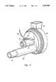
- FIG. 2is a perspective view of a blower from the water heater shown in FIG. 1.
- FIG. 3is a flow diagram reciting steps for production of a water heater.
- FIG. 1shows a water heater A including a water tank 10 supported in an upright position upon a cylindrical base 12.
- a combustion chamber 14is located at the bottom of tank 10 and defined in part by an upstanding steel cylindrical wall 16 having a steel exhaust gas exit tube 18 at its top.
- the water tank 10is surrounded by a layer of insulation 20 and a protective jacket 22 in the conventional manner.
- tank 10When water heater A is in use, with the burner inactivated, tank 10 normally contains stratified body of water 24 with the coldest water remaining in the bottom portion of the tank and the hottest water having risen to the top portion.
- the water to be heatedis introduced into water tank 10 through inlet piping 26 leading through bottom steel plate 17 of tank 10 and feeding water to an inlet water diffuser 30.
- Diffuser 30is a short, closed steel tube secured within tank 10 to bottom plate 17 thereof in a vertical orientation and having apertures 32 along one of its side surfaces through which water is introduced into the tank near its bottom.
- Heated wateris withdrawn from tank 10 through an outlet tube 34 which is fixed to a fitting 36 penetrating through bottom plate 17 of tank 10 and extends upwardly to the topmost region of tank 10.
- the top of outlet tube 34is open. Heated water passes through this top end opening into tube 34 and downwardly therethrough and out of tank 10 and into a hot water outlet 38.
- Inlet piping 26 and hot water outlet 38may be connected to the domestic water piping of the building in which the water heater A is disposed, thereby supplying hot water.
- Inlet piping 26 and hot water outlet 38may also be connected through appropriate valves to a heat exchanger in a space heating and ventilating system to provide heat for the building in accordance with the teachings of the aforementioned Cameron et al U.S. Pat. No. 4,766,883 and Jantana U.S. Pat. No. 4,451,410.
- Heatis provided to the body of water 24 from the heat of fuel combustion in combustion chamber 14.
- the equipment and method of supplying combustion gases to combustion chamber 14is described hereinafter with reference to a system using natural gas as the input energy source.
- Other fuelssuch as bottled propane gas and the like can be used with only slight adjustments to the system easily accomplished by those skilled in the art.
- Both hot water for domestic use and interior space heatingmay be provided by a single heater such as described herein and in the above mentioned U.S. Patents to Cameron et al and Jantana.
- an electric igniter 44 located within bottom region of combustion chamber 14is energized.
- the igniterquickly ignites a gas and fuel mixture introduced into combustion chamber 14 from a burner 50 located therein.
- a blower 52is energized and a fuel regulator 54 is turned on.
- Blower 52shown in FIG. 2 draws air from outside the water heater or the vehicle through air inlet tubing 56 into an air and fuel proportioner 58, as described in the above-mentioned Cameron et al U.S. Patent, where fuel is introduced to the air stream and some mixing occurs.
- the air and fuel mixtureis drawn into the body of blower 52 where it is pressurized and mixed further.
- a homogeneous air and fuel mixtureresults.
- This mixtureis burned in burner 50 to heat the water in tank 10.
- the combustion productsare vented through exhaust tubing 18 and out of water heater A. Exhaust tubing 18 winds through the water in tank 10 so that heat from the exhaust gases is transferred to the water.
- water heater Afurther includes a pump 21 adapted to circulate water 24 within tank 10.
- Pump 21is activated through a cable 31 extending from control box 42 which is responsive to a sensor 37 located in hot water outlet 38, which controls the activation of pump 21 in response to temperature or flow rate of the outgoing hot water.
- Pump 21is shown attached to jacket 22. However, it is often preferred to mount pump 21 below tank 10. With pump 21 mounted on the side of the tank 10, a lower tube 23 passes through a lower opening 25 and connects pump 21 to the body of water 24 inside tank 10. An upper tube 27 connects to pump 21, runs alongside jacket 22, passes through an upper opening 29 connecting pump 21 to the body of water 24 within tank 10. Upper tube 27 may also be positioned between tank 10 and jacket 22 or elsewhere.
- lower tube 23 and upper tube 27may both be arranged to penetrate through the bottom of tank 10.
- Lower tube 23terminates near the bottom of tank 10 and upper tube 27 terminates near the top of tank 10. The tubes and pump are thereby protected within the water heater structure.
- Pump 21is, as stated, connected to electrical control box 42 by line 31 and is activated whenever blower 52 is energized. This causes the water from tubes 23, 27 and 29 to remove and re-introduce water from and into tank 10 to circulate the tank water and minimize the likelihood that portions of the body of water 24 will be overheated. It is also possible for pump 21 to be activated in other ways such as when burner 50 is activated, when sensor 40 transmits a desired signal, when fuel regulator 54 is turned on, and the like. It will be appreciated that moving water from one point to another within a tank of water requires little energy and that only a small pump is needed.
- Blower 52is one in which the air and fuel intake is near the center portion of the blower body and the output is on the outer periphery of the blower.
- the pressurized and homogenized air and fuel mixture from blower 52is directed through output horn 60 of the blower and into the open bottom end of burner 50 within combustion chamber 14 through a circular burner inlet opening 62 centrally located in bottom plate 17 of tank 10.
- Blower 52is powered by a motor 53.
- Motor 53includes a speed control 101 in series with power supply line 105.
- blower 52is a variable speed blower wherein the resistance is varied by an adjusting screw 107. Varying the resistance in power line 105 varies the voltage supplied to motor 53 which in turn affects the speed of blower 52 and the amount of fuel supplied to burner 50.
- the speed of motor 53can be accurately set at the factory during assembly of water heater A as shown in FIG. 3 while monitoring the motor speed through an opening in the motor cover using a standard strobe timing light. In this manner, the heat generated by burner 50 can be accurately controlled so that the overheating and vaporization problems mentioned above are minimized.
- a high capacity pumpcould be used instead of pump 21 to rapidly circulate the water in tank 10 and partially compensate for the use of an unnecessarily large burner. Rapidly moving water spends less time in contact with the extreme heat of burner 50 and is, therefore, less likely to be overheated or vaporized.
- a pump sufficiently powerful to circulate water in this mannerhas increased energy requirements that decrease the efficiency of the system. Conversely, the rate at which burner 50 heats the water can be reduced to reduce overheating. This, however, results in a lower output of hot water.
- the small pump 21 preferred hereinmay be of any number of types and designs so long as it performs the task of adequately circulating water from and into tank 10 in the vicinity of the hot metal surfaces of combustion chamber 14 and exhaust tubing 18.
- the rate at which burner 50 heats water 24may be varied to correspond to the rate at which hot water is drawn from tank 10 through outlet tube 34 and hot water outlet 38.
- the blower speedmay be increased to provide more fuel and air to burner 50. This causes the incoming cold water to be heated rapidly. Because of the large amount of cold water entering tank 10 when hot water is being drawn off rapidly, overheating may not be a significant problem.
- the blower speedmay be decreased so that burner 50 heats the surrounding water more slowly.
- the proper blower speedis determined by monitoring either the flow rate of water passing through hot water outlet 38 or the temperature of the water, or both.
- a sensor 37 in hot water outlet 38provides information on temperature or flow rate to control box 42 through a cable 39. When the withdrawal rate of hot water is high, control box 42 signals speed control 101 through a cable 104 to increase the blower speed. When less hot water is being withdrawn, the blower speed is decreased to avoid overheating the water.
- sensor 37may be adapted to sense the temperature of the water in outlet 38. When the temperature sensed by sensor 37 falls below the water temperature which tank 10 is intended to provide, control box 42 signals speed control 101 to increase the blower speed and heat the water more rapidly.
Landscapes
- Engineering & Computer Science (AREA)
- Physics & Mathematics (AREA)
- Thermal Sciences (AREA)
- Chemical & Material Sciences (AREA)
- Combustion & Propulsion (AREA)
- Mechanical Engineering (AREA)
- General Engineering & Computer Science (AREA)
- Steam Or Hot-Water Central Heating Systems (AREA)
- Devices For Medical Bathing And Washing (AREA)
Abstract
Description
Claims (8)
Priority Applications (3)
| Application Number | Priority Date | Filing Date | Title |
|---|---|---|---|
| US08/166,729US5357907A (en) | 1993-12-14 | 1993-12-14 | Water heater with reduced localized overheating |
| CA002130962ACA2130962C (en) | 1993-12-14 | 1994-08-26 | Water heater with reduced localized overheating |
| US08/622,998USRE37240E1 (en) | 1993-12-14 | 1996-03-28 | Water heater with reduced localized overheating |
Applications Claiming Priority (1)
| Application Number | Priority Date | Filing Date | Title |
|---|---|---|---|
| US08/166,729US5357907A (en) | 1993-12-14 | 1993-12-14 | Water heater with reduced localized overheating |
Related Child Applications (1)
| Application Number | Title | Priority Date | Filing Date |
|---|---|---|---|
| US08/622,998ReissueUSRE37240E1 (en) | 1993-12-14 | 1996-03-28 | Water heater with reduced localized overheating |
Publications (1)
| Publication Number | Publication Date |
|---|---|
| US5357907Atrue US5357907A (en) | 1994-10-25 |
Family
ID=22604474
Family Applications (2)
| Application Number | Title | Priority Date | Filing Date |
|---|---|---|---|
| US08/166,729CeasedUS5357907A (en) | 1993-12-14 | 1993-12-14 | Water heater with reduced localized overheating |
| US08/622,998Expired - LifetimeUSRE37240E1 (en) | 1993-12-14 | 1996-03-28 | Water heater with reduced localized overheating |
Family Applications After (1)
| Application Number | Title | Priority Date | Filing Date |
|---|---|---|---|
| US08/622,998Expired - LifetimeUSRE37240E1 (en) | 1993-12-14 | 1996-03-28 | Water heater with reduced localized overheating |
Country Status (2)
| Country | Link |
|---|---|
| US (2) | US5357907A (en) |
| CA (1) | CA2130962C (en) |
Cited By (18)
| Publication number | Priority date | Publication date | Assignee | Title |
|---|---|---|---|---|
| US5537955A (en)* | 1994-10-24 | 1996-07-23 | Wu; Ya-Ching | Hot water heater |
| EP0831280A3 (en)* | 1996-09-20 | 1999-04-21 | Metaal Vries B.V. | Boiler |
| US6026801A (en)* | 1996-04-30 | 2000-02-22 | Barkan; Kenneth C. | Plug core heat exchanger |
| US6170440B1 (en) | 1998-05-13 | 2001-01-09 | Premark Feg L.L.C. | Gas fired booster |
| WO2001053750A1 (en)* | 2000-01-10 | 2001-07-26 | Lochinvar Corporation | Water heater with continuously variable air and fuel input |
| NL1014303C2 (en)* | 2000-02-07 | 2001-08-08 | Heatex Bv | Boiler. |
| US6553946B1 (en) | 2000-06-09 | 2003-04-29 | Roberrshaw Controls Company | Multi-function water heater control device |
| US6619951B2 (en) | 2000-01-10 | 2003-09-16 | Lochinvar Corporation | Burner |
| US6681723B1 (en) | 2003-02-12 | 2004-01-27 | Marvin Amendt | Hot water heater |
| US6694926B2 (en)* | 2000-01-10 | 2004-02-24 | Lochinvar Corporation | Water heater with continuously variable air and fuel input |
| US20050217612A1 (en)* | 2004-04-05 | 2005-10-06 | Aqua Max Pty Ltd | Water heater |
| US20080066694A1 (en)* | 2006-08-16 | 2008-03-20 | Aos Holding Company | Gas water heater |
| US20100043728A1 (en)* | 2008-08-25 | 2010-02-25 | Hongfei Ma | Water heater |
| AU2005201427B2 (en)* | 2004-04-05 | 2010-02-25 | Rheem Australia Pty Limited | Water heater |
| US20110214621A1 (en)* | 2010-03-08 | 2011-09-08 | Rheem Manufacturing Company | High efficiency gas-fired water heater |
| US20140199643A1 (en)* | 2013-01-16 | 2014-07-17 | A. O. Smith Corporation | Modulating Burner |
| US20150090200A1 (en)* | 2012-03-01 | 2015-04-02 | A. O. Smith Corporation | Low-noise, gas-type, instantaneous water heater |
| US10247446B2 (en) | 2007-03-09 | 2019-04-02 | Lochinvar, Llc | Control system for modulating water heater |
Families Citing this family (10)
| Publication number | Priority date | Publication date | Assignee | Title |
|---|---|---|---|---|
| US7695275B2 (en)* | 2004-06-02 | 2010-04-13 | Fuel Management, Inc. | Air:fluid distribution system and method |
| US7117825B2 (en)* | 2004-06-30 | 2006-10-10 | Synapse, Inc. | System and method for preventing overheating of water within a water heater tank |
| US7418960B2 (en) | 2004-09-30 | 2008-09-02 | Premark Feg Llc | Steam cooker and related superheater |
| US7353821B2 (en)* | 2004-11-24 | 2008-04-08 | Premark Feg L.L.C. | Steam oven system having steam generator with controlled fill process |
| US7458341B2 (en)* | 2005-08-01 | 2008-12-02 | Bradford White Corporation | Water heater with convoluted flue tube |
| US7836856B2 (en)* | 2007-12-13 | 2010-11-23 | Bock Water Heaters, Inc. | Water heater with condensing flue |
| US8126320B2 (en)* | 2008-03-05 | 2012-02-28 | Robertshaw Controls Company | Methods for preventing a dry fire condition and a water heater incorporating same |
| US20120048259A1 (en)* | 2010-08-26 | 2012-03-01 | Wagner & Co., Solartechnik GmbH | Solar installation |
| US8763564B2 (en) | 2011-11-08 | 2014-07-01 | A. O. Smith Corporation | Water heater and method of operating |
| US10281351B2 (en)* | 2012-11-19 | 2019-05-07 | A. O. Smith Corporation | Water heater and pressure probe for a water heater |
Citations (3)
| Publication number | Priority date | Publication date | Assignee | Title |
|---|---|---|---|---|
| US903931A (en)* | 1908-05-12 | 1908-11-17 | William P Wiemann | Device for purifying water in steam-boilers. |
| US5022352A (en)* | 1990-05-31 | 1991-06-11 | Mor-Flo Industries, Inc. | Burner for forced draft controlled mixture heating system using a closed combustion chamber |
| US5179914A (en)* | 1991-09-30 | 1993-01-19 | Mor-Flo Industries, Inc. | Forced draft water heater with an improved tank structure and a method for making water heaters |
Family Cites Families (12)
| Publication number | Priority date | Publication date | Assignee | Title |
|---|---|---|---|---|
| US4201518A (en)* | 1978-05-12 | 1980-05-06 | Alden Stevenson | Recirculating fluid pump control system |
| US4869232A (en)* | 1979-12-10 | 1989-09-26 | Narang Rajendra K | Oil and gas water heater |
| US4549525A (en)* | 1979-12-10 | 1985-10-29 | Narang Rajendra K | Oil and gas water heater |
| US4498622A (en)* | 1983-05-23 | 1985-02-12 | Borg-Warner Corporation | Quick recovery heat pump water heater |
| US4641631A (en)* | 1983-07-20 | 1987-02-10 | Columbia Gas System Service Corporation | Apparatus and method for burning a combustible gas, and a heat exchanger for use in this apparatus |
| US4541410A (en)* | 1983-07-20 | 1985-09-17 | Columbia Gas System Service Corporation | Apparatus and method for burning a combustible gas, and a heat exchanger for use in this apparatus |
| US4750472A (en)* | 1984-05-24 | 1988-06-14 | Fazekas Dale J | Control means and process for domestic hot water re-circulating system |
| US4628902A (en)* | 1985-06-03 | 1986-12-16 | Comber Cornelius J | Hot water distribution system |
| US4766883A (en)* | 1986-02-26 | 1988-08-30 | Mor-Flo Industries, Inc. | Forced draft controlled mixture heating system using a closed combustion chamber |
| US4790291A (en) | 1987-05-07 | 1988-12-13 | A.O. Smith Corporation | Sediment agitating apparatus for water heater |
| US4790289A (en)* | 1987-05-07 | 1988-12-13 | A. O. Smith Corporation | Sediment agitating apparatus for water heater |
| US5347956A (en)* | 1993-05-05 | 1994-09-20 | Aos Holding Company | Water heater with integral mixing valve |
- 1993
- 1993-12-14USUS08/166,729patent/US5357907A/ennot_activeCeased
- 1994
- 1994-08-26CACA002130962Apatent/CA2130962C/ennot_activeExpired - Fee Related
- 1996
- 1996-03-28USUS08/622,998patent/USRE37240E1/ennot_activeExpired - Lifetime
Patent Citations (3)
| Publication number | Priority date | Publication date | Assignee | Title |
|---|---|---|---|---|
| US903931A (en)* | 1908-05-12 | 1908-11-17 | William P Wiemann | Device for purifying water in steam-boilers. |
| US5022352A (en)* | 1990-05-31 | 1991-06-11 | Mor-Flo Industries, Inc. | Burner for forced draft controlled mixture heating system using a closed combustion chamber |
| US5179914A (en)* | 1991-09-30 | 1993-01-19 | Mor-Flo Industries, Inc. | Forced draft water heater with an improved tank structure and a method for making water heaters |
Cited By (26)
| Publication number | Priority date | Publication date | Assignee | Title |
|---|---|---|---|---|
| US5537955A (en)* | 1994-10-24 | 1996-07-23 | Wu; Ya-Ching | Hot water heater |
| US6026801A (en)* | 1996-04-30 | 2000-02-22 | Barkan; Kenneth C. | Plug core heat exchanger |
| EP0831280A3 (en)* | 1996-09-20 | 1999-04-21 | Metaal Vries B.V. | Boiler |
| US6170440B1 (en) | 1998-05-13 | 2001-01-09 | Premark Feg L.L.C. | Gas fired booster |
| US6694926B2 (en)* | 2000-01-10 | 2004-02-24 | Lochinvar Corporation | Water heater with continuously variable air and fuel input |
| US6619951B2 (en) | 2000-01-10 | 2003-09-16 | Lochinvar Corporation | Burner |
| WO2001053750A1 (en)* | 2000-01-10 | 2001-07-26 | Lochinvar Corporation | Water heater with continuously variable air and fuel input |
| NL1014303C2 (en)* | 2000-02-07 | 2001-08-08 | Heatex Bv | Boiler. |
| US6553946B1 (en) | 2000-06-09 | 2003-04-29 | Roberrshaw Controls Company | Multi-function water heater control device |
| US6681723B1 (en) | 2003-02-12 | 2004-01-27 | Marvin Amendt | Hot water heater |
| AU2005201427B2 (en)* | 2004-04-05 | 2010-02-25 | Rheem Australia Pty Limited | Water heater |
| US20050217612A1 (en)* | 2004-04-05 | 2005-10-06 | Aqua Max Pty Ltd | Water heater |
| US7337753B2 (en)* | 2004-04-05 | 2008-03-04 | Aqua Max Pty Ltd. | Water heater |
| US20080066694A1 (en)* | 2006-08-16 | 2008-03-20 | Aos Holding Company | Gas water heater |
| US7634977B2 (en) | 2006-08-16 | 2009-12-22 | Aos Holding Company | Gas water heater |
| US10247446B2 (en) | 2007-03-09 | 2019-04-02 | Lochinvar, Llc | Control system for modulating water heater |
| US10955169B2 (en) | 2007-03-09 | 2021-03-23 | Lochinvar, Llc | Control system for modulating water heater |
| US20100043728A1 (en)* | 2008-08-25 | 2010-02-25 | Hongfei Ma | Water heater |
| US8161918B2 (en) | 2008-08-25 | 2012-04-24 | Aos Holding Company | Water heater |
| US20110214621A1 (en)* | 2010-03-08 | 2011-09-08 | Rheem Manufacturing Company | High efficiency gas-fired water heater |
| US9004018B2 (en)* | 2010-03-08 | 2015-04-14 | Rheem Manufacturing Company | High efficiency gas-fired water heater |
| US20150090200A1 (en)* | 2012-03-01 | 2015-04-02 | A. O. Smith Corporation | Low-noise, gas-type, instantaneous water heater |
| US9441857B2 (en)* | 2012-03-01 | 2016-09-13 | A. O. Smith Corporation | Low-noise, gas-type, instantaneous water heater |
| US20140199643A1 (en)* | 2013-01-16 | 2014-07-17 | A. O. Smith Corporation | Modulating Burner |
| US9464805B2 (en)* | 2013-01-16 | 2016-10-11 | Lochinvar, Llc | Modulating burner |
| US10208953B2 (en) | 2013-01-16 | 2019-02-19 | A. O. Smith Corporation | Modulating burner |
Also Published As
| Publication number | Publication date |
|---|---|
| USRE37240E1 (en) | 2001-06-26 |
| CA2130962A1 (en) | 1995-06-15 |
| CA2130962C (en) | 2004-04-20 |
Similar Documents
| Publication | Publication Date | Title |
|---|---|---|
| US5357907A (en) | Water heater with reduced localized overheating | |
| CA2002488C (en) | Forced draft direct vent system for a water heater | |
| AU744207B2 (en) | Power vent water heater with electronic control system | |
| US5022352A (en) | Burner for forced draft controlled mixture heating system using a closed combustion chamber | |
| WO1996006309A3 (en) | Combination water heating and space heating apparatus | |
| US3847350A (en) | Vehicle heating unit | |
| US5085579A (en) | Powered chamber combustion system and burner therefor | |
| US6345769B2 (en) | Water heating apparatus with sensible and latent heat recovery | |
| US6394042B1 (en) | Gas fired tube and shell heat exchanger | |
| US2216809A (en) | Heater and thermo control therefor | |
| DK162952B (en) | APPLIANCE FOR COMBUSTION OF A FLAMMABLE GAS | |
| US4406402A (en) | Flue heat recovery system | |
| US4360003A (en) | Wood burning hot water heater | |
| US3072176A (en) | Heater | |
| US2501627A (en) | Thermoelectric self-controlling combustion heating system | |
| US5888060A (en) | Method and device to increase combustion efficiency heating appliances | |
| MX2014010325A (en) | Gas burner system for gas-powered cooking devices. | |
| US3404674A (en) | Heat exchange apparatus for the employment of flue gas heat | |
| US2625150A (en) | Space heating hot-air furnace for house trailers and the like | |
| US2252784A (en) | Heating and air conditioning unit | |
| US20040149742A1 (en) | System to heat liquids | |
| US2525400A (en) | Air heater with solid fuel and fluid fuel burning furnaces arranged in tandem | |
| US4773390A (en) | Demand hot water system | |
| US1994184A (en) | Warm air heating system | |
| EP0275568A1 (en) | Hot water apparatus operating through gas combustion and provided with an air supply fan and a modulating gas/air control |
Legal Events
| Date | Code | Title | Description |
|---|---|---|---|
| AS | Assignment | Owner name:SABH (U.S.) WATER HEATER GROUP, INC., PENNSYLVANIA Free format text:ASSIGNMENT OF ASSIGNORS INTEREST;ASSIGNORS:MOORE, H. JACK, JR.;GIDANIAN, BIJAN;REEL/FRAME:006808/0370 Effective date:19931101 | |
| STCF | Information on status: patent grant | Free format text:PATENTED CASE | |
| AS | Assignment | Owner name:SOUTHCORP WATER HEATERS USA, INC., GEORGIA Free format text:CHANGE OF NAME;ASSIGNOR:SABH (U.S.) WATER HEATER GROUP, INC.;REEL/FRAME:007838/0315 Effective date:19931125 | |
| RF | Reissue application filed | Effective date:19960328 | |
| FPAY | Fee payment | Year of fee payment:4 | |
| AS | Assignment | Owner name:AMERICAN WATER HEATERS-WEST, INC., TENNESSEE Free format text:MERGER;ASSIGNOR:SOUTHCORP WATER HEATERS USA, INC.;REEL/FRAME:012075/0792 Effective date:19991219 Owner name:AMERICAN WATER HEATER COMPANY, TENNESSEE Free format text:MERGER;ASSIGNOR:AMERICAN WATER HEATERS-WEST, INC.;REEL/FRAME:012083/0001 Effective date:19961219 | |
| FEPP | Fee payment procedure | Free format text:PAYOR NUMBER ASSIGNED (ORIGINAL EVENT CODE: ASPN); ENTITY STATUS OF PATENT OWNER: LARGE ENTITY | |
| AS | Assignment | Owner name:FLEET CAPITAL CORPORATION, ILLINOIS Free format text:ASSIGNMENT OF ASSIGNORS INTEREST;ASSIGNOR:AMERICAN WATER HEATER COMPANY;REEL/FRAME:013081/0351 Effective date:20020619 | |
| FEPP | Fee payment procedure | Free format text:PAYER NUMBER DE-ASSIGNED (ORIGINAL EVENT CODE: RMPN); ENTITY STATUS OF PATENT OWNER: LARGE ENTITY Free format text:PAYOR NUMBER ASSIGNED (ORIGINAL EVENT CODE: ASPN); ENTITY STATUS OF PATENT OWNER: LARGE ENTITY |