US5356356A - Recumbent total body exerciser - Google Patents
Recumbent total body exerciserDownload PDFInfo
- Publication number
- US5356356A US5356356AUS08/071,188US7118893AUS5356356AUS 5356356 AUS5356356 AUS 5356356AUS 7118893 AUS7118893 AUS 7118893AUS 5356356 AUS5356356 AUS 5356356A
- Authority
- US
- United States
- Prior art keywords
- arm
- seat
- set forth
- leg
- assemblies
- Prior art date
- Legal status (The legal status is an assumption and is not a legal conclusion. Google has not performed a legal analysis and makes no representation as to the accuracy of the status listed.)
- Expired - Lifetime
Links
- 230000000712assemblyEffects0.000claimsabstractdescription50
- 238000000429assemblyMethods0.000claimsabstractdescription50
- 230000003750conditioning effectEffects0.000claimsabstractdescription10
- 230000002526effect on cardiovascular systemEffects0.000claimsabstractdescription4
- 238000000554physical therapyMethods0.000claimsdescription12
- 238000009207exercise therapyMethods0.000claimsdescription2
- 238000007664blowingMethods0.000claims1
- 230000008261resistance mechanismEffects0.000abstractdescription5
- 230000007246mechanismEffects0.000description13
- 230000008901benefitEffects0.000description5
- 210000003205muscleAnatomy0.000description5
- 238000002560therapeutic procedureMethods0.000description5
- 230000006378damageEffects0.000description3
- 230000003247decreasing effectEffects0.000description3
- 208000027418Wounds and injuryDiseases0.000description2
- 230000009194climbingEffects0.000description2
- 208000014674injuryDiseases0.000description2
- 239000000463materialSubstances0.000description2
- 230000001360synchronised effectEffects0.000description2
- 239000004677NylonSubstances0.000description1
- 229910000831SteelInorganic materials0.000description1
- 230000036772blood pressureEffects0.000description1
- 230000007407health benefitEffects0.000description1
- 208000018883loss of balanceDiseases0.000description1
- 238000012423maintenanceMethods0.000description1
- 238000000034methodMethods0.000description1
- 229920001778nylonPolymers0.000description1
- 238000011084recoveryMethods0.000description1
- 230000004044responseEffects0.000description1
- 230000000717retained effectEffects0.000description1
- 238000005096rolling processMethods0.000description1
- 239000010959steelSubstances0.000description1
- 238000005728strengtheningMethods0.000description1
Images


Classifications
- A—HUMAN NECESSITIES
- A63—SPORTS; GAMES; AMUSEMENTS
- A63B—APPARATUS FOR PHYSICAL TRAINING, GYMNASTICS, SWIMMING, CLIMBING, OR FENCING; BALL GAMES; TRAINING EQUIPMENT
- A63B21/00—Exercising apparatus for developing or strengthening the muscles or joints of the body by working against a counterforce, with or without measuring devices
- A63B21/15—Arrangements for force transmissions
- A63B21/157—Ratchet-wheel links; Overrunning clutches; One-way clutches
- A—HUMAN NECESSITIES
- A63—SPORTS; GAMES; AMUSEMENTS
- A63B—APPARATUS FOR PHYSICAL TRAINING, GYMNASTICS, SWIMMING, CLIMBING, OR FENCING; BALL GAMES; TRAINING EQUIPMENT
- A63B22/00—Exercising apparatus specially adapted for conditioning the cardio-vascular system, for training agility or co-ordination of movements
- A63B22/0002—Exercising apparatus specially adapted for conditioning the cardio-vascular system, for training agility or co-ordination of movements involving an exercising of arms
- A63B22/001—Exercising apparatus specially adapted for conditioning the cardio-vascular system, for training agility or co-ordination of movements involving an exercising of arms by simultaneously exercising arms and legs, e.g. diagonally in anti-phase
- A—HUMAN NECESSITIES
- A63—SPORTS; GAMES; AMUSEMENTS
- A63B—APPARATUS FOR PHYSICAL TRAINING, GYMNASTICS, SWIMMING, CLIMBING, OR FENCING; BALL GAMES; TRAINING EQUIPMENT
- A63B22/00—Exercising apparatus specially adapted for conditioning the cardio-vascular system, for training agility or co-ordination of movements
- A63B22/0048—Exercising apparatus specially adapted for conditioning the cardio-vascular system, for training agility or co-ordination of movements with cantilevered support elements pivoting about an axis
- A63B22/0056—Exercising apparatus specially adapted for conditioning the cardio-vascular system, for training agility or co-ordination of movements with cantilevered support elements pivoting about an axis the pivoting movement being in a vertical plane, e.g. steppers with a horizontal axis
- A—HUMAN NECESSITIES
- A63—SPORTS; GAMES; AMUSEMENTS
- A63B—APPARATUS FOR PHYSICAL TRAINING, GYMNASTICS, SWIMMING, CLIMBING, OR FENCING; BALL GAMES; TRAINING EQUIPMENT
- A63B21/00—Exercising apparatus for developing or strengthening the muscles or joints of the body by working against a counterforce, with or without measuring devices
- A63B21/008—Exercising apparatus for developing or strengthening the muscles or joints of the body by working against a counterforce, with or without measuring devices using hydraulic or pneumatic force-resisters
- A63B21/0085—Exercising apparatus for developing or strengthening the muscles or joints of the body by working against a counterforce, with or without measuring devices using hydraulic or pneumatic force-resisters using pneumatic force-resisters
- A63B21/0088—Exercising apparatus for developing or strengthening the muscles or joints of the body by working against a counterforce, with or without measuring devices using hydraulic or pneumatic force-resisters using pneumatic force-resisters by moving the surrounding air
- A—HUMAN NECESSITIES
- A63—SPORTS; GAMES; AMUSEMENTS
- A63B—APPARATUS FOR PHYSICAL TRAINING, GYMNASTICS, SWIMMING, CLIMBING, OR FENCING; BALL GAMES; TRAINING EQUIPMENT
- A63B21/00—Exercising apparatus for developing or strengthening the muscles or joints of the body by working against a counterforce, with or without measuring devices
- A63B21/012—Exercising apparatus for developing or strengthening the muscles or joints of the body by working against a counterforce, with or without measuring devices using frictional force-resisters
- A63B21/015—Exercising apparatus for developing or strengthening the muscles or joints of the body by working against a counterforce, with or without measuring devices using frictional force-resisters including rotating or oscillating elements rubbing against fixed elements
- A—HUMAN NECESSITIES
- A63—SPORTS; GAMES; AMUSEMENTS
- A63B—APPARATUS FOR PHYSICAL TRAINING, GYMNASTICS, SWIMMING, CLIMBING, OR FENCING; BALL GAMES; TRAINING EQUIPMENT
- A63B21/00—Exercising apparatus for developing or strengthening the muscles or joints of the body by working against a counterforce, with or without measuring devices
- A63B21/22—Resisting devices with rotary bodies
- A63B21/225—Resisting devices with rotary bodies with flywheels
- A—HUMAN NECESSITIES
- A63—SPORTS; GAMES; AMUSEMENTS
- A63B—APPARATUS FOR PHYSICAL TRAINING, GYMNASTICS, SWIMMING, CLIMBING, OR FENCING; BALL GAMES; TRAINING EQUIPMENT
- A63B2208/00—Characteristics or parameters related to the user or player
- A63B2208/02—Characteristics or parameters related to the user or player posture
- A63B2208/0228—Sitting on the buttocks
- A63B2208/0238—Sitting on the buttocks with stretched legs, like on a bed
- A—HUMAN NECESSITIES
- A63—SPORTS; GAMES; AMUSEMENTS
- A63B—APPARATUS FOR PHYSICAL TRAINING, GYMNASTICS, SWIMMING, CLIMBING, OR FENCING; BALL GAMES; TRAINING EQUIPMENT
- A63B2220/00—Measuring of physical parameters relating to sporting activity
- A63B2220/70—Measuring or simulating ambient conditions, e.g. weather, terrain or surface conditions
- A63B2220/76—Wind conditions
- A—HUMAN NECESSITIES
- A63—SPORTS; GAMES; AMUSEMENTS
- A63B—APPARATUS FOR PHYSICAL TRAINING, GYMNASTICS, SWIMMING, CLIMBING, OR FENCING; BALL GAMES; TRAINING EQUIPMENT
- A63B2225/00—Miscellaneous features of sport apparatus, devices or equipment
- A63B2225/09—Adjustable dimensions
Definitions
- This inventiongenerally relates to equipment for physical therapy and/or general exercise. More particularly, this invention relates to a recumbent exercise machine which provides for the exercising and strengthening of major muscle groups in addition to cardiovascular conditioning. In so doing, the present invention includes lower body exercising coordinated with upper body exercising.
- steppersstepping machines
- stationary bicyclesstepping machines
- steppersinclude a pair of pedals which move up and down, thereby simulating the climbing of steps, in response to the weight and physical effort of the patient or exerciser (hereinafter "user").
- the pedalsare connected to a mechanism which applies a resistance or load. This resistance is often adjustable so that the stepper can accommodate users of various levels of physical conditioning and ability.
- steppersOne limitation of steppers is that the user is typically required to stand during the exercise. Since the user is in an upright position, a significant amount of balance and coordination on the part of the user is required. Because of the decreased mobility and coordination, this may prevent a patient undergoing physical therapy from using the stepper.
- a related limitation of the stepperis that it requires continuous close supervision when being used by a person undergoing physical rehabilitation. Close supervision by a physical therapist or assistant is required to ensure that the patient does not collapse or otherwise lose balance and fall from the stepper resulting in an injury.
- a further limitation of the stepperis its lack of exercise or conditioning of the upper body of the user. Finally, steppers may elevate the heart rate and the blood pressure too quickly for unconditioned and elderly patents, potentially causing harm.
- stationary bicyclesOne limitation of stationary bicycles is that the seat is typically a narrow saddle seat positioned above a pair of rotatable pedals having a fixed range of motion. The rotation of the pedals is resisted by a brake or other resistance mechanism. The user is required to lean forward to hold onto a set of handles, which may be stationary or movable. In order to use a stationary bicycle, the user must be capable of climbing up onto the seat and must possess sufficient strength, balance and coordination to maintain themselves on the narrow seat while pedaling over a fixed range of motion and manipulating the handles if they are of the moveable variety. Often the elderly, overweight or physical therapy patient cannot use a stationary bike because of the above requirements and further because they require constant supervision by the physical therapist to prevent possible injury to the patient upon collapse or loss of balance.
- the apparatusshould provide a high degree of stability and safety to the user so that the user can manipulate the machine without constant attention or supervision. Additionally, the apparatus should be adjustable to accommodate users of the significantly different sizes and physical conditions while still being comfortable.
- a further object of this inventionis to provide a recumbent apparatus which can be easily mounted and dismounted by a user having a limited amount of mobility, with or without the assistance of another person.
- the present inventionalso has as one of its objects providing an apparatus which uses a stepping or oscillating arcuate motion to provide a lower body workout or therapy.
- a further object of the inventionis to provide an apparatus which uses an oscillating arcuate motion to provide an upper body workout or therapy.
- Another object of this inventionis to provide an apparatus which is familiar to use and which simulates the coordinated arm and leg movements used during walking or running.
- the inventionalso has as one of its objects providing upper body exercise which is diagonally coordinated with lower body exercise.
- Still another object of the present inventionis to provide a physical therapy and exercise apparatus which is easy to use, has adjustable resistance levels, is durable and which is relatively inexpensive to produce.
- the present inventionprovides for a recumbent total body exercise apparatus.
- the apparatusincludes pedals which undergo an oscillating or stepping motion.
- the pedalsare contralaterally synchronized with handles that also undergo a oscillating motion providing the user with a total body conditioning workout.
- the present inventionutilizes a recumbent seat which is horizontally displaced from the pedals.
- the seatitself is a full bucket style seat, including a seat cushion an a seat back, positioned at a normal chair height. This provides a safe, stable and familiar seating position for the user.
- the stability of the seatassures the physical therapist or assistant that the patient can use the apparatus with only moderate supervision thereby freeing the physical therapist to attend to other patients or other duties.
- the exerciser of the present inventionis also provided with an open center region, immediately before the seat, having a low profile step-through design offering easy ingress and egress to the user.
- a patient with low mobilityis not required to climb up onto the apparatus or raise a leg over a high center portion of a frame. Rather, the user can easily step over a low center height portion of the apparatus' frame and sit down as would be normally done in a chair.
- the position of the chair relative to the pedalscan be adjusted, as well as the length of the handles relative to the chair, for the size of the particular user.
- the relationship and geometry of the chair, the pedals, the handles, and the position of the pivot for the handles and pedalsis such that the movement of the user's arms and legs will be maintained in a correct biomechanical relationship or form. The maintenance of proper form ensures efficient conditioning in addition to a comfortable exercising or therapy position.
- the pedals and handlesundergo their coordinated movement against a resistance force provided by one of the variety of known resistance mechanisms.
- the level of resistance provided by the resistance mechanismis adjustable to accommodate users of all fitness levels.
- the resistance mechanismmay be electronically controlled to produce a resistance pattern representing a therapy or workout cycle of varied physical difficulty.
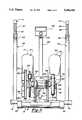
- FIG. 1is a side elevational view with portions broken away of an apparatus embodying the principles of the present invention
- FIG. 2is a bottom view with portions broken away of the apparatus shown in FIG. 1;
- FIG. 3is a rear view of the apparatus seen in FIG. 1 having portions removed therefrom for clarity;
- FIG. 4is a diagrammatic illustration of the present invention showing an air blower feature thereof.
- FIG. 5is a side elevational view of the seat assembly utilized with the present invention.
- FIG. 1an apparatus embodying the principles of the present invention is illustrated in FIG. 1 and generally designated at 10.
- the apparatus 10is a physical therapy or exercise device which could be referred to as a total body, recumbent stepping machine.
- the apparatus 10is a total body exerciser since it strengthens or rehabilitates all of the major muscle groups while also providing for effective cardiovascular conditioning.
- the apparatusis recumbent since the patient or user is generally in a reclined position when it is being used.
- the apparatus 10can be referred to as a stepper since it exercises the legs of the user through an oscillating or reciprocating movement of the pedals and through the offering resistance to pushing of the pedals. While pushing resistance exercises the legs and lower body of the user, the exercising of the upper body and arms is through pulling or pushing resistance offered through a pair of handles.
- the apparatus or exercise machine 10 of the present inventionis comprised of a frame 12 which includes a front support 14 and a rear support 16 which provide the machine 10 with a high degree of stability during use.
- the frame 12also includes a central portion 18, extending between the front and rear supports 14 and 16, which generally defines a casing that partially encloses and supports the resistance assembly as further discussed below.
- Some of the components of the resistance assemblyare supported on the central portion 18 of the frame 12 and are enclosed within a housing 26 that prevents their inadvertent contact with the patient or the patient's clothing during use of the machine 10.
- the frame 12is made from steel in various stock forms such as plate stock, angle stock or tubular stock.
- the tubular rear support 16defines a T-section with the central portion 18 and the front support 14 which are made of plate stock.
- the front support 14is spaced from the rear support 16 generally along a central axis 24 which bisects the rear support 16.
- Rolling wheels 20are provided on the ends of the rear support 16 for contact with the floor supporting the exercise machine 10.
- the flooris generally designated at 22 in FIG. 4.
- the seat 28is generally of the full bucket variety and is padded for the comfort of the user.
- the seat 28is positioned so that the height of the seat cushion 30 approximates the height of a standard chair thereby inherently increasing the user's familiarity with the machine 10.
- the slope along the top of the housing 26allows the height of the seat 28 to be lowered as it is adjusted forward for shorter users and raised as it is adjusted rearward for taller users.
- Laterally outboard of the seat cushion 30are a pair of stationary grab bars 34 having padded grips 36 on their ends. The grab bars 34 are provided so that the user has an alternate holding position when upper body conditioning is not desired.
- the seat 28can be adjustably positioned axially along the central axis 24. This is accomplished through an adjustment mechanism 38 of the rack and slider variety.
- the adjustment mechanism 38includes a stationary rack 40 having a toothed slot defined along its length.
- a movable rack 44secured to the underside of the seat 28, is mounted for sliding movement relative to the stationary rack 40.
- a lever arm 46is pivotally mounted to the seat 28 and includes a pin 48 biased by a spring 49 so as to engage the serrated portions of the toothed slot 42. By lifting upwardly on the lever arm 46, the pin 48 is disengaged from a serration in the toothed slot 42 enabling the seat 28 and movable rack 44 to slide along the central axis 24.
- the adjustment mechanism 38is also provided with a retaining block 50 having a slot 52 defined therein.
- the block 50 and slot 52prevent the pin 48 from inadvertently becoming disengaged from a serration of the toothed slot 42.
- the retaining block 50is movable with the movable rack 44 and its slot 52 corresponds with the location of the pin 48. While one specific variety of adjustment mechanism 38 has been specifically described in detail, it will be appreciated that numerous other types of adjustment mechanisms could be substituted for the mechanism 38 illustrated and discussed above. Alternate mechanisms are therefore deemed to be within the purview of this invention.
- a pair of arm assemblies 54 and 55 and a pair of leg assemblies 56 and 57Located forward of the seat 28 are a pair of arm assemblies 54 and 55 and a pair of leg assemblies 56 and 57, all of which are configured to undergo oscillating or reciprocating movement about a common pivot axis 58.
- the pivot axis 58extends generally parallel to the rear support 14 and is located so as to generally correspond with the front support 16 at a low height relative to the seat 28 and close to the floor 22.
- the arm assemblies 54 and 55include lower levers 60 and 61 which extend forward and upward from the pivot axis to elbows 62 and 63. Thereafter, the arm assemblies 54 and 55 extend rearward and upward toward the seat 28 along upper extensions 64 and 65. Handles 66 and 67 are slidable received in the upper extensions 64 and 65 and are provided with key-way slots 53 so as to prevent their rotation relative to the upper extensions 64 and 65. The handles 66 and 67 can be adjusted in length and for this reason locking levers 68 and 69 are provided on the upper extensions 64 and 65 to secure them at the desired length. The ends of the handles 66 and 67 are generally bent upward and inward relative to the remainder of the handles 66 and 67 and are provided with padded grips 70 and 71 for the user's comfort.
- the leg assemblies 56 and 57similarly extend forward and upward from the pivot axis 58 along levers 72 and 73.
- the levers 72 and 73include elbow portions 74 and 75 at their upper ends which bend back in a direction toward the seat 28 and to which are attached pedals 76 and 77.
- the pedalsare preferably secured to the levers 72 and 73 in a pivotable manner, but could alternatively be rigidly secured thereto.
- the pedals 76 and 77are provided with heel cups 78 and 79 at their lower ends so that the foot of a user will not inadvertently slip off of the deck portion of the pedals 76 and 77.
- the geometry and orientation of the seat 28, handles 66 and 67, the pedals 76 and 77 and the pivot axis 58are set relative to one another so that, regardless of the size of the person using the machine 10, once properly adjusted, the resulting movement and form during upper and lower body conditioning is biomechanically correct and efficient. This is particularly important in the physical therapy setting where the proper form can result in quicker and safer recovery and rehabilitation.
- the arm assemblies 54 and 55are connected to the leg assemblies 56 and 57 for contralateral movement about the pivot axis 58. To accomplish this, a series of coaxial sleeves are assembled along the pivot axis 58. As seen in FIG. 2, the lower levers 60 and 61 of the arm assemblies 54 and 55 terminate in transverse sleeves 80 and 81 which are coaxial with the pivot axis 58. Similarly, the levers 72 and 73 of the leg assemblies terminate in transverse sleeves 86 and 87 coaxial with the pivot axis 58 and inboard of the arm sleeves 80 and 81.
- the arm sleeves 80 and 81each include a reduced diameter shaft 82 and 83 which extends inboard along the pivot axis 58.
- Bushings 94 and 95support the shafts 82 and 83 on the front support 14 and the frame 12.
- Each shaft 82 and 83is connected by bolts (not shown) to a U-shaped linkage 84 and 85.
- the U-shaped linkages 84 and 85are generally oriented in a horizontal plane and are generally offset from one another so that the legs of one U-shape linkage 84 are alongside or overlap those of the other linkage 85.
- the open portions of the U-shaped linkages 84 and 85face toward one another. As seen in FIG.
- the shaft 82 of the right side arm assembly 54extends through the outboard leg of the right side U-shaped linkage 85 before terminating in a rigid connection to the leg of left side U-shaped linkage 84.
- the shaft 83 of the left side arm assembly 55extends through an aperture in the outboard leg of the left side U-shaped linkage 84 before terminating in a rigid mounting to the leg of the right side U-shaped linkage 85.
- the pedals 76 and 77are connected for contralateral movement with the handles 67 and 66.
- the leg levers 72 and 73terminate in transverse sleeves 86 and 87 that are coaxial with the pivot axis 58.
- the sleeves 86 and 87are respectively mounted on the reduced diameter shafts 82 and 83 for relative pivotal movement and are separated from the arm sleeves 80 and 81 by the bushings 94 and 95 mentioned above.
- the sleeve 86 of the right leg assembly 56is rigidly secured to the outboard leg of the right side U-shaped linkage 85 which, as discussed above, is coupled to the left arm lever 55.
- the sleeve 87 of the left leg assembly 57is rigidly secured to the outboard leg of the left side U-shaped linkage 84 so that it will rotate with the right arm lever 54. While one specific embodiment is illustrated for contralaterally coordinating the movement of the arm and leg assemblies 54, 55, 56 and 57, it should be understood that additional methods for coordinating this movement could also be readily provided and are deemed to be within the purview of this invention.
- the range of pivotal movement which the arm and leg assemblies 54, 55, 56 and 57 may undergois limited by bumpers 142.
- the bumpers 142are positioned in the front support 14 so as to engage the U-shaped linkages 84 and 85 and limit the forward and rearward movement thereby preventing further rotation about the pivoting axis 58. By increasing or decreasing the size or height of the bumpers 142, the actual range of movement of the arm and leg assemblies 54, 55, 56 and 57 can be adjusted.
- the length and geometry of the arm and leg assemblies 54, 55, 56 and 57are provided so that the pedals 76 and 77 undergo a range of motion or "step" of approximately eleven (11) inches while the handles 66 and 67 undergo a twenty (20) to twenty-seven (27) inch range of motion, depending on the adjusted length of handles 66 and 67. Because this movement is about the pivoting axis 58, the movement of the pedals 76 and 77 and the handles 66 and 67 is arcuate.
- the movement of one set of arm and leg assemblies 54 and 57is tied to the movement of the other set of arm and leg assemblies 55 and 56 so that movement of one induces a counter movement in the other. In other words, as one set moves forward the other set moves backward.
- a pair of yokes 88 and 89provided outboard of the U-shaped linkages 84 and 85, are secured to the U-shaped linkages 84 and 85 by fasteners such as bolts (not shown) so that they move with the linkages 84 and 85.
- the yokes 88 and 89are connected together by a front or forward extending cable 90.
- the cable 90extends forward from one yoke 88 and is looped around a pulley 92 which returns it for securement to the other yoke 89.
- the pulleyis mounted to the frame 12 so that it will rotate about an axis generally perpendicular to the central axis 24.
- a cable adjustment mechanismcan be provided on the yokes 88 and 89 or on the pulley 92 so that the tension of the cable 90 can be adjusted as needed for proper operation of the machine 10.
- a brake or resistance assemblyis coupled to the yokes 88 and 89. While only one embodiment of the resistance assembly is being described in detail, it will become apparent that a number of known resistance assemblies could be readily employed with the present invention. One such resistance assembly would be an eddy current resistance assembly presently used in other exercise machines.
- a pair of interconnected chains 96 and 97are used to couple the yokes 88 and 89 to the resistance assembly.
- the chains 96 and 97extend rearward from the yokes 88 and 89 with each passing over a one-way clutch and sprocket assembly 98 and 99, of a known variety.
- the clutch and sprocket assemblies 98 and 99are mounted on a primary drive shaft 100 so that the coordinated arm and leg assemblies will alternately drive the drive shaft 100 for rotation in one direction.
- the chains 96 and 97After being looped around the one-way clutch and sprockets assemblies 98 and 99, the chains 96 and 97 extend forward and terminate in a cable 102 commonly extending between the two.
- the common cable 102is looped around a pulley 104 that is adjustably secured by a bolt 104 to the frame 12. In this manner, the contralateral movement of the coordinated pairs of arm and leg assemblies 54, 56 and 55, 57 are synchronized so that resistance is constantly being applied.
- the drive shaft 100is journaled in bearings 108 supported by the frame 12. Outboard of the right bearing 108, as seen in FIGS. 2 and 3, a pulley 110 is mounted for rotation with the drive shaft 100.
- the pulley 110is connected by a belt 112, which may be toothed, to a smaller diameter pulley 114 so as to increase the rate of rotation of a secondary drive shaft 116 journaled within bearings 118 supported by the frame 12.
- a tension pulley 120including an eccentric mounting 112 for adjustment, is provided to engage the belt 112.
- the other end of the secondary shaft 116, opposite of the pulley 114,has an increased diameter pulley 124 mounted thereon and which is coupled by a V-belt 126 to a reduced diameter pulley 128, also supported by the frame 12 for rotation.
- tension of the V-belt 126is adjustable through a tension pulley 127.
- a flywheel 130having an increased diameter, is mounted to rotate with the reduced diameter pulley 128.
- a friction belt 132is positioned so as to extend around and be retained on the perimeter of the flywheel 130.
- the belt 132is mounted so that it will not rotate with the flywheel 130.
- Suitable materials for the friction belt 132include felt, nylon and other materials which will not readily wear as a result of frictional contact with the perimeter of the flywheel 130.
- the braking force or tension exhibited by the friction belt 132 on the flywheel 130can be adjusted by a tension adjustment mechanism as generally designated at 134.
- This tension adjusting mechanism 134can be one of the well known varieties and may include a bolt movably engaged with the frame 12 and secured through a spring connection to the friction belt 132.
- a cableis used to connect the tension adjustment mechanism 134 to a tension control knob 135 which allows the user to adjust the tension of the belt 132.
- the machine 10 of the present inventionis provided so that it has an open area immediately forward of the seat 28 and rearward of the arm and leg assemblies 54, 55, 56 and 57. Also, that portion of the frame 12 which extends across this open area is provided with a low height or profile, approximately 81/2-91/2 inches.
- the combination of the open area and the low profilegive the present invention a step-through design not previously seen in exercise or physical therapy machines.
- the step-through designincreases the ease of ingress and egress for the user and in particular for the low mobility patient. Ingress and egress are further enhanced by the single pivot axis 58 and the forwardly bowed shape of the arm and leg assemblies 54, 55, 56 and 57 which cooperate to open up the step-through area.
- the machine 10 of the present inventionincludes a blower assembly which is operated off of the rotation of the flywheel 130.
- fan blades 136are provided on the flywheel 130 so that air is blown through a duct (not shown) in the housing 26, as indicated by the arrows, during rotation of the flywheel 130.
- an air tube 138At the forward end of the housing 26, an air tube 138, having the same general shape as the arm assemblies 54 and 55, extends upwardly and bends back to generally direct the air toward the user.
- the air tube 138can be provided with an adjustable vent louver to more precisely direct the air flow.
- the machine 10 of the present inventionis also provided with an onboard control system, generally designated at 140, which includes a display panel.
- the control system 140can be programmed so that it will provide information to the user or to the physical therapist with respect to work output, calories consumed, rpm level, pace information, workout duration, etc.
- the control systemis connected so as to monitor the resistance provided by the friction belt 132, the rpm of the flywheel 130 as well as the steps from the handles 66 and 67 and pedals 76 and 77.
- the control systemcan be powered by batteries or directly off of the resistance assembly or flywheel.
Landscapes
- Health & Medical Sciences (AREA)
- General Health & Medical Sciences (AREA)
- Physical Education & Sports Medicine (AREA)
- Cardiology (AREA)
- Vascular Medicine (AREA)
- Life Sciences & Earth Sciences (AREA)
- Biophysics (AREA)
- Orthopedic Medicine & Surgery (AREA)
- Rehabilitation Tools (AREA)
Abstract
Description
Claims (19)
Priority Applications (3)
| Application Number | Priority Date | Filing Date | Title |
|---|---|---|---|
| US08/071,188US5356356A (en) | 1993-06-02 | 1993-06-02 | Recumbent total body exerciser |
| AU69626/94AAU6962694A (en) | 1993-06-02 | 1994-06-02 | Recumbent total body exerciser |
| PCT/US1994/006182WO1994027678A1 (en) | 1993-06-02 | 1994-06-02 | Recumbent total body exerciser |
Applications Claiming Priority (1)
| Application Number | Priority Date | Filing Date | Title |
|---|---|---|---|
| US08/071,188US5356356A (en) | 1993-06-02 | 1993-06-02 | Recumbent total body exerciser |
Publications (1)
| Publication Number | Publication Date |
|---|---|
| US5356356Atrue US5356356A (en) | 1994-10-18 |
Family
ID=22099820
Family Applications (1)
| Application Number | Title | Priority Date | Filing Date |
|---|---|---|---|
| US08/071,188Expired - LifetimeUS5356356A (en) | 1993-06-02 | 1993-06-02 | Recumbent total body exerciser |
Country Status (3)
| Country | Link |
|---|---|
| US (1) | US5356356A (en) |
| AU (1) | AU6962694A (en) |
| WO (1) | WO1994027678A1 (en) |
Cited By (141)
| Publication number | Priority date | Publication date | Assignee | Title |
|---|---|---|---|---|
| US5478296A (en)* | 1995-05-24 | 1995-12-26 | Lee; Long-Hwei | Horizontal exerciser bike |
| US5501648A (en)* | 1994-07-15 | 1996-03-26 | Grigoriev; Nikita | Front wheel drive bicycle exercise device |
| WO1997028851A1 (en)* | 1996-02-08 | 1997-08-14 | Larry Miller | Improved stationary exercise device |
| US5672141A (en)* | 1993-10-05 | 1997-09-30 | Johnston; Gary Lawrence | Adjustable cycling apparatus |
| US5709633A (en)* | 1997-01-28 | 1998-01-20 | Sokol; Steven D. | Reciprocating exercise machine |
| US5795270A (en)* | 1996-03-21 | 1998-08-18 | Jim Woods | Semi-recumbent arm and leg press exercising apparatus |
| US5823915A (en)* | 1997-10-06 | 1998-10-20 | Chen; Ping | Exercise bicycle |
| US5836856A (en)* | 1996-03-22 | 1998-11-17 | Mattoo; Sukhraj Singh | Exercise device |
| US5836855A (en)* | 1997-02-18 | 1998-11-17 | Eschenbach; Paul William | Recumbent elliptical exercise machine |
| USD411266S (en) | 1998-04-08 | 1999-06-22 | Takmay Industrial Co., Ltd. | Toy |
| US5971893A (en)* | 1993-10-05 | 1999-10-26 | Johnston; Gary L. | Adjustable cycling apparatus |
| USD421075S (en)* | 1998-09-29 | 2000-02-22 | Nustep, Inc. | Recumbent total body exerciser |
| WO2000018473A1 (en)* | 1998-09-29 | 2000-04-06 | Nustep, Inc. | Recumbent total body exerciser |
| US6120416A (en)* | 1995-08-11 | 2000-09-19 | Don F. Walker | Isometric arm and leg exerciser |
| US6371891B1 (en)* | 1998-12-09 | 2002-04-16 | Danny E. Speas | Adjustable pedal drive mechanism |
| US20030216227A1 (en)* | 2002-05-16 | 2003-11-20 | Smith Paul Vaughn | Device for directing air flow at users of air resisted exercise machines |
| US20040257627A1 (en)* | 2003-06-17 | 2004-12-23 | Cross Match Technologies, Inc. | System and method for illuminating a platen in a live scanner and producing high-contrast print images |
| GB2409651A (en)* | 2004-01-02 | 2005-07-06 | Jiann-Bang Liou | Exercise device with cooling fan |
| US6932745B1 (en) | 2004-01-14 | 2005-08-23 | Northland Industries, Inc. | Seated stepper |
| US20050266970A1 (en)* | 1996-05-08 | 2005-12-01 | Savvier, Inc. | Breast enhancement system |
| US20060001234A1 (en)* | 2004-06-07 | 2006-01-05 | Frederick Michelau | Adjustable seat for children's vehicle |
| US20070042868A1 (en)* | 2005-05-11 | 2007-02-22 | John Fisher | Cardio-fitness station with virtual- reality capability |
| US20070066453A1 (en)* | 2005-09-22 | 2007-03-22 | Konami Sports & Life Co., Ltd. | Training machine |
| US20070099764A1 (en)* | 2005-11-01 | 2007-05-03 | Eschenbach Paul W | Recumbent elliptical exercise apparatus |
| US20070129219A1 (en)* | 2005-12-01 | 2007-06-07 | Robert Mahlberg | Exercise device |
| US20070161465A1 (en)* | 2006-01-12 | 2007-07-12 | Paul William Eschenbach | Step thru recumbent elliptical exercise apparatus |
| US20070161463A1 (en)* | 2006-01-12 | 2007-07-12 | Eschenbach Paul W | Step through recumbent elliptical exercise apparatus |
| US20080207402A1 (en)* | 2006-06-28 | 2008-08-28 | Expresso Fitness Corporation | Closed-Loop Power Dissipation Control For Cardio-Fitness Equipment |
| US20080261774A1 (en)* | 2007-04-18 | 2008-10-23 | John Fisher | Seat for cardio-fitness equipment |
| EP1974776A3 (en)* | 2007-03-29 | 2008-11-05 | Brunswick Corporation | Recumbent seat mechanism |
| US20090048076A1 (en)* | 2007-08-17 | 2009-02-19 | Realryder, Llc | Bicycling exercise apparatus |
| US20090075786A1 (en)* | 2007-09-13 | 2009-03-19 | Merli Christopher R | Seated exercise apparatus |
| US20090118099A1 (en)* | 2007-11-05 | 2009-05-07 | John Fisher | Closed-loop power dissipation control for cardio-fitness equipment |
| US20090124467A1 (en)* | 2007-11-02 | 2009-05-14 | Mark Hildebrandt | Recumbent stepper apparatus |
| US20090170667A1 (en)* | 2007-08-17 | 2009-07-02 | Realryder, Llc | Bicycling exercise apparatus with multiple element load dispersion |
| US20090213435A1 (en)* | 2008-02-22 | 2009-08-27 | Larry Cohen | Certified inbound facsimile service |
| US20100036736A1 (en)* | 2008-08-08 | 2010-02-11 | Expresso Fitness Corp. | System and method for revenue sharing with a fitness center |
| US20100035726A1 (en)* | 2008-08-07 | 2010-02-11 | John Fisher | Cardio-fitness station with virtual-reality capability |
| USD610635S1 (en)* | 2007-11-02 | 2010-02-23 | Nustep, Inc. | Recumbent stepper |
| US20100062906A1 (en)* | 2008-09-08 | 2010-03-11 | Don F. Walker | Exercise device |
| US20100077564A1 (en)* | 2008-09-29 | 2010-04-01 | Espresso Fitness Corp. | Hinge apparatus to facilitate position adjustment of equipment |
| US20110028277A1 (en)* | 2007-09-13 | 2011-02-03 | Christopher Merli | Seated exercise apparatus |
| US20110039664A1 (en)* | 2009-08-17 | 2011-02-17 | Cooper Emily L | Systems and methods for a hill training apparatus for a bicycle trainer |
| US20110105282A1 (en)* | 2008-06-12 | 2011-05-05 | Cassiano Pinzon | Stationary articulated bicycle |
| US7993247B1 (en) | 2010-12-02 | 2011-08-09 | Paul William Eschenbach | Chair operated elliptical exercise apparauts |
| US20110218078A1 (en)* | 2010-03-02 | 2011-09-08 | Coates Steven John | Recumbent stepper |
| USD650871S1 (en)* | 2011-04-26 | 2011-12-20 | Nustep, Inc. | Recumbent stepper |
| US8113996B1 (en) | 2010-02-12 | 2012-02-14 | Tad Allen | Dual action recumbent exercise cycle |
| US20130005546A1 (en)* | 2011-06-28 | 2013-01-03 | Shih-Jung Wang | Rehabilitation Exercising Equipment that can Extend a User's Waist, Arms and Legs |
| US20130090217A1 (en)* | 2011-03-30 | 2013-04-11 | Richard N. Sarns | Recumbent stepper |
| US20130244838A1 (en)* | 2012-03-13 | 2013-09-19 | Wu Kung Chang | Folding step exerciser |
| CN101347669B (en)* | 2007-03-29 | 2013-10-23 | 布伦斯维克公司 | Recumbent seat mechanism |
| US20140221179A1 (en)* | 2013-02-01 | 2014-08-07 | Yi-Tzu Chen | Rope Pulling Exercise Apparatus with Variable Resistance |
| US20150065305A1 (en)* | 2013-08-28 | 2015-03-05 | Scifit Systems, Inc. | Recumbent step exerciser with self-centering mechanism |
| US8991844B2 (en) | 2011-07-01 | 2015-03-31 | Radio Flyer Inc. | Multiple configuration tricycle |
| EP2893962A2 (en) | 2013-11-21 | 2015-07-15 | Dyaco International Inc. | Recumbent exercise machines and associated systems and methods |
| WO2015112945A1 (en)* | 2014-01-24 | 2015-07-30 | Nustep, Inc. | Instrumented total body recumbent cross trainer system |
| US20150238804A1 (en)* | 2014-02-27 | 2015-08-27 | Healthcare International, Inc. | Alternative driving device and sitting-type exercise machine having the alternate driving device |
| US9272180B2 (en) | 2013-11-19 | 2016-03-01 | Paul William Eschenbach | Rowing stepper exercise apparatus |
| USD777607S1 (en) | 2015-03-06 | 2017-01-31 | Radio Flyer Inc. | Folding tricycle |
| US9579539B2 (en)* | 2015-04-06 | 2017-02-28 | Fu-Hai Lin | Compounded fitness trainer |
| USD787378S1 (en) | 2016-02-09 | 2017-05-23 | Radio Flyer Inc. | Stroller tricycle |
| US9789893B2 (en) | 2015-09-29 | 2017-10-17 | Radio Flyer Inc. | Stroller tricycle |
| US10188890B2 (en) | 2013-12-26 | 2019-01-29 | Icon Health & Fitness, Inc. | Magnetic resistance mechanism in a cable machine |
| US10252109B2 (en) | 2016-05-13 | 2019-04-09 | Icon Health & Fitness, Inc. | Weight platform treadmill |
| US10258828B2 (en) | 2015-01-16 | 2019-04-16 | Icon Health & Fitness, Inc. | Controls for an exercise device |
| US10272317B2 (en) | 2016-03-18 | 2019-04-30 | Icon Health & Fitness, Inc. | Lighted pace feature in a treadmill |
| US10279212B2 (en) | 2013-03-14 | 2019-05-07 | Icon Health & Fitness, Inc. | Strength training apparatus with flywheel and related methods |
| US10293211B2 (en) | 2016-03-18 | 2019-05-21 | Icon Health & Fitness, Inc. | Coordinated weight selection |
| US10336394B2 (en) | 2015-06-02 | 2019-07-02 | Radio Flyer Inc. | Foldable tricycle |
| US10343017B2 (en) | 2016-11-01 | 2019-07-09 | Icon Health & Fitness, Inc. | Distance sensor for console positioning |
| US10376736B2 (en) | 2016-10-12 | 2019-08-13 | Icon Health & Fitness, Inc. | Cooling an exercise device during a dive motor runway condition |
| WO2019003218A3 (en)* | 2017-06-26 | 2019-08-15 | Isaac Wagner | Reclining trainers |
| US10426989B2 (en) | 2014-06-09 | 2019-10-01 | Icon Health & Fitness, Inc. | Cable system incorporated into a treadmill |
| US10433612B2 (en) | 2014-03-10 | 2019-10-08 | Icon Health & Fitness, Inc. | Pressure sensor to quantify work |
| US10441844B2 (en) | 2016-07-01 | 2019-10-15 | Icon Health & Fitness, Inc. | Cooling systems and methods for exercise equipment |
| US10471299B2 (en) | 2016-07-01 | 2019-11-12 | Icon Health & Fitness, Inc. | Systems and methods for cooling internal exercise equipment components |
| US10493349B2 (en) | 2016-03-18 | 2019-12-03 | Icon Health & Fitness, Inc. | Display on exercise device |
| US10500473B2 (en) | 2016-10-10 | 2019-12-10 | Icon Health & Fitness, Inc. | Console positioning |
| US10543395B2 (en) | 2016-12-05 | 2020-01-28 | Icon Health & Fitness, Inc. | Offsetting treadmill deck weight during operation |
| US10561894B2 (en) | 2016-03-18 | 2020-02-18 | Icon Health & Fitness, Inc. | Treadmill with removable supports |
| US10569121B2 (en) | 2016-12-05 | 2020-02-25 | Icon Health & Fitness, Inc. | Pull cable resistance mechanism in a treadmill |
| US10625137B2 (en) | 2016-03-18 | 2020-04-21 | Icon Health & Fitness, Inc. | Coordinated displays in an exercise device |
| US10661114B2 (en) | 2016-11-01 | 2020-05-26 | Icon Health & Fitness, Inc. | Body weight lift mechanism on treadmill |
| US10729965B2 (en) | 2017-12-22 | 2020-08-04 | Icon Health & Fitness, Inc. | Audible belt guide in a treadmill |
| US10786701B1 (en)* | 2019-03-30 | 2020-09-29 | Joseph K. Ellis | Dual function exercise machines with bi-directional resistance |
| US10828529B1 (en)* | 2019-04-22 | 2020-11-10 | Dyaco International Inc. | Exercise machine |
| US10953305B2 (en) | 2015-08-26 | 2021-03-23 | Icon Health & Fitness, Inc. | Strength exercise mechanisms |
| US11451108B2 (en) | 2017-08-16 | 2022-09-20 | Ifit Inc. | Systems and methods for axial impact resistance in electric motors |
| US11786774B2 (en) | 2021-02-25 | 2023-10-17 | Product Design Innovations, Llc | Multi-function exercise machines with mechanical push and pull resistance |
| US11925532B2 (en) | 2021-12-10 | 2024-03-12 | Vivex Biologics Group, Inc. | Vented wound dressing barrier |
| US11931623B2 (en) | 2007-08-17 | 2024-03-19 | Real Ryder, LLC | Bicycling exercise apparatus |
| US11955221B2 (en) | 2019-10-03 | 2024-04-09 | Rom Technologies, Inc. | System and method for using AI/ML to generate treatment plans to stimulate preferred angiogenesis |
| US11955222B2 (en) | 2019-10-03 | 2024-04-09 | Rom Technologies, Inc. | System and method for determining, based on advanced metrics of actual performance of an electromechanical machine, medical procedure eligibility in order to ascertain survivability rates and measures of quality-of-life criteria |
| US11950861B2 (en) | 2019-10-03 | 2024-04-09 | Rom Technologies, Inc. | Telemedicine for orthopedic treatment |
| US11955220B2 (en) | 2019-10-03 | 2024-04-09 | Rom Technologies, Inc. | System and method for using AI/ML and telemedicine for invasive surgical treatment to determine a cardiac treatment plan that uses an electromechanical machine |
| US11955223B2 (en) | 2019-10-03 | 2024-04-09 | Rom Technologies, Inc. | System and method for using artificial intelligence and machine learning to provide an enhanced user interface presenting data pertaining to cardiac health, bariatric health, pulmonary health, and/or cardio-oncologic health for the purpose of performing preventative actions |
| US11955218B2 (en) | 2019-10-03 | 2024-04-09 | Rom Technologies, Inc. | System and method for use of telemedicine-enabled rehabilitative hardware and for encouraging rehabilitative compliance through patient-based virtual shared sessions with patient-enabled mutual encouragement across simulated social networks |
| US11961603B2 (en) | 2019-10-03 | 2024-04-16 | Rom Technologies, Inc. | System and method for using AI ML and telemedicine to perform bariatric rehabilitation via an electromechanical machine |
| US11957956B2 (en) | 2019-05-10 | 2024-04-16 | Rehab2Fit Technologies, Inc. | System, method and apparatus for rehabilitation and exercise |
| US11978559B2 (en) | 2019-10-03 | 2024-05-07 | Rom Technologies, Inc. | Systems and methods for remotely-enabled identification of a user infection |
| US12020799B2 (en) | 2019-10-03 | 2024-06-25 | Rom Technologies, Inc. | Rowing machines, systems including rowing machines, and methods for using rowing machines to perform treatment plans for rehabilitation |
| US12020800B2 (en) | 2019-10-03 | 2024-06-25 | Rom Technologies, Inc. | System and method for using AI/ML and telemedicine to integrate rehabilitation for a plurality of comorbid conditions |
| US12029940B2 (en) | 2019-03-11 | 2024-07-09 | Rom Technologies, Inc. | Single sensor wearable device for monitoring joint extension and flexion |
| US12057237B2 (en) | 2020-04-23 | 2024-08-06 | Rom Technologies, Inc. | Method and system for describing and recommending optimal treatment plans in adaptive telemedical or other contexts |
| US12062425B2 (en) | 2019-10-03 | 2024-08-13 | Rom Technologies, Inc. | System and method for implementing a cardiac rehabilitation protocol by using artificial intelligence and standardized measurements |
| US20240288030A1 (en)* | 2023-02-27 | 2024-08-29 | Life Fitness, Llc | Pivot devices for exercise equipment |
| US12100499B2 (en) | 2020-08-06 | 2024-09-24 | Rom Technologies, Inc. | Method and system for using artificial intelligence and machine learning to create optimal treatment plans based on monetary value amount generated and/or patient outcome |
| US12096997B2 (en) | 2019-10-03 | 2024-09-24 | Rom Technologies, Inc. | Method and system for treating patients via telemedicine using sensor data from rehabilitation or exercise equipment |
| US12102878B2 (en) | 2019-05-10 | 2024-10-01 | Rehab2Fit Technologies, Inc. | Method and system for using artificial intelligence to determine a user's progress during interval training |
| US12154672B2 (en) | 2019-10-03 | 2024-11-26 | Rom Technologies, Inc. | Method and system for implementing dynamic treatment environments based on patient information |
| US12150792B2 (en) | 2019-10-03 | 2024-11-26 | Rom Technologies, Inc. | Augmented reality placement of goniometer or other sensors |
| US12165768B2 (en) | 2019-10-03 | 2024-12-10 | Rom Technologies, Inc. | Method and system for use of telemedicine-enabled rehabilitative equipment for prediction of secondary disease |
| US12176089B2 (en) | 2019-10-03 | 2024-12-24 | Rom Technologies, Inc. | System and method for using AI ML and telemedicine for cardio-oncologic rehabilitation via an electromechanical machine |
| US12183447B2 (en) | 2019-10-03 | 2024-12-31 | Rom Technologies, Inc. | Method and system for creating an immersive enhanced reality-driven exercise experience for a user |
| US12191018B2 (en) | 2019-10-03 | 2025-01-07 | Rom Technologies, Inc. | System and method for using artificial intelligence in telemedicine-enabled hardware to optimize rehabilitative routines capable of enabling remote rehabilitative compliance |
| US12191021B2 (en) | 2019-10-03 | 2025-01-07 | Rom Technologies, Inc. | System and method for use of telemedicine-enabled rehabilitative hardware and for encouragement of rehabilitative compliance through patient-based virtual shared sessions |
| US12220202B2 (en) | 2019-10-03 | 2025-02-11 | Rom Technologies, Inc. | Remote examination through augmented reality |
| US12224052B2 (en) | 2019-10-03 | 2025-02-11 | Rom Technologies, Inc. | System and method for using AI, machine learning and telemedicine for long-term care via an electromechanical machine |
| US12230381B2 (en) | 2019-10-03 | 2025-02-18 | Rom Technologies, Inc. | System and method for an enhanced healthcare professional user interface displaying measurement information for a plurality of users |
| US12226670B2 (en) | 2019-03-11 | 2025-02-18 | Rom Technologies, Inc. | System, method and apparatus for electrically actuated pedal for an exercise or rehabilitation machine |
| US12230382B2 (en) | 2019-10-03 | 2025-02-18 | Rom Technologies, Inc. | Systems and methods for using artificial intelligence and machine learning to predict a probability of an undesired medical event occurring during a treatment plan |
| US12230383B2 (en) | 2019-10-03 | 2025-02-18 | Rom Technologies, Inc. | United states systems and methods for using elliptical machine to perform cardiovascular rehabilitation |
| US12246222B2 (en) | 2019-10-03 | 2025-03-11 | Rom Technologies, Inc. | Method and system for using artificial intelligence to assign patients to cohorts and dynamically controlling a treatment apparatus based on the assignment during an adaptive telemedical session |
| US12249410B2 (en) | 2019-10-03 | 2025-03-11 | Rom Technologies, Inc. | System and method for use of treatment device to reduce pain medication dependency |
| US12283356B2 (en) | 2019-10-03 | 2025-04-22 | Rom Technologies, Inc. | System and method for processing medical claims using biometric signatures |
| US12285654B2 (en) | 2019-05-10 | 2025-04-29 | Rom Technologies, Inc. | Method and system for using artificial intelligence to interact with a user of an exercise device during an exercise session |
| US12301663B2 (en) | 2019-10-03 | 2025-05-13 | Rom Technologies, Inc. | System and method for transmitting data and ordering asynchronous data |
| US12324961B2 (en) | 2019-05-10 | 2025-06-10 | Rom Technologies, Inc. | Method and system for using artificial intelligence to present a user interface representing a user's progress in various domains |
| US12327623B2 (en) | 2019-10-03 | 2025-06-10 | Rom Technologies, Inc. | System and method for processing medical claims |
| US12340884B2 (en) | 2019-10-03 | 2025-06-24 | Rom Technologies, Inc. | Method and system to analytically optimize telehealth practice-based billing processes and revenue while enabling regulatory compliance |
| US12347558B2 (en) | 2019-10-03 | 2025-07-01 | Rom Technologies, Inc. | Method and system for using artificial intelligence and machine learning to provide recommendations to a healthcare provider in or near real-time during a telemedicine session |
| US12347543B2 (en) | 2019-10-03 | 2025-07-01 | Rom Technologies, Inc. | Systems and methods for using artificial intelligence to implement a cardio protocol via a relay-based system |
| US12357195B2 (en) | 2020-06-26 | 2025-07-15 | Rom Technologies, Inc. | System, method and apparatus for anchoring an electronic device and measuring a joint angle |
| US12380984B2 (en) | 2019-10-03 | 2025-08-05 | Rom Technologies, Inc. | Systems and methods for using artificial intelligence and machine learning to generate treatment plans having dynamically tailored cardiac protocols for users to manage a state of an electromechanical machine |
| US12390689B2 (en) | 2019-10-21 | 2025-08-19 | Rom Technologies, Inc. | Persuasive motivation for orthopedic treatment |
| US12402804B2 (en) | 2019-09-17 | 2025-09-02 | Rom Technologies, Inc. | Wearable device for coupling to a user, and measuring and monitoring user activity |
| US12424319B2 (en) | 2019-11-06 | 2025-09-23 | Rom Technologies, Inc. | System for remote treatment utilizing privacy controls |
| US12420145B2 (en) | 2019-10-03 | 2025-09-23 | Rom Technologies, Inc. | Systems and methods of using artificial intelligence and machine learning for generating alignment plans to align a user with an imaging sensor during a treatment session |
| US12420143B1 (en) | 2019-10-03 | 2025-09-23 | Rom Technologies, Inc. | System and method for enabling residentially-based cardiac rehabilitation by using an electromechanical machine and educational content to mitigate risk factors and optimize user behavior |
| US12427376B2 (en) | 2019-10-03 | 2025-09-30 | Rom Technologies, Inc. | Systems and methods for an artificial intelligence engine to optimize a peak performance |
Families Citing this family (7)
| Publication number | Priority date | Publication date | Assignee | Title |
|---|---|---|---|---|
| RU2143298C1 (en)* | 1998-04-02 | 1999-12-27 | Соснин Вячеслав Витальевич | Method and set of devices for working out coordination of movements |
| US6592510B1 (en) | 2000-06-28 | 2003-07-15 | Sergey Vladimirovich Plentev | Device for prophylaxis and treatment of diseases of lumbar, coxofemoral and pelvic organs of a human body |
| RU2227056C1 (en)* | 2003-05-16 | 2004-04-20 | Романов Сергей Викторович | Method for developing experience of positional stability for sportsmen |
| RU2227055C1 (en)* | 2003-05-16 | 2004-04-20 | Романов Сергей Викторович | Method for developing experience of positional stability for sportsmen |
| RU2227053C1 (en)* | 2003-05-16 | 2004-04-20 | Романов Сергей Викторович | Method for developing experience of positional stability for sportsmen |
| RU2227054C1 (en)* | 2003-05-16 | 2004-04-20 | Романов Сергей Викторович | Method for developing experience of positional stability for sportsmen |
| RU2725088C9 (en)* | 2018-12-29 | 2020-09-18 | Подойникова Вероника Юрьевна | Multi-vector therapeutic gymnastics |
Citations (9)
| Publication number | Priority date | Publication date | Assignee | Title |
|---|---|---|---|---|
| US4529194A (en)* | 1983-04-18 | 1985-07-16 | Gary Haaheim | Cardiovascular exercise machine |
| US4645200A (en)* | 1985-05-28 | 1987-02-24 | Hix William R | Isometric exercising device |
| US4684126A (en)* | 1984-08-29 | 1987-08-04 | Pro Form, Inc. | General purpose exercise machine |
| US4842268A (en)* | 1987-08-07 | 1989-06-27 | Bellwether, Inc. | Exercise machine |
| US4869494A (en)* | 1989-03-22 | 1989-09-26 | Lambert Sr Theodore E | Exercise apparatus for the handicapped |
| US4936573A (en)* | 1989-03-07 | 1990-06-26 | Samuel Miller | Exercise machine with handle assemblies which are linked to pivoting foot pads |
| US4949954A (en)* | 1989-05-04 | 1990-08-21 | Hix William R | Jointed bicycle-simulation device for isometric exercise |
| US5242179A (en)* | 1991-10-11 | 1993-09-07 | Research Foundation Of The State University Of New York | Four-line exercising attachment for wheelchairs |
| US5254067A (en)* | 1990-06-21 | 1993-10-19 | Pacific Fitness Corporation | Recumbent leg exerciser |
- 1993
- 1993-06-02USUS08/071,188patent/US5356356A/ennot_activeExpired - Lifetime
- 1994
- 1994-06-02WOPCT/US1994/006182patent/WO1994027678A1/enactiveApplication Filing
- 1994-06-02AUAU69626/94Apatent/AU6962694A/ennot_activeAbandoned
Patent Citations (9)
| Publication number | Priority date | Publication date | Assignee | Title |
|---|---|---|---|---|
| US4529194A (en)* | 1983-04-18 | 1985-07-16 | Gary Haaheim | Cardiovascular exercise machine |
| US4684126A (en)* | 1984-08-29 | 1987-08-04 | Pro Form, Inc. | General purpose exercise machine |
| US4645200A (en)* | 1985-05-28 | 1987-02-24 | Hix William R | Isometric exercising device |
| US4842268A (en)* | 1987-08-07 | 1989-06-27 | Bellwether, Inc. | Exercise machine |
| US4936573A (en)* | 1989-03-07 | 1990-06-26 | Samuel Miller | Exercise machine with handle assemblies which are linked to pivoting foot pads |
| US4869494A (en)* | 1989-03-22 | 1989-09-26 | Lambert Sr Theodore E | Exercise apparatus for the handicapped |
| US4949954A (en)* | 1989-05-04 | 1990-08-21 | Hix William R | Jointed bicycle-simulation device for isometric exercise |
| US5254067A (en)* | 1990-06-21 | 1993-10-19 | Pacific Fitness Corporation | Recumbent leg exerciser |
| US5242179A (en)* | 1991-10-11 | 1993-09-07 | Research Foundation Of The State University Of New York | Four-line exercising attachment for wheelchairs |
Cited By (186)
| Publication number | Priority date | Publication date | Assignee | Title |
|---|---|---|---|---|
| US5672141A (en)* | 1993-10-05 | 1997-09-30 | Johnston; Gary Lawrence | Adjustable cycling apparatus |
| US5971893A (en)* | 1993-10-05 | 1999-10-26 | Johnston; Gary L. | Adjustable cycling apparatus |
| US5501648A (en)* | 1994-07-15 | 1996-03-26 | Grigoriev; Nikita | Front wheel drive bicycle exercise device |
| US5478296A (en)* | 1995-05-24 | 1995-12-26 | Lee; Long-Hwei | Horizontal exerciser bike |
| US6120416A (en)* | 1995-08-11 | 2000-09-19 | Don F. Walker | Isometric arm and leg exerciser |
| US5911649A (en)* | 1996-02-08 | 1999-06-15 | Miller; Larry | Stationary exercise device |
| WO1997028851A1 (en)* | 1996-02-08 | 1997-08-14 | Larry Miller | Improved stationary exercise device |
| US5795270A (en)* | 1996-03-21 | 1998-08-18 | Jim Woods | Semi-recumbent arm and leg press exercising apparatus |
| US5836856A (en)* | 1996-03-22 | 1998-11-17 | Mattoo; Sukhraj Singh | Exercise device |
| US20050266970A1 (en)* | 1996-05-08 | 2005-12-01 | Savvier, Inc. | Breast enhancement system |
| US5964682A (en)* | 1997-01-28 | 1999-10-12 | Sokol; Steven D. | Reciprocating aerobic exercise machine |
| US5709633A (en)* | 1997-01-28 | 1998-01-20 | Sokol; Steven D. | Reciprocating exercise machine |
| US5836855A (en)* | 1997-02-18 | 1998-11-17 | Eschenbach; Paul William | Recumbent elliptical exercise machine |
| US5823915A (en)* | 1997-10-06 | 1998-10-20 | Chen; Ping | Exercise bicycle |
| USD411266S (en) | 1998-04-08 | 1999-06-22 | Takmay Industrial Co., Ltd. | Toy |
| US6361479B1 (en) | 1998-09-29 | 2002-03-26 | Nustep, Inc. | Recumbent total body exerciser |
| USD421075S (en)* | 1998-09-29 | 2000-02-22 | Nustep, Inc. | Recumbent total body exerciser |
| WO2000018473A1 (en)* | 1998-09-29 | 2000-04-06 | Nustep, Inc. | Recumbent total body exerciser |
| US6371891B1 (en)* | 1998-12-09 | 2002-04-16 | Danny E. Speas | Adjustable pedal drive mechanism |
| US20030216227A1 (en)* | 2002-05-16 | 2003-11-20 | Smith Paul Vaughn | Device for directing air flow at users of air resisted exercise machines |
| US6960156B2 (en) | 2002-05-16 | 2005-11-01 | Paul Smith | Device for directing air flow at users of air resisted exercise machines |
| US20040257627A1 (en)* | 2003-06-17 | 2004-12-23 | Cross Match Technologies, Inc. | System and method for illuminating a platen in a live scanner and producing high-contrast print images |
| GB2409651A (en)* | 2004-01-02 | 2005-07-06 | Jiann-Bang Liou | Exercise device with cooling fan |
| US6932745B1 (en) | 2004-01-14 | 2005-08-23 | Northland Industries, Inc. | Seated stepper |
| US20060001234A1 (en)* | 2004-06-07 | 2006-01-05 | Frederick Michelau | Adjustable seat for children's vehicle |
| US7086657B2 (en)* | 2004-06-07 | 2006-08-08 | Radio Flyer Inc. | Adjustable seat for children's vehicle |
| US20070042868A1 (en)* | 2005-05-11 | 2007-02-22 | John Fisher | Cardio-fitness station with virtual- reality capability |
| US20070066453A1 (en)* | 2005-09-22 | 2007-03-22 | Konami Sports & Life Co., Ltd. | Training machine |
| US7481743B2 (en)* | 2005-09-22 | 2009-01-27 | Konami Sports & Life Co., Ltd | Training machine |
| US20070099764A1 (en)* | 2005-11-01 | 2007-05-03 | Eschenbach Paul W | Recumbent elliptical exercise apparatus |
| US7507185B2 (en) | 2005-11-01 | 2009-03-24 | Paul William Eschenbach | Recumbent elliptical exercise apparatus with adjustment |
| US20080045385A1 (en)* | 2005-11-01 | 2008-02-21 | Eschenbach Paul W | Recumbent elliptical exercise apparatus with adjustment |
| US7494448B2 (en) | 2005-11-01 | 2009-02-24 | Paul William Eschenbach | Recumbent elliptical exercise apparatus |
| US20070129219A1 (en)* | 2005-12-01 | 2007-06-07 | Robert Mahlberg | Exercise device |
| US7497808B2 (en) | 2006-01-12 | 2009-03-03 | Paul William Eschenbach | Step thru recumbent elliptical exercise apparatus |
| US20070161465A1 (en)* | 2006-01-12 | 2007-07-12 | Paul William Eschenbach | Step thru recumbent elliptical exercise apparatus |
| US20070161463A1 (en)* | 2006-01-12 | 2007-07-12 | Eschenbach Paul W | Step through recumbent elliptical exercise apparatus |
| US20080207402A1 (en)* | 2006-06-28 | 2008-08-28 | Expresso Fitness Corporation | Closed-Loop Power Dissipation Control For Cardio-Fitness Equipment |
| EP1974776A3 (en)* | 2007-03-29 | 2008-11-05 | Brunswick Corporation | Recumbent seat mechanism |
| CN101347669B (en)* | 2007-03-29 | 2013-10-23 | 布伦斯维克公司 | Recumbent seat mechanism |
| US20080261774A1 (en)* | 2007-04-18 | 2008-10-23 | John Fisher | Seat for cardio-fitness equipment |
| US7762931B2 (en)* | 2007-04-18 | 2010-07-27 | Interactive Fitness Holdings, LLC | Seat for cardio-fitness equipment |
| US8092352B2 (en)* | 2007-08-17 | 2012-01-10 | Realryder, Llc | Bicycling exercise apparatus with multiple element load dispersion |
| US20090048076A1 (en)* | 2007-08-17 | 2009-02-19 | Realryder, Llc | Bicycling exercise apparatus |
| US7927258B2 (en)* | 2007-08-17 | 2011-04-19 | Real Ryder, LLC | Bicycling exercise apparatus |
| US20090170667A1 (en)* | 2007-08-17 | 2009-07-02 | Realryder, Llc | Bicycling exercise apparatus with multiple element load dispersion |
| US11931623B2 (en) | 2007-08-17 | 2024-03-19 | Real Ryder, LLC | Bicycling exercise apparatus |
| US8562491B2 (en) | 2007-09-13 | 2013-10-22 | Flatiron Design, Llc | Seated exercise apparatus |
| US20110028277A1 (en)* | 2007-09-13 | 2011-02-03 | Christopher Merli | Seated exercise apparatus |
| US7815551B2 (en) | 2007-09-13 | 2010-10-19 | Christopher R Merli | Seated exercise apparatus |
| US20090075786A1 (en)* | 2007-09-13 | 2009-03-19 | Merli Christopher R | Seated exercise apparatus |
| US10086227B2 (en) | 2007-09-13 | 2018-10-02 | Flatiron Design, Llc | Seated exercise apparatus |
| WO2009059285A3 (en)* | 2007-11-02 | 2009-07-02 | Nustep Inc | Recumbent stepper apparatus |
| US7775942B2 (en) | 2007-11-02 | 2010-08-17 | Nustep, Inc. | Recumbent stepper apparatus |
| USD610635S1 (en)* | 2007-11-02 | 2010-02-23 | Nustep, Inc. | Recumbent stepper |
| US20090124467A1 (en)* | 2007-11-02 | 2009-05-14 | Mark Hildebrandt | Recumbent stepper apparatus |
| US20090118099A1 (en)* | 2007-11-05 | 2009-05-07 | John Fisher | Closed-loop power dissipation control for cardio-fitness equipment |
| US20090213435A1 (en)* | 2008-02-22 | 2009-08-27 | Larry Cohen | Certified inbound facsimile service |
| US9381395B2 (en)* | 2008-06-12 | 2016-07-05 | Cassiano Pinzon | Stationary articulated bicycle |
| US20110105282A1 (en)* | 2008-06-12 | 2011-05-05 | Cassiano Pinzon | Stationary articulated bicycle |
| US20100035726A1 (en)* | 2008-08-07 | 2010-02-11 | John Fisher | Cardio-fitness station with virtual-reality capability |
| US20100036736A1 (en)* | 2008-08-08 | 2010-02-11 | Expresso Fitness Corp. | System and method for revenue sharing with a fitness center |
| US20100062906A1 (en)* | 2008-09-08 | 2010-03-11 | Don F. Walker | Exercise device |
| US7967733B2 (en) | 2008-09-08 | 2011-06-28 | Don Walker | Exercise device |
| US20100077564A1 (en)* | 2008-09-29 | 2010-04-01 | Espresso Fitness Corp. | Hinge apparatus to facilitate position adjustment of equipment |
| US20110039664A1 (en)* | 2009-08-17 | 2011-02-17 | Cooper Emily L | Systems and methods for a hill training apparatus for a bicycle trainer |
| US9868022B2 (en) | 2009-08-17 | 2018-01-16 | Pro-Climb, LLC | Systems and methods for a hill training apparatus for a bicycle trainer |
| US8419597B2 (en) | 2009-08-17 | 2013-04-16 | Emily L. Cooper | Systems and methods for a hill training apparatus for a bicycle trainer |
| US9039582B2 (en) | 2009-08-17 | 2015-05-26 | Pro-Climb, LLC | Systems and methods for a hill training apparatus for a bicycle trainer |
| US8764616B2 (en) | 2009-08-17 | 2014-07-01 | Pro-Climb, LLC | Systems and methods for a hill training apparatus for a bicycle trainer |
| US8113996B1 (en) | 2010-02-12 | 2012-02-14 | Tad Allen | Dual action recumbent exercise cycle |
| US20110218078A1 (en)* | 2010-03-02 | 2011-09-08 | Coates Steven John | Recumbent stepper |
| US8062191B2 (en) | 2010-03-02 | 2011-11-22 | 7702957 Canda Limited | Recumbent stepper |
| US7993247B1 (en) | 2010-12-02 | 2011-08-09 | Paul William Eschenbach | Chair operated elliptical exercise apparauts |
| US20130090217A1 (en)* | 2011-03-30 | 2013-04-11 | Richard N. Sarns | Recumbent stepper |
| US9295875B2 (en)* | 2011-03-30 | 2016-03-29 | Nustep, Inc. | Recumbent stepper |
| USD650871S1 (en)* | 2011-04-26 | 2011-12-20 | Nustep, Inc. | Recumbent stepper |
| US8696533B2 (en)* | 2011-06-28 | 2014-04-15 | Preventative Medical Health Care Co., Ltd | Rehabilitation exercising equipment that can extend a user's waist, arms and legs |
| US20130005546A1 (en)* | 2011-06-28 | 2013-01-03 | Shih-Jung Wang | Rehabilitation Exercising Equipment that can Extend a User's Waist, Arms and Legs |
| US8991844B2 (en) | 2011-07-01 | 2015-03-31 | Radio Flyer Inc. | Multiple configuration tricycle |
| US20130244838A1 (en)* | 2012-03-13 | 2013-09-19 | Wu Kung Chang | Folding step exerciser |
| US20140221179A1 (en)* | 2013-02-01 | 2014-08-07 | Yi-Tzu Chen | Rope Pulling Exercise Apparatus with Variable Resistance |
| US10279212B2 (en) | 2013-03-14 | 2019-05-07 | Icon Health & Fitness, Inc. | Strength training apparatus with flywheel and related methods |
| US9827458B2 (en)* | 2013-08-28 | 2017-11-28 | Scifit Systems, Inc. | Recumbent step exerciser with self-centering mechanism |
| US20150065305A1 (en)* | 2013-08-28 | 2015-03-05 | Scifit Systems, Inc. | Recumbent step exerciser with self-centering mechanism |
| US9272180B2 (en) | 2013-11-19 | 2016-03-01 | Paul William Eschenbach | Rowing stepper exercise apparatus |
| EP2893962A2 (en) | 2013-11-21 | 2015-07-15 | Dyaco International Inc. | Recumbent exercise machines and associated systems and methods |
| US9802076B2 (en) | 2013-11-21 | 2017-10-31 | Dyaco International, Inc. | Recumbent exercise machines and associated systems and methods |
| US10188890B2 (en) | 2013-12-26 | 2019-01-29 | Icon Health & Fitness, Inc. | Magnetic resistance mechanism in a cable machine |
| WO2015112945A1 (en)* | 2014-01-24 | 2015-07-30 | Nustep, Inc. | Instrumented total body recumbent cross trainer system |
| US11097151B2 (en)* | 2014-01-24 | 2021-08-24 | NuStep, LLC. | Locking device for recumbent stepper |
| GB2535934A (en)* | 2014-01-24 | 2016-08-31 | Nustep Inc | Instrumented total body recumbent cross trainer system |
| GB2535934B (en)* | 2014-01-24 | 2018-01-03 | Nustep Inc | Instrumented total body recumbent cross trainer system |
| US20190126094A1 (en)* | 2014-01-24 | 2019-05-02 | Nustep, Inc. | Locking device for recumbent stepper |
| US10258823B2 (en) | 2014-01-24 | 2019-04-16 | Nustep, Inc. | Instrumented total body recumbent cross trainer system |
| US20150238804A1 (en)* | 2014-02-27 | 2015-08-27 | Healthcare International, Inc. | Alternative driving device and sitting-type exercise machine having the alternate driving device |
| US9314663B2 (en)* | 2014-02-27 | 2016-04-19 | Healthcare International, Inc. | Alternative driving device and sitting-type exercise machine having the alternate driving device |
| US10433612B2 (en) | 2014-03-10 | 2019-10-08 | Icon Health & Fitness, Inc. | Pressure sensor to quantify work |
| US10426989B2 (en) | 2014-06-09 | 2019-10-01 | Icon Health & Fitness, Inc. | Cable system incorporated into a treadmill |
| US10258828B2 (en) | 2015-01-16 | 2019-04-16 | Icon Health & Fitness, Inc. | Controls for an exercise device |
| USD777607S1 (en) | 2015-03-06 | 2017-01-31 | Radio Flyer Inc. | Folding tricycle |
| US9579539B2 (en)* | 2015-04-06 | 2017-02-28 | Fu-Hai Lin | Compounded fitness trainer |
| US10814928B2 (en) | 2015-06-02 | 2020-10-27 | Radio Flyer Inc. | Foldable tricycle |
| US10336394B2 (en) | 2015-06-02 | 2019-07-02 | Radio Flyer Inc. | Foldable tricycle |
| US10953305B2 (en) | 2015-08-26 | 2021-03-23 | Icon Health & Fitness, Inc. | Strength exercise mechanisms |
| US9789893B2 (en) | 2015-09-29 | 2017-10-17 | Radio Flyer Inc. | Stroller tricycle |
| USD787378S1 (en) | 2016-02-09 | 2017-05-23 | Radio Flyer Inc. | Stroller tricycle |
| US10561894B2 (en) | 2016-03-18 | 2020-02-18 | Icon Health & Fitness, Inc. | Treadmill with removable supports |
| US10293211B2 (en) | 2016-03-18 | 2019-05-21 | Icon Health & Fitness, Inc. | Coordinated weight selection |
| US10272317B2 (en) | 2016-03-18 | 2019-04-30 | Icon Health & Fitness, Inc. | Lighted pace feature in a treadmill |
| US10625137B2 (en) | 2016-03-18 | 2020-04-21 | Icon Health & Fitness, Inc. | Coordinated displays in an exercise device |
| US10493349B2 (en) | 2016-03-18 | 2019-12-03 | Icon Health & Fitness, Inc. | Display on exercise device |
| US10252109B2 (en) | 2016-05-13 | 2019-04-09 | Icon Health & Fitness, Inc. | Weight platform treadmill |
| US10441844B2 (en) | 2016-07-01 | 2019-10-15 | Icon Health & Fitness, Inc. | Cooling systems and methods for exercise equipment |
| US10471299B2 (en) | 2016-07-01 | 2019-11-12 | Icon Health & Fitness, Inc. | Systems and methods for cooling internal exercise equipment components |
| US10500473B2 (en) | 2016-10-10 | 2019-12-10 | Icon Health & Fitness, Inc. | Console positioning |
| US10376736B2 (en) | 2016-10-12 | 2019-08-13 | Icon Health & Fitness, Inc. | Cooling an exercise device during a dive motor runway condition |
| US10661114B2 (en) | 2016-11-01 | 2020-05-26 | Icon Health & Fitness, Inc. | Body weight lift mechanism on treadmill |
| US10343017B2 (en) | 2016-11-01 | 2019-07-09 | Icon Health & Fitness, Inc. | Distance sensor for console positioning |
| US10569121B2 (en) | 2016-12-05 | 2020-02-25 | Icon Health & Fitness, Inc. | Pull cable resistance mechanism in a treadmill |
| US10543395B2 (en) | 2016-12-05 | 2020-01-28 | Icon Health & Fitness, Inc. | Offsetting treadmill deck weight during operation |
| WO2019003218A3 (en)* | 2017-06-26 | 2019-08-15 | Isaac Wagner | Reclining trainers |
| US11451108B2 (en) | 2017-08-16 | 2022-09-20 | Ifit Inc. | Systems and methods for axial impact resistance in electric motors |
| US10729965B2 (en) | 2017-12-22 | 2020-08-04 | Icon Health & Fitness, Inc. | Audible belt guide in a treadmill |
| US12029940B2 (en) | 2019-03-11 | 2024-07-09 | Rom Technologies, Inc. | Single sensor wearable device for monitoring joint extension and flexion |
| US12186623B2 (en) | 2019-03-11 | 2025-01-07 | Rom Technologies, Inc. | Monitoring joint extension and flexion using a sensor device securable to an upper and lower limb |
| US12059591B2 (en) | 2019-03-11 | 2024-08-13 | Rom Technologies, Inc. | Bendable sensor device for monitoring joint extension and flexion |
| US12083381B2 (en) | 2019-03-11 | 2024-09-10 | Rom Technologies, Inc. | Bendable sensor device for monitoring joint extension and flexion |
| US12083380B2 (en) | 2019-03-11 | 2024-09-10 | Rom Technologies, Inc. | Bendable sensor device for monitoring joint extension and flexion |
| US12226671B2 (en) | 2019-03-11 | 2025-02-18 | Rom Technologies, Inc. | System, method and apparatus for electrically actuated pedal for an exercise or rehabilitation machine |
| US12226670B2 (en) | 2019-03-11 | 2025-02-18 | Rom Technologies, Inc. | System, method and apparatus for electrically actuated pedal for an exercise or rehabilitation machine |
| US10786701B1 (en)* | 2019-03-30 | 2020-09-29 | Joseph K. Ellis | Dual function exercise machines with bi-directional resistance |
| US10828529B1 (en)* | 2019-04-22 | 2020-11-10 | Dyaco International Inc. | Exercise machine |
| US12285654B2 (en) | 2019-05-10 | 2025-04-29 | Rom Technologies, Inc. | Method and system for using artificial intelligence to interact with a user of an exercise device during an exercise session |
| US12102878B2 (en) | 2019-05-10 | 2024-10-01 | Rehab2Fit Technologies, Inc. | Method and system for using artificial intelligence to determine a user's progress during interval training |
| US11957956B2 (en) | 2019-05-10 | 2024-04-16 | Rehab2Fit Technologies, Inc. | System, method and apparatus for rehabilitation and exercise |
| US12324961B2 (en) | 2019-05-10 | 2025-06-10 | Rom Technologies, Inc. | Method and system for using artificial intelligence to present a user interface representing a user's progress in various domains |
| US12402804B2 (en) | 2019-09-17 | 2025-09-02 | Rom Technologies, Inc. | Wearable device for coupling to a user, and measuring and monitoring user activity |
| US12402805B2 (en) | 2019-09-17 | 2025-09-02 | Rom Technologies, Inc. | Wearable device for coupling to a user, and measuring and monitoring user activity |
| US11955218B2 (en) | 2019-10-03 | 2024-04-09 | Rom Technologies, Inc. | System and method for use of telemedicine-enabled rehabilitative hardware and for encouraging rehabilitative compliance through patient-based virtual shared sessions with patient-enabled mutual encouragement across simulated social networks |
| US11950861B2 (en) | 2019-10-03 | 2024-04-09 | Rom Technologies, Inc. | Telemedicine for orthopedic treatment |
| US12062425B2 (en) | 2019-10-03 | 2024-08-13 | Rom Technologies, Inc. | System and method for implementing a cardiac rehabilitation protocol by using artificial intelligence and standardized measurements |
| US12020800B2 (en) | 2019-10-03 | 2024-06-25 | Rom Technologies, Inc. | System and method for using AI/ML and telemedicine to integrate rehabilitation for a plurality of comorbid conditions |
| US12427376B2 (en) | 2019-10-03 | 2025-09-30 | Rom Technologies, Inc. | Systems and methods for an artificial intelligence engine to optimize a peak performance |
| US12020799B2 (en) | 2019-10-03 | 2024-06-25 | Rom Technologies, Inc. | Rowing machines, systems including rowing machines, and methods for using rowing machines to perform treatment plans for rehabilitation |
| US11978559B2 (en) | 2019-10-03 | 2024-05-07 | Rom Technologies, Inc. | Systems and methods for remotely-enabled identification of a user infection |
| US12420143B1 (en) | 2019-10-03 | 2025-09-23 | Rom Technologies, Inc. | System and method for enabling residentially-based cardiac rehabilitation by using an electromechanical machine and educational content to mitigate risk factors and optimize user behavior |
| US12096997B2 (en) | 2019-10-03 | 2024-09-24 | Rom Technologies, Inc. | Method and system for treating patients via telemedicine using sensor data from rehabilitation or exercise equipment |
| US11961603B2 (en) | 2019-10-03 | 2024-04-16 | Rom Technologies, Inc. | System and method for using AI ML and telemedicine to perform bariatric rehabilitation via an electromechanical machine |
| US12154672B2 (en) | 2019-10-03 | 2024-11-26 | Rom Technologies, Inc. | Method and system for implementing dynamic treatment environments based on patient information |
| US12150792B2 (en) | 2019-10-03 | 2024-11-26 | Rom Technologies, Inc. | Augmented reality placement of goniometer or other sensors |
| US12165768B2 (en) | 2019-10-03 | 2024-12-10 | Rom Technologies, Inc. | Method and system for use of telemedicine-enabled rehabilitative equipment for prediction of secondary disease |
| US12176089B2 (en) | 2019-10-03 | 2024-12-24 | Rom Technologies, Inc. | System and method for using AI ML and telemedicine for cardio-oncologic rehabilitation via an electromechanical machine |
| US12183447B2 (en) | 2019-10-03 | 2024-12-31 | Rom Technologies, Inc. | Method and system for creating an immersive enhanced reality-driven exercise experience for a user |
| US12191018B2 (en) | 2019-10-03 | 2025-01-07 | Rom Technologies, Inc. | System and method for using artificial intelligence in telemedicine-enabled hardware to optimize rehabilitative routines capable of enabling remote rehabilitative compliance |
| US11955223B2 (en) | 2019-10-03 | 2024-04-09 | Rom Technologies, Inc. | System and method for using artificial intelligence and machine learning to provide an enhanced user interface presenting data pertaining to cardiac health, bariatric health, pulmonary health, and/or cardio-oncologic health for the purpose of performing preventative actions |
| US12191021B2 (en) | 2019-10-03 | 2025-01-07 | Rom Technologies, Inc. | System and method for use of telemedicine-enabled rehabilitative hardware and for encouragement of rehabilitative compliance through patient-based virtual shared sessions |
| US12220202B2 (en) | 2019-10-03 | 2025-02-11 | Rom Technologies, Inc. | Remote examination through augmented reality |
| US12224052B2 (en) | 2019-10-03 | 2025-02-11 | Rom Technologies, Inc. | System and method for using AI, machine learning and telemedicine for long-term care via an electromechanical machine |
| US12220201B2 (en) | 2019-10-03 | 2025-02-11 | Rom Technologies, Inc. | Remote examination through augmented reality |
| US12230381B2 (en) | 2019-10-03 | 2025-02-18 | Rom Technologies, Inc. | System and method for an enhanced healthcare professional user interface displaying measurement information for a plurality of users |
| US11955220B2 (en) | 2019-10-03 | 2024-04-09 | Rom Technologies, Inc. | System and method for using AI/ML and telemedicine for invasive surgical treatment to determine a cardiac treatment plan that uses an electromechanical machine |
| US12420145B2 (en) | 2019-10-03 | 2025-09-23 | Rom Technologies, Inc. | Systems and methods of using artificial intelligence and machine learning for generating alignment plans to align a user with an imaging sensor during a treatment session |
| US12230382B2 (en) | 2019-10-03 | 2025-02-18 | Rom Technologies, Inc. | Systems and methods for using artificial intelligence and machine learning to predict a probability of an undesired medical event occurring during a treatment plan |
| US12230383B2 (en) | 2019-10-03 | 2025-02-18 | Rom Technologies, Inc. | United states systems and methods for using elliptical machine to perform cardiovascular rehabilitation |
| US12246222B2 (en) | 2019-10-03 | 2025-03-11 | Rom Technologies, Inc. | Method and system for using artificial intelligence to assign patients to cohorts and dynamically controlling a treatment apparatus based on the assignment during an adaptive telemedical session |
| US12249410B2 (en) | 2019-10-03 | 2025-03-11 | Rom Technologies, Inc. | System and method for use of treatment device to reduce pain medication dependency |
| US12283356B2 (en) | 2019-10-03 | 2025-04-22 | Rom Technologies, Inc. | System and method for processing medical claims using biometric signatures |
| US11955222B2 (en) | 2019-10-03 | 2024-04-09 | Rom Technologies, Inc. | System and method for determining, based on advanced metrics of actual performance of an electromechanical machine, medical procedure eligibility in order to ascertain survivability rates and measures of quality-of-life criteria |
| US12301663B2 (en) | 2019-10-03 | 2025-05-13 | Rom Technologies, Inc. | System and method for transmitting data and ordering asynchronous data |
| US11955221B2 (en) | 2019-10-03 | 2024-04-09 | Rom Technologies, Inc. | System and method for using AI/ML to generate treatment plans to stimulate preferred angiogenesis |
| US12327623B2 (en) | 2019-10-03 | 2025-06-10 | Rom Technologies, Inc. | System and method for processing medical claims |
| US12340884B2 (en) | 2019-10-03 | 2025-06-24 | Rom Technologies, Inc. | Method and system to analytically optimize telehealth practice-based billing processes and revenue while enabling regulatory compliance |
| US12347558B2 (en) | 2019-10-03 | 2025-07-01 | Rom Technologies, Inc. | Method and system for using artificial intelligence and machine learning to provide recommendations to a healthcare provider in or near real-time during a telemedicine session |
| US12347543B2 (en) | 2019-10-03 | 2025-07-01 | Rom Technologies, Inc. | Systems and methods for using artificial intelligence to implement a cardio protocol via a relay-based system |
| US12343180B2 (en) | 2019-10-03 | 2025-07-01 | Rom Technologies, Inc. | Augmented reality placement of goniometer or other sensors |
| US12380985B2 (en) | 2019-10-03 | 2025-08-05 | Rom Technologies, Inc. | Method and system for implementing dynamic treatment environments based on patient information |
| US12380984B2 (en) | 2019-10-03 | 2025-08-05 | Rom Technologies, Inc. | Systems and methods for using artificial intelligence and machine learning to generate treatment plans having dynamically tailored cardiac protocols for users to manage a state of an electromechanical machine |
| US12390689B2 (en) | 2019-10-21 | 2025-08-19 | Rom Technologies, Inc. | Persuasive motivation for orthopedic treatment |
| US12424319B2 (en) | 2019-11-06 | 2025-09-23 | Rom Technologies, Inc. | System for remote treatment utilizing privacy controls |
| US12057237B2 (en) | 2020-04-23 | 2024-08-06 | Rom Technologies, Inc. | Method and system for describing and recommending optimal treatment plans in adaptive telemedical or other contexts |
| US12357195B2 (en) | 2020-06-26 | 2025-07-15 | Rom Technologies, Inc. | System, method and apparatus for anchoring an electronic device and measuring a joint angle |
| US12100499B2 (en) | 2020-08-06 | 2024-09-24 | Rom Technologies, Inc. | Method and system for using artificial intelligence and machine learning to create optimal treatment plans based on monetary value amount generated and/or patient outcome |
| US11786774B2 (en) | 2021-02-25 | 2023-10-17 | Product Design Innovations, Llc | Multi-function exercise machines with mechanical push and pull resistance |
| US11925532B2 (en) | 2021-12-10 | 2024-03-12 | Vivex Biologics Group, Inc. | Vented wound dressing barrier |
| US20240288030A1 (en)* | 2023-02-27 | 2024-08-29 | Life Fitness, Llc | Pivot devices for exercise equipment |
Also Published As
| Publication number | Publication date |
|---|---|
| WO1994027678A1 (en) | 1994-12-08 |
| AU6962694A (en) | 1994-12-20 |
Similar Documents
| Publication | Publication Date | Title |
|---|---|---|
| US5356356A (en) | Recumbent total body exerciser | |
| US6666799B2 (en) | Recumbent total body exerciser | |
| US5795270A (en) | Semi-recumbent arm and leg press exercising apparatus | |
| US5295931A (en) | Rowing machine exercise apparatus | |
| US5039088A (en) | Exercise machine | |
| EP0181217B1 (en) | Aerobic exercise device for increased user comfort | |
| US5527249A (en) | Multi-function exercise machine making use of body weight | |
| US5016870A (en) | Exercise device | |
| US5226866A (en) | Trimodal exercise apparatus | |
| US5910072A (en) | Exercise apparatus | |
| US5496236A (en) | Physical therapy apparatus | |
| CA2170835C (en) | Improved exercise device | |
| US5964682A (en) | Reciprocating aerobic exercise machine | |
| US20070123396A1 (en) | Exercise treadmill for pulling and dragging action | |
| US20110028277A1 (en) | Seated exercise apparatus | |
| US20020004439A1 (en) | Multi-position exercise bicycle | |
| JPH0284970A (en) | Bicycle moving equipment | |
| US5575745A (en) | Self-rotational exerciser | |
| CA2696901A1 (en) | Seated exercise apparatus | |
| US20090124467A1 (en) | Recumbent stepper apparatus | |
| US11794066B2 (en) | Upper and lower body reciprocating arcing motion exercise machine with an adjustable angle user support | |
| US20070129219A1 (en) | Exercise device | |
| US6280363B1 (en) | Reciprocating therapeutic exerciser | |
| US20040121885A1 (en) | Motorized bicycle exercise trainer | |
| US5595558A (en) | Exerciser |
Legal Events
| Date | Code | Title | Description |
|---|---|---|---|
| STPP | Information on status: patent application and granting procedure in general | Free format text:APPLICATION UNDERGOING PREEXAM PROCESSING | |
| AS | Assignment | Owner name:LIFE PLUS INCORPORATED, MICHIGAN Free format text:ASSIGNMENT OF ASSIGNORS INTEREST;ASSIGNORS:HILDERBRANDT, MARK D.;SARNS, STEVEN W.;SUTTON, TODD A.;REEL/FRAME:006707/0840;SIGNING DATES FROM 19930806 TO 19930810 Owner name:LIFE PLUS, INCORPORATED, MICHIGAN Free format text:ASSIGNMENT OF ASSIGNORS INTEREST;ASSIGNORS:HILDEBRANDT, MARK D.;SARNS, STEVEN W.;SUTTON, TODD A.;REEL/FRAME:006707/0831 Effective date:19930601 | |
| AS | Assignment | Owner name:NUSTEP, INC., MICHIGAN Free format text:ASSIGNMENT OF ASSIGNORS INTEREST;ASSIGNOR:LIFEPLUS, INC.;REEL/FRAME:008715/0225 Effective date:19970911 | |
| FPAY | Fee payment | Year of fee payment:4 | |
| FEPP | Fee payment procedure | Free format text:PAYOR NUMBER ASSIGNED (ORIGINAL EVENT CODE: ASPN); ENTITY STATUS OF PATENT OWNER: SMALL ENTITY | |
| FPAY | Fee payment | Year of fee payment:8 | |
| FPAY | Fee payment | Year of fee payment:12 | |
| AS | Assignment | Owner name:MAIN STREET CAPITAL CORPORATION, TEXAS Free format text:SECURITY INTEREST;ASSIGNORS:NUSTEP INVESTOR, LLC;NUSTEP, LLC;NUSTEP, IC-DISC, INC.;REEL/FRAME:041605/0857 Effective date:20170131 |