US5356200A - Unitary brake for a chair tilt mechanism - Google Patents
Unitary brake for a chair tilt mechanismDownload PDFInfo
- Publication number
- US5356200A US5356200AUS07/965,206US96520692AUS5356200AUS 5356200 AUS5356200 AUS 5356200AUS 96520692 AUS96520692 AUS 96520692AUS 5356200 AUS5356200 AUS 5356200A
- Authority
- US
- United States
- Prior art keywords
- arms
- lammal
- chair
- seat
- bracket
- Prior art date
- Legal status (The legal status is an assumption and is not a legal conclusion. Google has not performed a legal analysis and makes no representation as to the accuracy of the status listed.)
- Expired - Fee Related
Links
- 230000007246mechanismEffects0.000titleclaimsabstractdescription80
- 238000010276constructionMethods0.000claimsabstractdescription11
- 239000004677NylonSubstances0.000claimsdescription18
- 229920001778nylonPolymers0.000claimsdescription18
- 239000011521glassSubstances0.000claimsdescription16
- 239000002991molded plasticSubstances0.000claimsdescription7
- 239000011152fibreglassSubstances0.000claims12
- 229910000831SteelInorganic materials0.000description12
- 239000010959steelSubstances0.000description12
- 239000002184metalSubstances0.000description6
- 239000000463materialSubstances0.000description5
- 239000011248coating agentSubstances0.000description2
- 238000000576coating methodMethods0.000description2
- 230000006835compressionEffects0.000description2
- 238000007906compressionMethods0.000description2
- 238000004519manufacturing processMethods0.000description2
- 235000004443Ricinus communisNutrition0.000description1
- 239000011247coating layerSubstances0.000description1
- 230000008878couplingEffects0.000description1
- 238000010168coupling processMethods0.000description1
- 238000005859coupling reactionMethods0.000description1
- 238000000034methodMethods0.000description1
- 239000004033plasticSubstances0.000description1
- 239000000843powderSubstances0.000description1
- 230000003014reinforcing effectEffects0.000description1
- 238000003466weldingMethods0.000description1
Images


Classifications
- A—HUMAN NECESSITIES
- A47—FURNITURE; DOMESTIC ARTICLES OR APPLIANCES; COFFEE MILLS; SPICE MILLS; SUCTION CLEANERS IN GENERAL
- A47C—CHAIRS; SOFAS; BEDS
- A47C1/00—Chairs adapted for special purposes
- A47C1/02—Reclining or easy chairs
- A47C1/022—Reclining or easy chairs having independently-adjustable supporting parts
- A47C1/024—Reclining or easy chairs having independently-adjustable supporting parts the parts, being the back-rest, or the back-rest and seat unit, having adjustable and lockable inclination
- A47C1/027—Reclining or easy chairs having independently-adjustable supporting parts the parts, being the back-rest, or the back-rest and seat unit, having adjustable and lockable inclination by means of clamps or friction locking members
Definitions
- the present inventionrelates to a chair tilt mechanism for chair seats.
- Office chairsare an integral part of any office environment and chairs having features which can be adjusted to meet a user's posture requirements clearly play a pivotal role in contributing to a user's comfort level.
- chairs having seat tilt mechanismsare well known and employ the user's weight to move the chair seat against a spring bias.
- tilt mechanismsinclude a brake to lock the seat in place.
- the brakeincludes a bracket mounted in the tilt mechanism housing into which the seat spindle is inserted. At one end of the bracket there is attached a plurality of longitudinal, flat steel arms each having a hole through the end spaced from the bracket.
- a plurality of separate, longitudinal and flat steel arms having holes in each end thereofare mounted in the tilt mechanism bracket so that one end of the separate steel flats are interleaved between the ends of the arms attached to the bracket.
- the holes in the ends of the separate armsare in registration with the holes in the arms attached to the bracket.
- the separate armsare mounted in the housing by a pivot rod extending between the housing side walls and transversely through the holes in the other ends of the arms.
- Both sets of steel armshave a surface coating applied thereto for protection.
- the brakeincludes a locking arm pivotally connected to a bolt which extends through the registered holes in the two sets of steel arms.
- the locking armis connected to the bolt in such a way that pivoting the locking arm with respect to the bolt causes the bolt to move which acts to compress the two sets of arms together adjacent the holes in the arms. When the arms are compressed together, the spindle bracket, and hence the chair seat, is locked in position against pivotal movement.
- bracket armsare separately welded to the frame in parallel. This is a time consuming procedure to individually align and weld the arms to the frame.
- the resulting bracket and arm combinationis fairly heavy in addition to being expensive to fabricate since separate, multiple welding steps are required.
- the brake mechanismemploys compression to squeeze the two sets of arms together so that during tilting movement of the seat the resulting friction between these two components causes the coating layer of each arm to be worn off thereby producing an unsightly fine powder.
- the subject inventionprovides a chair tilt mechanism having a braking device for locking a chair seat and a seat back against movement.
- the inventionis directed toward a chair of the type provided with a seat tilt mechanism attached to a chair seat's underside.
- the seat tilt mechanismis provided with a housing and the chair has a seat back with a seat back support arm attached thereto and includes a seat back support mechanism comprising a mounting bracket pivotally attached to an end portion of said housing.
- the seat back support armis attached to the mounting bracket and the chair includes spring means for biasing the mounting bracket with respect to the housing.
- the chairincludes means defining a brake for locking the seat back support mechanism and the chair seat in position.
- the brake meansincluding a spindle bracket pivotally mounted in the housing for receiving therein a chair support spindle with the spindle bracket being provided with a plurality of parallel arms extending therefrom.
- the armseach are provided with slots extending therethrough and the brake means includes means defining a rear lammal.
- the rear lammal meansis pivotally mounted on the mounting bracket.
- the rear lammal meanscomprises arms interleaved with the spindle bracket arms.
- the rear lammal armshave slots extending therethrough which are in registration with the slots in the spindle bracket arms. The registered slots are for receiving a locking bolt transversely through the arms.
- the locking boltis movable between a first position in which the interleaved arms are compressed together for locking the chair seat and the seat back in position and a second position in which the arms of the spindle bracket are free to move with respect to the arms of the rear lammal means.
- the spindle bracket and the arms extending therefromare of one piece unitary construction.
- a unitary brake for a chair tilt mechanismhaving a seat back support mechanism biased with respect to a chair seat tilt mechanism, the seat back support mechanism provided with a mounting bracket and the chair seat tilt mechanism having a housing and being attachable to a chair seat's underside, the mounting bracket being pivotally attached to the housing adjacent to an end portion thereof.
- the unitary brakecomprises a spindle bracket pivotally mounted in the housing for receiving therein a chair support spindle.
- the spindle bracketis provided with a plurality of parallel arms extending therefrom and the spindle bracket and the arms extending therefrom are of one piece unitary construction. The arms each have slots extending therethrough.
- the unitary brakeincludes means defining a rear lammal which is pivotally mounted on the mounting bracket.
- the rear lammal meanscomprises arms interleaved with the spindle bracket arms.
- the rear lammal armshave slots extending therethrough which are in registration with the slots in the spindle bracket arms.
- the registered slotsare for receiving a locking bolt transversely through the interleaved arms.
- the locking boltis movable between a first position in which the interleaved arms are compressed together for locking the chair seat and the seat back in position and a second position in which the arms of the spindle bracket are free to move with respect to the arms of the rear lammal means so that the seat can pivot about the horizontal and the seat back can pivot to and fro about the vertical.
- a chairhaving a tiltable seat and seat back.
- the chaircomprises a chair base having a vertically disposed spindle extending upwardly therefrom, and a seat pivotally attached to the spindle.
- a seat backhaving a seat back support arm connected at one end to the seat back.
- a seat tilt mechanismis provided and comprises a housing attachable to an underside of the seat, and a seat back support mechanism comprising a mounting bracket pivotally attached to the housing adjacent to an end portion of the housing.
- the seat back support armis attached to the mounting bracket and the mounting bracket is biased with respect to the housing.
- the chairincludes a unitary brake comprising a spindle bracket pivotally mounted in the housing for receiving therein the chair support spindle.
- the spindle bracketis provided with a plurality of parallel arms extending therefrom wherein the spindle bracket and the arms extending therefrom are of one piece unitary construction.
- the armseach have slots extending therethrough and the unitary brake includes means defining a rear lammal.
- the rear lammal meansis pivotally mounted on the mounting bracket and the rear lammal means comprises arms interleaved with the spindle bracket arms.
- the rear lammal armshave slots extending therethrough and which are in registration with the slots in the spindle bracket arms. The registered slots are for receiving a locking bolt transversely through the interleaved arms.
- the locking boltis movable between a first position in which the interleaved arms are compressed together for locking the chair seat and the seat back against movement and a second position in which the arms of the spindle bracket are free to move with respect to the arms of the rear lammal means so that the seat can pivot about the horizontal and the seat back can pivot to and fro about the vertical.
- FIG. 1is a perspective view of a chair provided with a prior art chair seat tilt mechanism
- FIG. 2is a bottom view of a prior art chair seat tilt mechanism in the direction of arrow 2 of FIG. 1;
- FIG. 3is a sectional view along line 3--3 of FIG. 2;
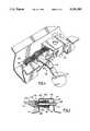
- FIG. 4is a perspective view, broken away, of part of the prior art brake mechanism of FIGS. 2 and 3;
- FIG. 5is a view along line 5--5 of FIG. 2.
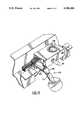
- FIG. 6is a perspective view of part of the brake mechanism forming the subject invention.
- FIG. 7is a bottom view, broken away, of the brake mechanism constructed in accordance with the present invention.
- FIG. 8is top view of a rear lammal forming part of the present invention.
- FIG. 9is a sectional view along line 9--9 of FIG. 8;
- FIG. 10is a side elevation of an alternative embodiment of a rear lammal
- FIG. 11is a bottom view of a chair seat tilt mechanism constructed in accordance with the present invention.
- FIG. 12is a sectional view along the line 12--12 of FIG. 11;
- FIG. 13is a perspective view, broken away, of part of the seat tilt mechanism forming the present invention.
- FIG. 1there is shown a chair 20 of the type generally found in an office environment.
- Chair 20includes supporting legs 22 each having a castor 24 attached at a lower end thereof. Legs 22 extend radially from a spindle support 26 which supports a spindle 28 which in turn is attached to a chair seat 30.
- a seat cushionis attachable to the top surface of seat 30.
- Chair 20is provided with a seat back 32 attached to one end of a seat back support arm 34. The other end of support arm 34 is attached to a seat back support mechanism indicated generally by numeral 36.
- a seat tilt mechanism indicated by numeral 40is secured to the bottom surface of seat 30.
- Seat tilt mechanism 40comprises a housing 42 having side walls 44.
- Seat back support mechanism 36includes a bracket 46 having side walls 48, an end wall 50 and a cam 52 mounted between side walls 48 and spaced from end wall 50 of the bracket thereby defining a passageway 54.
- Cam 52includes a cam handle 56 located on the outside of bracket 46.
- One end of seat back support arm 34(FIG. 1) is received in passageway 54 and rotation of handle 56 in one direction compresses and locks arm 34 in place thereby fixing seat back 32 at the desired height.
- Support arm 36is pivotally attached to seat tilt mechanism 40 by a rod 58 extending between side walls 44 of housing 42 and side walls 48 of bracket 46.
- a pair of spaced springs 60are mounted on rod 58 and are each provided with arms 62 and 64 with arm 62 urging against housing 42 and arm 64 urging against bracket 46, best seen in FIG. 3.
- the action of a user sitting in the chair leaning back against seat back 32causes bracket 46 to pivot about rod 58 against springs 60 so that when the user leans forward the springs return seat back 32 to the upright position.
- Seat tilt mechanism 40includes a brake mechanism 70 to lock seat 30 and seat back support mechanism 36 in place.
- Brake mechanism 70includes a spindle bracket 72 mounted in housing 42 into which seat spindle 28 is receivable.
- Spindle bracket 72comprises a rectangular frame 74 and a plurality of longitudinal, flat steel arms or front lammals 76 welded to frame 74. Each arm 76 is provided with a slot 78 through the end thereof spaced from frame 74. Both frame 74 and arms 76 are fabricated of heavy gauge steel.
- Spindle bracket 72is mounted in housing 42 by a pivot rod 80 extending between side walls 44 of the housing through frame 74.
- Brake mechanism 70includes a plurality of separate, longitudinal and flat steel rear lammals or arms 90 having holes 92 in one end thereof and slots 94 in the other end. Arms 90 are mounted on a rod 96 extending between side walls 48 of bracket 46 and transversely through arms 90 in holes 92. The other end of arms 90 are interleaved between the ends of arms 76 of spindle bracket 70 and a locking bolt 98 extends transversely through arms 76 and 90 through slots 78 and 94. Both sets of steel arms have a surface coating applied thereto for protection.
- Locking mechanism 100comprises locking bolt 98, which is threaded, extending between and through side walls 44 in holes 45 of housing 42. As discussed above, bolt 98 passes transversely through slots 78 and 94 in arms 76 and 90 respectively.
- Bolt 98includes a head portion 102 located on the outside of housing 42 and on the inside of a sheath 104 which protrudes through one of the side walls 44. Sheath 104 is rigidly affixed to side wall 44 and does not move.
- a spring 106is disposed within sheath 104 between side wall 44 and inturned end portion 108 of the sheath adjacent arms 90 and 76.
- threaded bolt 98passes through a sheath 110 and a nut 112 threadably received on the end of the bolt retains the sheath on the bolt, best seen in FIG. 5.
- Sheath 110abuts the outermost lammal arm and moves with bolt 98 so that in the locked position arms 76 and 90 are compressed between sheath 110 and the inturned portion 108 of sheath 104.
- Sheath 110 and bolt 98are slidable through hole 45.
- a locking arm or lever 114is secured to a frusto-conically shaped connector 115 which in turn is pivotally attached to sheath 104 by pin 116.
- Connector 115comprises two adjacent surfaces 117 and 118 disposed at an angle with respect to each other.
- Pivoting locking arm 114 until surface 117 is adjacent to the top surface of head 102acts to push bolt 98 inwards against the force of spring 106 thereby relieving the compression on arms 90 and 76.
- bolt 98is retracted by spring 106 thereby compressing arms 76 and 90 thereby locking mounting 46 and seat 30 in position.
- FIGS. 6 and 7illustrate a generally rectangular spindle bracket 120 having opposing side walls 122, opposing end walls 124 and a top surface 126.
- a hole 128extends through top surface 126 and is bordered by a collar 130 integrally formed with bracket 120.
- a metal sleeve 132is located in hole 128 and suitably sized so that it is tightly held in place against collar 130 in bracket 120.
- Spindle 28(FIG. 1) is received within hole 128 when the chair is assembled and the presence of metal sleeve 132 ensures a metal on metal coupling with the spindle and bracket 120.
- Spindle bracket 120includes various reinforcing webs 134 provided to increase the strength of the bracket. Bracket 120 is provided with holes 136 and 138 extending through opposed side walls 122. Holes 136 are for receiving a pivot rod for mounting bracket 120 in the tilt mechanism housing, as will be presently discussed. Bracket 120 includes a plurality of front lammals or arms 140 integrally formed therewith and extending from the end wall 124 of the bracket spaced furthest from hole 128. Arms 140 extend parallel to each other and are provided with elongate slots 142. Spindle bracket 120 is of one piece unitary construction and is moulded of a hard plastic material such as glass reinforced nylon.
- bracket 120This material has been found to produce a strong spindle bracket sufficient to withstand the stresses on arms 140 forming part of the bracket. Normal nylon would not be strong enough to withstand the stresses routinely applied to the bracket and therefore would not result in a safe bracket. In choosing alternate materials from which to construct bracket 120, due consideration must be given to this safety feature.
- a bushing(not shown) is positioned in hole 136 to receive the pivot rod so that the rod is not worn down by the bracket during use.
- the latterprovides a construction with less stress placed on the connection between arms 140 and the main body portion of the bracket compared to the prior art bracket 74 shown in FIG. 4. This is because bracket 120 is moulded with shorter arms 140 compared to arms 76 of bracket 74.
- Rear lammal 160is of one piece unitary construction being fabricated of a hard moulded plastic and includes a central body portion 162 provided with a plurality of parallel arms 164 extending from one end and a plurality of parallel arms 166 extending from the other end thereof.
- arms 166are provided with a hole 170 extending therethrough and arms 168 are each provided with a slot 172 extending therethrough. Holes 170 and slots 172 are in registration in each of the adjacent arms so that rods can be received through the holes and slots.
- Lammal 160is preferably fabricated of a hard material such as glass reinforced nylon. The inventors have found that normal nylon warps during extended usage due to the high stresses present on the lammal. Using shorter lammals may alleviate this problem.
- FIG. 10illustrates an alternative embodiment of a rear lammal shown at 180 which may be used in conjunction with spindle bracket 120 illustrated in FIG. 6.
- Lammal 180comprises a single elongate arm 182 having a hole 184 adjacent one end and a slot adjacent another end thereof.
- Lammals 180are essentially the same as those used in the prior art seat tilt mechanism of FIGS. 2 to 4.
- Lammal 180may be fabricated of steel or other hard materials such as glass filled nylon.
- a plurality of lammals 180would be used with spindle bracket 120. It will be appreciated by those skilled in the art that based on the foregoing discussion, lammal 160 is the preferred lammal to be used with spindle bracket 120.
- An assembled seat tilt mechanism 200 shown in FIGS. 11 and 12comprises arms 166 of rear lammal 160 interleaved with front lammals 140 of spindle bracket 120.
- Bolt 98 of locking mechanism 100extends through slots 142 and 172 of lammals 140 and arms 166 of lammal 160 respectively.
- Lammal 160is pivotally mounted on rod 96 extending between side walls 48 of bracket 46 through holes 170 in arms 164.
- the functioning of locking mechanism 100 of FIGS. 11 and 13is identical to that shown in FIG. 5.
- Spindle bracket 120is preferably fabricated of glass reinforced nylon to withstand the high stresses routinely applied to the spindle bracket.
- Lammal 160may also be fabricated of glass reinforced nylon. It will be appreciated that instead of lammal 160 being used, a plurality of lammals 180 (FIG. 10) may be used. Lammals 180 may be fabricated of steel such as in the prior art or alternatively may be moulded from glass reinforced nylon. However, those skilled in the art will appreciate the advantages associated with using the unitary lammal 160. This unitary lammal avoids the requirement of having to align individual arms relative to one another during assembly of tilt mechanism 70.
- the seat tilt mechanism of the present inventionmay be modified slightly to prevent pivotal movement of spindle bracket 120. Referring to FIGS. 1 and 13, this may be achieved by inserting a rod (not shown) through hole 138 of bracket 120 and side walls 44 of housing 42. In this way seat 30 is prevented from pivoting and only seat back 32 can pivot. The unitary brake now acts to lock and unlock seat back 32 only.
- arms 166By choosing the dimensions of arms 166 to ensure they are oversized with respect to arms 140, see FIG. 12, maximum friction is achieved between the arms in the locked position thereby giving a better seat and back rest lock. It has also been found that good frictional engagement between arms 140 and 160 is achieved when glass reinforced nylon is used for bracket 120 and steel used for arms 160.
- spindle bracket 120is much lighter and more economical to fabricate than the prior art metal spindle bracket discussed earlier. Since arms 140 are integrally formed with the rest of the bracket 120, there are no problems similar to those encountered with the prior art associated with the alignment of arms 140 relative to one another or with the quality of the connection between the arms and the rest of the bracket. In addition, spindle bracket 120 the provides a construction with less stress placed on the connection between arms 140 and the main body portion of the bracket compared to the prior art bracket 74 shown in FIG. 4. This is because bracket 120 is moulded with shorter arms 140 compared to arms 76 of bracket 74.
- the moulded unitary rear lammal 160is advantageous because it is lighter than the individual metal arms and arms 164 and 166 are fixed with respect to one another so the lammal can be rapidly mounted within tilt mechanism 200. This results in considerable savings over the fabrication and assembly of the tilt mechanism.
- unitary lammal 160provides for a smoother ride during movement of the seat and seat back due to arms 164 and 166 being held fixed relative to one another.
Landscapes
- Health & Medical Sciences (AREA)
- Dentistry (AREA)
- General Health & Medical Sciences (AREA)
- Chairs For Special Purposes, Such As Reclining Chairs (AREA)
- Braking Arrangements (AREA)
Abstract
Description
Claims (25)
Priority Applications (4)
| Application Number | Priority Date | Filing Date | Title |
|---|---|---|---|
| US07/965,206US5356200A (en) | 1992-10-23 | 1992-10-23 | Unitary brake for a chair tilt mechanism |
| CA002089695ACA2089695C (en) | 1992-10-23 | 1993-02-17 | Unitary brake for a chair tilt mechanism |
| PCT/CA1993/000433WO1994009682A1 (en) | 1992-10-23 | 1993-10-22 | Unitary brake for a chair tilt mechanism |
| AU52823/93AAU5282393A (en) | 1992-10-23 | 1993-10-22 | Unitary brake for a chair tilt mechanism |
Applications Claiming Priority (1)
| Application Number | Priority Date | Filing Date | Title |
|---|---|---|---|
| US07/965,206US5356200A (en) | 1992-10-23 | 1992-10-23 | Unitary brake for a chair tilt mechanism |
Publications (1)
| Publication Number | Publication Date |
|---|---|
| US5356200Atrue US5356200A (en) | 1994-10-18 |
Family
ID=25509633
Family Applications (1)
| Application Number | Title | Priority Date | Filing Date |
|---|---|---|---|
| US07/965,206Expired - Fee RelatedUS5356200A (en) | 1992-10-23 | 1992-10-23 | Unitary brake for a chair tilt mechanism |
Country Status (4)
| Country | Link |
|---|---|
| US (1) | US5356200A (en) |
| AU (1) | AU5282393A (en) |
| CA (1) | CA2089695C (en) |
| WO (1) | WO1994009682A1 (en) |
Cited By (21)
| Publication number | Priority date | Publication date | Assignee | Title |
|---|---|---|---|---|
| US5560682A (en)* | 1992-12-01 | 1996-10-01 | Klasse Pty Ltd | Adjustment mechanism for a chair |
| US5588706A (en)* | 1993-10-14 | 1996-12-31 | Sifa Sitzfabrik Gmbh | Control mechanism for the seat carriers of chairs, especially swivel chairs |
| US5664834A (en)* | 1996-10-08 | 1997-09-09 | Hsu; Hsiu-Lan | Adjusting device of a chair |
| US5676425A (en)* | 1996-03-19 | 1997-10-14 | R.A.M. Machines (1990) Ltd. | Releasable lock forchair control mechanism |
| US5685607A (en)* | 1994-10-17 | 1997-11-11 | S I F A Sitzfabrik Gmbh | Office chair seat carrier |
| US5863099A (en)* | 1995-02-15 | 1999-01-26 | Ashfield Engineering Company Wexford Limited | Actuator for a chair mechanism lock |
| WO1999056839A2 (en) | 1998-05-07 | 1999-11-11 | Reynolds Dwight H | Dual-locking automatic positioning interface for a snowboard boot binding |
| WO2001004508A1 (en)* | 1999-07-08 | 2001-01-18 | Lord Corporation | Damper including resilient friction member and seat assembly using same |
| US6322144B1 (en)* | 1997-08-19 | 2001-11-27 | Sifa Sitzfabrik Gmbh | Seat support for revolving chairs |
| US6467845B1 (en)* | 2001-09-21 | 2002-10-22 | Su-Ming Chen | Chair with a locking unit |
| US6467842B1 (en)* | 2001-04-09 | 2002-10-22 | Aur Hann Co., Ltd. | Locating structure of a reclining leisure chair |
| US6598936B1 (en) | 2001-04-11 | 2003-07-29 | Michael N. Klein | Multi-task mid-pivot chair control mechanism |
| WO2005027690A1 (en)* | 2003-09-25 | 2005-03-31 | Armet S.P.A. | Friction-plate adjusting device and method for the manufacture thereof |
| US20050093345A1 (en)* | 2003-10-29 | 2005-05-05 | Leggett & Platt, Ltd. | Switching apparatus |
| US7017992B2 (en) | 2003-02-18 | 2006-03-28 | Warvel Products, Inc.-N.C. | Chair control device for a tiltable chair |
| USD528328S1 (en)* | 2004-04-08 | 2006-09-19 | Ergo-Industrial Seating Systems Ltd. | Shaped levers |
| US7614697B1 (en)* | 2008-06-06 | 2009-11-10 | Fon Chin Industrial Co., Ltd. | Coupling mechanism interposed between a seat and a back of a chair to prevent a reclining motion of the back from tilting the seat |
| USD626061S1 (en)* | 2009-10-30 | 2010-10-26 | Thule Sweden Ab | Underside of a cargo box lid |
| US20110304182A1 (en)* | 2010-06-09 | 2011-12-15 | Therrien Yves | Chair adjustment mechanism |
| USD904099S1 (en)* | 2018-06-22 | 2020-12-08 | P.S. Pibbs, Inc. | Reclining mechanism for a threading chair |
| US20240280168A1 (en)* | 2023-02-22 | 2024-08-22 | Hsin-Hua Chen | Control pull-bar structure of chair adjusting device |
Families Citing this family (3)
| Publication number | Priority date | Publication date | Assignee | Title |
|---|---|---|---|---|
| BE1008843A3 (en)* | 1994-10-13 | 1996-08-06 | Cauwer Kris De | Multi-purpose folding item of furniture |
| IT1296230B1 (en)* | 1997-09-22 | 1999-06-18 | Aaa Ne Italy Made S R L | SWINGING SUPPORT FOR THE BACK OF A SEAT |
| DE29812598U1 (en) | 1998-07-15 | 1998-10-22 | SIFA Sitzfabrik GmbH, 92237 Sulzbach-Rosenberg | Clamp for seat supports of chairs |
Citations (23)
| Publication number | Priority date | Publication date | Assignee | Title |
|---|---|---|---|---|
| FR737228A (en)* | 1931-11-10 | 1932-12-08 | Tan Sad Chair Co 1931 Ltd | Adjustable backrest or support for seats |
| US2278080A (en)* | 1939-04-04 | 1942-03-31 | Koenigkramer Frank | Tilting structure for chairs and the like |
| US3093413A (en)* | 1962-02-21 | 1963-06-11 | Jr Charles W Chancellor | Chair with double pivot spring assembly |
| GB1256388A (en)* | 1969-09-23 | 1971-12-08 | Doerner Products Co Ltd | Improvements in or relating to chairs |
| FR2101996A6 (en)* | 1967-10-11 | 1972-03-31 | Stoll Kg Christof | |
| US3740791A (en)* | 1972-04-24 | 1973-06-26 | Case Co J I | Control arm assembly for hinged members |
| GB1400509A (en)* | 1972-04-19 | 1975-07-16 | Drabert F | Seats |
| GB1430576A (en)* | 1972-05-18 | 1976-03-31 | Evertaut Ltd | Adjustable back rests of chairs |
| US4198094A (en)* | 1977-08-25 | 1980-04-15 | Anders Bjerknes | Working chair |
| US4314728A (en)* | 1980-05-01 | 1982-02-09 | Steelcase Inc. | Chair control |
| FR2491310A1 (en)* | 1980-10-03 | 1982-04-09 | Cannone Vincent | Back rest adjustment for seat - controls height and position and consists of rotary element in two parts receiving sliding arm which supports backrest |
| US4392686A (en)* | 1979-07-06 | 1983-07-12 | Steifensand Sitzmobel- Und Tischfabrik, Inh. | Adjustable office chair |
| DE3424756A1 (en)* | 1983-08-12 | 1985-02-28 | Konrad 8501 Burgthann Neumüller | SEAT CARRIER FOR CHAIRS, IN PARTICULAR WORK SWIVEL CHAIRS |
| US4596421A (en)* | 1983-01-21 | 1986-06-24 | Pierre Schmitz | Office chair |
| US4629249A (en)* | 1984-01-18 | 1986-12-16 | Okamura Corporation | Device for a reclining chair |
| US4693514A (en)* | 1984-07-10 | 1987-09-15 | Voelkle Rolf | Chair having a clamping device for adjusting the inclination of the back and/or seat |
| US4718725A (en)* | 1985-08-02 | 1988-01-12 | Firma August Froscher G.M.B.H. & Co. K.G. | Support-and adjusting device for seat and backrest on a work chair |
| US4889385A (en)* | 1988-03-09 | 1989-12-26 | American Seating Company | Chair seat-and-back support |
| US4936630A (en)* | 1988-04-07 | 1990-06-26 | Northeastern Components (International) Ltd. | Chair adjuster |
| US4966412A (en)* | 1984-10-24 | 1990-10-30 | Burositzmobelfabrik Friedrich-W. Dauphin Gmbh & Co. | Chair, in particular office chair |
| EP0394784A1 (en)* | 1989-04-27 | 1990-10-31 | Lineager S.R.L. | Friction device for adjusting the inclination of a seat, in particular an office chair |
| US5066069A (en)* | 1990-05-03 | 1991-11-19 | Systems Furniture Company | Chair back and seat adjustment mechanism |
| EP0549538A1 (en)* | 1991-12-20 | 1993-06-30 | CO.FE.MO. S.p.A. | Central stand for supporting and adjusting the inclination of chairs with oscillating seat |
- 1992
- 1992-10-23USUS07/965,206patent/US5356200A/ennot_activeExpired - Fee Related
- 1993
- 1993-02-17CACA002089695Apatent/CA2089695C/ennot_activeExpired - Fee Related
- 1993-10-22AUAU52823/93Apatent/AU5282393A/ennot_activeAbandoned
- 1993-10-22WOPCT/CA1993/000433patent/WO1994009682A1/enactiveApplication Filing
Patent Citations (25)
| Publication number | Priority date | Publication date | Assignee | Title |
|---|---|---|---|---|
| FR737228A (en)* | 1931-11-10 | 1932-12-08 | Tan Sad Chair Co 1931 Ltd | Adjustable backrest or support for seats |
| US2278080A (en)* | 1939-04-04 | 1942-03-31 | Koenigkramer Frank | Tilting structure for chairs and the like |
| US3093413A (en)* | 1962-02-21 | 1963-06-11 | Jr Charles W Chancellor | Chair with double pivot spring assembly |
| FR2101996A6 (en)* | 1967-10-11 | 1972-03-31 | Stoll Kg Christof | |
| GB1256388A (en)* | 1969-09-23 | 1971-12-08 | Doerner Products Co Ltd | Improvements in or relating to chairs |
| GB1400509A (en)* | 1972-04-19 | 1975-07-16 | Drabert F | Seats |
| US3740791A (en)* | 1972-04-24 | 1973-06-26 | Case Co J I | Control arm assembly for hinged members |
| GB1430576A (en)* | 1972-05-18 | 1976-03-31 | Evertaut Ltd | Adjustable back rests of chairs |
| US4198094B1 (en)* | 1977-08-25 | 1991-04-02 | Working chair | |
| US4198094A (en)* | 1977-08-25 | 1980-04-15 | Anders Bjerknes | Working chair |
| US4392686A (en)* | 1979-07-06 | 1983-07-12 | Steifensand Sitzmobel- Und Tischfabrik, Inh. | Adjustable office chair |
| US4314728A (en)* | 1980-05-01 | 1982-02-09 | Steelcase Inc. | Chair control |
| FR2491310A1 (en)* | 1980-10-03 | 1982-04-09 | Cannone Vincent | Back rest adjustment for seat - controls height and position and consists of rotary element in two parts receiving sliding arm which supports backrest |
| US4596421A (en)* | 1983-01-21 | 1986-06-24 | Pierre Schmitz | Office chair |
| DE3424756A1 (en)* | 1983-08-12 | 1985-02-28 | Konrad 8501 Burgthann Neumüller | SEAT CARRIER FOR CHAIRS, IN PARTICULAR WORK SWIVEL CHAIRS |
| US4636004A (en)* | 1983-08-12 | 1987-01-13 | Neumueller Konrad | Seat mounting for chairs, in particular swivel-type desk chairs |
| US4629249A (en)* | 1984-01-18 | 1986-12-16 | Okamura Corporation | Device for a reclining chair |
| US4693514A (en)* | 1984-07-10 | 1987-09-15 | Voelkle Rolf | Chair having a clamping device for adjusting the inclination of the back and/or seat |
| US4966412A (en)* | 1984-10-24 | 1990-10-30 | Burositzmobelfabrik Friedrich-W. Dauphin Gmbh & Co. | Chair, in particular office chair |
| US4718725A (en)* | 1985-08-02 | 1988-01-12 | Firma August Froscher G.M.B.H. & Co. K.G. | Support-and adjusting device for seat and backrest on a work chair |
| US4889385A (en)* | 1988-03-09 | 1989-12-26 | American Seating Company | Chair seat-and-back support |
| US4936630A (en)* | 1988-04-07 | 1990-06-26 | Northeastern Components (International) Ltd. | Chair adjuster |
| EP0394784A1 (en)* | 1989-04-27 | 1990-10-31 | Lineager S.R.L. | Friction device for adjusting the inclination of a seat, in particular an office chair |
| US5066069A (en)* | 1990-05-03 | 1991-11-19 | Systems Furniture Company | Chair back and seat adjustment mechanism |
| EP0549538A1 (en)* | 1991-12-20 | 1993-06-30 | CO.FE.MO. S.p.A. | Central stand for supporting and adjusting the inclination of chairs with oscillating seat |
Cited By (27)
| Publication number | Priority date | Publication date | Assignee | Title |
|---|---|---|---|---|
| US5560682A (en)* | 1992-12-01 | 1996-10-01 | Klasse Pty Ltd | Adjustment mechanism for a chair |
| US5588706A (en)* | 1993-10-14 | 1996-12-31 | Sifa Sitzfabrik Gmbh | Control mechanism for the seat carriers of chairs, especially swivel chairs |
| US5685607A (en)* | 1994-10-17 | 1997-11-11 | S I F A Sitzfabrik Gmbh | Office chair seat carrier |
| US5863099A (en)* | 1995-02-15 | 1999-01-26 | Ashfield Engineering Company Wexford Limited | Actuator for a chair mechanism lock |
| US5676425A (en)* | 1996-03-19 | 1997-10-14 | R.A.M. Machines (1990) Ltd. | Releasable lock forchair control mechanism |
| US5664834A (en)* | 1996-10-08 | 1997-09-09 | Hsu; Hsiu-Lan | Adjusting device of a chair |
| US6322144B1 (en)* | 1997-08-19 | 2001-11-27 | Sifa Sitzfabrik Gmbh | Seat support for revolving chairs |
| WO1999056839A2 (en) | 1998-05-07 | 1999-11-11 | Reynolds Dwight H | Dual-locking automatic positioning interface for a snowboard boot binding |
| WO2001004508A1 (en)* | 1999-07-08 | 2001-01-18 | Lord Corporation | Damper including resilient friction member and seat assembly using same |
| US6386528B1 (en) | 1999-07-08 | 2002-05-14 | Lord Corporation | Damper including resilient friction member and seat assembly using same |
| US6669298B2 (en) | 1999-07-08 | 2003-12-30 | Lord Corporation | Seat assembly including resilent friction member |
| US6467842B1 (en)* | 2001-04-09 | 2002-10-22 | Aur Hann Co., Ltd. | Locating structure of a reclining leisure chair |
| US6598936B1 (en) | 2001-04-11 | 2003-07-29 | Michael N. Klein | Multi-task mid-pivot chair control mechanism |
| US6779847B2 (en) | 2001-04-11 | 2004-08-24 | L & P Property Management Company | Multi-task mid-pivot chair control mechanism |
| US6467845B1 (en)* | 2001-09-21 | 2002-10-22 | Su-Ming Chen | Chair with a locking unit |
| US7017992B2 (en) | 2003-02-18 | 2006-03-28 | Warvel Products, Inc.-N.C. | Chair control device for a tiltable chair |
| WO2005027690A1 (en)* | 2003-09-25 | 2005-03-31 | Armet S.P.A. | Friction-plate adjusting device and method for the manufacture thereof |
| US7380884B2 (en) | 2003-10-29 | 2008-06-03 | Leggett & Platt Ltd. | Switching apparatus |
| US20050093345A1 (en)* | 2003-10-29 | 2005-05-05 | Leggett & Platt, Ltd. | Switching apparatus |
| USD528328S1 (en)* | 2004-04-08 | 2006-09-19 | Ergo-Industrial Seating Systems Ltd. | Shaped levers |
| US7614697B1 (en)* | 2008-06-06 | 2009-11-10 | Fon Chin Industrial Co., Ltd. | Coupling mechanism interposed between a seat and a back of a chair to prevent a reclining motion of the back from tilting the seat |
| USD626061S1 (en)* | 2009-10-30 | 2010-10-26 | Thule Sweden Ab | Underside of a cargo box lid |
| US20110304182A1 (en)* | 2010-06-09 | 2011-12-15 | Therrien Yves | Chair adjustment mechanism |
| US8454091B2 (en)* | 2010-06-09 | 2013-06-04 | Groupe Dutailier Inc. | Chair adjustment mechanism |
| USD904099S1 (en)* | 2018-06-22 | 2020-12-08 | P.S. Pibbs, Inc. | Reclining mechanism for a threading chair |
| US20240280168A1 (en)* | 2023-02-22 | 2024-08-22 | Hsin-Hua Chen | Control pull-bar structure of chair adjusting device |
| US12203538B2 (en)* | 2023-02-22 | 2025-01-21 | Hsin-Hua Chen | Control pull-bar structure of chair adjusting device |
Also Published As
| Publication number | Publication date |
|---|---|
| WO1994009682A1 (en) | 1994-05-11 |
| AU5282393A (en) | 1994-05-24 |
| CA2089695C (en) | 1995-08-15 |
| CA2089695A1 (en) | 1994-04-24 |
Similar Documents
| Publication | Publication Date | Title |
|---|---|---|
| US5356200A (en) | Unitary brake for a chair tilt mechanism | |
| CA1098021A (en) | Office chair | |
| US6149236A (en) | Chair frame, control mechanism and upholstery | |
| US5447357A (en) | Chair with inclinable seat | |
| US5244253A (en) | Height adjustment control for a chair | |
| US5397165A (en) | Synchronous movement adjustable seat support | |
| US5658045A (en) | Chair with adjustable seat and backrest | |
| US6439661B1 (en) | Chair mechanism | |
| US6557939B1 (en) | Adjustment mechanism, back cover and arm rest for a chair | |
| US20020113475A1 (en) | Method for adjusting a seat | |
| US5904401A (en) | Recliner chair | |
| CA2284406A1 (en) | Seat plate for a seat of adjustable seat depth | |
| JPH0243481B2 (en) | ||
| US6276755B1 (en) | Swivel arrangement for a chair seat | |
| US6092870A (en) | Rocking and gliding mechanism for furniture | |
| US4607883A (en) | Reclining mechanism for easy chair | |
| KR20190079955A (en) | The slide structure of the seat for the chair | |
| JP2003079472A (en) | Rocking chair and its base | |
| EP1467642B1 (en) | Mobile joint with several stable positions, suitable for use in furniture | |
| JP2020058758A (en) | Chair and manufacturing method of the same | |
| US20100141002A1 (en) | Biasing mechanism | |
| US3709535A (en) | Hinge iron for posture chair | |
| CN219537857U (en) | Chair seat capable of being synchronously movably adjusted | |
| US20020145322A1 (en) | Locating structure of a reclining leisure chair | |
| CA1056291A (en) | Chair structure and tilt mechanism therefor |
Legal Events
| Date | Code | Title | Description |
|---|---|---|---|
| AS | Assignment | Owner name:FAULTLESS-DOERNER MANUFACTURING INC. Free format text:ASSIGNMENT OF ASSIGNORS INTEREST.;ASSIGNORS:STUMPF, WILLIAM S.;PATTON, ART A.;REEL/FRAME:006292/0400 Effective date:19921023 | |
| FEPP | Fee payment procedure | Free format text:PAYOR NUMBER ASSIGNED (ORIGINAL EVENT CODE: ASPN); ENTITY STATUS OF PATENT OWNER: LARGE ENTITY | |
| AS | Assignment | Owner name:BABCOCK INDUSTRIES CANADA IN., CANADA Free format text:CHANGE OF NAME;ASSIGNOR:FAULTLESS-DOERNER MANUFACTURING INC.;REEL/FRAME:006414/0381 Effective date:19930101 Owner name:1012697 ONTARIO LIMITED, CANADA Free format text:ASSIGNMENT OF ASSIGNORS INTEREST.;ASSIGNOR:BABCOCK INDUSTRIES CANADA INC.;REEL/FRAME:006414/0376 Effective date:19930114 | |
| FEPP | Fee payment procedure | Free format text:PAYER NUMBER DE-ASSIGNED (ORIGINAL EVENT CODE: RMPN); ENTITY STATUS OF PATENT OWNER: LARGE ENTITY Free format text:PAYOR NUMBER ASSIGNED (ORIGINAL EVENT CODE: ASPN); ENTITY STATUS OF PATENT OWNER: LARGE ENTITY | |
| AS | Assignment | Owner name:DOERNER PRODUCTS LTD., ONTARIO Free format text:CHANGE OF NAME;ASSIGNOR:1012697 ONTARIO LIMITED;REEL/FRAME:006920/0853 Effective date:19930428 | |
| FPAY | Fee payment | Year of fee payment:4 | |
| AS | Assignment | Owner name:LEGGETT & PLATT LTD., CANADA Free format text:MERGER;ASSIGNOR:NORTHFIELD METAL PROCUCTS (1994) LTD.;REEL/FRAME:012721/0376 Effective date:19981222 Owner name:NORTHFIELD METAL PRODUCTS (1994) LTD., CANADA Free format text:CHANGE OF NAME;ASSIGNOR:DOERNER PRODUCTS LTD.;REEL/FRAME:012721/0490 Effective date:19940318 | |
| REMI | Maintenance fee reminder mailed | ||
| LAPS | Lapse for failure to pay maintenance fees | ||
| STCH | Information on status: patent discontinuation | Free format text:PATENT EXPIRED DUE TO NONPAYMENT OF MAINTENANCE FEES UNDER 37 CFR 1.362 | |
| FP | Lapsed due to failure to pay maintenance fee | Effective date:20021018 | |
| AS | Assignment | Owner name:LEGGETT & PLATT CANADA CO., CANADA Free format text:CERTIFICATE OF AMALGAMATION;ASSIGNOR:LEGGETT & PLATT LTD.;REEL/FRAME:017045/0208 Effective date:20041101 |