US5355608A - Concealed laser module sight apparatus - Google Patents
Concealed laser module sight apparatusDownload PDFInfo
- Publication number
- US5355608A US5355608AUS08/073,766US7376693AUS5355608AUS 5355608 AUS5355608 AUS 5355608AUS 7376693 AUS7376693 AUS 7376693AUS 5355608 AUS5355608 AUS 5355608A
- Authority
- US
- United States
- Prior art keywords
- chassis
- handgun
- light source
- front face
- sight
- Prior art date
- Legal status (The legal status is an assumption and is not a legal conclusion. Google has not performed a legal analysis and makes no representation as to the accuracy of the status listed.)
- Expired - Fee Related
Links
- 239000012528membraneSubstances0.000claimsabstractdescription25
- 230000004297night visionEffects0.000claimsdescription3
- 238000010304firingMethods0.000claimsdescription2
- 238000000034methodMethods0.000description14
- 239000000463materialSubstances0.000description6
- 229910000831SteelInorganic materials0.000description4
- 239000012212insulatorSubstances0.000description4
- 230000004048modificationEffects0.000description4
- 238000012986modificationMethods0.000description4
- 239000010959steelSubstances0.000description4
- 239000004593EpoxySubstances0.000description3
- 238000009413insulationMethods0.000description3
- 230000035939shockEffects0.000description3
- 230000008901benefitEffects0.000description2
- 230000015556catabolic processEffects0.000description2
- 230000000694effectsEffects0.000description2
- 230000008569processEffects0.000description2
- 230000001012protectorEffects0.000description2
- 229910001369BrassInorganic materials0.000description1
- ATJFFYVFTNAWJD-UHFFFAOYSA-NTinChemical group[Sn]ATJFFYVFTNAWJD-UHFFFAOYSA-N0.000description1
- 238000005299abrasionMethods0.000description1
- 239000006096absorbing agentSubstances0.000description1
- 238000004026adhesive bondingMethods0.000description1
- 230000002411adverseEffects0.000description1
- 229910052782aluminiumInorganic materials0.000description1
- XAGFODPZIPBFFR-UHFFFAOYSA-NaluminiumChemical compound[Al]XAGFODPZIPBFFR-UHFFFAOYSA-N0.000description1
- 210000000988bone and boneAnatomy0.000description1
- 239000010951brassSubstances0.000description1
- 230000008859changeEffects0.000description1
- 230000007797corrosionEffects0.000description1
- 238000005260corrosionMethods0.000description1
- 238000005336crackingMethods0.000description1
- 230000000881depressing effectEffects0.000description1
- 230000007613environmental effectEffects0.000description1
- 239000011521glassSubstances0.000description1
- 238000009434installationMethods0.000description1
- 238000004519manufacturing processMethods0.000description1
- 229910052751metalInorganic materials0.000description1
- 239000002184metalSubstances0.000description1
- 230000003387muscularEffects0.000description1
- 239000012811non-conductive materialSubstances0.000description1
- 229920000642polymerPolymers0.000description1
- 230000029058respiratory gaseous exchangeEffects0.000description1
- 238000005476solderingMethods0.000description1
- 238000001228spectrumMethods0.000description1
- 229910001220stainless steelInorganic materials0.000description1
- 239000010935stainless steelSubstances0.000description1
- 230000004083survival effectEffects0.000description1
- XLYOFNOQVPJJNP-UHFFFAOYSA-NwaterSubstancesOXLYOFNOQVPJJNP-UHFFFAOYSA-N0.000description1
Images


Classifications
- F—MECHANICAL ENGINEERING; LIGHTING; HEATING; WEAPONS; BLASTING
- F42—AMMUNITION; BLASTING
- F42B—EXPLOSIVE CHARGES, e.g. FOR BLASTING, FIREWORKS, AMMUNITION
- F42B3/00—Blasting cartridges, i.e. case and explosive
- F42B3/10—Initiators therefor
- F42B3/113—Initiators therefor activated by optical means, e.g. laser, flashlight
- F—MECHANICAL ENGINEERING; LIGHTING; HEATING; WEAPONS; BLASTING
- F41—WEAPONS
- F41A—FUNCTIONAL FEATURES OR DETAILS COMMON TO BOTH SMALLARMS AND ORDNANCE, e.g. CANNONS; MOUNTINGS FOR SMALLARMS OR ORDNANCE
- F41A19/00—Firing or trigger mechanisms; Cocking mechanisms
- F41A19/01—Counting means indicating the number of shots fired
- F—MECHANICAL ENGINEERING; LIGHTING; HEATING; WEAPONS; BLASTING
- F41—WEAPONS
- F41A—FUNCTIONAL FEATURES OR DETAILS COMMON TO BOTH SMALLARMS AND ORDNANCE, e.g. CANNONS; MOUNTINGS FOR SMALLARMS OR ORDNANCE
- F41A19/00—Firing or trigger mechanisms; Cocking mechanisms
- F41A19/58—Electric firing mechanisms
- F—MECHANICAL ENGINEERING; LIGHTING; HEATING; WEAPONS; BLASTING
- F41—WEAPONS
- F41A—FUNCTIONAL FEATURES OR DETAILS COMMON TO BOTH SMALLARMS AND ORDNANCE, e.g. CANNONS; MOUNTINGS FOR SMALLARMS OR ORDNANCE
- F41A21/00—Barrels; Gun tubes; Muzzle attachments; Barrel mounting means
- F41A21/30—Silencers
- F—MECHANICAL ENGINEERING; LIGHTING; HEATING; WEAPONS; BLASTING
- F41—WEAPONS
- F41A—FUNCTIONAL FEATURES OR DETAILS COMMON TO BOTH SMALLARMS AND ORDNANCE, e.g. CANNONS; MOUNTINGS FOR SMALLARMS OR ORDNANCE
- F41A9/00—Feeding or loading of ammunition; Magazines; Guiding means for the extracting of cartridges
- F41A9/61—Magazines
- F41A9/62—Magazines having means for indicating the number of cartridges left in the magazine, e.g. last-round indicators
- F—MECHANICAL ENGINEERING; LIGHTING; HEATING; WEAPONS; BLASTING
- F41—WEAPONS
- F41G—WEAPON SIGHTS; AIMING
- F41G1/00—Sighting devices
- F41G1/32—Night sights, e.g. luminescent
- F41G1/34—Night sights, e.g. luminescent combined with light source, e.g. spot light
- F41G1/35—Night sights, e.g. luminescent combined with light source, e.g. spot light for illuminating the target, e.g. flash lights
- F—MECHANICAL ENGINEERING; LIGHTING; HEATING; WEAPONS; BLASTING
- F41—WEAPONS
- F41G—WEAPON SIGHTS; AIMING
- F41G1/00—Sighting devices
- F41G1/32—Night sights, e.g. luminescent
- F41G1/34—Night sights, e.g. luminescent combined with light source, e.g. spot light
- F41G1/36—Night sights, e.g. luminescent combined with light source, e.g. spot light with infrared light source
- F—MECHANICAL ENGINEERING; LIGHTING; HEATING; WEAPONS; BLASTING
- F42—AMMUNITION; BLASTING
- F42C—AMMUNITION FUZES; ARMING OR SAFETY MEANS THEREFOR
- F42C13/00—Proximity fuzes; Fuzes for remote detonation
- F42C13/02—Proximity fuzes; Fuzes for remote detonation operated by intensity of light or similar radiation
- F42C13/026—Remotely actuated projectile fuzes operated by optical transmission links
Definitions
- the inventionrelates to laser sights for use on small firearms, particularly semi-automatic handguns.
- Sight picture and aimare critical if the shooter is to fire the most accurate shot or series of shots.
- the top of the front sightshould be level with the top of the rear sight, with an equal amount of light on either side of the front sight.
- Using this sight picturerequires that the shooter focus his shooting eye so that the sights are in focus and the target is out of focus.
- the triggerall of the above must be maintained while the trigger is released using direct, even pressure to keep the barrel of the gun pointing at the target.
- a solution to this problemhas been the introduction of laser sights for use with handguns.
- the typical laser sightis mounted on the top on the handgun or on the bottom.
- the laser sightwhen properly aligned, places a red light dot on the target where the bullet will strike if the gun is fired.
- Using this type of sightenables the law officer to rapidly instinctively properly position the weapon and be certain of his/her intended target.
- Using a laser sightenables accurate shots to be fired at distances of more than 50 feet, sufficient for most combat law enforcement situations requiring the use of handguns.
- the use of the recoil spring guide to house the laser sight componentsenables the firearm to be holstered in a normal manner.
- the use of the spring recoil guidepresents alignment problems to ensure accuracy. In other words, the laser within the recoil guide is difficult to align with the barrel of the firearm. Therefore, misalignment of the sight resulting in poor accuracy is likely.
- prior art laser deviceshave several disadvantages. As they are mounted either on the top or the bottom of the weapon, the balance of the gun is disturbed which makes it more difficult for the shooter to rapidly use his/her instinctive sighting technique to move gun into alignment for hitting the desired target. Also, since prior art laser sights are very bulky in comparison to traditional mechanical sights, the weapon cannot be used in a standard holster. Further, the laser sight is extremely vulnerable to being hit due to extending substantially beyond the normal profile of the weapon and thereby misalignment of the sight and defeating the advantages offered by the laser sight. A laser sight capable of being installed in a semi-automatic handgun, easily and accurately adjustable, is not disclosed in the prior art.
- the inventionis a laser sight for an autoloading handgun, said handgun having a barrel and a spring recoil guide, a trigger, a frame, a slide having a cross-sectional profile with a front face having two holes therein, with one hole corresponding to the diameter of the barrel and the other hole corresponding to the diameter of the spring recoil guide.
- the inventionhas a chassis, having a cross-sectional profile corresponding to the cross-sectional profile of the slide of said handgun, said chassis having a front face, a back face, and having two holes extending therethrough from the back face to the front face of said chassis, with the holes corresponding to the holes in the front face of the slide of said handgun, with said chassis having at least one light source wherein the light of said light source is emitted from the front face of said chassis, and with the back face of said chassis securely mounted on the front face of the slide of said handgun.
- FIG. 1is a breakdown view of typical autoloading handgun, in this, the SIG Model P228.
- FIG. 2is a cross-sectional view of the laser diode sighting system attached to the autoloading handgun shown in FIG. 1 in accordance with the invention.
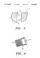
- FIG. 3is a detailed cross-sectional view of the sighting system chassis locked to the slide of the typical handgun.
- FIG. 4is a detailed isometric view of the chassis bushing.
- FIG. 5is a front isometric view of chassis.
- FIG. 6is a cross-sectional view of the batten pack.
- FIG. 7is a detailed view of the trigger switch.
- FIG. 8is a detailed flattened view of the membrane control switch.
- FIG. 9is rear view of the chassis showing the retainer member in place.
- FIG. 10is cross-sectional view of the laser module assembly within the chassis.
- FIG. 1is breakdown view of a typical autoloading handgun which can be adapted to incorporate a concealed laser module sight in accordance with the invention.
- the pistol shownis SIG-SAUER Model P228, 9 mm, with a 13 cartridge clip or magazine 101.
- This particular pistolhas been adopted by numerous military and law enforcement agencies as the weapon of choice because of its large magazine capacity, reliability, and accuracy.
- slide 4guided by recoil spring guide 2 and tensioned by recoil spring 46, is slid backwards along frame 45, tensioning recoil spring 46.
- Barrel 30 and recoil spring guide 2extend through barrel hole 103 and recoil spring guide hole 3 respectively.
- spring 46causes slide 4 to move forward, strip a round (not shown) from magazine 101, and place the cartridge into the firing chamber of barrel 30.
- slide 4is in its most forward position on frame 45, recoil spring guide 2 and barrel 30 are substantially flush with front face 104 of slide 4 via their respective holes 3 and 103.
- Some autoloading handgunssuch as the Colt Government Model 45 (not shown), incorporate a barrel bushing that positions barrel 30 within barrel hole 103 of slide 4.
- the barrel bushing in that modelextends slightly beyond the front face 104 of slide 4.
- Othersuch as the S & W Model 39, incorporate a barrel bushing that also acts as a bushing for recoil spring guide 2.
- the S & W bushingoccupies a substantial portion of the front face 104 of slide 4.
- the inventioncan be adapted to fit any autoloading handgun by merely making minor changes as will be shown later.
- Recoil spring guide 2is modified to house a concealed battery compartment to power a laser that is mounted in a chassis, adapted to be attached to the front face 104 of slide 4. Further, the chassis is provided with holes corresponding to barrel hole 103 and spring recoil guide hole 3 so that the normal functioning of the firearm does not have to altered. This enables the handgun to function in every respect the same as a firearm not equipped with laser sight if the sight is not turned on. Yet, when the laser sight is needed, the invention is easily activated by a conveniently placed switches will be discussed below.
- FIG. 2is a cross-sectional view of the laser diode sighting system 10 attached to the autoloading handgun shown in FIG. 1 in accordance with the invention.
- the laser diode sighting system 10has five subsystems, laser diode chassis 12, retaining bushing 36, membrane switch 18, recoil spring guide battery pack 14 and the trigger switch 16.
- the laser diode chassis 12is dimensioned to have the same profile as slide 4. Chassis 12 also has holes 103' and 3' that correspond to barrel hole 103 and spring recoil guide hole 3. Since the barrel 30 of the Sig Model P288 tilts upward when slide 4 is in the fully retracted position, hole 103' is modified accordingly. Also, hole 3' is dimensioned to allow recoil spring guide 2 to slide through when slide 4 travels backwards.
- Chassis 12is held in place on front face 104 by means of retaining bushing 36.
- chassis 12mounts on the front slide face 104 of the slide 4.
- Retaining bushing 36extends from the inside the spring housing 44 of the slide 4 out through the recoil spring guide hole 3 where as the threads 46 extended out, screw into the chassis threaded hole 48 in chassis 12.
- Bushing 36has an opening 51 that corresponds to diameter of battery pack 14 so that battery pack 14 may easily slide therethrough.
- Bushing 36holds the back surface 52 of chassis 12 snug against the front slide face 104 of the slide 4. As shown in the detail FIG. 3, locking radiuses 54 prohibit the laser diode chassis 12 from rotating by matching with radius 56 on front of slide 4. This is a preferred method. Other methods may be by gluing, pinning, notching, etc. depending on the configuration of the front face 104 of slide 4. For example, for handguns that use a barrel bushing, a second bushing may be used in addition to bushing 36 or in lieu of, to hold chassis 12 firmly in place.
- Laser diode chassis 12is preferably made of a heat treatable steel material. This would make a more durable housing to resist against damage. However, other materials for chassis 12 are also suitable such as hard plastic and aluminum.
- Lens protector 90will be glued in from the inside of the laser diode chassis 12.
- Lens protector 90is preferably made of material that is clear to allow a light beam to travel through it without distorting it and will resist flash burns, residue, abrasion and keep water and dirt from getting into the laser diode chassis 12. Clear glass would be a preferable material.
- retaining bushing 36is preferably made of a high tensile stainless steel that resists cracking. Slot 50 in retaining bushing 36 allows for ease of installation with a screwdriver.
- FIG. 5is a front isometric view of chassis 12 and membrane switch 18.
- Chassis 12houses one or more laser diode lights 58 with a collimating lens 60 (shown in FIG. 2).
- Laser diode light 58 with a collimating lens 60is preferably the type manufactured by Roam or Lyte Obtronics. It should be recognized that light 58 could also be a standard incandescent bulb to act as a flash light.
- the laser diode light 58 with a collimating 60can be positioned anywhere on the face 64 of the chassis. However, the preferable placement is as shown with one light opening 58 emitting a red beam and the other light opening 58 emitting an infrared beam to be detected by night vision goggles.
- Socket head set screws 110are preferably 2-56 UNEF socket head set screw modified with chamfer. This allows wedging along surface light 58 thereby aligning laser diode light 58 with collimating lens 60 in relation with barrel 30.
- the preferred method of mounting the chassis to the slidelimits the amount of stack-up tolerances in relation to the laser diode and the center line of the barrel, whereas, prior art devices mount the diode in other locations, such below the slide or in the recoil guide, which may substantially effect the accuracy of the sighting apparatus.
- the shootercan reflect his/her personal shooting habits such as pulling the pistol to one side when the trigger is pulled.
- laser diode 58 with a collimating lens 60could also be positioned off from the centerline of the barrel 30 and reflected out of light opening by using a prism.
- chassis 12 and light openings 58can be varied as long as face 64 of chassis 12 does not extend greater than the face 104 of slide 4.
- face 64 of chassis 12does not extend greater than the face 104 of slide 4.
- the slide 4travels backward with the frame 45 as is shown in FIG. 1. Clearance is required between chassis 12 and cavity 66 of frame 45.
- the inventionrequires a recoil spring guide battery pack 14 to energize the laser diode chassis 12.
- Battery pack 14is electrically connected to frame 45 via springloaded electric contact pin 68 as shown in FIG. 2.
- Spring-loaded electric contact pin 68is required so that when the gun is fired and the slide 4 with the laser diode chassis 12 attached will ride along the surface housing 86.
- Pin 68is the preferred method, however, a roller, or a deformed piece of metal could be used to contact the front cap 70 of the recoil spring guide battery pack 14.
- the electric operationrequires the gun to become the ground or negative charge. This is accomplished by having a battery insulator 72, insulate the positive charge from the main housing 86 of the recoil spring battery pack 14.
- the negative charge of the recoil spring battery pack 14is insulated in the same fashion.
- Battery pack 14has a front cap 70 preferably a heat treated steel, that is bonded to a non conductive material preferably black DELRON or ABC polymer plastic material called battery insulator 72.
- the battery insulator 72is then bonded to the main housing 86.
- Preferred materialis heat treated steel.
- the wall thicknessis relatively thin to minimize the overall diameter of the recoil spring guide battery pack 14.
- Two 11/2 volt batteries 40 preferably EVERREADY E96VPwill be replaceable by unscrewing spring cap 126 from main housing 74.
- the spring cap 126will house the aft insulator 76, a contact point 78 preferably brass that is tin plated to prevent corrosion, and a spring 128.
- the spring 128takes up whatever distance there may be caused by manufacturing tolerances of the AAAA battery 40.
- Spring 128will be attached to contact point 78 by soldering as preferred method.
- Spring 128also serves as a shock absorber to counter the recoil shock when the firearm is discharged.
- Contact point 78will be bonded to aft insulation 76 using epoxy as preferred method.
- Aft insulation 76will be bonded to spring cap in a similar fashion.
- the contact point 78allows for a circuit to be complete when the laser is activated by depressing trigger membrane switch 80 on trigger 136 .
- a closed circuitis present across face 82. Face 82 then creates a circuit through surface contact 84 (shown in FIG. 6).
- Thisis a preferred method of switching.
- trigger switch 16is a membrane switch with electric terminals 130.
- the pad 82will be bonded to the take down retainer 132 with the preferred method of bonding being epoxy.
- the take down retainer 132snaps in the cavity 133 of take down lever 134 (shown in FIG.
- Pad 80is bonded to the trigger 136 using a sticky backed paper. Pad 80 is a pressure sensitive switch which is in the "on” condition when the shooter presses pad 80 and is in the "off” when released.
- a second pad 81can be mounted to frame 45 so that sight 10 can be activated without the shooter placing a finger on the trigger 136.
- the placement of pad 81will depend on whether the shooter is right or left-handed.
- Pad 81can also activate sight 10. However, when pad 81 is released, a slight delay, supplied by membrane switch 18, occurs before the sight is shut-off, thus giving the shooter time to activate the sight using pad 80. This prevents the shooter from losing his/her sight picture of the target in the brief time it takes for the shooter to move his/her finger from pad 81 to pad 80.
- FIG. 8is a detailed flattened view of the membrane control switch.
- Membrane control switch 18preferably made of shock resistant plastic molded chassis with built-in switching circuitry such as manufactured by SPECTRA SYMBOL.
- Membrane switch 18acts as an electrical circuit to energize and control the infrared and/or visible laser. 0n buttons 120, and off buttons 122 allow the shooter to preselect an environmental condition or switch hit back, if the shooting conditions change.
- Membrane switch 18also accommodates laser warning labels 124 as shown.
- Membrane switch 18provides connection to laser diode 58 via electrical contacts 96.
- Membrane switch 18is preferably bonded to chassis 12 using epoxy.
- FIG. 9is rear view of chassis 12 showing the retainer 38.
- the "dog bone” shaped retainer 38is preferably made of heat treatable steel will be fastened down by a socket head cap screw 98 and a locating pin 100.
- the purpose of retainer 38is to hold diode 58 in place in chassis 12 (shown in outline) and to ensure that a good electrical contact is made.
- Pocket 114will allow a space for the membrane switch 18 to lay into when assembled.
- laser diode light 58will have one negative lead 104 that will ground to retainer 38 on surface 94 (shown in FIG. 9) and a positive lead 106 that will contact with switch contact 96 of membrane switch 18 (shown in FIG. 8) when assembled in place.
- Retainer 38will also allow the back end 102 of the laser diode light 58 to pivot when adjusted using alignment screws 110.
Landscapes
- Engineering & Computer Science (AREA)
- General Engineering & Computer Science (AREA)
- Physics & Mathematics (AREA)
- Optics & Photonics (AREA)
- Toys (AREA)
- Battery Mounting, Suspending (AREA)
Abstract
Description
Claims (12)
Priority Applications (12)
| Application Number | Priority Date | Filing Date | Title |
|---|---|---|---|
| US08/073,766US5355608A (en) | 1993-06-08 | 1993-06-08 | Concealed laser module sight apparatus |
| US08/089,889US5425299A (en) | 1993-06-08 | 1993-07-12 | Laser module and silencer apparatus |
| US08/200,204US5481819A (en) | 1993-06-08 | 1994-02-23 | Laser module apparatus |
| PCT/US1994/006482WO1994029664A1 (en) | 1993-06-08 | 1994-06-08 | Laser module sight and silencer apparatus |
| AU72057/94AAU7205794A (en) | 1993-06-08 | 1994-06-08 | Laser module sight and silencer apparatus |
| EP94921268AEP0660916A4 (en) | 1993-06-08 | 1994-06-08 | Laser module sight and silencer apparatus. |
| US08/303,860US5584137A (en) | 1993-06-08 | 1994-09-09 | Modular laser apparatus |
| US08/349,375US5555662A (en) | 1993-06-08 | 1994-12-05 | Laser range finding apparatus |
| US08/349,369US5522167A (en) | 1993-06-08 | 1994-12-05 | Switch apparatus |
| US08/488,648US5526749A (en) | 1993-06-08 | 1995-06-07 | Laser detonated projectile apparatus |
| US08/488,649US5669174A (en) | 1993-06-08 | 1995-06-08 | Laser range finding apparatus |
| US08/488,631US5685105A (en) | 1993-06-08 | 1995-06-08 | Apparatus for attaching a flashlight to a firearm |
Applications Claiming Priority (1)
| Application Number | Priority Date | Filing Date | Title |
|---|---|---|---|
| US08/073,766US5355608A (en) | 1993-06-08 | 1993-06-08 | Concealed laser module sight apparatus |
Related Child Applications (2)
| Application Number | Title | Priority Date | Filing Date |
|---|---|---|---|
| US8908993AContinuation-In-Part | 1993-06-08 | 1993-07-12 | |
| US08/089,889Continuation-In-PartUS5425299A (en) | 1993-06-08 | 1993-07-12 | Laser module and silencer apparatus |
Publications (1)
| Publication Number | Publication Date |
|---|---|
| US5355608Atrue US5355608A (en) | 1994-10-18 |
Family
ID=22115679
Family Applications (2)
| Application Number | Title | Priority Date | Filing Date |
|---|---|---|---|
| US08/073,766Expired - Fee RelatedUS5355608A (en) | 1993-06-08 | 1993-06-08 | Concealed laser module sight apparatus |
| US08/089,889Expired - Fee RelatedUS5425299A (en) | 1993-06-08 | 1993-07-12 | Laser module and silencer apparatus |
Family Applications After (1)
| Application Number | Title | Priority Date | Filing Date |
|---|---|---|---|
| US08/089,889Expired - Fee RelatedUS5425299A (en) | 1993-06-08 | 1993-07-12 | Laser module and silencer apparatus |
Country Status (1)
| Country | Link |
|---|---|
| US (2) | US5355608A (en) |
Cited By (51)
| Publication number | Priority date | Publication date | Assignee | Title |
|---|---|---|---|---|
| US5509226A (en)* | 1993-11-08 | 1996-04-23 | Lasermax Incorporated | Firearm with modified take down latch for controlling laser sight |
| US5671561A (en)* | 1995-11-14 | 1997-09-30 | Emerging Technologies, Inc. | Modular, combination laser and electronic aiming system |
| US5694713A (en)* | 1996-11-06 | 1997-12-09 | Paldino; Arthur | Handgun with internal laser sight having elevational adjustment mechanism |
| US5909951A (en)* | 1994-01-11 | 1999-06-08 | Johnsen; Audun | Optical cartridge |
| WO1999039798A1 (en)* | 1998-02-07 | 1999-08-12 | Toymax Inc. | Toy sight for a toy weapon simulating projection of a laser sighting dot |
| US6574901B1 (en) | 1998-07-02 | 2003-06-10 | Insight Technology Incorporated | Auxiliary device for a weapon and attachment thereof |
| RU2251064C2 (en)* | 2003-05-07 | 2005-04-27 | Марков Валерий Николаевич | Light-emitting diode combined lantern-target-designator for visible and infrared ranges |
| US7117624B2 (en) | 2004-04-06 | 2006-10-10 | Surefire, Llc | Accessory devices for firearms |
| US7325352B2 (en) | 2004-04-06 | 2008-02-05 | Surefire, Llc | Accessory devices for firearms |
| US20080066362A1 (en)* | 2006-09-15 | 2008-03-20 | Hal Fidlow | Camera integrated firearm system and method |
| US7591098B2 (en) | 2004-04-06 | 2009-09-22 | Surefire, Llc | Accessory devices for firearms |
| US20100154279A1 (en)* | 2008-12-23 | 2010-06-24 | Para Usa, Inc. | Firearm |
| US20100175297A1 (en)* | 2009-01-09 | 2010-07-15 | Walter Ariel Speroni | Firearm Sighting System |
| US20110000123A1 (en)* | 2009-06-01 | 2011-01-06 | Curtis Taufman | Quick Laser Modification Kit |
| US20120224357A1 (en)* | 2011-01-18 | 2012-09-06 | Moore Larry E | Low-profile side mounted laser sighting device |
| USD675281S1 (en) | 2011-06-21 | 2013-01-29 | Walter Speroni | Laser sight and mount |
| US8459822B1 (en) | 2012-10-17 | 2013-06-11 | Ochoco Arms | Multiple laser sighting and illumination systems for firearms |
| US20130185982A1 (en)* | 2010-07-27 | 2013-07-25 | Crimson Trace Inc. | Laser aiming device |
| US8607495B2 (en) | 2008-10-10 | 2013-12-17 | Larry E. Moore | Light-assisted sighting devices |
| US8627591B2 (en) | 2008-09-05 | 2014-01-14 | Larry Moore | Slot-mounted sighting device |
| US8695266B2 (en) | 2005-12-22 | 2014-04-15 | Larry Moore | Reference beam generating apparatus |
| US8739447B2 (en) | 2011-11-30 | 2014-06-03 | Launcher Technologies, Inc. | Systems and methods for providing a firearm with an extendable light source |
| US8813411B2 (en) | 2008-10-10 | 2014-08-26 | P&L Industries, Inc. | Gun with side mounting plate |
| US8844189B2 (en) | 2012-12-06 | 2014-09-30 | P&L Industries, Inc. | Sighting device replicating shotgun pattern spread |
| US8919023B2 (en) | 2011-11-30 | 2014-12-30 | Launcher Technologies, Inc. | Systems and methods for providing a customizable firearm |
| US9170079B2 (en) | 2011-01-18 | 2015-10-27 | Larry E. Moore | Laser trainer cartridge |
| US9182194B2 (en) | 2014-02-17 | 2015-11-10 | Larry E. Moore | Front-grip lighting device |
| US20160018071A1 (en)* | 2014-07-18 | 2016-01-21 | Streamlight, Inc. | Portable light having plural light sources, and optionally a clip |
| US9297614B2 (en) | 2013-08-13 | 2016-03-29 | Larry E. Moore | Master module light source, retainer and kits |
| US20160209170A1 (en)* | 2015-01-20 | 2016-07-21 | Lasermax, Inc. | Compact spring guide rod laser |
| US9423213B2 (en)* | 2012-11-14 | 2016-08-23 | Lasermax Inc | Recoil spring guide mounted target marker |
| US9644826B2 (en) | 2014-04-25 | 2017-05-09 | Larry E. Moore | Weapon with redirected lighting beam |
| US9658031B1 (en) | 2011-12-19 | 2017-05-23 | Laser Aiming Systems Corporation | Auto on green laser sight |
| US9829280B1 (en) | 2016-05-26 | 2017-11-28 | Larry E. Moore | Laser activated moving target |
| US9958226B2 (en) | 2011-11-30 | 2018-05-01 | Launcher Technologies, Inc. | Systems and methods for providing a multi-shot firearm |
| US10132595B2 (en) | 2015-03-20 | 2018-11-20 | Larry E. Moore | Cross-bow alignment sighter |
| US10209033B1 (en) | 2018-01-30 | 2019-02-19 | Larry E. Moore | Light sighting and training device |
| US10209030B2 (en) | 2016-08-31 | 2019-02-19 | Larry E. Moore | Gun grip |
| US10436553B2 (en) | 2014-08-13 | 2019-10-08 | Crimson Trace Corporation | Master module light source and trainer |
| US10436538B2 (en) | 2017-05-19 | 2019-10-08 | Crimson Trace Corporation | Automatic pistol slide with laser |
| US10532275B2 (en) | 2012-01-18 | 2020-01-14 | Crimson Trace Corporation | Laser activated moving target |
| USD873946S1 (en) | 2018-01-04 | 2020-01-28 | Laser Aiming Systems Corporation | Firearm-mounted optical device |
| US20210172704A1 (en)* | 2018-10-10 | 2021-06-10 | Wilcox Industries Corp. | Optical bench |
| US11306987B2 (en) | 2016-10-14 | 2022-04-19 | Laser Aiming Systems Corporation | Gun-mounted recording device with auto on |
| US11750032B2 (en) | 2016-10-14 | 2023-09-05 | Laser Aiming Systems Corporation | Gun-mounted recording device |
| US20230400274A1 (en)* | 2022-06-13 | 2023-12-14 | Biofire Technologies Inc. | Systems for managing an energy store at a gun |
| US12031797B2 (en) | 2021-06-24 | 2024-07-09 | Wilcox Industries Corp. | Pressure pad accessory controller for weapon |
| US12130121B1 (en) | 2020-07-21 | 2024-10-29 | Laser Aiming Systems Corporation | Data redundancy and hardware tracking system for gun-mounted recording device |
| US12173992B1 (en) | 2020-07-21 | 2024-12-24 | Laser Aiming Systems Corporation | Gun mounted recording device with quick release battery |
| US12196529B2 (en) | 2021-06-24 | 2025-01-14 | Wilcox Industries Corp. | Accessory control handgrip apparatus for weapon |
| US12442609B2 (en)* | 2023-06-12 | 2025-10-14 | Biofire Technologies Inc. | Systems for managing an energy store at a gun |
Families Citing this family (56)
| Publication number | Priority date | Publication date | Assignee | Title |
|---|---|---|---|---|
| US6793364B2 (en)* | 1995-08-23 | 2004-09-21 | Science & Engineering Associates, Inc. | Non-lethal visual bird dispersal system |
| US5642581A (en)* | 1995-12-20 | 1997-07-01 | Herold; Michael A. | Magazine for a firearm including a self-contained ammunition counting and display system |
| US5826360A (en)* | 1995-12-20 | 1998-10-27 | Herold; Michael A. | Magazine for a firearm including a self-contained ammunition counting and indicating system |
| US5799432A (en)* | 1997-02-12 | 1998-09-01 | Barry M. Wright, Sr. | Self-contained magazine and weapon system incorporating same |
| US6230431B1 (en)* | 1999-07-07 | 2001-05-15 | Limate Corporation | Night laser sight |
| US6513251B2 (en)* | 2001-01-11 | 2003-02-04 | Quarton, Inc. | Illuminable laser sight |
| EP1371929B1 (en) | 2002-06-12 | 2006-08-30 | Oerlikon Contraves Ag | Device for a firearm and firearm |
| US6684873B1 (en)* | 2002-09-04 | 2004-02-03 | Joel A. Anderson | Paint ball gun magazine with tilt sensor |
| US7292262B2 (en)* | 2003-07-21 | 2007-11-06 | Raytheon Company | Electronic firearm sight, and method of operating same |
| IL160291A0 (en)* | 2004-02-09 | 2004-07-25 | Flashlight auxiliary electro-optic module | |
| US7490430B2 (en)* | 2004-03-10 | 2009-02-17 | Raytheon Company | Device with multiple sights for respective different munitions |
| US7441362B1 (en)* | 2004-03-29 | 2008-10-28 | Metadigm Llc | Firearm with force sensitive trigger and activation sequence |
| US9470485B1 (en) | 2004-03-29 | 2016-10-18 | Victor B. Kley | Molded plastic cartridge with extended flash tube, sub-sonic cartridges, and user identification for firearms and site sensing fire control |
| US20050252061A1 (en)* | 2004-05-14 | 2005-11-17 | Sloan Robert W | Guide rod with integrated illumination device |
| US20050268521A1 (en)* | 2004-06-07 | 2005-12-08 | Raytheon Company | Electronic sight for firearm, and method of operating same |
| US7264369B1 (en) | 2004-08-17 | 2007-09-04 | Insight Technology, Inc. | Switch configuration for a tactical illuminator |
| US7124531B1 (en) | 2004-12-23 | 2006-10-24 | Raytheon Company | Method and apparatus for safe operation of an electronic firearm sight |
| US7121036B1 (en)* | 2004-12-23 | 2006-10-17 | Raytheon Company | Method and apparatus for safe operation of an electronic firearm sight depending upon the detection of a selected color |
| US7210262B2 (en)* | 2004-12-23 | 2007-05-01 | Raytheon Company | Method and apparatus for safe operation of an electronic firearm sight depending upon detected ambient illumination |
| US7472830B2 (en)* | 2005-01-25 | 2009-01-06 | Crimson Trace Corporation | Compact laser aiming assembly for a firearm |
| US7114861B1 (en)* | 2005-05-09 | 2006-10-03 | Lecc Technology Co., Ltd. | Laser module with trimming capacity |
| RU2307991C1 (en)* | 2005-12-19 | 2007-10-10 | Сергей Николаевич ПАВЛОВ | Firearm with integral-type muffler |
| DE102006025245B4 (en)* | 2006-05-29 | 2009-04-16 | Oerlikon Contraves Gmbh | Laser light module |
| US7854085B1 (en)* | 2008-02-04 | 2010-12-21 | Highlander Security Consulting, L.L.C. | Gun barrel attachment |
| US8826575B2 (en)* | 2008-02-27 | 2014-09-09 | Robert Ufer | Self calibrating weapon shot counter |
| US8510979B1 (en)* | 2010-01-18 | 2013-08-20 | Timothy Scott Mortimer | Light-emitting and less-than-lethal-agent-emitting apparatus |
| EP2592375A1 (en)* | 2011-11-11 | 2013-05-15 | Guay Guay Trading Co., Ltd. | Device for a toy gun for projecting a light beam to an impact point of a projectile fired from the gun |
| US8752322B2 (en)* | 2012-01-13 | 2014-06-17 | Taurus International Manufacturing, Inc. | Body contoured handgun |
| US8720094B2 (en) | 2012-05-24 | 2014-05-13 | Taurus International Manufacturing, Inc. | Curved handgun |
| BR112015020100B1 (en)* | 2013-02-22 | 2022-06-14 | Andreas Steindl | SILENCER |
| US9921017B1 (en) | 2013-03-15 | 2018-03-20 | Victor B. Kley | User identification for weapons and site sensing fire control |
| US20160313090A1 (en)* | 2013-03-22 | 2016-10-27 | Orchard Arms Llc | Integral telescopic sight for firearms |
| US9038770B1 (en) | 2013-06-18 | 2015-05-26 | Robert Scott Morrison | Firearm suppressor |
| USD742987S1 (en)* | 2014-07-20 | 2015-11-10 | Silencerco, Llc | Baffle unit for a shotgun sound suppressor |
| USD742989S1 (en)* | 2014-07-20 | 2015-11-10 | Silencerco, Llc | Sound suppressor for a shotgun |
| USD742988S1 (en)* | 2014-07-20 | 2015-11-10 | Silencerco, Llc | Baffle unit for a shotgun sound suppressor |
| DE102015102477A1 (en)* | 2015-02-20 | 2016-08-25 | Matthias Willmann | Device for arranging accessories on a firearm |
| US10018440B2 (en) | 2015-09-10 | 2018-07-10 | Silencerco, Llc | Small caliber suppressor |
| WO2017044586A1 (en) | 2015-09-11 | 2017-03-16 | Silencerco, Llc | Suppressed pistol |
| US10030929B1 (en)* | 2016-03-02 | 2018-07-24 | Sig Sauer, Inc. | Integral eccentric firearm silencer |
| US10962314B2 (en) | 2017-04-12 | 2021-03-30 | Laser Aiming Systems Corporation | Firearm including electronic components to enhance user experience |
| US10648756B2 (en) | 2017-05-24 | 2020-05-12 | Sig Sauer, Inc | Suppressor assembly |
| WO2019173791A1 (en) | 2018-03-08 | 2019-09-12 | Maztech Industries, LLC | Firearm ammunition availability detection system |
| US11326849B2 (en) | 2018-05-01 | 2022-05-10 | Summit Sound Technologies, Llc | Firearm noise suppressor construction and method of manufacture and repairing |
| WO2020086598A1 (en) | 2018-10-22 | 2020-04-30 | Magpul Industries Corp. | Determination of round count by hall switch encoding |
| US11719497B2 (en) | 2018-10-22 | 2023-08-08 | Magpul Industries Corp. | Determination of round count by hall switch encoding |
| US11971238B2 (en) | 2018-10-22 | 2024-04-30 | Magpul Industries Corp. | Determination of round count by hall switch encoding |
| US11255623B2 (en) | 2019-04-30 | 2022-02-22 | Sig Sauer, Inc. | Suppressor with reduced gas back flow and integral flash hider |
| US11162753B2 (en) | 2019-05-03 | 2021-11-02 | Sig Sauer, Inc. | Suppressor with integral flash hider and reduced gas back flow |
| TWM599900U (en)* | 2019-12-10 | 2020-08-11 | 台績麗科技股份有限公司 | Laser sight |
| US11280571B2 (en) | 2019-12-23 | 2022-03-22 | Sig Sauer, Inc. | Integrated flash hider for small arms suppressors |
| US11686547B2 (en) | 2020-08-12 | 2023-06-27 | Sig Sauer, Inc. | Suppressor with reduced gas back flow |
| WO2023086840A1 (en) | 2021-11-12 | 2023-05-19 | Maztech Industries, LLC | Firearm ammunition availability detection system |
| DK181359B1 (en)* | 2021-12-15 | 2023-08-31 | Due Jensen Niels | A noise suppressor for a firearm |
| US12196520B2 (en)* | 2022-02-22 | 2025-01-14 | Sig Sauer, Inc. | Magazine spring and magazine assembly |
| US11859932B1 (en) | 2022-06-28 | 2024-01-02 | Sig Sauer, Inc. | Machine gun suppressor |
Citations (6)
| Publication number | Priority date | Publication date | Assignee | Title |
|---|---|---|---|---|
| US1201052A (en)* | 1916-04-24 | 1916-10-10 | Peter Jakubyansky | Firearm. |
| US1263667A (en)* | 1917-06-15 | 1918-04-23 | William T Henderson | Flash-light attachment for firearms. |
| US2464010A (en)* | 1947-10-30 | 1949-03-08 | William R Vonella | Extension for automatic pistols |
| DE3546295A1 (en)* | 1985-12-28 | 1987-07-02 | Johannes Ulbl | Pistol and rifle light assistance |
| US4715140A (en)* | 1985-10-15 | 1987-12-29 | Fred Rosenwald | Compensator for handguns and the like |
| US4934086A (en)* | 1989-03-31 | 1990-06-19 | Houde Walter William R | Recoil spring guide mounting for laser sight |
Family Cites Families (6)
| Publication number | Priority date | Publication date | Assignee | Title |
|---|---|---|---|---|
| US1482805A (en)* | 1921-02-21 | 1924-02-05 | Maxim Hiram Percy | Silencer for guns |
| IT1194990B (en)* | 1981-09-30 | 1988-09-28 | Beretta Armi Spa | PORTABLE WEAPONS SILENCER FIXING DEVICE |
| US5052138A (en)* | 1989-12-01 | 1991-10-01 | Philip Crain | Ammunition supply indicating system |
| US5142805A (en)* | 1989-12-29 | 1992-09-01 | Horne John N | Cartridge monitoring and display system for a firearm |
| CH680015A5 (en)* | 1990-01-26 | 1992-05-29 | Sig Schweiz Industrieges | |
| DE4022038C2 (en)* | 1990-07-11 | 1999-03-18 | Walther Carl Gmbh | Device for determining the number of rounds and / or other characteristics of firearms |
- 1993
- 1993-06-08USUS08/073,766patent/US5355608A/ennot_activeExpired - Fee Related
- 1993-07-12USUS08/089,889patent/US5425299A/ennot_activeExpired - Fee Related
Patent Citations (6)
| Publication number | Priority date | Publication date | Assignee | Title |
|---|---|---|---|---|
| US1201052A (en)* | 1916-04-24 | 1916-10-10 | Peter Jakubyansky | Firearm. |
| US1263667A (en)* | 1917-06-15 | 1918-04-23 | William T Henderson | Flash-light attachment for firearms. |
| US2464010A (en)* | 1947-10-30 | 1949-03-08 | William R Vonella | Extension for automatic pistols |
| US4715140A (en)* | 1985-10-15 | 1987-12-29 | Fred Rosenwald | Compensator for handguns and the like |
| DE3546295A1 (en)* | 1985-12-28 | 1987-07-02 | Johannes Ulbl | Pistol and rifle light assistance |
| US4934086A (en)* | 1989-03-31 | 1990-06-19 | Houde Walter William R | Recoil spring guide mounting for laser sight |
Cited By (70)
| Publication number | Priority date | Publication date | Assignee | Title |
|---|---|---|---|---|
| US5509226A (en)* | 1993-11-08 | 1996-04-23 | Lasermax Incorporated | Firearm with modified take down latch for controlling laser sight |
| US5909951A (en)* | 1994-01-11 | 1999-06-08 | Johnsen; Audun | Optical cartridge |
| US5671561A (en)* | 1995-11-14 | 1997-09-30 | Emerging Technologies, Inc. | Modular, combination laser and electronic aiming system |
| US5694713A (en)* | 1996-11-06 | 1997-12-09 | Paldino; Arthur | Handgun with internal laser sight having elevational adjustment mechanism |
| WO1999039798A1 (en)* | 1998-02-07 | 1999-08-12 | Toymax Inc. | Toy sight for a toy weapon simulating projection of a laser sighting dot |
| US6574901B1 (en) | 1998-07-02 | 2003-06-10 | Insight Technology Incorporated | Auxiliary device for a weapon and attachment thereof |
| RU2251064C2 (en)* | 2003-05-07 | 2005-04-27 | Марков Валерий Николаевич | Light-emitting diode combined lantern-target-designator for visible and infrared ranges |
| US7591098B2 (en) | 2004-04-06 | 2009-09-22 | Surefire, Llc | Accessory devices for firearms |
| US7117624B2 (en) | 2004-04-06 | 2006-10-10 | Surefire, Llc | Accessory devices for firearms |
| US7325352B2 (en) | 2004-04-06 | 2008-02-05 | Surefire, Llc | Accessory devices for firearms |
| US7360333B2 (en) | 2004-04-06 | 2008-04-22 | Surefire, Llc | Accessory devices for firearms |
| US7310903B2 (en) | 2004-04-06 | 2007-12-25 | Surefire, Llc | Accessory devices for firearms |
| US8695266B2 (en) | 2005-12-22 | 2014-04-15 | Larry Moore | Reference beam generating apparatus |
| US20080066362A1 (en)* | 2006-09-15 | 2008-03-20 | Hal Fidlow | Camera integrated firearm system and method |
| US8627591B2 (en) | 2008-09-05 | 2014-01-14 | Larry Moore | Slot-mounted sighting device |
| US8813411B2 (en) | 2008-10-10 | 2014-08-26 | P&L Industries, Inc. | Gun with side mounting plate |
| US9188407B2 (en) | 2008-10-10 | 2015-11-17 | Larry E. Moore | Gun with side mounting plate |
| US8607495B2 (en) | 2008-10-10 | 2013-12-17 | Larry E. Moore | Light-assisted sighting devices |
| US20100154279A1 (en)* | 2008-12-23 | 2010-06-24 | Para Usa, Inc. | Firearm |
| US20100175297A1 (en)* | 2009-01-09 | 2010-07-15 | Walter Ariel Speroni | Firearm Sighting System |
| US20110000123A1 (en)* | 2009-06-01 | 2011-01-06 | Curtis Taufman | Quick Laser Modification Kit |
| NO340653B1 (en)* | 2010-07-27 | 2017-05-22 | Crimson Trace Corp | Dual Laser Module |
| US20130185982A1 (en)* | 2010-07-27 | 2013-07-25 | Crimson Trace Inc. | Laser aiming device |
| US9134094B2 (en)* | 2010-07-27 | 2015-09-15 | Crimson Trace Corporation | Laser aiming device |
| US8696150B2 (en)* | 2011-01-18 | 2014-04-15 | Larry E. Moore | Low-profile side mounted laser sighting device |
| US9429404B2 (en) | 2011-01-18 | 2016-08-30 | Larry E. Moore | Laser trainer target |
| US9915508B2 (en) | 2011-01-18 | 2018-03-13 | Larry Moore | Laser trainer target |
| US20120224357A1 (en)* | 2011-01-18 | 2012-09-06 | Moore Larry E | Low-profile side mounted laser sighting device |
| US9170079B2 (en) | 2011-01-18 | 2015-10-27 | Larry E. Moore | Laser trainer cartridge |
| USD675281S1 (en) | 2011-06-21 | 2013-01-29 | Walter Speroni | Laser sight and mount |
| US9958226B2 (en) | 2011-11-30 | 2018-05-01 | Launcher Technologies, Inc. | Systems and methods for providing a multi-shot firearm |
| US8919023B2 (en) | 2011-11-30 | 2014-12-30 | Launcher Technologies, Inc. | Systems and methods for providing a customizable firearm |
| US8739447B2 (en) | 2011-11-30 | 2014-06-03 | Launcher Technologies, Inc. | Systems and methods for providing a firearm with an extendable light source |
| US9658031B1 (en) | 2011-12-19 | 2017-05-23 | Laser Aiming Systems Corporation | Auto on green laser sight |
| US10060701B1 (en) | 2011-12-19 | 2018-08-28 | Laser Aiming Systems Corporation | Auto on gun accessory |
| US10532275B2 (en) | 2012-01-18 | 2020-01-14 | Crimson Trace Corporation | Laser activated moving target |
| US8459822B1 (en) | 2012-10-17 | 2013-06-11 | Ochoco Arms | Multiple laser sighting and illumination systems for firearms |
| US11209242B2 (en)* | 2012-11-14 | 2021-12-28 | Crosman Corporation | Recoil spring guide mounted target marker |
| US9423213B2 (en)* | 2012-11-14 | 2016-08-23 | Lasermax Inc | Recoil spring guide mounted target marker |
| US11788817B2 (en) | 2012-11-14 | 2023-10-17 | Crosman Corporation | Recoil spring guide mounted target marker |
| US20190271525A1 (en)* | 2012-11-14 | 2019-09-05 | Crosman Corporation | Recoil spring guide mounted target marker |
| US9146077B2 (en) | 2012-12-06 | 2015-09-29 | Larry E. Moore | Shotgun with sighting device |
| US8844189B2 (en) | 2012-12-06 | 2014-09-30 | P&L Industries, Inc. | Sighting device replicating shotgun pattern spread |
| US9297614B2 (en) | 2013-08-13 | 2016-03-29 | Larry E. Moore | Master module light source, retainer and kits |
| US9182194B2 (en) | 2014-02-17 | 2015-11-10 | Larry E. Moore | Front-grip lighting device |
| US9841254B2 (en) | 2014-02-17 | 2017-12-12 | Larry E. Moore | Front-grip lighting device |
| US10371365B2 (en) | 2014-04-25 | 2019-08-06 | Crimson Trace Corporation | Redirected light beam for weapons |
| US9644826B2 (en) | 2014-04-25 | 2017-05-09 | Larry E. Moore | Weapon with redirected lighting beam |
| US20160018071A1 (en)* | 2014-07-18 | 2016-01-21 | Streamlight, Inc. | Portable light having plural light sources, and optionally a clip |
| US10436553B2 (en) | 2014-08-13 | 2019-10-08 | Crimson Trace Corporation | Master module light source and trainer |
| US20160209170A1 (en)* | 2015-01-20 | 2016-07-21 | Lasermax, Inc. | Compact spring guide rod laser |
| US9903687B2 (en)* | 2015-01-20 | 2018-02-27 | Crosman Corporation | Compact spring guide rod laser |
| US10132595B2 (en) | 2015-03-20 | 2018-11-20 | Larry E. Moore | Cross-bow alignment sighter |
| US9829280B1 (en) | 2016-05-26 | 2017-11-28 | Larry E. Moore | Laser activated moving target |
| US10113836B2 (en) | 2016-05-26 | 2018-10-30 | Larry E. Moore | Moving target activated by laser light |
| US10209030B2 (en) | 2016-08-31 | 2019-02-19 | Larry E. Moore | Gun grip |
| US11750032B2 (en) | 2016-10-14 | 2023-09-05 | Laser Aiming Systems Corporation | Gun-mounted recording device |
| US12431737B2 (en) | 2016-10-14 | 2025-09-30 | Laser Aiming Systems Corporation | Gun-mounted recording device |
| US11306987B2 (en) | 2016-10-14 | 2022-04-19 | Laser Aiming Systems Corporation | Gun-mounted recording device with auto on |
| US10436538B2 (en) | 2017-05-19 | 2019-10-08 | Crimson Trace Corporation | Automatic pistol slide with laser |
| USD873946S1 (en) | 2018-01-04 | 2020-01-28 | Laser Aiming Systems Corporation | Firearm-mounted optical device |
| US10209033B1 (en) | 2018-01-30 | 2019-02-19 | Larry E. Moore | Light sighting and training device |
| US11692793B2 (en)* | 2018-10-10 | 2023-07-04 | Wilcox Industries Corp. | Optical bench |
| US20210172704A1 (en)* | 2018-10-10 | 2021-06-10 | Wilcox Industries Corp. | Optical bench |
| US12130121B1 (en) | 2020-07-21 | 2024-10-29 | Laser Aiming Systems Corporation | Data redundancy and hardware tracking system for gun-mounted recording device |
| US12173992B1 (en) | 2020-07-21 | 2024-12-24 | Laser Aiming Systems Corporation | Gun mounted recording device with quick release battery |
| US12031797B2 (en) | 2021-06-24 | 2024-07-09 | Wilcox Industries Corp. | Pressure pad accessory controller for weapon |
| US12196529B2 (en) | 2021-06-24 | 2025-01-14 | Wilcox Industries Corp. | Accessory control handgrip apparatus for weapon |
| US20230400274A1 (en)* | 2022-06-13 | 2023-12-14 | Biofire Technologies Inc. | Systems for managing an energy store at a gun |
| US12442609B2 (en)* | 2023-06-12 | 2025-10-14 | Biofire Technologies Inc. | Systems for managing an energy store at a gun |
Also Published As
| Publication number | Publication date |
|---|---|
| US5425299A (en) | 1995-06-20 |
Similar Documents
| Publication | Publication Date | Title |
|---|---|---|
| US5355608A (en) | Concealed laser module sight apparatus | |
| US5481819A (en) | Laser module apparatus | |
| US5822905A (en) | Firearm hand grips for controlling an electronic module | |
| EP2470853B1 (en) | Practice firearm with adjustable trigger | |
| US5685105A (en) | Apparatus for attaching a flashlight to a firearm | |
| US6671991B1 (en) | Target illuminator for long gun | |
| US20100175297A1 (en) | Firearm Sighting System | |
| US4856218A (en) | Light beam assisted aiming of firearms | |
| US6023875A (en) | Tactically advanced combat mount (TACM III ™) illuminating devices and illuminating mounting systems for firearms and other applications | |
| US7997023B2 (en) | Gun with mounted sighting device | |
| US7260910B2 (en) | Laser gunsight system for a firearm handgrip | |
| US9062933B1 (en) | Tactical illuminator system | |
| EP0728292B1 (en) | Self-aligned laser sight | |
| US6568118B1 (en) | Grenade launcher sighting assembly | |
| EP2577213B1 (en) | Gun sight | |
| US5671561A (en) | Modular, combination laser and electronic aiming system | |
| US5522167A (en) | Switch apparatus | |
| US20120180370A1 (en) | Gun sight flashlight adapter | |
| US5388364A (en) | Internally mounted laser gunsight | |
| US10655937B2 (en) | Sight for firearm | |
| US20160025453A1 (en) | Illumination system for weapon optics | |
| US10746506B2 (en) | Receiver mounted laser aiming and illumination device for firearms | |
| US7290366B2 (en) | Body mounted weapons platform | |
| WO2005074382A2 (en) | Modified field flashlight device and auxiliary field module therefor | |
| RU2539019C1 (en) | Gun with laser target designator |
Legal Events
| Date | Code | Title | Description |
|---|---|---|---|
| AS | Assignment | Owner name:GE CAPITAL SMALL BUSINESS FINANCE CORPORATION, MIS Free format text:COLLATERAL ASSIGNMENT;ASSIGNORS:WILCOX INDUSTRIES CORP.;TEETZEL, JAMES W.;REEL/FRAME:008800/0280 Effective date:19971104 | |
| FEPP | Fee payment procedure | Free format text:PAYOR NUMBER ASSIGNED (ORIGINAL EVENT CODE: ASPN); ENTITY STATUS OF PATENT OWNER: SMALL ENTITY | |
| LAPS | Lapse for failure to pay maintenance fees | ||
| FP | Lapsed due to failure to pay maintenance fee | Effective date:19981018 | |
| AS | Assignment | Owner name:SUPPLIER BASED MANUFACTURING, INC., RHODE ISLAND Free format text:SECURITY INTEREST;ASSIGNOR:TEETZEL, JAMES W.;REEL/FRAME:011204/0754 Effective date:20001005 | |
| AS | Assignment | Owner name:TEETZEL, JAMES W., NEW HAMPSHIRE Free format text:RELEASE OF COLLATERAL ASSIGNMENT OF PATENTS;ASSIGNOR:GE CAPITAL SMALL BUSINESS FINANCE CORPORATION;REEL/FRAME:012665/0026 Effective date:20020215 Owner name:WILCOX INDUSTRIES CORP., NEW HAMPSHIRE Free format text:RELEASE OF COLLATERAL ASSIGNMENT OF PATENTS;ASSIGNOR:GE CAPITAL SMALL BUSINESS FINANCE CORPORATION;REEL/FRAME:012665/0026 Effective date:20020215 | |
| AS | Assignment | Owner name:TEETZEL, JAMES W., WILCOX INDUSTRIES, NEW HAMPSHIR Free format text:RELEASE OF COLLATERAL ASSIGNMENT OF PATENTS;ASSIGNOR:SUPPLIER BASED MANUFACTURING INC.;REEL/FRAME:012735/0633 Effective date:20020225 | |
| STCH | Information on status: patent discontinuation | Free format text:PATENT EXPIRED DUE TO NONPAYMENT OF MAINTENANCE FEES UNDER 37 CFR 1.362 |