US5355161A - Identification system for broadcast program segments - Google Patents
Identification system for broadcast program segmentsDownload PDFInfo
- Publication number
- US5355161A US5355161AUS08/098,598US9859893AUS5355161AUS 5355161 AUS5355161 AUS 5355161AUS 9859893 AUS9859893 AUS 9859893AUS 5355161 AUS5355161 AUS 5355161A
- Authority
- US
- United States
- Prior art keywords
- encoded
- program segment
- data frame
- encoded data
- audio channel
- Prior art date
- Legal status (The legal status is an assumption and is not a legal conclusion. Google has not performed a legal analysis and makes no representation as to the accuracy of the status listed.)
- Expired - Fee Related
Links
- 238000012544monitoring processMethods0.000claimsabstractdescription45
- 230000010363phase shiftEffects0.000claimsabstractdescription39
- 239000002131composite materialSubstances0.000claimsabstractdescription4
- 238000001514detection methodMethods0.000claimsdescription43
- 230000007704transitionEffects0.000claimsdescription28
- 230000005236sound signalEffects0.000claimsdescription27
- 238000000605extractionMethods0.000claims4
- 238000000034methodMethods0.000abstractdescription23
- 238000012790confirmationMethods0.000abstractdescription2
- 238000012795verificationMethods0.000abstractdescription2
- 238000012546transferMethods0.000abstract1
- 238000010586diagramMethods0.000description14
- 230000006870functionEffects0.000description9
- 230000008859changeEffects0.000description6
- 230000008569processEffects0.000description6
- 238000005259measurementMethods0.000description5
- 230000004048modificationEffects0.000description5
- 238000012986modificationMethods0.000description5
- 238000012545processingMethods0.000description5
- 238000001228spectrumMethods0.000description5
- 230000004075alterationEffects0.000description4
- 238000004891communicationMethods0.000description3
- 230000004044responseEffects0.000description3
- 230000008901benefitEffects0.000description2
- 230000005540biological transmissionEffects0.000description2
- 230000001934delayEffects0.000description2
- 238000005070samplingMethods0.000description2
- 238000013459approachMethods0.000description1
- 238000004364calculation methodMethods0.000description1
- 230000015556catabolic processEffects0.000description1
- 230000008878couplingEffects0.000description1
- 238000010168coupling processMethods0.000description1
- 238000005859coupling reactionMethods0.000description1
- 238000013524data verificationMethods0.000description1
- 230000007812deficiencyEffects0.000description1
- 238000006731degradation reactionMethods0.000description1
- 230000001419dependent effectEffects0.000description1
- 238000013461designMethods0.000description1
- 230000000694effectsEffects0.000description1
- 239000000284extractSubstances0.000description1
- 238000001914filtrationMethods0.000description1
- 230000036039immunityEffects0.000description1
- 230000003993interactionEffects0.000description1
- 238000003909pattern recognitionMethods0.000description1
- 238000007781pre-processingMethods0.000description1
- 230000009467reductionEffects0.000description1
- 230000035945sensitivityEffects0.000description1
- 230000006641stabilisationEffects0.000description1
- 238000011105stabilizationMethods0.000description1
- 230000002123temporal effectEffects0.000description1
- 238000012360testing methodMethods0.000description1
Images


Classifications
- H—ELECTRICITY
- H04—ELECTRIC COMMUNICATION TECHNIQUE
- H04H—BROADCAST COMMUNICATION
- H04H60/00—Arrangements for broadcast applications with a direct linking to broadcast information or broadcast space-time; Broadcast-related systems
- H04H60/35—Arrangements for identifying or recognising characteristics with a direct linkage to broadcast information or to broadcast space-time, e.g. for identifying broadcast stations or for identifying users
- H04H60/37—Arrangements for identifying or recognising characteristics with a direct linkage to broadcast information or to broadcast space-time, e.g. for identifying broadcast stations or for identifying users for identifying segments of broadcast information, e.g. scenes or extracting programme ID
- H—ELECTRICITY
- H04—ELECTRIC COMMUNICATION TECHNIQUE
- H04N—PICTORIAL COMMUNICATION, e.g. TELEVISION
- H04N21/00—Selective content distribution, e.g. interactive television or video on demand [VOD]
- H04N21/40—Client devices specifically adapted for the reception of or interaction with content, e.g. set-top-box [STB]; Operations thereof
- H04N21/45—Management operations performed by the client for facilitating the reception of or the interaction with the content or administrating data related to the end-user or to the client device itself, e.g. learning user preferences for recommending movies, resolving scheduling conflicts
- H04N21/458—Scheduling content for creating a personalised stream, e.g. by combining a locally stored advertisement with an incoming stream; Updating operations, e.g. for OS modules ; time-related management operations
- H—ELECTRICITY
- H04—ELECTRIC COMMUNICATION TECHNIQUE
- H04N—PICTORIAL COMMUNICATION, e.g. TELEVISION
- H04N21/00—Selective content distribution, e.g. interactive television or video on demand [VOD]
- H04N21/60—Network structure or processes for video distribution between server and client or between remote clients; Control signalling between clients, server and network components; Transmission of management data between server and client, e.g. sending from server to client commands for recording incoming content stream; Communication details between server and client
- H04N21/65—Transmission of management data between client and server
- H04N21/654—Transmission by server directed to the client
- H04N21/6543—Transmission by server directed to the client for forcing some client operations, e.g. recording
- H—ELECTRICITY
- H04—ELECTRIC COMMUNICATION TECHNIQUE
- H04N—PICTORIAL COMMUNICATION, e.g. TELEVISION
- H04N21/00—Selective content distribution, e.g. interactive television or video on demand [VOD]
- H04N21/80—Generation or processing of content or additional data by content creator independently of the distribution process; Content per se
- H04N21/81—Monomedia components thereof
- H04N21/812—Monomedia components thereof involving advertisement data
- H—ELECTRICITY
- H04—ELECTRIC COMMUNICATION TECHNIQUE
- H04N—PICTORIAL COMMUNICATION, e.g. TELEVISION
- H04N7/00—Television systems
- H04N7/16—Analogue secrecy systems; Analogue subscription systems
- H04N7/167—Systems rendering the television signal unintelligible and subsequently intelligible
- H04N7/1675—Providing digital key or authorisation information for generation or regeneration of the scrambling sequence
Definitions
- This inventionrelates generally to systems that identify program segments broadcast by radio, television, or cable broadcasters and specifically to systems that identify and verify the integrity of the program segments, e.g., commercial advertisements or entire programs, using a superimposed frame of encoded data.
- Advertisersare willing to pay sizable sums of money only if broadcasters timely and completely broadcast their commercials. Many reasons exist for the advertiser's strict demands. For instance, an advertiser might be doing a time-limited sales campaign. If a particular commercial was broadcast after the end of such a sales campaign, this broadcast probably would be useless. Advertisers also target certain audiences and will pay significant premiums for a commercial broadcast within a program that captures a desired group of viewers. Thus, time or date shifting is not acceptable for a commercial. Additionally, commercials are carefully composed to be watched (or at least shown) in their entirety. Thus, a truncated broadcast of a commercial or one with audio or video dropouts is potentially useless.
- such a systemwould also be highly susceptible to video or audio noise that intermittently could cause it to fail to recognize a program segment. Also, since the processing and storage requirements for such a system would be astronomical, such systems are not believed to be currently commercially feasible. Some systems have attempted to minimize these requirements by inserting cue sequences into the program segment to forewarn pattern recognition circuitry. Such a cue might be a blank video frame or a peculiar type of fade sequence. This type of alteration to the content of a program segment generally is not desirable.
- program segmentsin addition to not being broadcast at the proper time, might be truncated. It is still desirable to recognize a program segment, even when truncated. However, if a data encoding system required the full duration of the program segment to communicate the program segment's identity and duration, such a system would be too susceptible to errors.
- the present inventionis embodied in a system that generates one or more encoded data frames that are added to an original program segment, e.g., a commercial or an entire program, to form an encoded program segment, where each encoded data frame identifies the original program segment and its prescribed duration.
- the encoded program segmentis then broadcast by a television, radio or cable broadcaster.
- the encoded data frameextracted and is used to identify the program segment and its duration even when one of the encoded data frames is received with errors.
- the encoded data framestarts with a synchronization pattern and includes data that identifies the particular encoded program segment and its prescribed duration. Additionally, the encoded data frame includes a sequence code and a parity bit that are used to further detect and correct for broadcast errors.
- the encoded data frameis modulated and added to an audio channel of the original program segment. The modulation is performed using an integral number of whole or half cycles of a modulation frequency to represent each bit. Phase-shift keying (PSK) modulation is preferred.
- PSKPhase-shift keying
- each encoded data frameincludes null bits, represented by the absence of the modulation frequency, which are used to detect error conditions where the beginning or the end of the encoded program segment is truncated.
- a plurality of encoded data framesare added, whenever possible, to the original program segment, to provide redundancy. This redundancy, in addition to aiding the monitoring station to detect encoded program segments that are truncated, also permits detection of audio dropouts within the encoded program segment.
- a video quality detectoris also used to detect video dropouts during the broadcast of the encoded program segment.
- An encoding stationgenerates the encoded data frames and adds them to the original program segment to form the encoded program segment.
- An identification code and a prescribed durationare input to the encoding station, which uses this data to generate the encoded data frames.
- Encodingcommences after either audio or video circuitry in the encoding station detects the presence of an audio or a video signal being played back from the original program segment.
- An integral number of encoded data framesare then added to the original program segment, limited by the duration of the original program segment as defined by a prescribed duration input.
- the encoded program segmentcan either be broadcast immediately or recorded and reproduced for use by a plurality of broadcasters.
- a monitoring stationincludes a separate tuner for each broadcast channel, and time-shared digital signal processor demodulates and decodes each received signal.
- the signalsare demodulated by measuring the time duration between successive peaks detected in the modulated carrier or, alternatively, by correlating the modulated carrier with a locally-generated frequency reference.
- the energy level of the received binary digitsalso is monitored, to determine the duration of the encoded data frame in the absence of proper synchronization.
- the rate of the received binary digitsis measured and compared with a predetermined threshold, to confirm that the program is being broadcast at its desired rate.
- FIG. 1is a block diagram of a broadcaster transmitting an encoded program segment tape to a monitoring system of the present invention.
- FIG. 2is a block diagram of an encoding station that generates a tape that is played by the broadcaster shown in FIG. 1.
- FIG. 3is a block diagram of the monitoring system shown in FIG. 1.
- FIGS. 4A and 4B togetherare a simplified block diagram of a peak detection decoder that is the hardware equivalent of one suitable implementation for the digital signal processor portion of the station processor of FIG. 3.
- FIGS. 5A and 5B togetherare a simplified block diagram of a correlation detection decoder that is a suitable alternative to the peak detection decoder of FIGS. 4A and 4B.
- FIGS. 6A-Bare waveforms illustrating sinusoidal patterns that represent the binary phases of a PSK signal.
- FIG. 6Care waveforms illustrating potential bit transitions of the sinusoidal patterns generated by the PSK signals of FIGS. 6A-6B.
- FIGS. 7A-Bare waveforms illustrating sinusoidal patterns that represent the binary phases of an alternative PSK signal.
- FIG. 7Care waveforms illustrating potential bit transitions of the sinusoidal patterns generated by the PSK signals of FIGS. 7A-B.
- FIG. 8is a chart of the encoded data fields that comprise each encoded data frame of the present invention.
- FIG. 9Ais a diagram of a normal run-in condition between two consecutive program segments.
- FIG. 9Bis a diagram of a head-cut condition between two consecutive program segments.
- FIG. 9Cis a diagram of a tail-cut condition between two consecutive program segments.
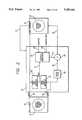
- a broadcaster 22plays back and broadcasts an encoded program segment, e.g., a commercial advertisement or an entire program, for receipt and processing by a monitoring station 24.
- the broadcasterincludes a tape player 26 for playing back an encoded master tape 28 that contains the encoded program segment, and further includes a transmitter 30 and an associated transmitting antenna 32 for transmitting the played back signal.
- the transmitted signalcan be received at a plurality of locations throughout its broadcast range by standard broadcast receivers (not shown).
- the monitoring stationreceives the transmitted signal through a receiving antenna 34 and decodes the transmitted signal, to identify the encoded program segment.
- the encoded submaster tape 28is specially generated to contain identifying data within an encoded audio channel.
- the stationstores reference information, indicating the identification of the encoded program segment and its time of receipt. Periodically, the monitoring station transmits this reference information along a communication path 36 to a central computer 38, where it is compared with the agreed-upon broadcast schedule to compile a confirmation/discrepancy report.
- the encoded submaster tape 28is a specially adapted copy of an original program segment, e.g., a commercial, which has been modified to contain encoded data that identifies the original program segment and its prescribed duration.
- the original program segmentis modified by adding the encoded data in a manner that is substantially undetectable to a normal viewer of the encoded program segment.
- a substantially inaudible encoded signalis added to a notched-out portion of an audio channel of the original program segment.
- the encoded signalis made up of a succession of encoded data frames.
- Each encoded data framehas a defined format and includes: 1) a synchronization field to identify the frame's beginning, 2) a duration field to identify the program segment's expected duration, 3) a program segment identification field to identify the original program segment, 4) a sequence code field to identify the sequence of the encoded data frames, 5) a parity bit to verify data integrity, and 6) a terminator pattern to identify a truncated, encoded program segment.
- the encoded data framesare repeated a plurality of times within each encoded program segment.
- the monitoring stationuses the sequence code field to identify the relative temporal position of each encoded data frame that is received within each encoded program segment. This format permits the monitoring station 24 to determine a proper time period to monitor the encoded program segment, even when one or more encoded data frames might be missing, and it also permits detection of encoded program segments that are truncated.
- the monitoring station 24will be able to retrieve the encoded data frame from the encoded program segment and use this data to confirm that the encoded program segments were properly broadcast according to an agreed-upon broadcast schedule.
- FIG. 2there is shown a block diagram of an encoding station 40 that cooperates with a tape player 42 and a tape recorder/player 44 to generate the subencoded master tape 28.
- An original program segment tape 46containing the original program segment, is copied from the tape player to the tape recorder/player under control of the encoding station.
- a video signal supplied on line 48 from the tape playeris input without modifications to the tape recorder/player.
- An audio channel signal supplied on line 50 from the tape playeris input to the tape recorder only after it first has been modified to add encoded data. This modification is performed by an encoder/modulator 52, which generates an encoded audio signal on line 54 that includes one or more encoded data frames.
- Each encoded data frameis a fixed block of data, 7.5 seconds long, which is generated one or more times within the encoded program segment.
- a program segment identification signalis supplied on line 56 to the encoder/modulator 52, to identify the original program segment, and a time duration signal is supplied on line 58 to the encoder/modulator, to identify the prescribed duration of the original program segment. This program segment identification and time duration identification is encoded into each encoded data frame.
- the encoded datais limited to a small section of the audio spectrum so that this modification of the audio channel signal is substantially undetectable to a listener. More particularly, a notch filter 60 removes a portion of the audio channel's signal supplied on line 50 and generates a notched audio signal on line 62.
- An adder 64adds the notched audio signal to the encoded audio signal supplied on line 54 from the encoder/modulator 52, to form an encoded audio output signal on line 66.
- the encoder/modulatormodulates data to generate the encoded audio signal by using a fixed number of cycles of a fixed modulation frequency to represent each bit of data. The modulation technique used is phase-shift keying or PSK, as described below.
- This encoded audio output signalis supplied on line 66 to the tape recorder/player 44, which records it on the encoded submaster tape 28.
- Encodingbegins when either a video signal or an audio signal is first detected from the original program segment tape 46 when it is played back on the tape player 42.
- a video start detector 68monitors the video signal supplied on line 48
- an audio start detector 70monitors the audio signal supplied on line 50.
- the purpose of the start detectorsis to synchronize encoded and modulated data from the encoder/modulator 52 with the beginning of the encoded program segment. This is desirable for two reasons. First, measurements in the monitoring station 24 correspond to the beginning of the first encoded data frame, since the monitoring station assumes that the first encoded data frame also corresponds to the beginning of the encoded program segment.
- the video start detector 68delays for no more than 1/60 second following an initial detection of the video signal supplied on line 48 before generating a start signal on line 72.
- the audio start detector 70delays for no more than 1/60 second following an initial detection of the audio signal supplied on line 50 to generate the start signal. This worst-case time delay corresponds to one half of the duration of a video frame.
- the encoder/modulator 52commences generating the encoded audio signal immediately upon receipt of the start signal.
- the tape recorder/player 44plays back the encoded submaster tape 28 to generate a tape output signal on line 74.
- the encoding station 40processes the tape output signal, in a manner similar to that described below for the monitoring station 24, to confirm that 100% of the data can be successfully retrieved.
- the encoded master tapeis available for duplication and distribution to the broadcasters.
- the encoded program segmentcan be directly broadcast, without making a recorded copy.
- a local computer 76accumulates received data and other related data and stores this data within a local memory 78 that can be RAM, disk, or any other type of computer-accessible memory. Included in this data is an identification of which station broadcast each encoded program segment that has been detected, the identity of the original program segment, its expected duration, corresponding audio and video quality indications for the expected duration, and the receipt time and date for the encoded program segment.
- the local computeruses a modem 80 to securely send the contents of the local memory across the communication path 36 to the central computer 38. Techniques, well known in the art, are used to insure the receipt of correct data without corruption due to signal noise or modifications by potential intruders.
- the data stored in the local memory 78is derived from various sources.
- the identification of the original program segment and its expected durationis derived from the encoded data frames received from within each encoded program segment.
- the monitoring station 24also accumulates other data, such as the audio and video quality indications and the receipt time and date, by monitoring internal monitors while receiving the encoded program segment.
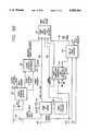
- the monitoring station 24includes a plurality of station processors, two of which are shown at 82 and 84.
- a tuner 86is used within each station processor for monitoring a separate broadcast or cable station. All of the station processors are connected to the local computer 76.
- the local computeris preprogrammed to instruct each tuner, using station select control lines 88 and 90, to monitor a particular station. These preprogrammed selections are stored as channel identification data within the local memory 78.
- the encoded signalpreviously added to the original program segment, contains unique program segment identification data, which is used to reference the data accumulated in the local memory 78. Also, within this encoded signal is data that corresponds to the expected duration of the original program segment. This data is used to set a time limit on video monitoring by the station processors 82 and 84. For example, when an encoded program segment is received and identified as having a 15-second duration, a video quality detector 92 will monitor the encoded program segment for this 15-second time period.
- a received video signalis supplied on line 94 from the tuner 86, which extracts this video signal from the encoded program segment.
- the video quality detectormonitors both the sync level amplitude and the black/white or composite video levels of the received video signal to generate video quality data. Additionally, the video quality detector retains a number of seconds of the video quality data as past-history data. This past-history data is required since 7.5 seconds are required to receive a complete encoded data frame from within an encoded program segment. Thus, when a complete encoded program segment is received, the corresponding past-history data from the video quality detector must be retrieved to match the actual beginning of the encoded program segment.
- the video quality detectoroutputs a signal indicative of the detected quality, for coupling on line 93 to the local computer 76.
- a plurality of encoded data framesgenerally are sent for each encoded program segment. Whenever an encoded data frame is successfully received, it can be used as a status indication that the quality of the audio signal on the encoded audio channel was satisfactory for the prior 7.5 seconds. Thus, this status indication is stored in the local memory 78 for the corresponding encoded program segment.
- a real-time clock 96 within the local computer 76maintains a time reference.
- a reference clock 98maintained in synchronization with a national standard, e.g., WWV, is interfaced to the central computer 38.
- the central computercommunicates along the communication path 36 with the monitoring station 24 via the modem 80 and instructs the local computer to synchronize its real-time clock with the reference clock.
- the local computerfetches the time and date from the real-time clock and time-stamps received data in the local memory 78 to correspond to this time and date.
- the retrieved timeswill correspond to a common reference and can then be used to confirm a precise broadcast time for each encoded program segment.
- a digital signal processor or DSP 100which is a digital computer with analog and digital input and output capability, is used to permit sharing of sections of the hardware that form the station processors.
- DSP 100allows analog-type functions, such as bandpass filtering, to be shared between station processors and modified under software control. Additionally, other functions can be time-shared between broadcast channels.
- the DSP implementationis preferred, the present invention also encompasses conventional implementations of the functional blocks shown in FIG. 3. However, independent of the implementation, some elements such as the tuner 86 and the video quality detector 92 must be duplicated for each station processor.
- Broadcast signals from television, radio or cable stationsare input to the monitoring station 24 through the tuner 86.
- the local computer 76uses the station select controls 88 and 90 to instruct each tuner which station to monitor.
- the tuneroutputs the received video signal on line 94 to the video quality detector 92.
- the tuneralso outputs a received audio signal, which corresponds to the encoded audio signal containing the phase-modulated digital data.
- the station processor 82further processes this received audio signal to demodulate and decode the data and to transmit that data to the local computer 76.
- the station processor 82suitably processes the received audio signal using the DSP 100.
- the signal processing functionsare shown in FIG. 3 to include a bandpass filter 104, a demodulator and decoder 106, and a data message memory 108.
- the bandpass filterreceives the received audio signal on line 102, and its bandwidth is centered at 42 Hz, which is the center frequency of the modulated data, so as to remove all but that modulated data.
- the filtered audio signalis supplied on line 110 to the demodulator and decoder 106, which demodulates the modulated data to generate a corresponding binary data stream. That binary data stream is transmitted on lines 112 to the data message memory 108, which in turn transmits the data stream on line 114 to the local computer 76.
- the demodulator and decoder 106also generates several feedback control signals for controlling the tuner 86, the bandpass filter 104, and the video quality detector 92.
- a gain control signalis supplied on line 110 to the tuner, to adjust the amplitude of the received audio signal to a standard value.
- a control signalis supplied on line 118 to the bandpass filter, to controllably adjust its center frequency so as to maximize the amplitude of the filtered audio signal.
- a segment start time signalis supplied on line 120 to the video quality detector 92, to instruct the video quality detector when to begin monitoring video quality.
- each station processor 82, 84that is implemented by the digital signal processor (DSP) 100 is described more particularly with reference to FIGS. 4 and 5.
- FIG. 4depicts one suitable configuration for the DSP, configured as a peak detection decoder 122
- FIG. 5depicts an alternative configuration for the DSP, configured as a correlation detection decoder 124.
- the DSPof course, is implemented in software
- FIGS. 4 and 5are shown as conventional hardware block diagrams that are the functional equivalent of the DSP software. These hardware equivalents are considered preferable for explanatory purposes.
- the peak detection decoder 122is shown to receive the program audio signal on line 102 and to initially filter that signal in the bandpass filter 104. This passes the encoded signal, but filters out nearly all of the remaining audio.
- a symbol energy detector 126receives the filtered program audio on line 128 and measures its energy over a symbol period. If the energy exceeds a predetermined threshold, the detector outputs an above-threshold signal on line 130. Conversely, if the detected energy is measured to be below that threshold, the detector outputs a below-threshold signal on line 132.
- An amplitude detector 134receives both the below-threshold signal on line 132 and the filtered program audio signal on line 128, and it generates an above-threshold signal when the filtered program audio signal first exceeds a predetermined threshold. This, of course, ordinarily occurs at the beginning of each data frame, which in the preferred embodiment includes a sequence of 4 null symbol bits, followed by 11 sync-up symbol bits.
- the above-threshold signal produced by the amplitude detector 134 at the beginning of each data frameis transmitted on line 136 to a peak amplitude detector 138.
- the peak amplitude detectorbegins monitoring the encoded tone signal present on line 128, and it outputs a mark pulse signal each time a positive peak is detected in the encoded tone signal.
- the frequency of these mark pulsescorresponds to the frequency of the encoded tone signal.
- the mark pulsesare supplied on line 140 to a tone frequency detector 142, which measures the time duration between five successive mark pulses and calculates the tone frequency. Timing signals supplied on line 144 from a master clock 146 are used in performing this calculation.
- the tone frequency detector 142transmits the calculated tone frequency and an acceptable range signal on lines 148 and 150, respectively, to a register 152. If, on the other hand, the tone frequency detector determines that the calculated tone frequency is outside the acceptable range, the detector outputs a reset command for transmission on line 154 to several circuits in the peak detection decoder 122, one such circuit being the register 152.
- the mark pulses present on line 140also are transmitted to a peak counter 156, which provides a running count of the number of peaks received during the current symbol period.
- This peak countis transmitted on line 158 to a phase-shift detector 160, which receives the count and compares it with time signals received on line 146 from the master clock 144.
- the phase-shift detectorcompares the actual receipt time of each pulse count with a predicted receipt time it has calculated and, if the actual count is received later than the predicted count by more than a predetermined threshold, then it determines that a 180-degree phase shift has occurred.
- a symbol boundaryis established when two successive alternating symbol bits have been detected, i.e., either a 010 or a 101.
- a symbol boundary detector 162receives mark pulses on line 164 from the phase-shift detector 160, which indicate the occurrence of a 180-degree phase shift in the received tone signal.
- the symbol boundary detector 162also receives timing signals on line 146 from the master clock 144 and, based on those inputs, determines when two successive alternating symbol bits, i.e., either 010 or 101, have occurred.
- the symbol boundary detector 162also determines that a symbol boundary has occurred based on a predicted symbol period, with no 180-degree phase shift having been detected. This latter determination occurs when two successive symbol bits are of the same polarity.
- the symbol boundary detector 162then outputs a pulse on lines 166 and 168 each time a symbol boundary is determined to have occurred.
- a symbol counter 170receives the pulses on line 166 from the symbol boundary detector 162 and maintains a running count on the number of symbol boundaries that have occurred since last being reset. This count is reset to 0 upon receipt of reset command from either the tone frequency detector 142, discussed above, or from an end-of-frame detector 172, discussed below.
- a symbol bit sign detector 174receives the pulses on line 168 from the symbol boundary detector 162, and it also receives mark signals on line 164 from the phase-shift detector 160 each time a 180-degree phase shift has been detected. If both pulses are received simultaneously, then it is determined that a sign change has occurred; otherwise, it is determined that the sign has remained the same.
- the symbol bit sign detector 174outputs on line 176 a signal indicating the sign of the current symbol bit. This signal is clocked into a frame bit buffer 178 by pulses received on line 180 from the symbol counter 170.
- the current symbol countcontrols the bit position of the frame bit buffer 178 into which the current symbol value is stored.
- the frame bit bufferis cleared to 0 when a reset command has been received.
- a frame sync-up detector 182monitors the bits stored in the frame bit buffer 178 and compares those bits with a predetermined, stored bit pattern. When the bit patterns match each other, the frame sync-up detector determines that frame sync-up has occurred and outputs a frame sync-up signal on line 184.
- the peak detection decoder 122monitors the time duration in which the symbol energy exceeds a predetermined threshold, so that an indication of the receipt of a signal can be made even though synchronization has not been achieved. This is accomplished using an above-energy threshold time detector 186, which receives the above-threshold signal on line 130 from the symbol energy detector 126, as well as timing signals on line 146 from the master clock 144. The detector 186 provides a running count of the time in which symbol energy has been determined to be above the predetermined threshold. This running count is a measure of the frame duration and is useful when either a head cut or a tail cut has occurred. This count is reset upon receipt of a frame sync-up signal on line 184 or upon receipt of a reset signal on line 154.
- the end-of-frame detector 172monitors the actual symbol count signal received on line 180 from the symbol counter 170, as well as the symbol count estimate received on line 188 from the above-energy threshold time detector 186, so as to determine when the end of the current data frame has occurred. This determination also is made upon receipt of a below-threshold signal on line 132 from the symbol energy detector 126. A reset command is output on line 154a when an end-of-frame has been detected. At the same time, an end-of-frame signal and the symbol count estimate are transmitted on lines 190 and 188, respectively, to a frame data buffer and uploader 192.
- this buffer and uploaderare also supplied to this buffer and uploader.
- the frame sync-up signal on line 184 from the frame sync-up detector 182the frame bit data on line 194 from the frame bit buffer 178, and a measure of the tone frequency on line 196 from the tone frequency measurement register 152.
- This accumulated datais output periodically on lines 198.
- FIGS. 5A and 5B togetherare a simplified block diagram of a correlation detection decoder 124, which is a suitable alternative to the peak detection decoder 122 of FIGS. 4A and 4B. Again, this decoder is preferably implemented in a digital signal processor, and the block diagram of FIGS. 5A and 5B represents a hardware equivalent to the preferred software implementation.
- the correlation detection decoderis similar in many respects to the peak detection decoder, and similar blocks are identified using the same reference numerals, but accompanied by a symbol. The primary difference between the two decoders lies in the initial detection of the incoming encoded tone signal.
- the program audio signal received on line 10is initially filtered in a bandpass filter 104', to remove most of the audio and pass just the encoded tone signal.
- This encoded tone signalis transmitted on line 128' to a correlator 200, which correlates the tone signal with a locally-generated tone signal received on line 202 from a frequency generator 204.
- the frequency of the locally-generated signalis controlled by an appropriate feedback signal supplied on line 206.
- the correlator 200integrates the crosscorrelation of the two incoming signals beginning from a 0 value, when reset by a reset command supplied on line 154'.
- the correlation valueis transmitted on line 208 to a phase-shift detector 210.
- the correlation valueWhen a phase shift in the encoded tone signal occurs, the correlation value will change its polarity or sign, and the integrated correlation value will begin ramping in an opposite direction from its prior direction. This direction change provides a basis for phase-shift detection. As previously mentioned, the initial 8 bits in each frame alternate in value, so a phase shift will occur at the end of each bit.
- the correlation detection decoderis configured such that a difference as high as 5% between the frequencies of the encoded tone signal and the locally-generated tone signal will cause a reduction in the maximum correlation value of only 20%.
- an above-threshold signalis transmitted on line 212 to the phase-shift detector 210, to initiate the phase-shift detection process.
- This signalalso is supplied to an above-correlation threshold time detector 214, to activate the symbol count estimation process, in similar fashion to the corresponding block of the peak detection decoder of FIGS. 4A and 4B.
- the correlator 200transmits a below-threshold signal on line 132' to an end-of-frame detector 186', to indicate that the end of the frame has been detected.
- the phase-shift detector 210is activated by the above-threshold signal received on line 212 of the correlator 210, and it then monitors the correlation signal received on line 208 to detect a sign change in that value. If a sign change is detected, that represents a 180-degree phase shift in the encoded tone signal, and the phase-shift detector 210 marks that occurrence by outputing a mark pulse on line 216. Such pulses correspond to the mark pulses present on line 164 in the peak detection decoder 122 of FIG. 4.
- the mark pulses present on line 216are supplied to a symbol boundary detector 162', which also receives timing signals on line 146' from a master clock 144'. Based on these two inputs, the symbol boundary detector outputs a mark pulse at the end of each detected symbol. In addition, the symbol boundary detector 162' calculates the tone frequency value for the current symbol bit and compares that value with the value for the previous symbol bit. If the two are substantially the same, it is determined that the locally-generated tone frequency has the correct tone frequency and no adjustment is made to the feedback control signal being supplied by the symbol boundary detector 162' to the frequency generator 204. On the other hand, if the calculated tone frequency value for the current bit is determined to be different from that of the previous bit, an appropriate adjustment is made to the feedback control signal. In this way, loop stabilization can be achieved within 8 symbol bit periods for an initial frequency difference as high as 5%.
- the mark pulses output by the symbol boundary detector 162'are transmitted on line 168' to a symbol frequency detector 218, which measures the time delay between successive mark pulses. Based on that measurement, it calculates the tone frequency and determines whether or not that calculated tone frequency is within an acceptable range.
- the symbol frequency detector 218corresponds to the tone frequency detector 142 of FIG. 4A, except that the mark pulses it receives represent symbol boundaries rather than tone frequency peaks. Consequently, a mere scaled adjustment needs to be made.
- the remainder of the correlation detection decoder 124 of FIGS. 5A and 5Bare substantially identical in structure and function to the corresponding portion of the peak detection decoder 122 of FIGS. 4A and 4B.
- the symbol bit sign detector 174', symbol counter 170', frame bit buffer 178', frame sync-up detector 182' end-of-frame detector 172', and frame rate buffer and uploader 192'all correspond to the correspondingly named blocks of FIG. 4.
- FIGS. 6A-6Cthere are shown multiple representations of binary digits or bits comprised of a plurality of cycles of the modulation frequency of a phase-shift keyed or PSK signal.
- a first phase of the modulation frequencyis chosen to represent a 1 or mark bit while a second phase of the modulation frequency represents a 0 or space bit.
- a plurality of cycles of the modulation frequencyare employed to diminish the spread of harmonics.
- a modulation carrier frequency of 42 Hzis selected. This frequency is below 50 Hz, a required minimum audio response frequency for a television or FM radio station. Consequentially, most of the audio spectrum of original program segments is above 50 Hz. Since broadcasters differ in their performance below this required minimum audio response frequency, the choice of 42 Hz was made to correspond to a typical minimum audio response, as measured from a group of broadcasters.
- a modulation rateis chosen that represents each bit with an integral number of cycles of the modulation frequency. This is referred to as N-cycle modulation. In N-cycle modulation, 5 cycles of the modulation frequency represent each bit, achieving a bit rate of 42/5 or 8.4 bps.
- the modulated signalwill not significantly interfere with the audio content of the original program segment, which is above 50 Hz. Additionally, since a normal listener is less sensitive to lower frequencies, it is not believed that a normal listener will hear the modulated signal.
- FIG. 6A5 cycles of the first phase of the modulation frequency are shown, corresponding to a 1 or mark bit.
- FIG. 6Bshows 5 cycles of the second phase, corresponding to a 0 or space bit.
- Each bitis generated by a sinusoidal sequence where the opposite bit is generated by the identical sequence multiplied by -1, corresponding to a phase shift of 180°. The significance of this phase definition is illustrated below.
- the value of the modulated signal at a transition point 232, the end of each bit representation,is zero, referred to as a zero crossing. Consequently, transitions between the two phases will always occur between two signals of opposite phases but with an identical transition value of zero, thus minimizing the harmonic content of the modulated signal above the modulation frequency.
- the four potential bit transitions of 1-1, 1-0, 0-0, and 0-1are illustrated. Since all patterns are uniquely identifiable and, since all bit transitions occur at a bit transition point 234, corresponding to a zero crossing, the magnitude of the harmonics are minimized.
- N+1/2-cycle modulationan alternative technique of generating a PSK signal is shown, referred to as N+1/2-cycle modulation, where an additional 1/2 cycle is used for each bit time period.
- an integral number of half cycles of the modulation frequencyis used to represent each bit.
- bit duration of 51/2 cyclesa bit rate of approximately 7.63 bps is attained.
- the significance of this alterationis not found in the minor bit rate or spectrum alterations, but instead is found by reference to the bit transition diagrams of FIG. 7C.
- the pattern associated with each phaserecommences at each bit transition point 236.
- this technique's sensitivity to bit transitions of the datahas been altered.
- the demodulator 114To demodulate a PSK encoded signal, the demodulator 114 must detect the modulation frequency, the bit rate, and the bit transitions. Since PSK uses only a single carrier frequency, the modulation frequency is relatively simple to detect. In the system of the present invention, the bit rate is defined between the encoder/modulator 52 and the demodulator. However, bit transitions must still be detected to reliably sample the received audio signal on line 102. To determine the proper sampling point, an identifiable synchronization pattern must exist that provides sufficient detectable bit transitions. In the first PSK modulation technique, this requires sufficient 1-0 and 0-1 transitions in the synchronization pattern. However, with the alternative technique, such a pattern would not generate any bit-timing information. Instead, with this alternative technique, sufficient 1-1 or 0-0 transitions are required to detect the bit timing. Thus, selection of the synchronization pattern is dependent upon the chosen modulation technique.
- NNNN11111110101For the system of the present invention, the following synchronization pattern has been chosen: NNNN11111110101, where N signifies a null or the absence of the modulation frequency, 1 signifies a mark or a first phase of the modulation frequency, and 0 signifies a space or a second, opposite phase of the modulation frequency. Since this pattern contains 1-1 transitions, as required by the N+1/2-cycle modulation technique, and 1-0, 0-1 transitions, as required by the N-cycle modulation technique, this pattern will function with either of the modulation techniques. For a less generalized synchronization pattern, NNNN1111111 could be used for N+1/2-cycle modulation and NNNN101010 could be used for N-cycle modulation.
- a systemcan miss the synchronization pattern and attempt to erroneously synchronize on data within a message. If a false sync is achieved, false data will be decoded.
- Various functions, such as parity detection,can help avoid processing false or corrupted data.
- a one-bit parity checkis part of the system of the present invention.
- the capability of a one-bit parity checkis limited since an error of two or more bits is undetectable. Thus, it is desired that this synchronization pattern not be reproducible within the message's data content to insure that false synchronization will never occur.
- a standard character setsuch as ASCII
- ASCIIcan reproduce the synchronization pattern. For instance, presuming that the most significant bit is sent first, the 7-bit ASCII character string ⁇ Ou ⁇ is represented as 10011111110101. The last eleven bits of this pattern are identical to the synchronization pattern. If a synchronization detector did not require detection of the null bits or if the synchronization detector erroneously detected null bits, this ASCII pattern could be falsely detected as the synchronization pattern.
- synchronization detectionrequires the detection of at least one of the null bits.
- a character encoding schemeis chosen that permits sufficient combinations for all required data characters, but excludes the possibility of any binary pattern duplicating the synchronization pattern.
- Table Ia table is found of character representations for the system of the present invention.
- This tablecontains encoding possibilities for 7-, 6-, 5-, 4-, and 3-bit characters.
- the entries for this tableare chosen such that no character combination can reproduce the synchronization pattern. This is accomplished by excluding certain bit patterns, resulting in an encoded character set that can generate no more than 6 consecutive 1's or 0's.
- this tableis useful in preventing duplication of the NNNN11111110101 synchronization pattern, which can be used both with N-cycle and N+1/2-cycle modulation. Additionally, this table can be used with the NNNN1111111 synchronization pattern for N+1/2-cycle modulation.
- Table IIshows a table containing encoding possibilities for 7-, 6-, 4-, and 3-bit encoded characters where no more than 6 alternating 1's and 0's may occur.
- this tableis useful in preventing duplication of the previously mentioned NNNN101010 synchronization pattern for N-cycle modulation.
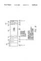
- each encoded data frameis divided into seven message fields, each performing a prescribed function.
- the combined size of the seven fieldsis 63 bits.
- the frame rateis 63/8.4 or 7.5 seconds per frame.
- an encoded program segmentis sufficiently long for a plurality of encoded data frames to be transmitted.
- the first message fieldis a synchronization field 238.
- the first modulation techniqueuses the following 15-bit tertiary synchronization pattern: NNNN11111110101, which is uniquely identifiable by the demodulator and decoder 106.
- the synchronization fieldmight also be described as being comprised of 4 bits of leading nulls followed by an 11-bit binary synchronization pattern.
- This synchronization patternaccomplishes two main functions. First, the synchronization pattern is used to adapt the demodulator and decoder 106 and to optimize the bandpass filter 104 to the actual modulation frequency. Second, detected phase transitions within the synchronization pattern are used to adjust sampling of the peak receive output signal supplied on line 128. These functions both optimize the noise immunity and improve the demodulation performance of the system.
- the 1-0 combination used for this synchronization patternis unique due to the bit encoding used for each character and cannot be reproduced by the data content of any possible encoded data. Additionally, since the leading null bits are not present elsewhere within the data message, the null bits can be used to detect head-cuts, as discussed below.
- the next fieldis a 3-bit message type field 240. Since various types of encoded program segments are possible, this field permits the monitoring station 24 to distinguish between them. Six variations are permitted, as listed in FIG. 8. This field, as well as all other fields, are encoded according to Table I to avoid inadvertent generation of the synchronization pattern.
- the next fieldis a 3-bit duration field 242 that identifies the prescribed duration of the encoded program segment. These durations correspond to the predominantly used commercial lengths.
- the monitoring station 24is notified of the expected encoded program segment duration, and determines a time period during which data is accumulated from the video quality detector 92. Additionally, the successful receipt of each encoded data frame is also noted during this time period. Even if one of the plurality of encoded data frames is not successfully received, the system of the present invention can still generate useful information. These failure modes are discussed below.
- the next fieldis a 36-bit program segment identification field 244, which is four alpha characters followed by four numeric characters.
- This 8-character sequenceis a unique character sequence, which is used to identify a particular original program segment for a commercial. Since the encoding of this data is done using Table I, each alpha character requires 5 bits and each numeric character requires 4 bits and thus, 36 bits in total.
- the monitoring station 24Upon receipt of the program segment identification field, the monitoring station 24 references any accumulated data to this field in the local memory 78.
- the next fieldis a sequence code field 146 that contains a 2-bit sequence code. Whenever possible, the encoded data frame repeats within the encoded program segment. Thus, for a 15-second encoded program segment, the 7.5-second encoded data frame will be transmitted twice. Suppose that the first frame was not successfully received. Then, without this sequence field, the monitoring station 24 would only commence accumulating data as of the second encoded data frame, 7.5 seconds into the encoded program segment. This data, by itself, would not be useful without a unique sequence code to designate that this data was from the second encoded data frame. With this additional information, the monitoring station could then determine that an encoded program segment had actually commenced 7.5 seconds before the start of the current encoded data frame and could thus monitor a proper time period. Also, since the video quality detector 92 retains past-history data, this field permits a maximum amount of useful status data to be associated with a received encoded program segment.
- the sequence fieldis limited to 2 bits and thus can only represent four potential modular combinations or sequences.
- the effect of this limited modular representationis only seen when a message duration of greater than 30 seconds is required.
- the next encoded data frame sequence numberwill again cycle back to modular sequence number zero. Unless four consecutive encoded data frames are lost, this modular sequence number will be sufficient to identify the actual relative sequence of the received encoded data frames. Since a loss of four consecutive encoded data frames is not likely, this limitation is considered insignificant.
- the next data fieldis a 1-bit parity check field 248, which checks the parity of the entire encoded data frame.
- the usefulness and deficiencies of a single-bit parity checkare well known to one of ordinary skill in the art. However, since a multiple-bit error is undetectable, the system of the present invention can optionally take advantage of the plurality of encoded data frames to provide additional data verification since each encoded data frame is only distinguished by its sequence field 246.
- the last data fieldis a terminator pattern 250 consisting of 3 bits of trailing nulls, which are solely used to confirm the end of the encoded data frame and to identify tail-cuts. Tail-cuts are discussed below.
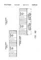
- FIGS. 9A-9Cthere are shown examples of interactions between encoded data frames of a plurality of commercial encoded program segments.
- only one commercial encoded program segmentwould be broadcast in any one time period, eliminating any potential overlap between program segments.
- more than one program segmentis normally broadcast each time period and thus it is desirable to detect any overlap that might occur.
- a plurality of commercial encoded program segmentsare broadcast sequentially, resulting in a condition referred to as a run-in. This is a normal condition that occurs when the trailing nulls of a last encoded data frame of a first encoded program segment immediately precede the leading nulls of a first encoded data frame of a next encoded program segment.
- this normal run-in conditionshown in FIG. 9A, seven nulls will be consecutively broadcast, i.e., three trailing nulls followed by four leading nulls.
- this normal run-in conditionmight not always occur, resulting in head-cut and tail-cut conditions. These conditions occur when the beginning or end of an encoded program segment is lost due to the existence of another encoded program segment that is prematurely or belatedly broadcast.
- head-cutas shown in FIG. 9B, the leading nulls and the synchronization pattern can be lost due to the overlapping broadcast of the prior encoded program segment. Since more nulls exist than are absolutely required by the synchronization detector 120, a minimal head-cut can be tolerated and just noted by the monitoring station 24. However, a larger head-cut will not permit recognition of the synchronization pattern and thus, encoded data frame 1 of the second encoded program segment will not be detectable.
- encoded data frame 2 of the second encoded program segmentwill still be detected and identified. Since encoded data frame 2 still identifies the original program segment identification, its duration, and the sequence number, the monitoring station 24 will still identify the proper monitoring period for the second encoded program segment. However, the monitoring station will additionally note that a head-cut did occur in data stored in the local memory 78. In this particular case, the monitoring station will determine that encoded program segment 2 had commenced 7.5 seconds before the start of the detected encoded data frame, encoded data frame 2, since its sequence number would denote that it was the second encoded data frame.
- Tail-cutsare processed in a similar manner.
- a tail-cutwill occur, as shown in FIG. 9C, when a second encoded program segment is broadcast before the end of the first encoded program segment, overlapping a first encoded program segment. Again, a minimal amount of detection tolerance is provided due to the surplus of nulls. However, should any additional trailing amount of the last encoded data frame of the first encoded program segment be lost, the data content of that encoded data frame will be affected and this last encoded data frame will not be decodable. Providing that this was not the only encoded data frame, e.g., when the encoded program segment was 15 seconds or more, the prior encoded data frames will still identify the particular encoded program segment. However, the monitoring station 24 will additionally note that a tail-cut was detected.
- a unique conditionoccurs when an encoded program segment is only 10 seconds long, since a 10-second encoded program segment is not an integral multiple of the 7.5-second duration of an encoded data frame. Since only complete encoded data frames can be broadcast, only a single encoded data frame can be used in this case. The single encoded data frame begins at the start of the 10-second segment, and it is followed by the first 2.5 seconds of a second encoded data frame. Counting the number of bits in the decoded partial second data frame provides a measure of its length, so that the program segment's intended 10-second duration can be verified.
Landscapes
- Engineering & Computer Science (AREA)
- Signal Processing (AREA)
- Multimedia (AREA)
- Computer Security & Cryptography (AREA)
- Business, Economics & Management (AREA)
- Marketing (AREA)
- Databases & Information Systems (AREA)
- Television Systems (AREA)
Abstract
Description
This invention relates generally to systems that identify program segments broadcast by radio, television, or cable broadcasters and specifically to systems that identify and verify the integrity of the program segments, e.g., commercial advertisements or entire programs, using a superimposed frame of encoded data.
Commercial broadcast systems get their name, in part, due to the presence of commercials. Although distasteful to many, commercials are essential for television and radio broadcasters to generate the vast majority of their income. Even cable systems, which originally earned their reputations as being commercial-free alternatives, have quickly followed suit due to the significant income potential. Commercials provide name recognition to advertisers, enabling them to sell more of their products, and aid the advertisers to quickly generate a demand for new products and to test new marketing approaches. Thus, commercials have a substantial value to both the broadcasters and the advertisers.
Advertisers are willing to pay sizable sums of money only if broadcasters timely and completely broadcast their commercials. Many reasons exist for the advertiser's strict demands. For instance, an advertiser might be doing a time-limited sales campaign. If a particular commercial was broadcast after the end of such a sales campaign, this broadcast probably would be useless. Advertisers also target certain audiences and will pay significant premiums for a commercial broadcast within a program that captures a desired group of viewers. Thus, time or date shifting is not acceptable for a commercial. Additionally, commercials are carefully composed to be watched (or at least shown) in their entirety. Thus, a truncated broadcast of a commercial or one with audio or video dropouts is potentially useless.
Despite all well-intentioned efforts, commercials are sometimes broadcast at a wrong time, truncated, or broadcast with dropouts or other degradations. To receive payments from the advertisers, broadcasters generally must certify that each advertiser's commercial was timely and completely broadcast. Currently, this certification is manually performed.
Many attempts have been made to automate the identification of various program segments such as commercials. An ideal system would identify any and all program segments and correlate them with the appropriate advertisers without requiring any pre-processing efforts by either the advertisers or the broadcasters. Also, an ideal system would not alter or degrade the audio or video signals associated with each program segment. Such a system would need to correlate vast amounts of video and/or audio data to recognize each particular program segment.
Consequentially, such a system would also be highly susceptible to video or audio noise that intermittently could cause it to fail to recognize a program segment. Also, since the processing and storage requirements for such a system would be astronomical, such systems are not believed to be currently commercially feasible. Some systems have attempted to minimize these requirements by inserting cue sequences into the program segment to forewarn pattern recognition circuitry. Such a cue might be a blank video frame or a peculiar type of fade sequence. This type of alteration to the content of a program segment generally is not desirable.
Other systems have approached this task by encoding data within the video lines of the program segment. These systems generally use a particular line within the vertical blanking interval and thus outside the viewable image. Since these systems require high frequency processing and precise timing to encode and decode this data, they are not believed to have been commercially successful. Additionally, since these systems require a video channel, they can be used only with television and not radio broadcasters.
Other systems have combined modulated data with the audio channel of the program segment. Some of these systems have notched out sections of the audio channel within the range of human hearing and FSK-encoded data using audible frequencies with amplitudes that are substantially inaudible to the typical listener. In one system, a subaudible (below the nominal frequency range of human hearing) frequency band was chosen to encode the identification data and on-off keying of a fixed modulation frequency was used to designate the binary data content. Such a system is believed to have an undesirable amount of noise susceptibility, because it is not possible to differentiate between the absence of a modulation frequency and an off-keyed modulation state.
As previously discussed, program segments, in addition to not being broadcast at the proper time, might be truncated. It is still desirable to recognize a program segment, even when truncated. However, if a data encoding system required the full duration of the program segment to communicate the program segment's identity and duration, such a system would be too susceptible to errors.
It should therefore be appreciated that a need exists for a practical and thus marketable system to encode data onto the audio channel of a program segment with an encoding technique that is acceptably immune to noise and program segment truncations such that the system can still identify the program segment and determine its duration despite audio dropouts and program segment truncations. The present invention satisfies these needs.
Briefly, and in general terms, the present invention is embodied in a system that generates one or more encoded data frames that are added to an original program segment, e.g., a commercial or an entire program, to form an encoded program segment, where each encoded data frame identifies the original program segment and its prescribed duration. The encoded program segment is then broadcast by a television, radio or cable broadcaster. Upon receipt of the encoded program segment by a monitoring station, the encoded data frame extracted and is used to identify the program segment and its duration even when one of the encoded data frames is received with errors.
More specifically, the encoded data frame starts with a synchronization pattern and includes data that identifies the particular encoded program segment and its prescribed duration. Additionally, the encoded data frame includes a sequence code and a parity bit that are used to further detect and correct for broadcast errors. The encoded data frame is modulated and added to an audio channel of the original program segment. The modulation is performed using an integral number of whole or half cycles of a modulation frequency to represent each bit. Phase-shift keying (PSK) modulation is preferred.
The beginning and end portions of each encoded data frame include null bits, represented by the absence of the modulation frequency, which are used to detect error conditions where the beginning or the end of the encoded program segment is truncated. A plurality of encoded data frames are added, whenever possible, to the original program segment, to provide redundancy. This redundancy, in addition to aiding the monitoring station to detect encoded program segments that are truncated, also permits detection of audio dropouts within the encoded program segment. A video quality detector is also used to detect video dropouts during the broadcast of the encoded program segment.
An encoding station generates the encoded data frames and adds them to the original program segment to form the encoded program segment. An identification code and a prescribed duration are input to the encoding station, which uses this data to generate the encoded data frames. Encoding commences after either audio or video circuitry in the encoding station detects the presence of an audio or a video signal being played back from the original program segment. An integral number of encoded data frames are then added to the original program segment, limited by the duration of the original program segment as defined by a prescribed duration input. The encoded program segment can either be broadcast immediately or recorded and reproduced for use by a plurality of broadcasters.
A monitoring station includes a separate tuner for each broadcast channel, and time-shared digital signal processor demodulates and decodes each received signal. The signals are demodulated by measuring the time duration between successive peaks detected in the modulated carrier or, alternatively, by correlating the modulated carrier with a locally-generated frequency reference. The energy level of the received binary digits also is monitored, to determine the duration of the encoded data frame in the absence of proper synchronization. In addition, the rate of the received binary digits is measured and compared with a predetermined threshold, to confirm that the program is being broadcast at its desired rate.
Other features and advantages of the present invention should become apparent from the following description of the preferred embodiments, taken in conjunction with the accompanying drawings, which illustrate, by way of example, the principles of the invention.
FIG. 1 is a block diagram of a broadcaster transmitting an encoded program segment tape to a monitoring system of the present invention.
FIG. 2 is a block diagram of an encoding station that generates a tape that is played by the broadcaster shown in FIG. 1.
FIG. 3 is a block diagram of the monitoring system shown in FIG. 1.
FIGS. 4A and 4B together are a simplified block diagram of a peak detection decoder that is the hardware equivalent of one suitable implementation for the digital signal processor portion of the station processor of FIG. 3.
FIGS. 5A and 5B together are a simplified block diagram of a correlation detection decoder that is a suitable alternative to the peak detection decoder of FIGS. 4A and 4B.
FIGS. 6A-B are waveforms illustrating sinusoidal patterns that represent the binary phases of a PSK signal.
FIG. 6C are waveforms illustrating potential bit transitions of the sinusoidal patterns generated by the PSK signals of FIGS. 6A-6B.
FIGS. 7A-B are waveforms illustrating sinusoidal patterns that represent the binary phases of an alternative PSK signal.
FIG. 7C are waveforms illustrating potential bit transitions of the sinusoidal patterns generated by the PSK signals of FIGS. 7A-B.
FIG. 8 is a chart of the encoded data fields that comprise each encoded data frame of the present invention.
FIG. 9A is a diagram of a normal run-in condition between two consecutive program segments.
FIG. 9B is a diagram of a head-cut condition between two consecutive program segments.
FIG. 9C is a diagram of a tail-cut condition between two consecutive program segments.
With reference now to the drawings, and particularly to FIG. 1, there is shown an exemplary program segment identification system for broadcast television or radio, constructed in accordance with the principles of the present invention. Abroadcaster 22 plays back and broadcasts an encoded program segment, e.g., a commercial advertisement or an entire program, for receipt and processing by amonitoring station 24. The broadcaster includes atape player 26 for playing back an encodedmaster tape 28 that contains the encoded program segment, and further includes atransmitter 30 and an associated transmittingantenna 32 for transmitting the played back signal. The transmitted signal can be received at a plurality of locations throughout its broadcast range by standard broadcast receivers (not shown). The monitoring station receives the transmitted signal through a receivingantenna 34 and decodes the transmitted signal, to identify the encoded program segment.
The encodedsubmaster tape 28 is specially generated to contain identifying data within an encoded audio channel. When the encoded program segment is properly identified by themonitoring station 24, the station stores reference information, indicating the identification of the encoded program segment and its time of receipt. Periodically, the monitoring station transmits this reference information along acommunication path 36 to acentral computer 38, where it is compared with the agreed-upon broadcast schedule to compile a confirmation/discrepancy report.
The encodedsubmaster tape 28 is a specially adapted copy of an original program segment, e.g., a commercial, which has been modified to contain encoded data that identifies the original program segment and its prescribed duration. The original program segment is modified by adding the encoded data in a manner that is substantially undetectable to a normal viewer of the encoded program segment. In particular, a substantially inaudible encoded signal is added to a notched-out portion of an audio channel of the original program segment.
The encoded signal is made up of a succession of encoded data frames. Each encoded data frame has a defined format and includes: 1) a synchronization field to identify the frame's beginning, 2) a duration field to identify the program segment's expected duration, 3) a program segment identification field to identify the original program segment, 4) a sequence code field to identify the sequence of the encoded data frames, 5) a parity bit to verify data integrity, and 6) a terminator pattern to identify a truncated, encoded program segment. Generally, the encoded data frames are repeated a plurality of times within each encoded program segment. The monitoring station uses the sequence code field to identify the relative temporal position of each encoded data frame that is received within each encoded program segment. This format permits themonitoring station 24 to determine a proper time period to monitor the encoded program segment, even when one or more encoded data frames might be missing, and it also permits detection of encoded program segments that are truncated.
Due to the technique used to place the encoded data onto the encoded audio channel of the encodedsubmaster tapes 28, viewers will not notice any change. However, themonitoring station 24 will be able to retrieve the encoded data frame from the encoded program segment and use this data to confirm that the encoded program segments were properly broadcast according to an agreed-upon broadcast schedule.
With reference now to FIG. 2, there is shown a block diagram of anencoding station 40 that cooperates with atape player 42 and a tape recorder/player 44 to generate thesubencoded master tape 28. An originalprogram segment tape 46, containing the original program segment, is copied from the tape player to the tape recorder/player under control of the encoding station. During the copying process, a video signal supplied online 48 from the tape player is input without modifications to the tape recorder/player. An audio channel signal supplied online 50 from the tape player, on the other hand, is input to the tape recorder only after it first has been modified to add encoded data. This modification is performed by an encoder/modulator 52, which generates an encoded audio signal online 54 that includes one or more encoded data frames.
Each encoded data frame is a fixed block of data, 7.5 seconds long, which is generated one or more times within the encoded program segment. A program segment identification signal is supplied online 56 to the encoder/modulator 52, to identify the original program segment, and a time duration signal is supplied online 58 to the encoder/modulator, to identify the prescribed duration of the original program segment. This program segment identification and time duration identification is encoded into each encoded data frame.
The encoded data is limited to a small section of the audio spectrum so that this modification of the audio channel signal is substantially undetectable to a listener. More particularly, anotch filter 60 removes a portion of the audio channel's signal supplied online 50 and generates a notched audio signal online 62. Anadder 64 adds the notched audio signal to the encoded audio signal supplied online 54 from the encoder/modulator 52, to form an encoded audio output signal online 66. The encoder/modulator modulates data to generate the encoded audio signal by using a fixed number of cycles of a fixed modulation frequency to represent each bit of data. The modulation technique used is phase-shift keying or PSK, as described below. This encoded audio output signal is supplied online 66 to the tape recorder/player 44, which records it on the encodedsubmaster tape 28.
Encoding begins when either a video signal or an audio signal is first detected from the originalprogram segment tape 46 when it is played back on thetape player 42. Avideo start detector 68 monitors the video signal supplied online 48, while anaudio start detector 70 monitors the audio signal supplied online 50. The purpose of the start detectors is to synchronize encoded and modulated data from the encoder/modulator 52 with the beginning of the encoded program segment. This is desirable for two reasons. First, measurements in themonitoring station 24 correspond to the beginning of the first encoded data frame, since the monitoring station assumes that the first encoded data frame also corresponds to the beginning of the encoded program segment. Second, since a plurality of encoded data frames of 7.5 seconds are sent for each encoded program segment and since encoded program segments (with the exception of a 10-second encoded program segment, considered below) typically are integral multiples of 7.5 seconds, no extra time is available for a late encoding start.
Thevideo start detector 68 delays for no more than 1/60 second following an initial detection of the video signal supplied online 48 before generating a start signal online 72. Similarly, theaudio start detector 70 delays for no more than 1/60 second following an initial detection of the audio signal supplied online 50 to generate the start signal. This worst-case time delay corresponds to one half of the duration of a video frame. The encoder/modulator 52 commences generating the encoded audio signal immediately upon receipt of the start signal.
After encoding has been completed, the tape recorder/player 44 plays back the encodedsubmaster tape 28 to generate a tape output signal online 74. Theencoding station 40 processes the tape output signal, in a manner similar to that described below for themonitoring station 24, to confirm that 100% of the data can be successfully retrieved. After this verification has been completed, the encoded master tape is available for duplication and distribution to the broadcasters. Alternatively, the encoded program segment can be directly broadcast, without making a recorded copy.
With reference now to FIG. 3, there is shown a block diagram of themonitoring station 24. In the monitoring station, alocal computer 76 accumulates received data and other related data and stores this data within alocal memory 78 that can be RAM, disk, or any other type of computer-accessible memory. Included in this data is an identification of which station broadcast each encoded program segment that has been detected, the identity of the original program segment, its expected duration, corresponding audio and video quality indications for the expected duration, and the receipt time and date for the encoded program segment. Periodically, the local computer uses amodem 80 to securely send the contents of the local memory across thecommunication path 36 to thecentral computer 38. Techniques, well known in the art, are used to insure the receipt of correct data without corruption due to signal noise or modifications by potential intruders.
The data stored in thelocal memory 78 is derived from various sources. The identification of the original program segment and its expected duration is derived from the encoded data frames received from within each encoded program segment. However, themonitoring station 24 also accumulates other data, such as the audio and video quality indications and the receipt time and date, by monitoring internal monitors while receiving the encoded program segment.
Themonitoring station 24 includes a plurality of station processors, two of which are shown at 82 and 84. Atuner 86 is used within each station processor for monitoring a separate broadcast or cable station. All of the station processors are connected to thelocal computer 76. The local computer is preprogrammed to instruct each tuner, using stationselect control lines local memory 78.
The encoded signal, previously added to the original program segment, contains unique program segment identification data, which is used to reference the data accumulated in thelocal memory 78. Also, within this encoded signal is data that corresponds to the expected duration of the original program segment. This data is used to set a time limit on video monitoring by thestation processors video quality detector 92 will monitor the encoded program segment for this 15-second time period.
A received video signal is supplied online 94 from thetuner 86, which extracts this video signal from the encoded program segment. The video quality detector monitors both the sync level amplitude and the black/white or composite video levels of the received video signal to generate video quality data. Additionally, the video quality detector retains a number of seconds of the video quality data as past-history data. This past-history data is required since 7.5 seconds are required to receive a complete encoded data frame from within an encoded program segment. Thus, when a complete encoded program segment is received, the corresponding past-history data from the video quality detector must be retrieved to match the actual beginning of the encoded program segment. The video quality detector outputs a signal indicative of the detected quality, for coupling online 93 to thelocal computer 76.
As previously discussed, a plurality of encoded data frames generally are sent for each encoded program segment. Whenever an encoded data frame is successfully received, it can be used as a status indication that the quality of the audio signal on the encoded audio channel was satisfactory for the prior 7.5 seconds. Thus, this status indication is stored in thelocal memory 78 for the corresponding encoded program segment.
A real-time clock 96 within thelocal computer 76 maintains a time reference. Areference clock 98, maintained in synchronization with a national standard, e.g., WWV, is interfaced to thecentral computer 38. Periodically, the central computer communicates along thecommunication path 36 with themonitoring station 24 via themodem 80 and instructs the local computer to synchronize its real-time clock with the reference clock. When each encoded program segment is received, the local computer fetches the time and date from the real-time clock and time-stamps received data in thelocal memory 78 to correspond to this time and date. Thus, when data from the local memory is retrieved from the monitoring station, the retrieved times will correspond to a common reference and can then be used to confirm a precise broadcast time for each encoded program segment.
Since eachmonitoring station 24 simultaneously monitors a plurality of broadcasters, it is essential that certain sections of hardware be dedicated to each monitored broadcast channel. A digital signal processor orDSP 100, which is a digital computer with analog and digital input and output capability, is used to permit sharing of sections of the hardware that form the station processors. This implementation allows analog-type functions, such as bandpass filtering, to be shared between station processors and modified under software control. Additionally, other functions can be time-shared between broadcast channels. Although the DSP implementation is preferred, the present invention also encompasses conventional implementations of the functional blocks shown in FIG. 3. However, independent of the implementation, some elements such as thetuner 86 and thevideo quality detector 92 must be duplicated for each station processor.
Broadcast signals from television, radio or cable stations are input to themonitoring station 24 through thetuner 86. Thelocal computer 76 uses the stationselect controls line 94 to thevideo quality detector 92. The tuner also outputs a received audio signal, which corresponds to the encoded audio signal containing the phase-modulated digital data. Thestation processor 82 further processes this received audio signal to demodulate and decode the data and to transmit that data to thelocal computer 76.
Thestation processor 82 suitably processes the received audio signal using theDSP 100. The signal processing functions are shown in FIG. 3 to include abandpass filter 104, a demodulator anddecoder 106, and adata message memory 108. In particular, the bandpass filter receives the received audio signal online 102, and its bandwidth is centered at 42 Hz, which is the center frequency of the modulated data, so as to remove all but that modulated data. The filtered audio signal is supplied online 110 to the demodulator anddecoder 106, which demodulates the modulated data to generate a corresponding binary data stream. That binary data stream is transmitted onlines 112 to thedata message memory 108, which in turn transmits the data stream online 114 to thelocal computer 76.
The demodulator anddecoder 106 also generates several feedback control signals for controlling thetuner 86, thebandpass filter 104, and thevideo quality detector 92. In particular, a gain control signal is supplied online 110 to the tuner, to adjust the amplitude of the received audio signal to a standard value. Further, a control signal is supplied online 118 to the bandpass filter, to controllably adjust its center frequency so as to maximize the amplitude of the filtered audio signal. Finally, a segment start time signal is supplied online 120 to thevideo quality detector 92, to instruct the video quality detector when to begin monitoring video quality.
The portion of eachstation processor peak detection decoder 122, and FIG. 5 depicts an alternative configuration for the DSP, configured as acorrelation detection decoder 124. Although the DSP, of course, is implemented in software, FIGS. 4 and 5 are shown as conventional hardware block diagrams that are the functional equivalent of the DSP software. These hardware equivalents are considered preferable for explanatory purposes.
With reference now to FIGS. 4A and 4B, thepeak detection decoder 122 is shown to receive the program audio signal online 102 and to initially filter that signal in thebandpass filter 104. This passes the encoded signal, but filters out nearly all of the remaining audio. Asymbol energy detector 126 receives the filtered program audio online 128 and measures its energy over a symbol period. If the energy exceeds a predetermined threshold, the detector outputs an above-threshold signal online 130. Conversely, if the detected energy is measured to be below that threshold, the detector outputs a below-threshold signal online 132. Anamplitude detector 134 receives both the below-threshold signal online 132 and the filtered program audio signal online 128, and it generates an above-threshold signal when the filtered program audio signal first exceeds a predetermined threshold. This, of course, ordinarily occurs at the beginning of each data frame, which in the preferred embodiment includes a sequence of 4 null symbol bits, followed by 11 sync-up symbol bits.
The above-threshold signal produced by theamplitude detector 134 at the beginning of each data frame is transmitted online 136 to apeak amplitude detector 138. Upon receipt of that above-threshold signal, the peak amplitude detector begins monitoring the encoded tone signal present online 128, and it outputs a mark pulse signal each time a positive peak is detected in the encoded tone signal. The frequency of these mark pulses, of course, corresponds to the frequency of the encoded tone signal. The mark pulses are supplied online 140 to atone frequency detector 142, which measures the time duration between five successive mark pulses and calculates the tone frequency. Timing signals supplied online 144 from amaster clock 146 are used in performing this calculation. If the calculated tone frequency is determined to be within an acceptable range, indicating that the program audio is being received at a speed substantially the same as its intended speed, thetone frequency detector 142 transmits the calculated tone frequency and an acceptable range signal onlines register 152. If, on the other hand, the tone frequency detector determines that the calculated tone frequency is outside the acceptable range, the detector outputs a reset command for transmission online 154 to several circuits in thepeak detection decoder 122, one such circuit being theregister 152.
The mark pulses present online 140 also are transmitted to apeak counter 156, which provides a running count of the number of peaks received during the current symbol period. This peak count, in turn, is transmitted online 158 to a phase-shift detector 160, which receives the count and compares it with time signals received online 146 from themaster clock 144. The phase-shift detector compares the actual receipt time of each pulse count with a predicted receipt time it has calculated and, if the actual count is received later than the predicted count by more than a predetermined threshold, then it determines that a 180-degree phase shift has occurred.
A symbol boundary is established when two successive alternating symbol bits have been detected, i.e., either a 010 or a 101. Asymbol boundary detector 162 receives mark pulses online 164 from the phase-shift detector 160, which indicate the occurrence of a 180-degree phase shift in the received tone signal. Thesymbol boundary detector 162 also receives timing signals online 146 from themaster clock 144 and, based on those inputs, determines when two successive alternating symbol bits, i.e., either 010 or 101, have occurred. Thesymbol boundary detector 162 also determines that a symbol boundary has occurred based on a predicted symbol period, with no 180-degree phase shift having been detected. This latter determination occurs when two successive symbol bits are of the same polarity. Thesymbol boundary detector 162 then outputs a pulse onlines
Asymbol counter 170 receives the pulses online 166 from thesymbol boundary detector 162 and maintains a running count on the number of symbol boundaries that have occurred since last being reset. This count is reset to 0 upon receipt of reset command from either thetone frequency detector 142, discussed above, or from an end-of-frame detector 172, discussed below.
A symbol bit sign detector 174 receives the pulses online 168 from thesymbol boundary detector 162, and it also receives mark signals online 164 from the phase-shift detector 160 each time a 180-degree phase shift has been detected. If both pulses are received simultaneously, then it is determined that a sign change has occurred; otherwise, it is determined that the sign has remained the same. The symbol bit sign detector 174 outputs on line 176 a signal indicating the sign of the current symbol bit. This signal is clocked into a frame bit buffer 178 by pulses received online 180 from thesymbol counter 170. The current symbol count controls the bit position of the frame bit buffer 178 into which the current symbol value is stored. The frame bit buffer is cleared to 0 when a reset command has been received.
A frame sync-updetector 182 monitors the bits stored in theframe bit buffer 178 and compares those bits with a predetermined, stored bit pattern. When the bit patterns match each other, the frame sync-up detector determines that frame sync-up has occurred and outputs a frame sync-up signal online 184.
As mentioned above, thepeak detection decoder 122 monitors the time duration in which the symbol energy exceeds a predetermined threshold, so that an indication of the receipt of a signal can be made even though synchronization has not been achieved. This is accomplished using an above-energythreshold time detector 186, which receives the above-threshold signal online 130 from thesymbol energy detector 126, as well as timing signals online 146 from themaster clock 144. Thedetector 186 provides a running count of the time in which symbol energy has been determined to be above the predetermined threshold. This running count is a measure of the frame duration and is useful when either a head cut or a tail cut has occurred. This count is reset upon receipt of a frame sync-up signal online 184 or upon receipt of a reset signal online 154.
The end-of-frame detector 172 monitors the actual symbol count signal received online 180 from thesymbol counter 170, as well as the symbol count estimate received online 188 from the above-energythreshold time detector 186, so as to determine when the end of the current data frame has occurred. This determination also is made upon receipt of a below-threshold signal online 132 from thesymbol energy detector 126. A reset command is output online 154a when an end-of-frame has been detected. At the same time, an end-of-frame signal and the symbol count estimate are transmitted onlines uploader 192. Also supplied to this buffer and uploader are the frame sync-up signal online 184 from the frame sync-updetector 182, the frame bit data online 194 from theframe bit buffer 178, and a measure of the tone frequency online 196 from the tonefrequency measurement register 152. This accumulated data is output periodically onlines 198.
FIGS. 5A and 5B together are a simplified block diagram of acorrelation detection decoder 124, which is a suitable alternative to thepeak detection decoder 122 of FIGS. 4A and 4B. Again, this decoder is preferably implemented in a digital signal processor, and the block diagram of FIGS. 5A and 5B represents a hardware equivalent to the preferred software implementation. The correlation detection decoder is similar in many respects to the peak detection decoder, and similar blocks are identified using the same reference numerals, but accompanied by a symbol. The primary difference between the two decoders lies in the initial detection of the incoming encoded tone signal.
With reference to FIGS. 5A and 5B, the program audio signal received online 10 is initially filtered in a bandpass filter 104', to remove most of the audio and pass just the encoded tone signal. This encoded tone signal is transmitted online 128' to acorrelator 200, which correlates the tone signal with a locally-generated tone signal received online 202 from afrequency generator 204. The frequency of the locally-generated signal is controlled by an appropriate feedback signal supplied online 206. Thecorrelator 200 integrates the crosscorrelation of the two incoming signals beginning from a 0 value, when reset by a reset command supplied on line 154'. The correlation value is transmitted online 208 to a phase-shift detector 210.
When a phase shift in the encoded tone signal occurs, the correlation value will change its polarity or sign, and the integrated correlation value will begin ramping in an opposite direction from its prior direction. This direction change provides a basis for phase-shift detection. As previously mentioned, the initial 8 bits in each frame alternate in value, so a phase shift will occur at the end of each bit. The correlation detection decoder is configured such that a difference as high as 5% between the frequencies of the encoded tone signal and the locally-generated tone signal will cause a reduction in the maximum correlation value of only 20%.
When thecorrelator 200 determines that the integrated correlation value exceeds a predetermined threshold, an above-threshold signal is transmitted online 212 to the phase-shift detector 210, to initiate the phase-shift detection process. This signal also is supplied to an above-correlationthreshold time detector 214, to activate the symbol count estimation process, in similar fashion to the corresponding block of the peak detection decoder of FIGS. 4A and 4B. When the integrated correlation value is below the predetermined threshold, on the other hand, thecorrelator 200 transmits a below-threshold signal on line 132' to an end-of-frame detector 186', to indicate that the end of the frame has been detected.
The phase-shift detector 210 is activated by the above-threshold signal received online 212 of thecorrelator 210, and it then monitors the correlation signal received online 208 to detect a sign change in that value. If a sign change is detected, that represents a 180-degree phase shift in the encoded tone signal, and the phase-shift detector 210 marks that occurrence by outputing a mark pulse online 216. Such pulses correspond to the mark pulses present online 164 in thepeak detection decoder 122 of FIG. 4.
The mark pulses present online 216 are supplied to a symbol boundary detector 162', which also receives timing signals on line 146' from a master clock 144'. Based on these two inputs, the symbol boundary detector outputs a mark pulse at the end of each detected symbol. In addition, the symbol boundary detector 162' calculates the tone frequency value for the current symbol bit and compares that value with the value for the previous symbol bit. If the two are substantially the same, it is determined that the locally-generated tone frequency has the correct tone frequency and no adjustment is made to the feedback control signal being supplied by the symbol boundary detector 162' to thefrequency generator 204. On the other hand, if the calculated tone frequency value for the current bit is determined to be different from that of the previous bit, an appropriate adjustment is made to the feedback control signal. In this way, loop stabilization can be achieved within 8 symbol bit periods for an initial frequency difference as high as 5%.
The mark pulses output by the symbol boundary detector 162' are transmitted on line 168' to asymbol frequency detector 218, which measures the time delay between successive mark pulses. Based on that measurement, it calculates the tone frequency and determines whether or not that calculated tone frequency is within an acceptable range. In this regard, thesymbol frequency detector 218 corresponds to thetone frequency detector 142 of FIG. 4A, except that the mark pulses it receives represent symbol boundaries rather than tone frequency peaks. Consequently, a mere scaled adjustment needs to be made. A similar correspondence exists between a symbolfrequency measurement register 220 and the tonefrequency measurement register 152 of FIG. 4A.
The remainder of thecorrelation detection decoder 124 of FIGS. 5A and 5B are substantially identical in structure and function to the corresponding portion of thepeak detection decoder 122 of FIGS. 4A and 4B. In particular, the symbolbit sign detector 174', symbol counter 170', frame bit buffer 178', frame sync-up detector 182' end-of-frame detector 172', and frame rate buffer and uploader 192' all correspond to the correspondingly named blocks of FIG. 4.
With reference now to FIGS. 6A-6C, there are shown multiple representations of binary digits or bits comprised of a plurality of cycles of the modulation frequency of a phase-shift keyed or PSK signal. A first phase of the modulation frequency is chosen to represent a 1 or mark bit while a second phase of the modulation frequency represents a 0 or space bit. A plurality of cycles of the modulation frequency are employed to diminish the spread of harmonics. Although it is desirable to narrow the required bandwidth to reduce interference with the existing audio spectrum of the original program segment, a design limitation is imposed by the requirement for a reasonable bit rate.
In the preferred embodiment, a modulation carrier frequency of 42 Hz is selected. This frequency is below 50 Hz, a required minimum audio response frequency for a television or FM radio station. Consequentially, most of the audio spectrum of original program segments is above 50 Hz. Since broadcasters differ in their performance below this required minimum audio response frequency, the choice of 42 Hz was made to correspond to a typical minimum audio response, as measured from a group of broadcasters. A modulation rate is chosen that represents each bit with an integral number of cycles of the modulation frequency. This is referred to as N-cycle modulation. In N-cycle modulation, 5 cycles of the modulation frequency represent each bit, achieving a bit rate of 42/5 or 8.4 bps. One of ordinary skill in the art will recognize that, since the majority of the spectrum of the modulated signal will be less than 50 Hz, the modulated signal will not significantly interfere with the audio content of the original program segment, which is above 50 Hz. Additionally, since a normal listener is less sensitive to lower frequencies, it is not believed that a normal listener will hear the modulated signal.
In FIG. 6A, 5 cycles of the first phase of the modulation frequency are shown, corresponding to a 1 or mark bit. Similarly, FIG. 6B shows 5 cycles of the second phase, corresponding to a 0 or space bit. Each bit is generated by a sinusoidal sequence where the opposite bit is generated by the identical sequence multiplied by -1, corresponding to a phase shift of 180°. The significance of this phase definition is illustrated below.
The value of the modulated signal at atransition point 232, the end of each bit representation, is zero, referred to as a zero crossing. Consequently, transitions between the two phases will always occur between two signals of opposite phases but with an identical transition value of zero, thus minimizing the harmonic content of the modulated signal above the modulation frequency.
With reference to FIG. 6C, the four potential bit transitions of 1-1, 1-0, 0-0, and 0-1 are illustrated. Since all patterns are uniquely identifiable and, since all bit transitions occur at abit transition point 234, corresponding to a zero crossing, the magnitude of the harmonics are minimized.
With reference now to FIGS. 7A-7C, an alternative technique of generating a PSK signal is shown, referred to as N+1/2-cycle modulation, where an additional 1/2 cycle is used for each bit time period. Thus, an integral number of half cycles of the modulation frequency is used to represent each bit. With a bit duration of 51/2 cycles, a bit rate of approximately 7.63 bps is attained. The significance of this alteration is not found in the minor bit rate or spectrum alterations, but instead is found by reference to the bit transition diagrams of FIG. 7C. With this technique, the pattern associated with each phase recommences at eachbit transition point 236. Thus, although transitions still occur at zero crossings of the modulation frequency, this technique's sensitivity to bit transitions of the data has been altered. In FIG. 6C, it is shown that at a 1-1 or 0-0 phase transition, no signal alteration exists that can be used to detect a phase transition. However, a 1-0 or 0-1 transition is detectable since a phase transition in the modulated signal does exist. The opposite results are shown in FIG. 7C for this alternative technique.
To demodulate a PSK encoded signal, thedemodulator 114 must detect the modulation frequency, the bit rate, and the bit transitions. Since PSK uses only a single carrier frequency, the modulation frequency is relatively simple to detect. In the system of the present invention, the bit rate is defined between the encoder/modulator 52 and the demodulator. However, bit transitions must still be detected to reliably sample the received audio signal online 102. To determine the proper sampling point, an identifiable synchronization pattern must exist that provides sufficient detectable bit transitions. In the first PSK modulation technique, this requires sufficient 1-0 and 0-1 transitions in the synchronization pattern. However, with the alternative technique, such a pattern would not generate any bit-timing information. Instead, with this alternative technique, sufficient 1-1 or 0-0 transitions are required to detect the bit timing. Thus, selection of the synchronization pattern is dependent upon the chosen modulation technique.
For the system of the present invention, the following synchronization pattern has been chosen: NNNN11111110101, where N signifies a null or the absence of the modulation frequency, 1 signifies a mark or a first phase of the modulation frequency, and 0 signifies a space or a second, opposite phase of the modulation frequency. Since this pattern contains 1-1 transitions, as required by the N+1/2-cycle modulation technique, and 1-0, 0-1 transitions, as required by the N-cycle modulation technique, this pattern will function with either of the modulation techniques. For a less generalized synchronization pattern, NNNN1111111 could be used for N+1/2-cycle modulation and NNNN10101010 could be used for N-cycle modulation.
In certain circumstances, a system can miss the synchronization pattern and attempt to erroneously synchronize on data within a message. If a false sync is achieved, false data will be decoded. Various functions, such as parity detection, can help avoid processing false or corrupted data. Thus, a one-bit parity check is part of the system of the present invention. However, the capability of a one-bit parity check is limited since an error of two or more bits is undetectable. Thus, it is desired that this synchronization pattern not be reproducible within the message's data content to insure that false synchronization will never occur.
Without restrictions upon the data content of the message, a standard character set, such as ASCII, can reproduce the synchronization pattern. For instance, presuming that the most significant bit is sent first, the 7-bit ASCII character string `Ou` is represented as 10011111110101. The last eleven bits of this pattern are identical to the synchronization pattern. If a synchronization detector did not require detection of the null bits or if the synchronization detector erroneously detected null bits, this ASCII pattern could be falsely detected as the synchronization pattern.
The system of the present invention solves this dilemma as follows. First, synchronization detection requires the detection of at least one of the null bits. Second, a character encoding scheme is chosen that permits sufficient combinations for all required data characters, but excludes the possibility of any binary pattern duplicating the synchronization pattern.
With reference now to Table I, a table is found of character representations for the system of the present invention. This table contains encoding possibilities for 7-, 6-, 5-, 4-, and 3-bit characters. The entries for this table are chosen such that no character combination can reproduce the synchronization pattern. This is accomplished by excluding certain bit patterns, resulting in an encoded character set that can generate no more than 6 consecutive 1's or 0's. Thus, this table is useful in preventing duplication of the NNNN11111110101 synchronization pattern, which can be used both with N-cycle and N+1/2-cycle modulation. Additionally, this table can be used with the NNNN1111111 synchronization pattern for N+1/2-cycle modulation.
TABLE I ______________________________________ 3 BITS 4 BITS 5 BITS ______________________________________ 1-001 1-0001 A-00010 2-010 2-0010 B-00011 3-011 3-0011 C-00100 4-100 4-0100 D-00101 5-101 5-0101 E-00110 6-110 6-0110 F-00111 7-0111 G-01000 8-1000 H-01001 9-1001 I-01010 10-1010 J-01011 11-1011 K-01100 12-1100 L-01101 13-1101 M-01110 14-1110 N-10001 O-10010 P-10011 Q-10100 R-10101 S-10110 T-10111 U-11000 V-11001 W-11010 X-11011 Y-11100 Z-11101 ______________________________________ 6 BITS 7 BITS ______________________________________ 1-000100 33-101000 1-0001000 33-0101100 65-1010100 2-000101 34-101001 2-0001001 34-0101101 66-1010101 3-000110 35-101010 3-0001010 35-0101110 67-1010110 4-000111 36-101011 4-0001011 36-0110001 68-1010111 5-001000 37-101100 5-0001100 37-0110010 69-1011000 6-001001 38-101101 6-0001101 38-0110011 70-1011001 7-001010 39-101110 7-0001110 39-0110100 71-1011010 8-001011 40-110001 8-0010001 40-0110101 72-1011011 9-001100 41-110010 9-0010010 41-0110110 73-1011100 10-001101 42-110011 10-0010011 42-0110111 74-1011101 11-001110 43-110100 11-0010100 43-0111000 75-1011110 12-010001 44-110101 12-0010101 44-0111001 76-1100001 13-010010 45-110110 13-0010110 45-0111010 77-1100010 14-010011 46-110111 14-0010111 46-0111011 78-1100011 15-010100 47-111000 15-0011000 47-0111100 79-1100100 16-010101 48-111001 16-0011001 48-0111101 80-1100101 17-010110 49-111010 17-0011010 49-0111110 81-1100110 18-010111 50-111011 18-0011011 50-1000001 82-1100111 19-011000 19-0011100 51-1000010 83-1101000 20-011001 20-0011101 52-1000011 84-1101001 21-011010 21-0011110 53-1000101 85-1101010 22-011011 22-0110001 54-1000111 86-1101011 23-011100 23-0110010 55-1001000 87-1101100 24-011101 24-0100011 56-1001001 88-1101101 25-011110 25-0100100 57-1001010 89-1101110 26-100001 26-0100101 58-1001011 90-1110001 27-100010 27-0100110 59-1001100 91-1110010 28-100011 28-0100111 60-1001101 92-1110011 29-100100 29-0101000 61-1001110 93-1110100 30-100101 30-0101001 62-1010001 94-1110101 31-100110 31-0101010 63-1010010 95-1110110 32-100111 32-0101011 64-1010011 96-1110111 ______________________________________
Similarly, Table II shows a table containing encoding possibilities for 7-, 6-, 4-, and 3-bit encoded characters where no more than 6 alternating 1's and 0's may occur. Thus, this table is useful in preventing duplication of the previously mentioned NNNN10101010 synchronization pattern for N-cycle modulation.
TABLE II ______________________________________ 3 BITS 4 BITS 6 BITS ______________________________________ 1--000 1--1011 A--000100 2--001 2--0010 B--000110 3--011 3--0011 C--000111 4--100 4--0100 D--001000 5--101 5--1100 E--001001 6--110 6--0110 F--001011 7--0111 G--001100 8--1101 H--001101 9--1001 I--001110 0--1110 J--010001 K--010010 L--010011 M--011000 N--011001 O--011011 P--011100 Q--011110 R--100001 S--100010 T--100100 U--100110 V--100111 W--101100 X--101101 Y--101110 Z--110010 110011 110100 110110 110111 ______________________________________ 7 BITS ______________________________________ 1--0001000 29--0110111 57--1101000 2--0001001 30--0111000 58--1101001 3--0001011 31--0111001 59--1101011 4--0001100 32--0111011 60--1101100 5--0001101 33--0111100 61--1101101 6--0001110 34--0111110 62--1101110 7--0010001 35--1000001 63--1110001 8--0010010 36--1000010 64--1110010 9--0010011 37--1000011 65--1110011 10--0010100 38--1000100 66--1110100 11--0010110 39--1000110 67--1110110 12--0010111 40--1000111 68--1110111 13--0011000 41--1001000 14--0011001 42--1001001 15--0011011 43--1001011 16--0011100 44--1001100 17--0011110 45--1001101 18--0100001 46--1001110 19--0100010 47--1011001 20--0100011 48--1011011 21--0100100 49--1011100 22--0100110 50--1011110 23--0100111 51--1100001 24--0110001 52--1100010 25--0110010 53--1100011 26--0110011 54--1100100 27--0110100 55--1100110 28--0110110 56--1100111 ______________________________________
With reference now to FIG. 8, there is shown a chart of the data message format used for each encoded data frame of the system of the present invention. Each encoded data frame is divided into seven message fields, each performing a prescribed function. The combined size of the seven fields is 63 bits. Thus, at a transmission rate of 8.4 bps, the frame rate is 63/8.4 or 7.5 seconds per frame. With the exception of a 10-second encoded program segment, which is the shortest potential encoded program segment of interest, an encoded program segment is sufficiently long for a plurality of encoded data frames to be transmitted. By transmitting a plurality of encoded data frames within the encoded program segment, the audio integrity of a received encoded program segment can also be checked.
The first message field is asynchronization field 238. As previously discussed, the first modulation technique uses the following 15-bit tertiary synchronization pattern: NNNN11111110101, which is uniquely identifiable by the demodulator anddecoder 106. The synchronization field might also be described as being comprised of 4 bits of leading nulls followed by an 11-bit binary synchronization pattern. This synchronization pattern accomplishes two main functions. First, the synchronization pattern is used to adapt the demodulator anddecoder 106 and to optimize thebandpass filter 104 to the actual modulation frequency. Second, detected phase transitions within the synchronization pattern are used to adjust sampling of the peak receive output signal supplied online 128. These functions both optimize the noise immunity and improve the demodulation performance of the system.
As previously discussed, the 1-0 combination used for this synchronization pattern is unique due to the bit encoding used for each character and cannot be reproduced by the data content of any possible encoded data. Additionally, since the leading null bits are not present elsewhere within the data message, the null bits can be used to detect head-cuts, as discussed below.
The next field is a 3-bitmessage type field 240. Since various types of encoded program segments are possible, this field permits themonitoring station 24 to distinguish between them. Six variations are permitted, as listed in FIG. 8. This field, as well as all other fields, are encoded according to Table I to avoid inadvertent generation of the synchronization pattern.
The next field is a 3-bit duration field 242 that identifies the prescribed duration of the encoded program segment. These durations correspond to the predominantly used commercial lengths. By referencing this field, themonitoring station 24 is notified of the expected encoded program segment duration, and determines a time period during which data is accumulated from thevideo quality detector 92. Additionally, the successful receipt of each encoded data frame is also noted during this time period. Even if one of the plurality of encoded data frames is not successfully received, the system of the present invention can still generate useful information. These failure modes are discussed below.
The next field is a 36-bit programsegment identification field 244, which is four alpha characters followed by four numeric characters. This 8-character sequence is a unique character sequence, which is used to identify a particular original program segment for a commercial. Since the encoding of this data is done using Table I, each alpha character requires 5 bits and each numeric character requires 4 bits and thus, 36 bits in total. Upon receipt of the program segment identification field, themonitoring station 24 references any accumulated data to this field in thelocal memory 78.
The next field is asequence code field 146 that contains a 2-bit sequence code. Whenever possible, the encoded data frame repeats within the encoded program segment. Thus, for a 15-second encoded program segment, the 7.5-second encoded data frame will be transmitted twice. Suppose that the first frame was not successfully received. Then, without this sequence field, themonitoring station 24 would only commence accumulating data as of the second encoded data frame, 7.5 seconds into the encoded program segment. This data, by itself, would not be useful without a unique sequence code to designate that this data was from the second encoded data frame. With this additional information, the monitoring station could then determine that an encoded program segment had actually commenced 7.5 seconds before the start of the current encoded data frame and could thus monitor a proper time period. Also, since thevideo quality detector 92 retains past-history data, this field permits a maximum amount of useful status data to be associated with a received encoded program segment.
The sequence field is limited to 2 bits and thus can only represent four potential modular combinations or sequences. The effect of this limited modular representation is only seen when a message duration of greater than 30 seconds is required. In these cases, after modular sequence number three is transmitted, the next encoded data frame sequence number will again cycle back to modular sequence number zero. Unless four consecutive encoded data frames are lost, this modular sequence number will be sufficient to identify the actual relative sequence of the received encoded data frames. Since a loss of four consecutive encoded data frames is not likely, this limitation is considered insignificant.
The next data field is a 1-bitparity check field 248, which checks the parity of the entire encoded data frame. The usefulness and deficiencies of a single-bit parity check are well known to one of ordinary skill in the art. However, since a multiple-bit error is undetectable, the system of the present invention can optionally take advantage of the plurality of encoded data frames to provide additional data verification since each encoded data frame is only distinguished by itssequence field 246.
The last data field is aterminator pattern 250 consisting of 3 bits of trailing nulls, which are solely used to confirm the end of the encoded data frame and to identify tail-cuts. Tail-cuts are discussed below.
With reference now to FIGS. 9A-9C, there are shown examples of interactions between encoded data frames of a plurality of commercial encoded program segments. Ideally, only one commercial encoded program segment would be broadcast in any one time period, eliminating any potential overlap between program segments. However, more than one program segment is normally broadcast each time period and thus it is desirable to detect any overlap that might occur. Normally, a plurality of commercial encoded program segments are broadcast sequentially, resulting in a condition referred to as a run-in. This is a normal condition that occurs when the trailing nulls of a last encoded data frame of a first encoded program segment immediately precede the leading nulls of a first encoded data frame of a next encoded program segment. In this normal run-in condition, shown in FIG. 9A, seven nulls will be consecutively broadcast, i.e., three trailing nulls followed by four leading nulls.
As previously mentioned, this normal run-in condition might not always occur, resulting in head-cut and tail-cut conditions. These conditions occur when the beginning or end of an encoded program segment is lost due to the existence of another encoded program segment that is prematurely or belatedly broadcast. In the case of a head-cut, as shown in FIG. 9B, the leading nulls and the synchronization pattern can be lost due to the overlapping broadcast of the prior encoded program segment. Since more nulls exist than are absolutely required by thesynchronization detector 120, a minimal head-cut can be tolerated and just noted by themonitoring station 24. However, a larger head-cut will not permit recognition of the synchronization pattern and thus, encodeddata frame 1 of the second encoded program segment will not be detectable. In the example shown, encodeddata frame 2 of the second encoded program segment will still be detected and identified. Since encodeddata frame 2 still identifies the original program segment identification, its duration, and the sequence number, themonitoring station 24 will still identify the proper monitoring period for the second encoded program segment. However, the monitoring station will additionally note that a head-cut did occur in data stored in thelocal memory 78. In this particular case, the monitoring station will determine that encodedprogram segment 2 had commenced 7.5 seconds before the start of the detected encoded data frame, encodeddata frame 2, since its sequence number would denote that it was the second encoded data frame.
Tail-cuts are processed in a similar manner. A tail-cut will occur, as shown in FIG. 9C, when a second encoded program segment is broadcast before the end of the first encoded program segment, overlapping a first encoded program segment. Again, a minimal amount of detection tolerance is provided due to the surplus of nulls. However, should any additional trailing amount of the last encoded data frame of the first encoded program segment be lost, the data content of that encoded data frame will be affected and this last encoded data frame will not be decodable. Providing that this was not the only encoded data frame, e.g., when the encoded program segment was 15 seconds or more, the prior encoded data frames will still identify the particular encoded program segment. However, themonitoring station 24 will additionally note that a tail-cut was detected.
A unique condition occurs when an encoded program segment is only 10 seconds long, since a 10-second encoded program segment is not an integral multiple of the 7.5-second duration of an encoded data frame. Since only complete encoded data frames can be broadcast, only a single encoded data frame can be used in this case. The single encoded data frame begins at the start of the 10-second segment, and it is followed by the first 2.5 seconds of a second encoded data frame. Counting the number of bits in the decoded partial second data frame provides a measure of its length, so that the program segment's intended 10-second duration can be verified.
Although the invention has been described in detail with reference only to the presently-preferred embodiments, those of ordinary skill in the art will appreciate that various modifications can be made without departing from the invention. Accordingly, the invention is defined by the following claims.
Claims (30)
1. An identification system for broadcast program segments, comprising:
means for supplying an original program segment having an audio channel;
means for supplying an encoded data frame of binary digits that includes a synchronization pattern identifying the start of the encoded data frame, a duration field identifying a prescribed program segment duration, and a program segment identification field identifying an original program segment;
means for adding the encoded data frame to the audio channel of the original program segment to form an encoded program segment having an encoded audio channel, wherein the adding means comprises:
audio detection means sensing the start of the original program segment,
start detection means using the audio detection means to initiate encoding of at least one encoded data frame and adding of each encoded data frame to the audio channel of the original program segment,
time duration input means signifying one of a plurality of prescribed program segment durations,
program segment identification input means identifying the original program segment with a plurality of alphanumeric characters, and
encoding means generating at least one encoded data frame between the times designated by the start detection means and the time duration input means;
means for receiving and decoding the encoded data frame from within the encoded program segment for identifying the encoded program segment;
means for verifying the integrity of the encoded audio channel of the encoded program segment; and
means for storing received data from the encoded data frame.
2. An identification system for broadcast program segments according to claim 1, wherein:
the encoding means comprises a modulator generating a phase-shift modulated signal modulated by the encoded data frame of binary digits; and
each binary digit in the modulated signal is represented by an integral number of cycles of a predetermined modulation frequency.
3. An identification system for broadcast program segments according to claim 2, wherein:
the synchronization pattern comprises a first portion constituting an absence of the modulation frequency, and a second portion constituting a first and a second phase of the modulation frequency and corresponding to a first binary pattern;
the program segment identification field comprises the first and the second phase of the modulation frequency corresponding to a second binary pattern; and
the system further comprises means for insuring that the second binary pattern is distinct from the first binary pattern.
4. An identification system for broadcast program segments according to claim 1, wherein the adding means additionally comprises video detection means sensing the start of the original program segment wherein the start detection means uses the video detection means to initiate encoding of at least one encoded data frame and adding of each encoded data frame to the audio channel of the original program segment.
5. An identification system for broadcast program segments according to claim 1, wherein:
the encoding means comprises a modulator generating a phase-shift modulated signal modulated by the encoded data frame of binary digits; and
each binary digit is represented by an odd integral number of half-cycles of a predetermined modulation frequency.
6. An identification system for broadcast program segments according to claim 5, wherein:
the synchronization pattern comprises a first portion constituting an absence of the modulation frequency, and a second portion constituting a first phase of the modulation frequency and corresponding to a first binary pattern;
the program segment identification field comprises the first and a second phase of the modulation frequency corresponding to a second binary pattern; and
the system further comprises means for insuring that the second binary pattern is distinct from the first binary pattern.
7. An identification system for broadcast program segments according to claim 1, wherein the encoding means comprises:
means for temporally placing a first and a last portion of the encoded data frame within the encoded program segment and constituting an absence of a modulation frequency, wherein the absence of either the first or the last encoded data frame portion is identifiable for detecting a truncated, encoded data frame;
means for placing a modular sequence code within each encoded data frame signifying a relative sequence of each encoded data frame for uniquely identifying encoded data frames within the encoded program segment whenever the duration of the encoded program segment is greater than or equal to twice the duration of a single encoded data frame, wherein the receipt of each encoded data frame indicates integrity of the encoded audio channel of the encoded program segment; and
means for placing a parity bit within each encoded data frame signifying the parity of each encoded data frame.
8. An identification system for broadcast program segments according to claim 1, wherein the receiving and decoding means comprises:
a tuner programmable to receive the encoded program segment from one of a plurality of broadcast frequencies;
extraction means, coupled to the programmable tuner, for extracting an audio signal with a restricted bandwidth from the encoded program segment; and
a demodulator, coupled to the extraction means, for adjustably decoding encoded data from the audio signal.
9. An identification system for broadcast program segments as defined in claim 1, wherein:
the adding means comprises a modulator generating a phase-shift modulated signal modulated by the encoded data frame of binary digits; and
the receiving and decoding means includes a peak detector for detecting peaks in the phase-shift modulated signal and recognizing differences in the time periods between successive detected peaks indicative of phase shifts representing transitions from one binary digit to the next.
10. An identification system for broadcast program segments as defined in claim 1, wherein:
the adding means comprises a modulator generating a phase-shift modulated signal modulated by the encoded data frame of binary digits; and
the receiving and decoding means includes a correlation detector for cross-correlating the phase-shift modulated signal with a local reference signal and for integrating the result, wherein peaks in the integrated signal indicate phase shifts representing transitions from one binary digit to the next.
11. An identification system for broadcast program segments, comprising:
means for supplying an original program segment having an audio channel;
means for supplying an encoded data frame of binary digits that includes a synchronization pattern identifying the start of the encoded data frame, a duration field identifying a prescribed program segment duration, and a program segment identification field identifying an original program segment;
means for adding the encoded data frame to the audio channel of the original program segment to form an encoded program segment having an encoded audio channel;
means for receiving and decoding the encoded data frame from within the encoded program segment for identifying the encoded program segment, wherein the receiving and decoding means includes means for monitoring energy level per received binary digit, to determine the duration of the encoded data frame;
means for verifying the integrity of the encoded audio channel of the encoded program segment; and
means for storing received data from the encoded data frame.
12. An identification system for broadcast program segments, comprising:
means for supplying an original program segment having an audio channel;
means for supplying an encoded data frame of binary digits that includes a synchronization pattern identifying the start of the encoded data frame, a duration field identifying a prescribed program segment duration, and a program segment identification field identifying an original program segment;
means for adding the encoded data frame to the audio channel of the original program segment to form an encoded program segment having an encoded audio channel;
means for receiving and decoding the encoded data frame from within the encoded program segment for identifying the encoded program segment;
means for verifying the integrity of the encoded audio channel, including means for measuring the rate of the received binary digits and for comparing the measured rate with a predetermined threshold; and
means for storing received data from the encoded data frame.
13. An identification system for broadcast program segments according to claim 1, wherein the means for storing received data comprises:
a computer-accessible memory device;
a computer-interfaceable real-time clock;
a local computer, coupled to the memory device and the real-time clock, storing received data from the encoded data frame in the memory device and timestamping the received data according to the real-time clock;
a computer-interfaceable reference clock; and
a central computer, coupled to the reference clock, periodically communicating with the local computer to synchronize the real-time clock with the reference clock and periodically receiving data stored in the memory device from the local computer.
14. An identification system for broadcast program segments, comprising:
means for supplying an original program segment having an audio channel;
means for supplying an encoded data frame of binary digits that includes a synchronization pattern identifying the start of the encoded data frame, a duration field identifying a prescribed program segment duration, and a program segment identification field identifying an original program segment;
means for adding the encoded data frame to the audio channel of the original program segment to form an encoded program segment having an encoded audio channel;
means for receiving and decoding the encoded data frame from within the encoded program segment for identifying the encoded program segment;
means for verifying the integrity of the encoded audio channel of the encoded program segment;
means for storing received data from the encoded data frame; and
means for detecting the quality of a video signal extracted from the encoded program segment, including
means for determining the sync level amplitude of the video signal, and
means for determining the black/white or composite video levels of the video signal.
15. An identification system for broadcast program segments, comprising:
means for supplying an original program segment having an audio channel;
means for supplying an encoded data frame of binary digits that includes a synchronization pattern identifying the start of the encoded data frame, a duration field identifying a prescribed program segment duration, and a program segment identification field identifying an original program segment; and
means for adding the encoded data frame to the audio channel of the original program segment to form an encoded program segment, wherein the adding means comprises
audio detection means sensing the start of the original program segment,
start detection means using the audio detection means to initiate encoding of at least one encoded data frame and adding of each encoded data frame to the audio channel of the original program segment,
time duration input means signifying one of a plurality of prescribed program segment durations,
program segment identification input means identifying the original program segment with a plurality of alphanumeric characters, and
encoding means generating at least one encoded data frame between the times designated by the start detection means and the time duration input means.
16. An identification system for broadcast program segments according to claim 15, wherein the encoding means comprises a modulator generating a phase-shift modulated signal added to the audio channel of the original program segment wherein each binary digit is represented by an integral number of cycles of a modulation frequency.
17. An identification system for broadcast program segments according to claim 16, wherein:
the synchronization pattern comprises a first portion constituting an absence of the modulation frequency, and a second portion constituting a first and a second phase of the modulation frequency and corresponding to a first binary pattern;
the program segment identification field comprises the first and the second phase of the modulation frequency corresponding to a second binary pattern; and
the system further comprises means for insuring that the second binary pattern is distinct from the first binary pattern.
18. An identification system for broadcast program segments according to claim 15, wherein the adding means additionally comprises video detection means sensing the start of the original program segment wherein the start detection means uses the video detection means to initiate encoding of at least one encoded data frame and adding of each encoded data frame to the audio channel of the original program segment.
19. An identification system for broadcast program segments according to claim 15, wherein the encoding means comprises a modulator generating a phase-shift modulated signal added to the audio channel of the original program segment wherein each binary digit is represented by an integral number of half-cycles of a modulation frequency.
20. An identification system for broadcast program segments according to claim 19, wherein:
the synchronization pattern comprises a first portion constituting an absence of the modulation frequency, and a second portion constituting a first phase of the modulation frequency and corresponding to a first binary pattern;
the program segment identification field comprises the first and a second phase of the modulation frequency corresponding to a second binary pattern; and
the system further comprises means for insuring that the second binary pattern is distinct from the first binary pattern.
21. An identification system for broadcast program segments according to claim 15, wherein the encoding means comprises:
means for temporally placing a first and a last portion of the encoded data frame within the encoded program segment and constituting an absence of a modulation frequency, wherein the absence of either the first or the last encoded data frame portion is identifiable for detecting a truncated, encoded data frame;
means for placing a modular sequence code within each encoded data frame signifying a relative sequence of each encoded data frame for uniquely identifying encoded data frames within the encoded program segment whenever the duration of the encoded program segment is greater than or equal to twice the duration of a single encoded data frame, wherein the receipt of each encoded data frame indicates integrity of the encoded audio channel of the encoded program segment; and
means for placing a parity bit within each encoded data frame signifying the parity of each encoded data frame.
22. An identification system for broadcast program segments, comprising:
means for supplying an encoded program segment having an audio channel that carries at least one encoded data frame of binary digits that includes a synchronization pattern identifying the start of the encoded data frame, a duration field identifying a prescribed program segment duration, and a program segment identification field identifying an original program segment;
wherein the encoded data frame constitutes a first and a second phase of a modulation frequency and an absence of the modulation frequency;
wherein the synchronization pattern comprises a first portion constituting the absence of the modulation frequency, and a second portion constituting the first and the second phase of the modulation frequency and corresponding to a first binary pattern;
wherein the program segment identification field comprises the first and the second phase of the modulation frequency corresponding to a second binary pattern, distinct from the first binary pattern;
means for receiving and decoding the encoded data frame from within the encoded program segment for identifying the encoded program segment;
means for verifying the integrity of the encoded audio channel of the encoded program segment; and
means for storing received data from the encoded data frame.
23. An identification system for broadcast program segments, comprising:
means for supplying an encoded program segment having an audio channel that carries at least one encoded data frame of binary digits that includes a synchronization pattern identifying the start of the encoded data frame, a duration field identifying a prescribed program segment duration, and a program segment identification field identifying an original program segment, wherein the means for supplying an encoded data frame comprises:
means for temporally placing a first and a last portion of the encoded data frame within the encoded program segment and constituting an absence of a modulation frequency, wherein the absence of either the first or the last encoded data frame portion is identifiable for detecting a truncated, encoded data frame,
means for placing a modular sequence code within each encoded data frame signifying a relative sequence of each encoded data frame for uniquely identifying encoded data frames within the encoded program segment whenever the duration of the encoded program segment is greater than or equal to twice the duration of a single encoded data frame, wherein the receipt of each encoded data frame indicates integrity of the encoded audio channel of the encoded program segment, and
means for placing a parity bit within each encoded data frame signifying the parity of each encoded data frame;
means for receiving and decoding the encoded data frame from within the encoded program segment for identifying the encoded program segment;
means for verifying the integrity of the encoded audio channel of the encoded program segment; and
means for storing received data from the encoded data frame.
24. An identification system for broadcast program segments according to claim 23, wherein the receiving and decoding means comprises:
a tuner programmable to receive the encoded program segment from one of a plurality of broadcast frequencies;
extraction means, coupled to the programmable tuner, for extracting an audio signal with a restricted bandwidth from the encoded program segment; and
a demodulator, coupled to the extraction means, for adjustably decoding encoded data from the audio signal.
25. An identification system for broadcast program segments according to claim 23, wherein the means for storing received data comprises:
a computer-accessible memory device;
a computer-interfaceable real-time clock;
a local computer, coupled to the memory device and the real-time clock, storing received data from the encoded data frame in the memory device and timestamping the received data according to the real-time clock;
a computer-interfaceable reference clock; and
a central computer, coupled to the reference clock, periodically communicating with the local computer to synchronize the real-time clock with the reference clock and periodically receiving data stored in the memory device from the local computer.
26. An identification system for broadcast program segments, comprising:
means for supplying an encoded program segment having an audio channel that carries at least one encoded data frame of binary digits that includes a synchronization pattern identifying the start of the encoded data frame, a duration field identifying a prescribed program segment duration, and a program segment identification field identifying an original program segment, wherein the supplying means comprises a modulator generating a phase-shift modulated signal modulated by the encoded data frame of binary digits;
means for receiving and decoding the encoded data frame from within the encoded program segment for identifying the encoded program segment, wherein the receiving and decoding means includes a peak detector for detecting peaks in the phase-shift modulated signal and recognizing differences in the time periods between successive detected peaks indicative of phase shifts representing transitions from one binary digit to the next;
means for verifying the integrity of the encoded audio channel of the encoded program segment; and
means for storing received data from the encoded data frame.
27. An identification system for broadcast program segments, comprising:
means for supplying an encoded program segment having an audio channel that carries at least one encoded data frame of binary digits that includes a synchronization pattern identifying the start of the encoded data frame, a duration field identifying a prescribed program segment duration, and a program segment identification field identifying an original program segment, wherein the supplying means comprises a modulator generating a phase-shift modulated signal modulated by the encoded data frame of binary digits;
means for receiving and decoding the encoded data frame from within the encoded program segment for identifying the encoded program segment Wherein the receiving and decoding means includes a correlation detector for cross-correlating the phase-shift modulated signal with a local reference signal and for integrating the result, wherein peaks in the integrated signal indicate phase shifts representing transitions from one binary digit to the next;
means for verifying the integrity of the encoded audio channel of the encoded program segment; and
means for storing received data from the encoded data frame.
28. An identification system for broadcast program segments, comprising:
means for supplying an encoded program segment having an audio channel that carries at least one encoded data frame of binary digits that includes a synchronization pattern identifying the start of the encoded data frame, a duration field identifying a prescribed program segment durations and a program segment identification field identifying an original program segment;
means for receiving and decoding the encoded data frame from within the encoded program segment for identifying the encoded program segment, wherein the receiving and decoding means includes means for monitoring energy level per received binary digit, to determine the duration of the encoded data frame;
means for verifying the integrity of the encoded audio channel of the encoded program segment; and
means for storing received data from the encoded data frame.
29. An identification system for broadcast program segments, comprising:
means for supplying an encoded program segment having an audio channel that carries at least one encoded data frame of binary digits that includes a synchronization pattern identifying the start of the encoded data frame, a duration field identifying a prescribed program segment duration, and a program segment identification field identifying an original program segment;
means for receiving and decoding the encoded data frame from within the encoded program segment for identifying the encoded program segment;
means for verifying the integrity of the encoded audio channel of the encoded program segment, including means for measuring the rate of the received binary digits and for comparing the measured rate with a predetermined threshold; and
means for storing received data from the encoded data frame.
30. An identification system for broadcast program segments, and comprising:
means for supplying an encoded program segment having an audio channel that carries at least one encoded data frame of binary digits that includes a synchronization pattern identifying the start of the encoded data frame, a duration field identifying a prescribed program segment duration, and a program segment identification field identifying an original program segment;
means for receiving and decoding the encoded data frame from within the encoded program segment for identifying the encoded program segment;
means for verifying the integrity of the encoded audio channel of the encoded program segment; and
means for storing received data from the encoded data frame; and
means for detecting the quality of a video signal extracted from the encoded program segment, including
means for determining the sync level amplitude of the video signal, and
means for determining the black/white or composite video levels of the video signal.
Priority Applications (1)
| Application Number | Priority Date | Filing Date | Title |
|---|---|---|---|
| US08/098,598US5355161A (en) | 1993-07-28 | 1993-07-28 | Identification system for broadcast program segments |
Applications Claiming Priority (1)
| Application Number | Priority Date | Filing Date | Title |
|---|---|---|---|
| US08/098,598US5355161A (en) | 1993-07-28 | 1993-07-28 | Identification system for broadcast program segments |
Publications (1)
| Publication Number | Publication Date |
|---|---|
| US5355161Atrue US5355161A (en) | 1994-10-11 |
Family
ID=22270052
Family Applications (1)
| Application Number | Title | Priority Date | Filing Date |
|---|---|---|---|
| US08/098,598Expired - Fee RelatedUS5355161A (en) | 1993-07-28 | 1993-07-28 | Identification system for broadcast program segments |
Country Status (1)
| Country | Link |
|---|---|
| US (1) | US5355161A (en) |
Cited By (100)
| Publication number | Priority date | Publication date | Assignee | Title |
|---|---|---|---|---|
| US5550965A (en)* | 1993-12-27 | 1996-08-27 | Lucent Technologies Inc. | Method and system for operating a data processor to index primary data in real time with iconic table of contents |
| GB2298327A (en)* | 1995-02-21 | 1996-08-28 | Leaf Brook Ltd | A method and apparatus for verifying the broadcasting of a commercial |
| US5617375A (en)* | 1995-12-04 | 1997-04-01 | Unisys Corporation | Dayclock carry and compare tree |
| US5712868A (en)* | 1992-06-30 | 1998-01-27 | Motorola, Inc. | Dual mode communication network |
| US5809540A (en)* | 1995-12-04 | 1998-09-15 | Unisys Corporation | Processor command for prompting a storage controller to write a day clock value to specified memory location |
| US5870151A (en)* | 1993-08-31 | 1999-02-09 | Koerber; Matthias | Method and equipment for the detection of undesired video scenes |
| US5973723A (en)* | 1997-12-12 | 1999-10-26 | Deluca; Michael Joseph | Selective commercial detector and eliminator apparatus and method |
| EP0785653A3 (en)* | 1996-01-17 | 2000-06-21 | Sharp Kabushiki Kaisha | Telecommunication method permitting efficient data communication |
| US6154805A (en)* | 1994-11-22 | 2000-11-28 | Parvereshi; Jehangir | Realtime clock with page mode addressing |
| US6173271B1 (en)* | 1997-11-26 | 2001-01-09 | California Institute Of Technology | Television advertising automated billing system |
| US6297853B1 (en)* | 1993-02-14 | 2001-10-02 | Orad Hi-Tech Systems Ltd. | Apparatus and method for detecting, identifying and incorporating advertisements in a video image |
| WO2001095628A3 (en)* | 2000-06-09 | 2002-04-25 | Clemente Spehr | Method and device for manipulating the efficiency of a method for suppressing undesirable transmission blocks |
| US20020076084A1 (en)* | 2000-09-11 | 2002-06-20 | Jun Tian | Measuring quality of service of broadcast multimedia signals using digital watermark analyses |
| US20020136197A1 (en)* | 2001-02-09 | 2002-09-26 | Sarnoff Corporation | Enhanced frame structure for use in advanced television systems committee standards broadcast |
| US20020199193A1 (en)* | 1998-06-12 | 2002-12-26 | Metabyte Networks, Inc. | System and method for generating and managing user preference information for scheduled and stored television programs |
| US20030033530A1 (en)* | 1996-05-16 | 2003-02-13 | Sharma Ravi K. | Variable message coding protocols for encoding auxiliary data in media signals |
| US20030101451A1 (en)* | 2001-01-09 | 2003-05-29 | Isaac Bentolila | System, method, and software application for targeted advertising via behavioral model clustering, and preference programming based on behavioral model clusters |
| US6583825B1 (en)* | 1994-11-07 | 2003-06-24 | Index Systems, Inc. | Method and apparatus for transmitting and downloading setup information |
| US6601041B1 (en)* | 1995-07-17 | 2003-07-29 | Yale Robert Brown | Method of providing targeted advertisements to a computer mediated communications network |
| US20030187798A1 (en)* | 2001-04-16 | 2003-10-02 | Mckinley Tyler J. | Digital watermarking methods, programs and apparatus |
| US20030194024A1 (en)* | 2002-04-12 | 2003-10-16 | Edde Gabriel Alfred | Apparatus and method for symbol timing recovery |
| US20030213001A1 (en)* | 1994-11-07 | 2003-11-13 | Index Systems, Inc. | Method and apparatus for transmitting and downloading setup information |
| US6757300B1 (en) | 1998-06-04 | 2004-06-29 | Innes Corporation Pty Ltd | Traffic verification system |
| EP1104193A3 (en)* | 1999-11-29 | 2004-06-30 | Lee S. Weinblatt | Monitoring the viewing of broadcast programming |
| US20040170381A1 (en)* | 2000-07-14 | 2004-09-02 | Nielsen Media Research, Inc. | Detection of signal modifications in audio streams with embedded code |
| US20040205461A1 (en)* | 2001-12-28 | 2004-10-14 | International Business Machines Corporation | System and method for hierarchical segmentation with latent semantic indexing in scale space |
| US6901606B2 (en) | 2003-05-20 | 2005-05-31 | Nielsen Media Research, Inc. | Method and apparatus for detecting time-compressed broadcast content |
| US20050177361A1 (en)* | 2000-04-06 | 2005-08-11 | Venugopal Srinivasan | Multi-band spectral audio encoding |
| US6934966B1 (en)* | 1997-11-19 | 2005-08-23 | Nec Corporation | System for capturing resources in broadcast and data communication in unification mode |
| US20050210526A1 (en)* | 2004-03-18 | 2005-09-22 | Levy Kenneth L | Synchronizing broadcast content with corresponding network content |
| US20050251683A1 (en)* | 1996-04-25 | 2005-11-10 | Levy Kenneth L | Audio/video commerce application architectural framework |
| US20060026640A1 (en)* | 1994-10-27 | 2006-02-02 | Michael Pocock | System to syncronize and access broadcast information |
| US20060080556A1 (en)* | 1993-11-18 | 2006-04-13 | Rhoads Geoffrey B | Hiding and detecting messages in media signals |
| US20060089914A1 (en)* | 2004-08-30 | 2006-04-27 | John Shiel | Apparatus, systems and methods for compensating broadcast sources |
| US20060107328A1 (en)* | 2004-11-15 | 2006-05-18 | Microsoft Corporation | Isolated computing environment anchored into CPU and motherboard |
| US20060109984A1 (en)* | 1993-11-18 | 2006-05-25 | Rhoads Geoffrey B | Methods for audio watermarking and decoding |
| US20060195861A1 (en)* | 2003-10-17 | 2006-08-31 | Morris Lee | Methods and apparatus for identifying audio/video content using temporal signal characteristics |
| US20060206718A1 (en)* | 2005-03-08 | 2006-09-14 | Microsoft Corporation | System and method for trustworthy metering and deactivation |
| US20060212895A1 (en)* | 2003-09-25 | 2006-09-21 | Johnson Karin A | Methods and apparatus to detect an operating state of a display |
| US20060232575A1 (en)* | 2003-09-25 | 2006-10-19 | Nielsen Christen V | Methods and apparatus to detect an operating state of a display based on visible light |
| US7194752B1 (en)* | 1999-10-19 | 2007-03-20 | Iceberg Industries, Llc | Method and apparatus for automatically recognizing input audio and/or video streams |
| US20070157262A1 (en)* | 2004-04-23 | 2007-07-05 | Arun Ramaswamy | Methods and apparatus to maintain audience privacy while determining viewing of video-on-demand programs |
| US7248717B2 (en) | 1994-11-16 | 2007-07-24 | Digimarc Corporation | Securing media content with steganographic encoding |
| US20070186228A1 (en)* | 2004-02-18 | 2007-08-09 | Nielsen Media Research, Inc. | Methods and apparatus to determine audience viewing of video-on-demand programs |
| US20070189533A1 (en)* | 1996-04-25 | 2007-08-16 | Rhoads Geoffrey B | Wireless Methods And Devices Employing Steganography |
| US20070195991A1 (en)* | 1994-10-21 | 2007-08-23 | Rhoads Geoffrey B | Methods and Systems for Steganographic Processing |
| US20070230739A1 (en)* | 1997-02-20 | 2007-10-04 | Andrew Johnson | Digital watermark systems and methods |
| US20080137749A1 (en)* | 2001-09-10 | 2008-06-12 | Jun Tian | Assessing Quality of Service Using Digital Watermark Information |
| US20080181449A1 (en)* | 2000-09-14 | 2008-07-31 | Hannigan Brett T | Watermarking Employing the Time-Frequency Domain |
| US20080319859A1 (en)* | 1999-05-19 | 2008-12-25 | Rhoads Geoffrey B | Digital Media Methods |
| US7499566B2 (en) | 1995-05-08 | 2009-03-03 | Digimarc Corporation | Methods for steganographic encoding media |
| US20090067672A1 (en)* | 1993-11-18 | 2009-03-12 | Rhoads Geoffrey B | Embedding Hidden Auxiliary Code Signals in Media |
| US7522728B1 (en) | 1993-11-18 | 2009-04-21 | Digimarc Corporation | Wireless methods and devices employing steganography |
| US20090180641A1 (en)* | 2007-09-15 | 2009-07-16 | J Maev Jack Ivan | Method and apparatus for transmitting and receiving data using a phase or frequency modulated audio signal |
| US7707600B1 (en)* | 1998-08-21 | 2010-04-27 | Intel Corporation | Confirming video transmissions |
| US7712114B2 (en) | 2004-08-09 | 2010-05-04 | The Nielsen Company (Us), Llc | Methods and apparatus to monitor audio/visual content from various sources |
| US7751588B2 (en) | 1996-05-07 | 2010-07-06 | Digimarc Corporation | Error processing of steganographic message signals |
| US7756290B2 (en) | 2000-01-13 | 2010-07-13 | Digimarc Corporation | Detecting embedded signals in media content using coincidence metrics |
| US20100281545A1 (en)* | 2000-07-20 | 2010-11-04 | Levy Kenneth L | Using Embedded Data with File Sharing |
| US7882514B2 (en) | 2005-08-16 | 2011-02-01 | The Nielsen Company (Us), Llc | Display device on/off detection methods and apparatus |
| US20110060669A1 (en)* | 2009-09-09 | 2011-03-10 | Edward W. Laves | Method and Apparatus for Wirelessly Transmitting High Volume Content to an Electronic Device |
| US7987245B2 (en) | 1995-07-27 | 2011-07-26 | Digimarc Corporation | Internet linking from audio |
| US8036420B2 (en) | 1999-12-28 | 2011-10-11 | Digimarc Corporation | Substituting or replacing components in sound based on steganographic encoding |
| US8087051B2 (en) | 2000-06-30 | 2011-12-27 | Thomson Licensing | Database management system and method for electronic program guide and television channel lineup organization |
| US8156517B2 (en) | 2008-12-30 | 2012-04-10 | The Nielsen Company (U.S.), Llc | Methods and apparatus to enforce a power off state of an audience measurement device during shipping |
| US20120109882A1 (en)* | 2010-10-29 | 2012-05-03 | Russell Kent Bouse | Systems and methods to consolidate and communicate user profiles and modality preferences information for content delivery or interaction experiences |
| US8176564B2 (en) | 2004-11-15 | 2012-05-08 | Microsoft Corporation | Special PC mode entered upon detection of undesired state |
| US8180712B2 (en) | 2008-09-30 | 2012-05-15 | The Nielsen Company (Us), Llc | Methods and apparatus for determining whether a media presentation device is in an on state or an off state |
| US8204222B2 (en) | 1993-11-18 | 2012-06-19 | Digimarc Corporation | Steganographic encoding and decoding of auxiliary codes in media signals |
| US8302127B2 (en) | 2000-09-25 | 2012-10-30 | Thomson Licensing | System and method for personalized TV |
| US8307006B2 (en) | 2010-06-30 | 2012-11-06 | The Nielsen Company (Us), Llc | Methods and apparatus to obtain anonymous audience measurement data from network server data for particular demographic and usage profiles |
| US8336085B2 (en) | 2004-11-15 | 2012-12-18 | Microsoft Corporation | Tuning product policy using observed evidence of customer behavior |
| US8347078B2 (en) | 2004-10-18 | 2013-01-01 | Microsoft Corporation | Device certificate individualization |
| US8351763B2 (en) | 1998-06-12 | 2013-01-08 | Thomson Licensing | Television program recording with user preference determination |
| US8353046B2 (en) | 2005-06-08 | 2013-01-08 | Microsoft Corporation | System and method for delivery of a modular operating system |
| US8375404B2 (en) | 2008-12-30 | 2013-02-12 | The Nielsen Company (Us), Llc | Methods and apparatus to enforce a power off state of an audience measurement device during shipping |
| US8438395B2 (en) | 2003-09-18 | 2013-05-07 | Digimarc Corporation | Digitally watermarking documents associated with vehicles |
| US8438645B2 (en) | 2005-04-27 | 2013-05-07 | Microsoft Corporation | Secure clock with grace periods |
| US8538892B2 (en) | 2001-06-21 | 2013-09-17 | Thomson Licenging | Method and system for electronic purchases using an intelligent data carrier medium, electronic coupon system, and interactive TV infrastructure |
| US8700535B2 (en) | 2003-02-25 | 2014-04-15 | Microsoft Corporation | Issuing a publisher use license off-line in a digital rights management (DRM) system |
| US8725646B2 (en) | 2005-04-15 | 2014-05-13 | Microsoft Corporation | Output protection levels |
| US8732739B2 (en) | 2011-07-18 | 2014-05-20 | Viggle Inc. | System and method for tracking and rewarding media and entertainment usage including substantially real time rewards |
| US8781969B2 (en) | 2005-05-20 | 2014-07-15 | Microsoft Corporation | Extensible media rights |
| US8793717B2 (en) | 2008-10-31 | 2014-07-29 | The Nielsen Company (Us), Llc | Probabilistic methods and apparatus to determine the state of a media device |
| US9015740B2 (en) | 2005-12-12 | 2015-04-21 | The Nielsen Company (Us), Llc | Systems and methods to wirelessly meter audio/visual devices |
| US9020415B2 (en) | 2010-05-04 | 2015-04-28 | Project Oda, Inc. | Bonus and experience enhancement system for receivers of broadcast media |
| US9071372B2 (en) | 2007-12-19 | 2015-06-30 | Rovi Guides, Inc. | Methods and devices for presenting an interactive media guidance application |
| US9124769B2 (en) | 2008-10-31 | 2015-09-01 | The Nielsen Company (Us), Llc | Methods and apparatus to verify presentation of media content |
| US9189605B2 (en) | 2005-04-22 | 2015-11-17 | Microsoft Technology Licensing, Llc | Protected computing environment |
| US9363481B2 (en) | 2005-04-22 | 2016-06-07 | Microsoft Technology Licensing, Llc | Protected media pipeline |
| US9436804B2 (en) | 2005-04-22 | 2016-09-06 | Microsoft Technology Licensing, Llc | Establishing a unique session key using a hardware functionality scan |
| US9692535B2 (en) | 2012-02-20 | 2017-06-27 | The Nielsen Company (Us), Llc | Methods and apparatus for automatic TV on/off detection |
| US9832496B2 (en) | 2011-12-19 | 2017-11-28 | The Nielsen Company (Us), Llc | Methods and apparatus for crediting a media presentation device |
| US9887787B1 (en) | 2016-12-15 | 2018-02-06 | The Nielsen Company (Us), Llc | Verification of radio station watermarking with software defined radios |
| US9924224B2 (en) | 2015-04-03 | 2018-03-20 | The Nielsen Company (Us), Llc | Methods and apparatus to determine a state of a media presentation device |
| USRE46917E1 (en) | 1999-02-10 | 2018-06-26 | Wag Acquisition, Llc | System for modifying and targeting advertising content of internet radio broadcasts |
| US10062134B2 (en) | 2016-06-24 | 2018-08-28 | The Nielsen Company (Us), Llc | Methods and apparatus to perform symbol-based watermark detection |
| CN111225249A (en)* | 2019-10-21 | 2020-06-02 | 视联动力信息技术股份有限公司 | A method and device for processing coded data |
| US10885543B1 (en)* | 2006-12-29 | 2021-01-05 | The Nielsen Company (Us), Llc | Systems and methods to pre-scale media content to facilitate audience measurement |
| US20220406322A1 (en)* | 2021-06-16 | 2022-12-22 | Soundpays Inc. | Method and system for encoding and decoding data in audio |
Citations (17)
| Publication number | Priority date | Publication date | Assignee | Title |
|---|---|---|---|---|
| US3845391A (en)* | 1969-07-08 | 1974-10-29 | Audicom Corp | Communication including submerged identification signal |
| US3919479A (en)* | 1972-09-21 | 1975-11-11 | First National Bank Of Boston | Broadcast signal identification system |
| US4230990A (en)* | 1979-03-16 | 1980-10-28 | Lert John G Jr | Broadcast program identification method and system |
| US4250524A (en)* | 1979-02-22 | 1981-02-10 | Clarion Co., Ltd. | Validation apparatus in a pay television system |
| US4450531A (en)* | 1982-09-10 | 1984-05-22 | Ensco, Inc. | Broadcast signal recognition system and method |
| US4547804A (en)* | 1983-03-21 | 1985-10-15 | Greenberg Burton L | Method and apparatus for the automatic identification and verification of commercial broadcast programs |
| US4639779A (en)* | 1983-03-21 | 1987-01-27 | Greenberg Burton L | Method and apparatus for the automatic identification and verification of television broadcast programs |
| US4677466A (en)* | 1985-07-29 | 1987-06-30 | A. C. Nielsen Company | Broadcast program identification method and apparatus |
| US4697209A (en)* | 1984-04-26 | 1987-09-29 | A. C. Nielsen Company | Methods and apparatus for automatically identifying programs viewed or recorded |
| US4703476A (en)* | 1983-09-16 | 1987-10-27 | Audicom Corporation | Encoding of transmitted program material |
| US4739398A (en)* | 1986-05-02 | 1988-04-19 | Control Data Corporation | Method, apparatus and system for recognizing broadcast segments |
| US4805020A (en)* | 1983-03-21 | 1989-02-14 | Greenberg Burton L | Television program transmission verification method and apparatus |
| US4857999A (en)* | 1988-12-20 | 1989-08-15 | Peac Media Research, Inc. | Video monitoring system |
| US4931871A (en)* | 1988-06-14 | 1990-06-05 | Kramer Robert A | Method of and system for identification and verification of broadcasted program segments |
| US4945412A (en)* | 1988-06-14 | 1990-07-31 | Kramer Robert A | Method of and system for identification and verification of broadcasting television and radio program segments |
| US5019899A (en)* | 1988-11-01 | 1991-05-28 | Control Data Corporation | Electronic data encoding and recognition system |
| US5162905A (en)* | 1990-04-06 | 1992-11-10 | K. K. Video Research | Automatic commercial message recognition and monitoring device |
- 1993
- 1993-07-28USUS08/098,598patent/US5355161A/ennot_activeExpired - Fee Related
Patent Citations (18)
| Publication number | Priority date | Publication date | Assignee | Title |
|---|---|---|---|---|
| US3845391A (en)* | 1969-07-08 | 1974-10-29 | Audicom Corp | Communication including submerged identification signal |
| US3919479A (en)* | 1972-09-21 | 1975-11-11 | First National Bank Of Boston | Broadcast signal identification system |
| US4250524A (en)* | 1979-02-22 | 1981-02-10 | Clarion Co., Ltd. | Validation apparatus in a pay television system |
| US4230990A (en)* | 1979-03-16 | 1980-10-28 | Lert John G Jr | Broadcast program identification method and system |
| US4230990C1 (en)* | 1979-03-16 | 2002-04-09 | John G Lert Jr | Broadcast program identification method and system |
| US4450531A (en)* | 1982-09-10 | 1984-05-22 | Ensco, Inc. | Broadcast signal recognition system and method |
| US4805020A (en)* | 1983-03-21 | 1989-02-14 | Greenberg Burton L | Television program transmission verification method and apparatus |
| US4547804A (en)* | 1983-03-21 | 1985-10-15 | Greenberg Burton L | Method and apparatus for the automatic identification and verification of commercial broadcast programs |
| US4639779A (en)* | 1983-03-21 | 1987-01-27 | Greenberg Burton L | Method and apparatus for the automatic identification and verification of television broadcast programs |
| US4703476A (en)* | 1983-09-16 | 1987-10-27 | Audicom Corporation | Encoding of transmitted program material |
| US4697209A (en)* | 1984-04-26 | 1987-09-29 | A. C. Nielsen Company | Methods and apparatus for automatically identifying programs viewed or recorded |
| US4677466A (en)* | 1985-07-29 | 1987-06-30 | A. C. Nielsen Company | Broadcast program identification method and apparatus |
| US4739398A (en)* | 1986-05-02 | 1988-04-19 | Control Data Corporation | Method, apparatus and system for recognizing broadcast segments |
| US4931871A (en)* | 1988-06-14 | 1990-06-05 | Kramer Robert A | Method of and system for identification and verification of broadcasted program segments |
| US4945412A (en)* | 1988-06-14 | 1990-07-31 | Kramer Robert A | Method of and system for identification and verification of broadcasting television and radio program segments |
| US5019899A (en)* | 1988-11-01 | 1991-05-28 | Control Data Corporation | Electronic data encoding and recognition system |
| US4857999A (en)* | 1988-12-20 | 1989-08-15 | Peac Media Research, Inc. | Video monitoring system |
| US5162905A (en)* | 1990-04-06 | 1992-11-10 | K. K. Video Research | Automatic commercial message recognition and monitoring device |
Cited By (223)
| Publication number | Priority date | Publication date | Assignee | Title |
|---|---|---|---|---|
| US5712868A (en)* | 1992-06-30 | 1998-01-27 | Motorola, Inc. | Dual mode communication network |
| US6297853B1 (en)* | 1993-02-14 | 2001-10-02 | Orad Hi-Tech Systems Ltd. | Apparatus and method for detecting, identifying and incorporating advertisements in a video image |
| US5870151A (en)* | 1993-08-31 | 1999-02-09 | Koerber; Matthias | Method and equipment for the detection of undesired video scenes |
| US7522728B1 (en) | 1993-11-18 | 2009-04-21 | Digimarc Corporation | Wireless methods and devices employing steganography |
| US20090067672A1 (en)* | 1993-11-18 | 2009-03-12 | Rhoads Geoffrey B | Embedding Hidden Auxiliary Code Signals in Media |
| US20060109984A1 (en)* | 1993-11-18 | 2006-05-25 | Rhoads Geoffrey B | Methods for audio watermarking and decoding |
| US7181022B2 (en) | 1993-11-18 | 2007-02-20 | Digimarc Corporation | Audio watermarking to convey auxiliary information, and media embodying same |
| US20060080556A1 (en)* | 1993-11-18 | 2006-04-13 | Rhoads Geoffrey B | Hiding and detecting messages in media signals |
| US7987094B2 (en) | 1993-11-18 | 2011-07-26 | Digimarc Corporation | Audio encoding to convey auxiliary information, and decoding of same |
| US7536555B2 (en) | 1993-11-18 | 2009-05-19 | Digimarc Corporation | Methods for audio watermarking and decoding |
| US7567686B2 (en) | 1993-11-18 | 2009-07-28 | Digimarc Corporation | Hiding and detecting messages in media signals |
| US8391541B2 (en) | 1993-11-18 | 2013-03-05 | Digimarc Corporation | Steganographic encoding and detecting for video signals |
| US8355514B2 (en) | 1993-11-18 | 2013-01-15 | Digimarc Corporation | Audio encoding to convey auxiliary information, and media embodying same |
| US7672477B2 (en) | 1993-11-18 | 2010-03-02 | Digimarc Corporation | Detecting hidden auxiliary code signals in media |
| US8204222B2 (en) | 1993-11-18 | 2012-06-19 | Digimarc Corporation | Steganographic encoding and decoding of auxiliary codes in media signals |
| US7974439B2 (en) | 1993-11-18 | 2011-07-05 | Digimarc Corporation | Embedding hidden auxiliary information in media |
| US8051294B2 (en) | 1993-11-18 | 2011-11-01 | Digimarc Corporation | Methods for audio watermarking and decoding |
| US8055012B2 (en) | 1993-11-18 | 2011-11-08 | Digimarc Corporation | Hiding and detecting messages in media signals |
| US5550965A (en)* | 1993-12-27 | 1996-08-27 | Lucent Technologies Inc. | Method and system for operating a data processor to index primary data in real time with iconic table of contents |
| US7724919B2 (en) | 1994-10-21 | 2010-05-25 | Digimarc Corporation | Methods and systems for steganographic processing |
| US20070195991A1 (en)* | 1994-10-21 | 2007-08-23 | Rhoads Geoffrey B | Methods and Systems for Steganographic Processing |
| US8014563B2 (en) | 1994-10-21 | 2011-09-06 | Digimarc Corporation | Methods and systems for steganographic processing |
| US20060026640A1 (en)* | 1994-10-27 | 2006-02-02 | Michael Pocock | System to syncronize and access broadcast information |
| US8032907B2 (en)* | 1994-10-27 | 2011-10-04 | Michael Pocock | System to syncronize and access broadcast information |
| US20030213001A1 (en)* | 1994-11-07 | 2003-11-13 | Index Systems, Inc. | Method and apparatus for transmitting and downloading setup information |
| US20060248556A1 (en)* | 1994-11-07 | 2006-11-02 | Index Systems, Inc. | Method and apparatus for transmitting and downloading setup information |
| US8296807B2 (en) | 1994-11-07 | 2012-10-23 | Index Systems, Inc. | Method and apparatus for transmitting and downloading setup information |
| US8122471B2 (en) | 1994-11-07 | 2012-02-21 | Index Systems, Inc. | Method and apparatus for transmitting and downloading setup information |
| US20110141375A1 (en)* | 1994-11-07 | 2011-06-16 | Index Systems, Inc. | Method and apparatus for transmitting and downloading setup information |
| US6583825B1 (en)* | 1994-11-07 | 2003-06-24 | Index Systems, Inc. | Method and apparatus for transmitting and downloading setup information |
| US8631434B2 (en) | 1994-11-07 | 2014-01-14 | Index Systems, Inc. | Method and apparatus for transmitting and downloading setup information |
| US7248717B2 (en) | 1994-11-16 | 2007-07-24 | Digimarc Corporation | Securing media content with steganographic encoding |
| US6154805A (en)* | 1994-11-22 | 2000-11-28 | Parvereshi; Jehangir | Realtime clock with page mode addressing |
| GB2298327A (en)* | 1995-02-21 | 1996-08-28 | Leaf Brook Ltd | A method and apparatus for verifying the broadcasting of a commercial |
| US7499566B2 (en) | 1995-05-08 | 2009-03-03 | Digimarc Corporation | Methods for steganographic encoding media |
| US20030187741A1 (en)* | 1995-07-17 | 2003-10-02 | 24/7 Media, Inc. | On-line interactive system and method for providing content and advertising information to a targeted set of viewers |
| US6601041B1 (en)* | 1995-07-17 | 2003-07-29 | Yale Robert Brown | Method of providing targeted advertisements to a computer mediated communications network |
| US20060122882A1 (en)* | 1995-07-17 | 2006-06-08 | 24/7 Media, Inc. | On-line interactive system and method for providing content and advertising information to a targeted set of viewers |
| US8190713B2 (en) | 1995-07-27 | 2012-05-29 | Digimarc Corporation | Controlling a device based upon steganographically encoded data |
| US8521850B2 (en) | 1995-07-27 | 2013-08-27 | Digimarc Corporation | Content containing a steganographically encoded process identifier |
| US7987245B2 (en) | 1995-07-27 | 2011-07-26 | Digimarc Corporation | Internet linking from audio |
| US5809540A (en)* | 1995-12-04 | 1998-09-15 | Unisys Corporation | Processor command for prompting a storage controller to write a day clock value to specified memory location |
| US5617375A (en)* | 1995-12-04 | 1997-04-01 | Unisys Corporation | Dayclock carry and compare tree |
| EP0785653A3 (en)* | 1996-01-17 | 2000-06-21 | Sharp Kabushiki Kaisha | Telecommunication method permitting efficient data communication |
| US20070189533A1 (en)* | 1996-04-25 | 2007-08-16 | Rhoads Geoffrey B | Wireless Methods And Devices Employing Steganography |
| US8369363B2 (en) | 1996-04-25 | 2013-02-05 | Digimarc Corporation | Wireless methods and devices employing plural-bit data derived from audio information |
| US20050251683A1 (en)* | 1996-04-25 | 2005-11-10 | Levy Kenneth L | Audio/video commerce application architectural framework |
| US7587601B2 (en) | 1996-04-25 | 2009-09-08 | Digimarc Corporation | Digital watermarking methods and apparatus for use with audio and video content |
| US7715446B2 (en) | 1996-04-25 | 2010-05-11 | Digimarc Corporation | Wireless methods and devices employing plural-bit data derived from audio information |
| US7751588B2 (en) | 1996-05-07 | 2010-07-06 | Digimarc Corporation | Error processing of steganographic message signals |
| US8184849B2 (en) | 1996-05-07 | 2012-05-22 | Digimarc Corporation | Error processing of steganographic message signals |
| US20110081041A1 (en)* | 1996-05-16 | 2011-04-07 | Sharma Ravi K | Variable Message Coding Protocols For Encoding Auxiliary Data in Media Signals |
| US20090060264A1 (en)* | 1996-05-16 | 2009-03-05 | Sharma Ravi K | Variable Message Coding Protocols for Encoding Auxiliary Data in Media Signals |
| US8094877B2 (en) | 1996-05-16 | 2012-01-10 | Digimarc Corporation | Variable message coding protocols for encoding auxiliary data in media signals |
| US7412072B2 (en) | 1996-05-16 | 2008-08-12 | Digimarc Corporation | Variable message coding protocols for encoding auxiliary data in media signals |
| US7778442B2 (en) | 1996-05-16 | 2010-08-17 | Digimarc Corporation | Variable message coding protocols for encoding auxiliary data in media signals |
| US20030033530A1 (en)* | 1996-05-16 | 2003-02-13 | Sharma Ravi K. | Variable message coding protocols for encoding auxiliary data in media signals |
| US20070230739A1 (en)* | 1997-02-20 | 2007-10-04 | Andrew Johnson | Digital watermark systems and methods |
| US8364966B2 (en) | 1997-02-20 | 2013-01-29 | Digimarc Corporation | Digital watermark systems and methods |
| US7987370B2 (en) | 1997-02-20 | 2011-07-26 | Digimarc Corporation | Digital watermark systems and methods |
| US8037311B2 (en) | 1997-02-20 | 2011-10-11 | Digimarc Corporation | Digital watermark systems and methods |
| US20080065896A1 (en)* | 1997-02-20 | 2008-03-13 | Andrew Johnson | Digital Watermark Systems and Methods |
| US20080130944A1 (en)* | 1997-02-20 | 2008-06-05 | Andrew Johnson | Digital Watermark Systems and Methods |
| US6934966B1 (en)* | 1997-11-19 | 2005-08-23 | Nec Corporation | System for capturing resources in broadcast and data communication in unification mode |
| USRE45044E1 (en) | 1997-11-26 | 2014-07-22 | Intellectual Ventures Holding 59 Llc | Television advertising automated billing system |
| US6173271B1 (en)* | 1997-11-26 | 2001-01-09 | California Institute Of Technology | Television advertising automated billing system |
| US7039930B1 (en)* | 1997-11-26 | 2006-05-02 | California Institute Of Technology | Television advertising automated billing system |
| US5973723A (en)* | 1997-12-12 | 1999-10-26 | Deluca; Michael Joseph | Selective commercial detector and eliminator apparatus and method |
| US6757300B1 (en) | 1998-06-04 | 2004-06-29 | Innes Corporation Pty Ltd | Traffic verification system |
| US8351763B2 (en) | 1998-06-12 | 2013-01-08 | Thomson Licensing | Television program recording with user preference determination |
| US8352984B2 (en) | 1998-06-12 | 2013-01-08 | Thomson Licensing | System and method for generating and managing user preference information for scheduled and stored television programs |
| US20020199193A1 (en)* | 1998-06-12 | 2002-12-26 | Metabyte Networks, Inc. | System and method for generating and managing user preference information for scheduled and stored television programs |
| US8595762B2 (en) | 1998-08-21 | 2013-11-26 | Intel Corporation | Confirming video transmissions |
| US7707600B1 (en)* | 1998-08-21 | 2010-04-27 | Intel Corporation | Confirming video transmissions |
| US8032904B2 (en)* | 1998-08-21 | 2011-10-04 | Intel Corporation | Confirming video transmissions |
| USRE46917E1 (en) | 1999-02-10 | 2018-06-26 | Wag Acquisition, Llc | System for modifying and targeting advertising content of internet radio broadcasts |
| US8160968B2 (en) | 1999-05-19 | 2012-04-17 | Digimarc Corporation | Digital media methods |
| US20080319859A1 (en)* | 1999-05-19 | 2008-12-25 | Rhoads Geoffrey B | Digital Media Methods |
| US9715626B2 (en) | 1999-09-21 | 2017-07-25 | Iceberg Industries, Llc | Method and apparatus for automatically recognizing input audio and/or video streams |
| US7194752B1 (en)* | 1999-10-19 | 2007-03-20 | Iceberg Industries, Llc | Method and apparatus for automatically recognizing input audio and/or video streams |
| EP1104193A3 (en)* | 1999-11-29 | 2004-06-30 | Lee S. Weinblatt | Monitoring the viewing of broadcast programming |
| US8036420B2 (en) | 1999-12-28 | 2011-10-11 | Digimarc Corporation | Substituting or replacing components in sound based on steganographic encoding |
| US8027510B2 (en) | 2000-01-13 | 2011-09-27 | Digimarc Corporation | Encoding and decoding media signals |
| US7756290B2 (en) | 2000-01-13 | 2010-07-13 | Digimarc Corporation | Detecting embedded signals in media content using coincidence metrics |
| US20050177361A1 (en)* | 2000-04-06 | 2005-08-11 | Venugopal Srinivasan | Multi-band spectral audio encoding |
| US6968564B1 (en)* | 2000-04-06 | 2005-11-22 | Nielsen Media Research, Inc. | Multi-band spectral audio encoding |
| US20030192046A1 (en)* | 2000-06-09 | 2003-10-09 | Clemente Spehr | Transmission media, manipulation method and a device for manipulating the efficiency of a method for suppressing undesirable transmission blocks |
| WO2001095628A3 (en)* | 2000-06-09 | 2002-04-25 | Clemente Spehr | Method and device for manipulating the efficiency of a method for suppressing undesirable transmission blocks |
| US8087051B2 (en) | 2000-06-30 | 2011-12-27 | Thomson Licensing | Database management system and method for electronic program guide and television channel lineup organization |
| US20040170381A1 (en)* | 2000-07-14 | 2004-09-02 | Nielsen Media Research, Inc. | Detection of signal modifications in audio streams with embedded code |
| US7451092B2 (en) | 2000-07-14 | 2008-11-11 | Nielsen Media Research, Inc. A Delaware Corporation | Detection of signal modifications in audio streams with embedded code |
| US6879652B1 (en) | 2000-07-14 | 2005-04-12 | Nielsen Media Research, Inc. | Method for encoding an input signal |
| US8126918B2 (en) | 2000-07-20 | 2012-02-28 | Digimarc Corporatiion | Using embedded data with file sharing |
| US20100281545A1 (en)* | 2000-07-20 | 2010-11-04 | Levy Kenneth L | Using Embedded Data with File Sharing |
| US20110022937A1 (en)* | 2000-09-11 | 2011-01-27 | Jun Tian | Assessing Quality of Service Using Digital Watermark Information |
| US20020076084A1 (en)* | 2000-09-11 | 2002-06-20 | Jun Tian | Measuring quality of service of broadcast multimedia signals using digital watermark analyses |
| US8130811B2 (en) | 2000-09-11 | 2012-03-06 | Digimarc Corporation | Assessing quality of service using digital watermark information |
| US7277468B2 (en) | 2000-09-11 | 2007-10-02 | Digimarc Corporation | Measuring quality of service of broadcast multimedia signals using digital watermark analyses |
| US20080181449A1 (en)* | 2000-09-14 | 2008-07-31 | Hannigan Brett T | Watermarking Employing the Time-Frequency Domain |
| US7711144B2 (en) | 2000-09-14 | 2010-05-04 | Digimarc Corporation | Watermarking employing the time-frequency domain |
| US8077912B2 (en) | 2000-09-14 | 2011-12-13 | Digimarc Corporation | Signal hiding employing feature modification |
| US8302127B2 (en) | 2000-09-25 | 2012-10-30 | Thomson Licensing | System and method for personalized TV |
| US9277264B2 (en) | 2001-01-09 | 2016-03-01 | Thomson Licensing | System, method, and software application for targeted advertising via behavioral model clustering, and preference programming based on behavioral model clusters |
| US8495680B2 (en) | 2001-01-09 | 2013-07-23 | Thomson Licensing | System and method for behavioral model clustering in television usage, targeted advertising via model clustering, and preference programming based on behavioral model clusters |
| US8850465B2 (en) | 2001-01-09 | 2014-09-30 | Thomson Licensing | System, method, and software application for targeted advertising via behavioral model clustering, and preference programming based on behavioral model clusters |
| US20030101451A1 (en)* | 2001-01-09 | 2003-05-29 | Isaac Bentolila | System, method, and software application for targeted advertising via behavioral model clustering, and preference programming based on behavioral model clusters |
| US20030101449A1 (en)* | 2001-01-09 | 2003-05-29 | Isaac Bentolila | System and method for behavioral model clustering in television usage, targeted advertising via model clustering, and preference programming based on behavioral model clusters |
| US8046797B2 (en)* | 2001-01-09 | 2011-10-25 | Thomson Licensing | System, method, and software application for targeted advertising via behavioral model clustering, and preference programming based on behavioral model clusters |
| US20020136197A1 (en)* | 2001-02-09 | 2002-09-26 | Sarnoff Corporation | Enhanced frame structure for use in advanced television systems committee standards broadcast |
| US20030187798A1 (en)* | 2001-04-16 | 2003-10-02 | Mckinley Tyler J. | Digital watermarking methods, programs and apparatus |
| US8538892B2 (en) | 2001-06-21 | 2013-09-17 | Thomson Licenging | Method and system for electronic purchases using an intelligent data carrier medium, electronic coupon system, and interactive TV infrastructure |
| US8818871B2 (en) | 2001-06-21 | 2014-08-26 | Thomson Licensing | Method and system for electronic purchases using an intelligent data carrier medium, electronic coupon system, and interactive TV infrastructure |
| US20080137749A1 (en)* | 2001-09-10 | 2008-06-12 | Jun Tian | Assessing Quality of Service Using Digital Watermark Information |
| US7656930B2 (en) | 2001-09-10 | 2010-02-02 | Digimarc Corporation | Assessing quality of service using digital watermark information |
| US7137062B2 (en)* | 2001-12-28 | 2006-11-14 | International Business Machines Corporation | System and method for hierarchical segmentation with latent semantic indexing in scale space |
| US20040205461A1 (en)* | 2001-12-28 | 2004-10-14 | International Business Machines Corporation | System and method for hierarchical segmentation with latent semantic indexing in scale space |
| US6795510B2 (en)* | 2002-04-12 | 2004-09-21 | Thomson Licensing S.A. | Apparatus and method for symbol timing recovery |
| US20030194024A1 (en)* | 2002-04-12 | 2003-10-16 | Edde Gabriel Alfred | Apparatus and method for symbol timing recovery |
| US8719171B2 (en) | 2003-02-25 | 2014-05-06 | Microsoft Corporation | Issuing a publisher use license off-line in a digital rights management (DRM) system |
| US8700535B2 (en) | 2003-02-25 | 2014-04-15 | Microsoft Corporation | Issuing a publisher use license off-line in a digital rights management (DRM) system |
| US6901606B2 (en) | 2003-05-20 | 2005-05-31 | Nielsen Media Research, Inc. | Method and apparatus for detecting time-compressed broadcast content |
| US8438395B2 (en) | 2003-09-18 | 2013-05-07 | Digimarc Corporation | Digitally watermarking documents associated with vehicles |
| US20060212895A1 (en)* | 2003-09-25 | 2006-09-21 | Johnson Karin A | Methods and apparatus to detect an operating state of a display |
| US20060232575A1 (en)* | 2003-09-25 | 2006-10-19 | Nielsen Christen V | Methods and apparatus to detect an operating state of a display based on visible light |
| US7786987B2 (en) | 2003-09-25 | 2010-08-31 | The Nielsen Company (Us), Llc | Methods and apparatus to detect an operating state of a display based on visible light |
| US9027043B2 (en) | 2003-09-25 | 2015-05-05 | The Nielsen Company (Us), Llc | Methods and apparatus to detect an operating state of a display |
| WO2005041109A3 (en)* | 2003-10-17 | 2007-04-12 | Nielsen Media Res Inc | Methods and apparatus for identifiying audio/video content using temporal signal characteristics |
| US7650616B2 (en) | 2003-10-17 | 2010-01-19 | The Nielsen Company (Us), Llc | Methods and apparatus for identifying audio/video content using temporal signal characteristics |
| US20060195861A1 (en)* | 2003-10-17 | 2006-08-31 | Morris Lee | Methods and apparatus for identifying audio/video content using temporal signal characteristics |
| US8065700B2 (en) | 2003-10-17 | 2011-11-22 | The Nielsen Company (Us), Llc | Methods and apparatus for identifying audio/video content using temporal signal characteristics |
| US20100095320A1 (en)* | 2003-10-17 | 2010-04-15 | Morris Lee | Methods and apparatus for identifying audio/video content using temporal signal characteristics |
| US20110088052A1 (en)* | 2004-02-18 | 2011-04-14 | Arun Ramaswamy | Methods and apparatus to determine audience viewing of video-on-demand programs |
| US20070186228A1 (en)* | 2004-02-18 | 2007-08-09 | Nielsen Media Research, Inc. | Methods and apparatus to determine audience viewing of video-on-demand programs |
| US8407752B2 (en) | 2004-03-18 | 2013-03-26 | Digimarc Corporation | Synchronizing broadcast content with corresponding network content |
| US20050210526A1 (en)* | 2004-03-18 | 2005-09-22 | Levy Kenneth L | Synchronizing broadcast content with corresponding network content |
| US20070157262A1 (en)* | 2004-04-23 | 2007-07-05 | Arun Ramaswamy | Methods and apparatus to maintain audience privacy while determining viewing of video-on-demand programs |
| US8381241B2 (en) | 2004-04-23 | 2013-02-19 | The Nielsen Company (Us), Llc | Methods and apparatus to maintain audience privacy while determining viewing of video-on-demand programs |
| US8707340B2 (en) | 2004-04-23 | 2014-04-22 | The Nielsen Company (Us), Llc | Methods and apparatus to maintain audience privacy while determining viewing of video-on-demand programs |
| US9565473B2 (en) | 2004-04-23 | 2017-02-07 | The Nielsen Company (Us), Llc | Methods and apparatus to maintain audience privacy while determining viewing of video-on-demand programs |
| US20100211967A1 (en)* | 2004-04-23 | 2010-08-19 | Arun Ramaswamy | Methods and apparatus to maintain audience privacy while determining viewing of video-on-demand programs |
| US9301007B2 (en) | 2004-08-09 | 2016-03-29 | The Nielsen Company (Us), Llc | Methods and apparatus to monitor audio/visual content from various sources |
| US9015743B2 (en) | 2004-08-09 | 2015-04-21 | The Nielsen Company (Us), Llc | Methods and apparatus to monitor audio/visual content from various sources |
| US8108888B2 (en) | 2004-08-09 | 2012-01-31 | The Nielsen Company (Us), Llc | Methods and apparatus to monitor audio/visual content from various sources |
| US8683504B2 (en) | 2004-08-09 | 2014-03-25 | The Nielsen Company (Us), Llc. | Methods and apparatus to monitor audio/visual content from various sources |
| US7712114B2 (en) | 2004-08-09 | 2010-05-04 | The Nielsen Company (Us), Llc | Methods and apparatus to monitor audio/visual content from various sources |
| US20060089914A1 (en)* | 2004-08-30 | 2006-04-27 | John Shiel | Apparatus, systems and methods for compensating broadcast sources |
| US8347078B2 (en) | 2004-10-18 | 2013-01-01 | Microsoft Corporation | Device certificate individualization |
| US9336359B2 (en) | 2004-10-18 | 2016-05-10 | Microsoft Technology Licensing, Llc | Device certificate individualization |
| US8176564B2 (en) | 2004-11-15 | 2012-05-08 | Microsoft Corporation | Special PC mode entered upon detection of undesired state |
| US9224168B2 (en) | 2004-11-15 | 2015-12-29 | Microsoft Technology Licensing, Llc | Tuning product policy using observed evidence of customer behavior |
| US8336085B2 (en) | 2004-11-15 | 2012-12-18 | Microsoft Corporation | Tuning product policy using observed evidence of customer behavior |
| US20060107328A1 (en)* | 2004-11-15 | 2006-05-18 | Microsoft Corporation | Isolated computing environment anchored into CPU and motherboard |
| US8464348B2 (en) | 2004-11-15 | 2013-06-11 | Microsoft Corporation | Isolated computing environment anchored into CPU and motherboard |
| US20060206718A1 (en)* | 2005-03-08 | 2006-09-14 | Microsoft Corporation | System and method for trustworthy metering and deactivation |
| WO2006096890A3 (en)* | 2005-03-08 | 2007-11-22 | Microsoft Corp | System and method for trustworthy metering and deactivation |
| US7406446B2 (en)* | 2005-03-08 | 2008-07-29 | Microsoft Corporation | System and method for trustworthy metering and deactivation |
| CN101142558B (en)* | 2005-03-08 | 2011-03-16 | 微软公司 | Systems and methods for trusted metering and decommissioning |
| US8725646B2 (en) | 2005-04-15 | 2014-05-13 | Microsoft Corporation | Output protection levels |
| US9363481B2 (en) | 2005-04-22 | 2016-06-07 | Microsoft Technology Licensing, Llc | Protected media pipeline |
| US9436804B2 (en) | 2005-04-22 | 2016-09-06 | Microsoft Technology Licensing, Llc | Establishing a unique session key using a hardware functionality scan |
| US9189605B2 (en) | 2005-04-22 | 2015-11-17 | Microsoft Technology Licensing, Llc | Protected computing environment |
| US8438645B2 (en) | 2005-04-27 | 2013-05-07 | Microsoft Corporation | Secure clock with grace periods |
| US8781969B2 (en) | 2005-05-20 | 2014-07-15 | Microsoft Corporation | Extensible media rights |
| US8353046B2 (en) | 2005-06-08 | 2013-01-08 | Microsoft Corporation | System and method for delivery of a modular operating system |
| US10911749B2 (en) | 2005-08-16 | 2021-02-02 | The Nielsen Company (Us), Llc | Display device on/off detection methods and apparatus |
| US11831863B2 (en) | 2005-08-16 | 2023-11-28 | The Nielsen Company (Us), Llc | Display device on/off detection methods and apparatus |
| US11546579B2 (en) | 2005-08-16 | 2023-01-03 | The Nielsen Company (Us), Llc | Display device on/off detection methods and apparatus |
| US7882514B2 (en) | 2005-08-16 | 2011-02-01 | The Nielsen Company (Us), Llc | Display device on/off detection methods and apparatus |
| US9420334B2 (en) | 2005-08-16 | 2016-08-16 | The Nielsen Company (Us), Llc | Display device on/off detection methods and apparatus |
| US8526626B2 (en) | 2005-08-16 | 2013-09-03 | The Nielsen Company (Us), Llc | Display device on/off detection methods and apparatus |
| US10306221B2 (en) | 2005-08-16 | 2019-05-28 | The Nielsen Company (Us), Llc | Display device on/off detection methods and apparatus |
| US9961342B2 (en) | 2005-08-16 | 2018-05-01 | The Nielsen Company (Us), Llc | Display device on/off detection methods and apparatus |
| US10506226B2 (en) | 2005-08-16 | 2019-12-10 | The Nielsen Company (Us), Llc | Display device on/off detection methods and apparatus |
| US10110889B2 (en) | 2005-08-16 | 2018-10-23 | The Nielsen Company (Us), Llc | Display device ON/OFF detection methods and apparatus |
| US9015740B2 (en) | 2005-12-12 | 2015-04-21 | The Nielsen Company (Us), Llc | Systems and methods to wirelessly meter audio/visual devices |
| US11568439B2 (en) | 2006-12-29 | 2023-01-31 | The Nielsen Company (Us), Llc | Systems and methods to pre-scale media content to facilitate audience measurement |
| US11928707B2 (en) | 2006-12-29 | 2024-03-12 | The Nielsen Company (Us), Llc | Systems and methods to pre-scale media content to facilitate audience measurement |
| US10885543B1 (en)* | 2006-12-29 | 2021-01-05 | The Nielsen Company (Us), Llc | Systems and methods to pre-scale media content to facilitate audience measurement |
| US20090180641A1 (en)* | 2007-09-15 | 2009-07-16 | J Maev Jack Ivan | Method and apparatus for transmitting and receiving data using a phase or frequency modulated audio signal |
| US9071372B2 (en) | 2007-12-19 | 2015-06-30 | Rovi Guides, Inc. | Methods and devices for presenting an interactive media guidance application |
| US9312973B2 (en) | 2008-09-30 | 2016-04-12 | The Nielsen Company (Us), Llc | Methods and apparatus for determining whether a media presentation device is in an on state or an off state using fuzzy scores and signature matches |
| US8180712B2 (en) | 2008-09-30 | 2012-05-15 | The Nielsen Company (Us), Llc | Methods and apparatus for determining whether a media presentation device is in an on state or an off state |
| US11055621B2 (en) | 2008-09-30 | 2021-07-06 | The Nielsen Company (Us), Llc | Methods and apparatus for determining whether a media presentation device is in an on state or an off state |
| US10528881B2 (en) | 2008-09-30 | 2020-01-07 | The Nielsen Company (Us), Llc | Methods and apparatus for determining whether a media presentation device is in an on state or an off state |
| US10469901B2 (en) | 2008-10-31 | 2019-11-05 | The Nielsen Company (Us), Llc | Methods and apparatus to verify presentation of media content |
| US11778268B2 (en) | 2008-10-31 | 2023-10-03 | The Nielsen Company (Us), Llc | Methods and apparatus to verify presentation of media content |
| US9294813B2 (en) | 2008-10-31 | 2016-03-22 | The Nielsen Company (Us), Llc | Probabilistic methods and apparatus to determine the state of a media device |
| US11070874B2 (en) | 2008-10-31 | 2021-07-20 | The Nielsen Company (Us), Llc | Methods and apparatus to verify presentation of media content |
| US8793717B2 (en) | 2008-10-31 | 2014-07-29 | The Nielsen Company (Us), Llc | Probabilistic methods and apparatus to determine the state of a media device |
| US9124769B2 (en) | 2008-10-31 | 2015-09-01 | The Nielsen Company (Us), Llc | Methods and apparatus to verify presentation of media content |
| US8799937B2 (en) | 2008-12-30 | 2014-08-05 | The Nielsen Company (Us), Llc | Methods and apparatus to enforce a power off state of an audience measurement device during shipping |
| US8156517B2 (en) | 2008-12-30 | 2012-04-10 | The Nielsen Company (U.S.), Llc | Methods and apparatus to enforce a power off state of an audience measurement device during shipping |
| US8375404B2 (en) | 2008-12-30 | 2013-02-12 | The Nielsen Company (Us), Llc | Methods and apparatus to enforce a power off state of an audience measurement device during shipping |
| US20110060669A1 (en)* | 2009-09-09 | 2011-03-10 | Edward W. Laves | Method and Apparatus for Wirelessly Transmitting High Volume Content to an Electronic Device |
| US9106414B2 (en) | 2009-09-09 | 2015-08-11 | Edward W. Laves | Method and apparatus for wirelessly transmitting high volume content to an electronic device |
| US9020415B2 (en) | 2010-05-04 | 2015-04-28 | Project Oda, Inc. | Bonus and experience enhancement system for receivers of broadcast media |
| US9026034B2 (en) | 2010-05-04 | 2015-05-05 | Project Oda, Inc. | Automatic detection of broadcast programming |
| US8307006B2 (en) | 2010-06-30 | 2012-11-06 | The Nielsen Company (Us), Llc | Methods and apparatus to obtain anonymous audience measurement data from network server data for particular demographic and usage profiles |
| US9355138B2 (en) | 2010-06-30 | 2016-05-31 | The Nielsen Company (Us), Llc | Methods and apparatus to obtain anonymous audience measurement data from network server data for particular demographic and usage profiles |
| US8903864B2 (en) | 2010-06-30 | 2014-12-02 | The Nielsen Company (Us), Llc | Methods and apparatus to obtain anonymous audience measurement data from network server data for particular demographic and usage profiles |
| US8484241B2 (en)* | 2010-10-29 | 2013-07-09 | Russell Kent Bouse | Systems and methods to consolidate and communicate user profiles and modality preferences information for content delivery or interaction experiences |
| US20120109882A1 (en)* | 2010-10-29 | 2012-05-03 | Russell Kent Bouse | Systems and methods to consolidate and communicate user profiles and modality preferences information for content delivery or interaction experiences |
| US8732739B2 (en) | 2011-07-18 | 2014-05-20 | Viggle Inc. | System and method for tracking and rewarding media and entertainment usage including substantially real time rewards |
| US11956486B2 (en) | 2011-12-19 | 2024-04-09 | The Nielsen Company (Us), Llc | Methods and apparatus for crediting a media presentation device |
| US10687098B2 (en) | 2011-12-19 | 2020-06-16 | The Nielsen Company (Us), Llc | Methods and apparatus for crediting a media presentation device |
| US9832496B2 (en) | 2011-12-19 | 2017-11-28 | The Nielsen Company (Us), Llc | Methods and apparatus for crediting a media presentation device |
| US10924788B2 (en) | 2011-12-19 | 2021-02-16 | The Nielsen Company (Us), Llc | Methods and apparatus for crediting a media presentation device |
| US11570495B2 (en) | 2011-12-19 | 2023-01-31 | The Nielsen Company (Us), Llc | Methods and apparatus for crediting a media presentation device |
| US11223861B2 (en) | 2011-12-19 | 2022-01-11 | The Nielsen Company (Us), Llc | Methods and apparatus for crediting a media presentation device |
| US10205939B2 (en) | 2012-02-20 | 2019-02-12 | The Nielsen Company (Us), Llc | Methods and apparatus for automatic TV on/off detection |
| US9692535B2 (en) | 2012-02-20 | 2017-06-27 | The Nielsen Company (Us), Llc | Methods and apparatus for automatic TV on/off detection |
| US11678013B2 (en) | 2015-04-03 | 2023-06-13 | The Nielsen Company (Us), Llc | Methods and apparatus to determine a state of a media presentation device |
| US11363335B2 (en) | 2015-04-03 | 2022-06-14 | The Nielsen Company (Us), Llc | Methods and apparatus to determine a state of a media presentation device |
| US9924224B2 (en) | 2015-04-03 | 2018-03-20 | The Nielsen Company (Us), Llc | Methods and apparatus to determine a state of a media presentation device |
| US10735809B2 (en) | 2015-04-03 | 2020-08-04 | The Nielsen Company (Us), Llc | Methods and apparatus to determine a state of a media presentation device |
| US11508027B2 (en) | 2016-06-24 | 2022-11-22 | The Nielsen Company (Us), Llc | Methods and apparatus to perform symbol-based watermark detection |
| US10062134B2 (en) | 2016-06-24 | 2018-08-28 | The Nielsen Company (Us), Llc | Methods and apparatus to perform symbol-based watermark detection |
| US10803545B2 (en) | 2016-06-24 | 2020-10-13 | The Nielsen Company (Us), Llc | Methods and apparatus to perform symbol-based watermark detection |
| US10211935B2 (en) | 2016-12-15 | 2019-02-19 | The Nielsen Company (Us), Llc | Verification of radio station watermarking with software defined radios |
| US9887787B1 (en) | 2016-12-15 | 2018-02-06 | The Nielsen Company (Us), Llc | Verification of radio station watermarking with software defined radios |
| CN111225249B (en)* | 2019-10-21 | 2022-05-17 | 视联动力信息技术股份有限公司 | A method and device for processing coded data |
| CN111225249A (en)* | 2019-10-21 | 2020-06-02 | 视联动力信息技术股份有限公司 | A method and device for processing coded data |
| US20220406322A1 (en)* | 2021-06-16 | 2022-12-22 | Soundpays Inc. | Method and system for encoding and decoding data in audio |
Similar Documents
| Publication | Publication Date | Title |
|---|---|---|
| US5355161A (en) | Identification system for broadcast program segments | |
| US9386192B2 (en) | AV timing measurement and correction for digital television | |
| US6035177A (en) | Simultaneous transmission of ancillary and audio signals by means of perceptual coding | |
| US3492577A (en) | Audience rating system | |
| US3885217A (en) | Data transmission system | |
| US6173271B1 (en) | Television advertising automated billing system | |
| CA2123995A1 (en) | In-station television program encoding and monitoring system and method | |
| JPH0775104B2 (en) | Signal labeling equipment | |
| FI85206C (en) | Restoration of the frame lock in telecommunication systems | |
| CA2466637C (en) | Apparatus and method for detecting and correcting a corrupted broadcast time code | |
| JPH0666738B2 (en) | CM automatic confirmation device | |
| US20130094617A1 (en) | Digital broadcast receiver apparatus and digital broadcast reception method | |
| EP0195639A2 (en) | Improvements relating to television audience research systems | |
| US4011511A (en) | Frequency-shift digital data link and digital frequency detection system | |
| US6757300B1 (en) | Traffic verification system | |
| EP0117719B1 (en) | Method of decoding an encoded video signal and a receiving apparatus for decoding the signal | |
| JPS643383B2 (en) | ||
| EP0713301A2 (en) | Method and system for transmitting supplementary data signals with an audio signal as a subaudible signal | |
| JP2535828B2 (en) | Signal transmission device | |
| KR19990041465A (en) | How to remove the abnormal sync signal | |
| HK1495A (en) | System for broadcast and reception of audio/data signals | |
| US4843489A (en) | Detection and verification of lapses or shifts of synch words in PCM data | |
| JPH10247361A (en) | Voice information transmitting device and method, and voice information recorder, and voice information recording medium | |
| KR0170963B1 (en) | How to recover from data errors in video on demand systems | |
| AU764862B2 (en) | Traffic verification system |
Legal Events
| Date | Code | Title | Description |
|---|---|---|---|
| AS | Assignment | Owner name:CONCORD MEDIA SYSTEMS, CALIFORNIA Free format text:ASSIGNMENT OF ASSIGNORS INTEREST;ASSIGNORS:BIRD, RICHARD M.;BYRD, HOUSTON F.;REEL/FRAME:006708/0037 Effective date:19930726 | |
| AS | Assignment | Owner name:LADD, HOWARD P., CALIFORNIA Free format text:ASSIGNMENT OF ASSIGNORS INTEREST;ASSIGNOR:CONCORD TECHNOLOGY DEVELOPMENT;REEL/FRAME:007757/0168 Effective date:19951214 Owner name:CORCORD TECHNOLOGY DEVELOPMENT, CALIFORNIA Free format text:CHANGE OF NAME;ASSIGNOR:CORCORD MEDIA SYSTEMS;REEL/FRAME:007757/0159 Effective date:19940826 | |
| REMI | Maintenance fee reminder mailed | ||
| LAPS | Lapse for failure to pay maintenance fees | ||
| FP | Lapsed due to failure to pay maintenance fee | Effective date:19981011 | |
| STCH | Information on status: patent discontinuation | Free format text:PATENT EXPIRED DUE TO NONPAYMENT OF MAINTENANCE FEES UNDER 37 CFR 1.362 |