US5354325A - System for internal heat treatment of a specific body and its use - Google Patents
System for internal heat treatment of a specific body and its useDownload PDFInfo
- Publication number
- US5354325A US5354325AUS08/030,247US3024793AUS5354325AUS 5354325 AUS5354325 AUS 5354325AUS 3024793 AUS3024793 AUS 3024793AUS 5354325 AUS5354325 AUS 5354325A
- Authority
- US
- United States
- Prior art keywords
- microwave
- temperature
- output
- changeover switch
- radiometer
- Prior art date
- Legal status (The legal status is an assumption and is not a legal conclusion. Google has not performed a legal analysis and makes no representation as to the accuracy of the status listed.)
- Expired - Lifetime
Links
Images


Classifications
- A—HUMAN NECESSITIES
- A61—MEDICAL OR VETERINARY SCIENCE; HYGIENE
- A61N—ELECTROTHERAPY; MAGNETOTHERAPY; RADIATION THERAPY; ULTRASOUND THERAPY
- A61N5/00—Radiation therapy
- A61N5/02—Radiation therapy using microwaves
- A61N5/04—Radiators for near-field treatment
- A—HUMAN NECESSITIES
- A61—MEDICAL OR VETERINARY SCIENCE; HYGIENE
- A61B—DIAGNOSIS; SURGERY; IDENTIFICATION
- A61B18/00—Surgical instruments, devices or methods for transferring non-mechanical forms of energy to or from the body
- A61B18/18—Surgical instruments, devices or methods for transferring non-mechanical forms of energy to or from the body by applying electromagnetic radiation, e.g. microwaves
- A61B18/1815—Surgical instruments, devices or methods for transferring non-mechanical forms of energy to or from the body by applying electromagnetic radiation, e.g. microwaves using microwaves
- A—HUMAN NECESSITIES
- A61—MEDICAL OR VETERINARY SCIENCE; HYGIENE
- A61N—ELECTROTHERAPY; MAGNETOTHERAPY; RADIATION THERAPY; ULTRASOUND THERAPY
- A61N5/00—Radiation therapy
- A61N5/02—Radiation therapy using microwaves
- A61N5/04—Radiators for near-field treatment
- A61N5/045—Radiators for near-field treatment specially adapted for treatment inside the body
Definitions
- the inventionrelates to a system for the internal heat treatment of a specific body and to the use of this system.
- the internal heat treatment appliancesare normally used either in industrial processes or, according to a novel trend, in methods of therapeutic treatment by hyperthermia.
- an essential element of these types of appliancesis precision as much in the temperature as in the field of application, with respect to the area to be treated, of the hyperthermia generated.
- Such an operational modealthough capable of giving satisfaction, does not make it possible to establish with sufficient precision the temperature effectively reached by the area to be treated, or the region of the specific body and hence of the area to be treated in this region subjected to the hyperthermia generated, except by providing one or more temperature sensors arranged in the vicinity of the abovementioned area.
- temperature sensors placed in the vicinity of the electromagnetic energy source element generating the hyperthermiamay be inimical to the operation of these sensors, especially by reason of the fact that the active semiconductor elements of the latter are capable of being subjected, in the course of operation, to an intense electric field.
- the object of the present inventionis to remedy the series of abovementioned drawbacks by implementing a system for the internal heat treatment of specific bodies, by application of microwave energy, making it possible to obtain satisfactory precision as much in the temperature reached as in the region in which the hyperthermia is generated.
- Another object of the present inventionis the implementation of the system for the internal heat treatment of specific bodies, by application of microwave energy, in which one or more microwave energy applicators are provided, this or these applicators being, in addition to their applicator function, intended to play the role of temperature sensor in the temporary absence of microwave energy application, which makes it possible to take a measurement of the instantaneous temperature at separate points in the vicinity of the area to be treated, these points corresponding exactly to the points of application of the microwave energy in the vicinity of the area to be treated.
- Another subject of the present inventionfinally is the implementation of a system for the internal heat treatment of specific bodies, by application of microwave energy, this system, by virtue of a large dynamic range of level of power radiated in the vicinity of the area to be treated, exhibiting great flexibility in use for very varied applications.
- the system for the internal heat treatment of specific bodies by application of microwave energywhich is the subject of the present invention, is noteworthy in that it comprises a generator of microwave energy at a defined frequency, at least one channel for transmission of the microwave energy emitted by the generator, each channel making it possible to generate a microwave treatment signal modulated in amplitude according to a periodic modulation law of frequency f1, the carrier wave of the microwave energy of two consecutive channels exhibiting a phase shift of defined value.
- One microwave applicatorat least is associated with at least one channel and makes it possible to ensure application of the microwave energy delivered by this channel at separate points in the vicinity of the area to be treated, and a dual-temperature-reference radiometer is interconnected selectively to this microwave applicator, playing the role of sensor and making it possible to measure the absolute temperature of the corresponding separate point in the vicinity of the area to be treated.
- a console for calculation and display of the microwave powers radiated and of the instantaneous temperatures of the separate points of the area to be treatedis provided.
- the system for the internal heat treatment of specific bodieswhich is the subject of the invention finds an application especially in the treatment of living tissues, in the non-limiting cases of ademona of the prostate, or intra-uterine menorrhagia or the like.
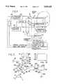
- FIG. 1represents a block diagram of a system for the internal heat treatment of a specific body according to the invention
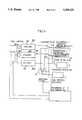
- FIG. 2represents a block diagram of an essential constituent element of the system which is the subject of the present invention as represented in FIG. 1, in this instance of a dual-temperature-reference radiometer;
- FIG. 3arepresents an advantageous non-limiting embodiment of a dual-temperature-reference radiometer capable of being used for implementing a system for the internal heat treatment of a specific body according to the invention as presented in FIG. 1;
- FIGS. 3b, 3c and 3drelate to the use of the system for the internal heat treatment of specific bodies, which is the subject of the invention, and in particular to a calibration process for this system, under best calibration precision conditions, prior to and/or in the course of a treatment session;
- FIG. 3erepresents an embodiment of the dual-temperature-reference radiometer as represented in FIG. 3a;
- FIG. 4represents an advantageous, non-limiting embodiment of a system for the internal heat treatment of a specific body, more particularly adapted to the treatment of ademona of the prostate;
- FIGS. 5a, 5b and 5crelate to various embodiments of microwave energy applicators, also capable of playing the role of temperature sensor, in accordance with an essential characteristic of the subject of the invention
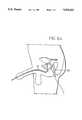
- FIG. 6arelates to the use of the system for the internal heat treatment of specific bodies according to the invention, in the case of the treatment of living tissues, with a view to reducing an adenoma of the prostate.
- FIGS. 6b and 6crelate to the use of the system for the internal heat treatment of specific bodies according to the invention in a general case, and especially in the case of FIG. 6a.
- FIG. 1A more detailed description of a system for the internal heat treatment of specific bodies by application of microwave energy to an area to be treated, in accordance with the subject of the present invention, will be given in connection with FIG. 1.
- the carrier wave of the microwave energy of 2 consecutive channels, the channels 20 and 21 in FIG. 1,exhibit a phase shift of defined value.
- the system which is the subject of the present inventioncomprises at least one microwave applicator 30, 31, associated with at least 1 channel.
- the applicator 30is, for example, associated with the channel 20, while the applicator 31 is associated with the channel 21.
- Each applicatorthus makes it possible to ensure application of the microwave energy delivered by the corresponding channel at separate points in the vicinity of the area Z to be treated.
- the lattercomprises a dual-temperature-reference radiometer 4.
- the radiometer 4may be connected selectively to one or the other of the microwave sensors 30, 31, each applicator then playing the role of temperature sensor and thus makes it possible to measure the absolute temperature of the corresponding separate point in the vicinity of the area Z to be treated.
- FIG. 1shows the selective interconnection of the dual-temperature-reference radiometer 4 to one and/or to the other applicators 30, 31, by means of a first multichannel microwave changeover switch 5 and of a second multichannel microwave changeover switch 6.
- the use of two multichannel microwave changeover switches 5 and 6, as represented in FIG. 1,does not in any way prejudice the use of a single multichannel microwave changeover switch to provide a similar function.
- the system which is the subject of the present inventioncomprises a console for calculation and display of the microwave powers radiated and of the instantaneous temperatures of the separate points of the area Z to be treated.
- the calculation and display console 7comprises, for example, a microcomputer equipped with its peripheral resources, this microcomputer being interconnected, on the one hand, to the microwave energy generator 1 so as to control the emission of the carrier wave of the microwave signal tasked with delivering the thermal treatment energy, to one or more phase shifting circuits such as the circuit 210 represented on the transmission channel 21, the phase shift being controlled by means of the microcomputer of the calculation and display console 7 as a function of the applications in question, as will be described later in the description.
- the calculation and display console 7makes it possible to control, by means of an interconnection, the microwave changeover switches 5 and 6 in such a way as to provide for the changeover switching of the applicators 30 and 31 for example, either in connection with the dual-temperature-reference radiometer 4, or in connection with the respective channels 20 or 21.
- One of the components making it possible to obtain the greatest precision relative to the temperature reached by the area Z to be treatedconsists, in accordance with one of the subjects of the present invention, in the use of a dual-temperature-reference radiometer 4.
- the dual-reference radiometer 4may comprise a first microwave changeover switch 43 comprising two input channels marked 43a, 43b. These input channels are connected, one, 43a, to the output of an applicator by means of a multichannel microwave changeover switch, marked 43, and the other, 43b, to a microwave short-circuit, marked 42.
- An output 43c of the microwave changeover switch 43may be connected to one or the other of the two abovementioned inputs.
- the dual-temperature-reference radiometer 4further comprises a circulator 411 comprising 3 channels, 411a, 41lb, 411c.
- the first channel 411ais connected to the output of the first microwave changeover switch 43 and the second channel 411b is connected to the input of a microwave electronic treatment assembly marked 414, 415, 416, 417.
- the third channel 411c of the circulator 411constitutes a reference input, that is to say an input receiving the signal delivered by one of the temperature references as will be described later in the description.
- the dual-reference radiometer 4also comprises at least 2 internal temperature reference sources, 47, 48, and a second microwave changeover switch, 49.
- the second microwave changeover switch 49comprises at least two input channels, 49a and 49b, each connected to the output of one of the reference sources, 47, 48 respectively.
- the second microwave changeover switch 49comprises an output 49c connected to the third reference input of the circulator 411c.
- the dual-temperature-reference radiometercomprises a synchronization control circuit, 417, which acts as much on the first microwave changeover switch 43 as on the second, 49, in order to obtain at least four different successive output signals, each of the abovementioned signals corresponding to each of the possibilities for connection of the two respective microwave changeover switches 43 and 49.
- the first microwave changeover switch 43comprises 2 input channels
- the second microwave changeover switch 49comprises at least 2 input channels.
- the output, 411b, of the circulator 411is linked to a microwave amplifier, 414, and the output of the microwave amplifier 414 is itself linked to a microwave detector, 415, with one input, marked 415b.
- the output, 415a, of the microwave detector 415is linked to a sampling circuit 416, which delivers sampled values of the signals delivered by the microwave detector 415 by means of an output, 418, to the calculation and display console 7.
- the calculation and display console 7allows, under the control of the control and synchronization circuit, 417, in particular, calculating, on the basis of the sampled values of the 4 successive abovementioned signals, the temperature in the region of the applicator in question, independently of the reflection coefficient of the applicator with respect to the area Z to be treated and of the losses in the microwave changeover switches and the interconnection cables.
- the value of the absolute temperature T of the region Z to be treatedmay be determined, on the basis of reference temperatures T1 and T2 which are known from the resistive elements connected to the second changeover switch 49, and represented by the references 47 and 48 in FIG. 2, and of the voltages available at the output of the sampler 416, this independently of the reflection coefficient r and of the width P of the pass band of the device.
- the temperature measurement device constituted by the dual-temperature-reference radiometer 4is composed mainly of the microwave changeover switch 43 represented in FIG. 2 with two channels, this changeover switch possibly being produced by a changeover switch of MICROWAVE model F 9120 or F 9220 general type tuned to the working frequency linking the input 411a of the circulator, either to the antenna of the applicator 30 or 31, or to the short-circuit 42 previously described in the description.
- the link cables between the microwave changeover switch 43 and the corresponding applicator, the short-circuit 42 and this same microwave changeover switchmust be of very low loss and of equal length, marked B1 on FIG. 3a, so as to exhibit the same coefficients of transmission of the corresponding signals.
- the circulator 411is a wide band circulator, the frequency band of the latter being at least equal to 1 GHz around the central frequency of the system, which can be taken to be equal, for the dual-reference radiometer 4, to 1.2 or 3 or 9 GHz.
- the abovementioned circulatormay be, for example, a 3-channel circulator of NARDA COS 2652 type or the like.
- microwave changeover switch 49makes it possible to switch over the 2 noise sources at reference temperature 47, 48, which supply the reference temperatures TRj, with j taking the values 1 or 2.
- a combination of the changeover positions of the microwave changeover switches 43 and 49, as described by the table given below,makes it possible to obtain the various signals S1, S2 and S3, S4 at the output of the sampling unit 416.
- Kdesignates the Boltzmann's constant
- Pdesignates the value of the pass band of the dual-reference radiometer 4
- rdesignates the value of the coefficient of reflection of the applicator 30 or 31 in question.
- the value of the absolute temperature T of the region Z to be treatedis thus calculable on the basis of the reference temperatures TR1 and TR2, and this can be done completely independently in relation to the coefficient of reflection r and to the width P of the pass band of the dual-reference radiometer.
- the dual-reference radiometer 4comprises a sampling module, 420, with three outputs.
- a first output, 421, of the sampling module 420is linked to an electrical short-circuit in the microwave frequency band of the radiometer 4
- a second output, 422, of the sampling moduleis linked to a first calibrated resistor of defined value in the frequency band of the radiometer, this resistor being taken at first to a temperature T1 of defined value.
- the third output 423 of the sampling module 420is linked to a second calibrated resistor of the same defined value in the frequency band of the radiometer 4, this second resistor being taken in operation to a defined temperature T2.
- the microwave changeover switch 43 of the dual-reference radiometermay then be replaced by a multichannel microwave changeover switch marked 643, the reference 643 in fact designating a combination of the two-channel microwave changeover switch 43 of FIG. 2 and of the multichannel microwave changeover switch 6 of FIG. 1, for example.
- the multichannel microwave changeover switch 643makes it possible to selectively link, to the input forming measurement input of the dual-reference radiometer 4, either one of the microwave applicators 30 or 31, or one of the outputs of the sampling module.
- the multichannel microwave changeover switch 643is a changeover switch with 6 inputs and one output, the 6 inputs being marked 643a, b, d, e, f, g, and the output being marked 643c by analogy with the microwave changeover switch 643 of FIG. 2.
- the inputs 643d, e, fare linked respectively to the first 421, second 422, and third 423 output of the three-output sampling module 420.
- the inputs 643g, a and bare linked respectively to the terminals 5a, 5d, of the multichannel changeover switch 5 as represented in FIG. 1 and to the short-circuit 42.
- the measurement input of the dual-reference radiometer 4is produced either by the terminal 643g, or by the terminal 643a of the multichannel changeover switch 643.
- interconnection cables between the multichannel changeover switch 643, the previously described inputs of the latter and their various linking pointsmay advantageously consist of cables of equal length marked B1 as shown in FIG. 3a.
- the length of the cablesis thus chosen so as to strike a balance for the device as far as the losses introduced by the abovementioned connection cables are concerned.
- the calibrationcan be carried out on the basis of one of the applicators 30, 31 in a similar way.
- the measurement input of the dual-reference radiometer 4will then be considered as the terminal 643c of the multichannel microwave changeover switch 643, which can be interconnected to one of the input terminals previously described in the description of the multichannel changeover switch 643.
- the calibration processin accordance with a subject of the present invention, then consists advantageously, as illustrated in connection with FIG. 3b, firstly in connecting the measurement input of the dual-reference radiometer to the first output 421 of the calibration module 420, the measurement input of the dual-reference radiometer 4 then being short-circuited.
- the second multichannel changeover switch 49 of the dual-reference radiometer 4is then connected to the first, TR1, then to the second, TR2, temperature reference as illustrated in FIG. 3b.
- the corresponding values Vo1 and Vo2 of the signal delivered by the sampling circuit 416are then measured and stored in memory.
- the calibration processconsists, secondly, as shown in FIG. 3c in connecting the measurement input of the dual-reference radiometer 4 to the second output 422 of the sampling module 420.
- the abovementioned measurement inputis then connected to the resistor of defined value taken to the temperature T1 of defined value.
- the second multichannel changeover switch 49is then connected to the first TR1, then to the second TR2 temperature reference.
- the corresponding values V11 and V12 of the signal delivered by the sampling circuit 416are then measured and stored in memory.
- calibration processconsists in connecting the measurement input of the dual-reference radiometer to the third output 423 of the sampling module 420.
- the abovementioned measurement inputis then connected to the resistor of defined value taken to the temperature T2 of defined value.
- the second multichannel changeover switch 49 of the dual-reference radiometer 4is then connected to the first TR1, then to the second TR2, temperature reference.
- the corresponding values V21 and V22 of the signal delivered by the sampling circuit 416are then measured and stored in memory.
- Vijdesignates each abovementioned memory-stored value
- Kdesignates the product of the gain G of the chain and Boltzmann's constant KB
- ⁇ Fdesignates the pass band of the dual-reference radiometer
- TRJdesignates either the first TR1, or the second TR2 reference temperature, for j taking the values 1, 2 respectively,
- K1 and K2designate the loss coefficients of the first microwave changeover switch 643 for the channels 1 and 2,
- linear equations having the abovementioned memory-stored values Vij and the parameters of the abovementioned devicemay then be resolved digitally by means of the microcomputer constituting the calculation and display console 7 for determining the abovementioned parameters.
- the previously described calibration processmay be implemented more particularly in the context of a calibration carried out in the laboratory in the manner described below when the two temperatures T1 and T2 to which the resistors of the calibration module 420 are taken are adjustable.
- the calibration processmay consist, advantageously:
- the steps previously described secondly and thirdly in the previous calibration processare carried out in relation to the reference temperatures TR1, TR2 successively, the adjustable temperature T1, T2, that is to say one of the two, being adjusted progressively so as to obtain a nil value for the corresponding values V11, V12 or V21, V22, delivered by the sampling circuit 416, for corresponding values known as zero temperatures, and marked respectively TZ1, TZ2, of the adjustable temperatures T1 or T2.
- Each zero temperaturesatisfies a relation of the type:
- TZj(TRj.K1 2 -Tcab.K2(1-a)+Voj)/(a.K2.K. ⁇ F).
- jneedless to say designates the index which may take the value 1 or 2 relative to the temperature reference actually used.
- Kdesignates the product of the gain of the chain with the Boltzmann's constant KB.
- the existence of the short-circuit 42, which is linked to the terminal 643b of the multichannel changeover switch 643, and of the short-circuit linked to the output 421 of the calibration module 420implies the use of identical connecting cables, so as to bring about good physical balancing of the whole of the system.
- This balancingmay be checked by comparison of sampled signals or voltages delivered by the sampling module 416, a value which is identical or substantially identical, to within measurement errors, of these signals delivered respectively by the sampled detection module 416 when switching to one or the other of the short-circuits indicating satisfactory balancing of the whole of the device.
- one of the short-circuitsmay be removed, and, in this case, the multichannel microwave changeover switch 643 comprises one less input terminal, the short-circuit of the calibration module 420 and the first output 421 of the latter being, for example, removed.
- the calibration module 420is then a two-output, 422 and 423, calibration module.
- Such a modification of the calibration modulemakes it possible in fact to produce a calibration module equivalent to that previously described in the description.
- the system which is the subject of the present inventioncomprises, advantageously, a first, 20, a second, 21, and a third, 22, transmission channels connected in parallel at the output of the microwave energy generator 1.
- a first, 30, and a second, 31, microwave applicator (sic)are provided, the first microwave applicator, 30, a rectal applicator, being linked, on the one hand to the output of the first channel 20, and, on the other hand, selectively to the output of the second channel, 21, or to the measurement input of the dual-reference radiometer 4 by means of a first and of a second multichannel microwave changeover switches, which are marked 5 and 6 in FIG. 4.
- the second applicator, 31, a urethral applicatoris also selectively linked to the output of the third channel, 22, or, on the other hand, to the measurement input of the dual-reference radiometer by means of the first multichannel changeover switch 5 and of the second multichannel changeover switch 6.
- first and second applicators 30, 31,are thermostatically controlled by means of a thermostatic control unit 8, which delivers a thermostatic control fluid to each of the abovementioned applicators.
- the thermostatic control unitwill not be described in detail, as it corresponds to a constituent element known to the person skilled in the art.
- the second and third channels, 20, 21each comprise a programmable phase shifter circuit, 210, 211, making it possible to phase shift the carrier wave of the microwave energy transmitted to the corresponding applicators, 30, 31.
- each channel 20, 21, 22,comprises a corresponding amplifier, 201, 211, 221, for the microwave energy, this amplifier being capable of playing the role of modulator so as to modulate the carrier wave according to a series of pulses of defined mark-space ratio, the mark-space ratio thus making it possible to determine the microwave energy actually applied in the region of each applicator.
- the previously mentioned microwave modulator amplifier deviceswill not be described in detail, as it (sic) can be represented by any modulator amplifier device normally available on the market for providing amplification and modulation of microwave energy, whose frequency f0 is substantially equal to 915 MHz.
- the urethral applicatorcomprises, in a probe of the Foley probe type, a wire antenna 311 connected to the corresponding changeover switch via a microwave connector, 3110a, and a coaxial cable, 3110b.
- the urethral applicatoralso comprises a water inlet tube, 312, and a water outlet tube, 313, in the probe, the water being delivered by the thermostatic control unit 8 and thus making it possible to provide a flow of water playing the role of thermostatic control fluid.
- the wire antenna constituted by the microwave cable 311comprises a stop, 3113, arranged at a suitable distance from the end of the abovementioned wire antenna, this stop being intended to adjust the effective length of the wire antenna in the Foley type probe.
- the stop 3113may be produced from a plastic material, for example, bonded to the microwave cable 3110b.
- the wire antenna 311is formed by the coaxial cable exhibiting successively at its end in the direction of forward propagation of the microwave energy, a part, 3111, of length h over which the shielding of the coaxial cable has been removed, the central core of the coaxial cable being covered over this part by the dielectric material of the cable.
- a part, 3112, of length h'is formed by the central core of the completely bared coaxial cable. The lengths h and h' are determined on the basis of the frequency f0 of the carrier wave of the microwave energy and of the dimensions of the area to be heated.
- the parts of length h and h'are covered over by a cap, 3114, made of dielectric material.
- the capexhibits an oblong shape so as to provide impedance matching of the wire antenna to the surrounding tissue.
- FIG. 4A detailed description of an operating mode, i.e. of a utilisation mode of the system which is the subject of the present invention as represented in FIG. 4, more particularly in the case of treatment of an adenoma of the prostate, will be given in connection with FIGS. 6a to c.
- the treatment process propercomprises, after implantation of the rectal and urethral applicators 30, 31, as represented in FIG. 6a in the corresponding appropriate physiological cavity or cavities, in particular steps consisting in emitting, to the abovementioned applicator or applicators 30, 31 a defined microwave energy level and modulating the relative phase of the carrier wave of the microwave energy transmitted by two consecutive channels according to a defined modulation program in order to modulate the energy level transferred to the region of the area to be treated Z.
- the area Z to be treatedencompasses the prostate subjected to the treatment, this area Z being situated between the two applicators after implantation of the latter.
- FIG. 6cis represented, by way of nonlimiting example, a change law for the temperature rise of the area Z to be treated towards a constant temperature marked Tass, which can be maintained by periodic emission by one and/or by the other applicator 30, 31.
- the servo controlled temperature Tassas well as the slope p, or the law of convergence towards this servo controlled temperature, are defined by the practitioner on the basis of the application in question.
- the slope p or the law of convergence towards the servo controlled temperaturemay be chosen in such a way as to correspond to an increasing monotonous function of the temperature as a function of time by temperature increment ⁇ T lying between 0.8° C. to 1.2° C. per minute.
- the radiated powerwhich corresponds to a radiated maximum radiated (sic) electrical power of 50 watts may then be adjusted so as to satisfy, for the power increments applied by each successive radiation, the relation:
- ⁇ PM. ⁇ T+N. ⁇ T theoretical/ ⁇ T achieved.
- ⁇ Prepresents the power increment delivered by one and/or the other of the applicators 31 or 30,
- Mrepresents a coefficient of proportionality depending on the area, and finally on the organ to be treated, and on the applicators used,
- ⁇ Trepresents the temperature increase with respect to the previous measurement by means of the dual-reference radiometer
- Nrepresents a coefficient of proportionality depending also on the organ and on the applicators used as well as on the temperature increase law chosen by the practitioner,
- ⁇ T theoreticalis a value stored in memory within the microcomputer constituting the calculation and display console 7, these memory-stored values corresponding to the application in question and constituting, for this application, a data base available to the practitioner, and,
- ⁇ T achievedbeing the temperature increase measured by the dual-reference radiometer between two temperature measurements separated by the application of a given quantity of microwave energy.
- the hottest point of the area Z treatedmoves either in front of the urethra or behind the rectum, having regard to the thickness of the prostate.
- the various phases and the ratio of the microwave powers radiated by each of the channelsin order to obtain maximum thermal effectiveness.
- the three channelsdeliver an in-phase microwave power, the powers delivered by each of the channels being identical, the hottest area is situated substantially midway between the urethra and the rectal wall.
- treatmentmay consist in varying, as a function of time, the phase of the carrier wave delivered by each of the channels and in particular by two consecutive channels, either continuously by phase which is variable between 0° and 180°, or with fixed phase shift values, for example.
- a treatment modemay consist for:
- sequencing timeis a function of the geometry and of the volume of the organ to be treated and hence of the area Z subjected to the hyperthermia.
- This sequencingin order to produce an optimum thermal effect, according to a theoretical study carried out, should lie between 3 and 9 seconds.
- the multichannel microwave changeover switchesmake it possible to switchover the various applicators, the latter operating either as microwave energy applicators, or as temperature sensors or detectors.
- the various applicatorsoperating either as microwave energy applicators, or as temperature sensors or detectors.
Landscapes
- Health & Medical Sciences (AREA)
- Life Sciences & Earth Sciences (AREA)
- Engineering & Computer Science (AREA)
- Biomedical Technology (AREA)
- General Health & Medical Sciences (AREA)
- Veterinary Medicine (AREA)
- Nuclear Medicine, Radiotherapy & Molecular Imaging (AREA)
- Animal Behavior & Ethology (AREA)
- Surgery (AREA)
- Public Health (AREA)
- Pathology (AREA)
- Physics & Mathematics (AREA)
- Electromagnetism (AREA)
- Otolaryngology (AREA)
- Radiology & Medical Imaging (AREA)
- Heart & Thoracic Surgery (AREA)
- Medical Informatics (AREA)
- Molecular Biology (AREA)
- Radiation Pyrometers (AREA)
Abstract
Description
______________________________________ Change- Changeover Switch Position over 4943 49a 49b SwitchPosition 43a S2 = K.P.[r.TR1 + S4 = K.P.[r.TR2 + (1 - r)T] (1 - r)T] 43b S1 = K.P.TR1 S3 = K.P.TR2 ______________________________________
Va≃S1-S2
Vb≃S3-S4
______________________________________ t = 0urethral applicator 31 phase = 0°rectal applicator channel 21 phase = 0°rectal applicator channel 20 phase = 120° t = 4 seconds cyclic permutation urethral phase = 120°, the other phases being taken to be equal to 0°. ______________________________________
Claims (14)
Applications Claiming Priority (3)
| Application Number | Priority Date | Filing Date | Title |
|---|---|---|---|
| FR9109521AFR2679455B1 (en) | 1991-07-26 | 1991-07-26 | SYSTEM FOR THE INTERNAL HEAT TREATMENT OF A CERTAIN BODY AND ITS USE. |
| FR9109521 | 1991-07-26 | ||
| PCT/FR1992/000729WO1993002747A1 (en) | 1991-07-26 | 1992-07-23 | System for internally treating a body by thermic means and use thereof |
Publications (1)
| Publication Number | Publication Date |
|---|---|
| US5354325Atrue US5354325A (en) | 1994-10-11 |
Family
ID=9415604
Family Applications (1)
| Application Number | Title | Priority Date | Filing Date |
|---|---|---|---|
| US08/030,247Expired - LifetimeUS5354325A (en) | 1991-07-26 | 1992-07-23 | System for internal heat treatment of a specific body and its use |
Country Status (6)
| Country | Link |
|---|---|
| US (1) | US5354325A (en) |
| EP (1) | EP0552341B1 (en) |
| JP (1) | JP3348216B2 (en) |
| DE (1) | DE69227888T2 (en) |
| FR (1) | FR2679455B1 (en) |
| WO (1) | WO1993002747A1 (en) |
Cited By (58)
| Publication number | Priority date | Publication date | Assignee | Title |
|---|---|---|---|---|
| WO1998027644A1 (en)* | 1996-12-03 | 1998-06-25 | Raytheon Company | Microwave active solid state cold/warm noise source |
| WO1999058194A1 (en)* | 1998-05-08 | 1999-11-18 | Thermatrx, Inc. | Therapeutic prostatic thermotherapy |
| US6064914A (en)* | 1998-04-01 | 2000-05-16 | Trachtenberg; John R. | Thermotherapy method |
| US6136020A (en)* | 1998-06-26 | 2000-10-24 | Faour; Ali M. | Treatment for prostatitis and apparatus therefor |
| EP1068879A2 (en)* | 1999-07-13 | 2001-01-17 | Terumo Kabushiki Kaisha | Apparatus for thermotherapy |
| WO2001012261A1 (en)* | 1999-08-19 | 2001-02-22 | Kai Technologies, Inc. | Microwave devices for medical hyperthermia, thermotherapy and diagnosis |
| US6217210B1 (en) | 1996-12-03 | 2001-04-17 | Raytheon Company | Variable microwave cold/warm noise source |
| FR2820327A1 (en)* | 2001-02-06 | 2002-08-09 | Mohamed Ayari | PROCESS FOR OBTAINING A SET OF ELECTROMAGNETIC FIELDS WITH DIAGNOSTIC, PREVENTIVE, THERAPEUTIC AND BIOTECHNOLOGICAL VIEWS |
| US6477426B1 (en)* | 2000-06-20 | 2002-11-05 | Celsion Corporation | System and method for heating the prostate gland to treat and prevent the growth and spread of prostate tumors |
| US6640138B1 (en) | 2000-08-04 | 2003-10-28 | Thermatrx, Inc. | Apparatus and method for heat treatment of tissue |
| US6834991B2 (en) | 2002-09-23 | 2004-12-28 | Raytheon Company | Radiometer with programmable noise source calibration |
| US20050190815A1 (en)* | 2003-10-16 | 2005-09-01 | Samsung Electronics Co., Ltd. | Radio-thermometer system and method for measuring electromagnetic energy radiated from an interior of a human body using the same |
| US7645142B2 (en) | 2007-09-05 | 2010-01-12 | Vivant Medical, Inc. | Electrical receptacle assembly |
| US20100079215A1 (en)* | 2008-09-30 | 2010-04-01 | Brannan Joseph D | System, apparatus and method for dissipating standing wave in a microwave delivery system |
| US20100082025A1 (en)* | 2008-09-30 | 2010-04-01 | Brannan Joseph D | Microwave ablation generator control system |
| US20100082022A1 (en)* | 2008-09-30 | 2010-04-01 | Haley Kaylen J | Delivered energy generator for microwave ablation |
| US20100082083A1 (en)* | 2008-09-30 | 2010-04-01 | Brannan Joseph D | Microwave system tuner |
| US20100082024A1 (en)* | 2008-09-30 | 2010-04-01 | Brannan Joseph D | Intermittent microwave energy delivery system |
| US20100082084A1 (en)* | 2008-09-30 | 2010-04-01 | Brannan Joseph D | Microwave system calibration apparatus and method of use |
| US20100082023A1 (en)* | 2008-09-30 | 2010-04-01 | Brannan Joseph D | Microwave system calibration apparatus, system and method of use |
| US20100087797A1 (en)* | 2008-10-07 | 2010-04-08 | Christcot Medical Company | Method and apparatus for inserting a rectal suppository |
| US20100087808A1 (en)* | 2008-10-03 | 2010-04-08 | Vivant Medical, Inc. | Combined Frequency Microwave Ablation System, Devices and Methods of Use |
| US20100185191A1 (en)* | 2009-01-20 | 2010-07-22 | Meridian Medical Systems, Llc | Method and apparatus for aligning an ablation catheter and a temperature probe during an ablation procedure |
| WO2010090701A1 (en)* | 2009-01-20 | 2010-08-12 | Advanced Cardiac Therapeutics Inc. | Method and apparatus for minimizing thermal trauma to an organ during tissue ablation of a different organ |
| US8152800B2 (en) | 2007-07-30 | 2012-04-10 | Vivant Medical, Inc. | Electrosurgical systems and printed circuit boards for use therewith |
| US8231616B2 (en) | 2006-09-28 | 2012-07-31 | Covidien Ag | Transformer for RF voltage sensing |
| US8241278B2 (en) | 2005-12-12 | 2012-08-14 | Covidien Ag | Laparoscopic apparatus for performing electrosurgical procedures |
| US8267929B2 (en) | 2003-05-01 | 2012-09-18 | Covidien Ag | Method and system for programming and controlling an electrosurgical generator system |
| US8267928B2 (en) | 2006-01-24 | 2012-09-18 | Covidien Ag | System and method for closed loop monitoring of monopolar electrosurgical apparatus |
| US8486061B2 (en) | 2009-01-12 | 2013-07-16 | Covidien Lp | Imaginary impedance process monitoring and intelligent shut-off |
| US8485993B2 (en) | 2003-10-30 | 2013-07-16 | Covidien Ag | Switched resonant ultrasonic power amplifier system |
| US8523855B2 (en) | 2002-12-10 | 2013-09-03 | Covidien Ag | Circuit for controlling arc energy from an electrosurgical generator |
| US8647340B2 (en) | 2003-10-23 | 2014-02-11 | Covidien Ag | Thermocouple measurement system |
| US8740893B2 (en) | 2010-06-30 | 2014-06-03 | Covidien Lp | Adjustable tuning of a dielectrically loaded loop antenna |
| US8747398B2 (en) | 2007-09-13 | 2014-06-10 | Covidien Lp | Frequency tuning in a microwave electrosurgical system |
| US8926605B2 (en) | 2012-02-07 | 2015-01-06 | Advanced Cardiac Therapeutics, Inc. | Systems and methods for radiometrically measuring temperature during tissue ablation |
| US8954161B2 (en) | 2012-06-01 | 2015-02-10 | Advanced Cardiac Therapeutics, Inc. | Systems and methods for radiometrically measuring temperature and detecting tissue contact prior to and during tissue ablation |
| US8961506B2 (en) | 2012-03-12 | 2015-02-24 | Advanced Cardiac Therapeutics, Inc. | Methods of automatically regulating operation of ablation members based on determined temperatures |
| US9095359B2 (en) | 2009-09-18 | 2015-08-04 | Covidien Lp | Tissue ablation system with energy distribution |
| US9113900B2 (en) | 1998-10-23 | 2015-08-25 | Covidien Ag | Method and system for controlling output of RF medical generator |
| US9277961B2 (en) | 2009-06-12 | 2016-03-08 | Advanced Cardiac Therapeutics, Inc. | Systems and methods of radiometrically determining a hot-spot temperature of tissue being treated |
| WO2016081598A1 (en)* | 2014-11-19 | 2016-05-26 | Advanced Cardiac Therapeutics, Inc. | Systems and methods for facilitating consistent radiometric tissue contact detection independent of orientation |
| US9510905B2 (en) | 2014-11-19 | 2016-12-06 | Advanced Cardiac Therapeutics, Inc. | Systems and methods for high-resolution mapping of tissue |
| US9517103B2 (en) | 2014-11-19 | 2016-12-13 | Advanced Cardiac Therapeutics, Inc. | Medical instruments with multiple temperature sensors |
| US9636164B2 (en) | 2015-03-25 | 2017-05-02 | Advanced Cardiac Therapeutics, Inc. | Contact sensing systems and methods |
| US9636165B2 (en) | 2013-07-29 | 2017-05-02 | Covidien Lp | Systems and methods for measuring tissue impedance through an electrosurgical cable |
| US9662481B2 (en) | 2008-10-07 | 2017-05-30 | Cristcot Llc | Method and apparatus for inserting a rectal suppository |
| US9700366B2 (en) | 2008-08-01 | 2017-07-11 | Covidien Lp | Polyphase electrosurgical system and method |
| US9861424B2 (en) | 2007-07-11 | 2018-01-09 | Covidien Lp | Measurement and control systems and methods for electrosurgical procedures |
| US9872719B2 (en) | 2013-07-24 | 2018-01-23 | Covidien Lp | Systems and methods for generating electrosurgical energy using a multistage power converter |
| US9993178B2 (en) | 2016-03-15 | 2018-06-12 | Epix Therapeutics, Inc. | Methods of determining catheter orientation |
| US10149967B2 (en) | 2012-10-19 | 2018-12-11 | Cristcot Llc | Suppository insertion device, suppository, and method of manufacturing a suppository |
| US10166062B2 (en) | 2014-11-19 | 2019-01-01 | Epix Therapeutics, Inc. | High-resolution mapping of tissue with pacing |
| US10828100B2 (en)* | 2009-08-25 | 2020-11-10 | Covidien Lp | Microwave ablation with tissue temperature monitoring |
| US10888373B2 (en) | 2017-04-27 | 2021-01-12 | Epix Therapeutics, Inc. | Contact assessment between an ablation catheter and tissue |
| US11103308B2 (en) | 2017-12-11 | 2021-08-31 | Covidien Lp | Reusable transmission network for dividing energy and monitoring signals between surgical devices |
| US11298515B2 (en) | 2016-05-12 | 2022-04-12 | Cristcot Llc | Single-use suppository insertion device and method |
| US12226143B2 (en) | 2020-06-22 | 2025-02-18 | Covidien Lp | Universal surgical footswitch toggling |
Families Citing this family (7)
| Publication number | Priority date | Publication date | Assignee | Title |
|---|---|---|---|---|
| FR2708736B1 (en)* | 1993-07-29 | 1995-10-20 | Sadis Bruker Spectrospin | Method for calibrating and calibrating a radiometer for temperature measurement. |
| FR2720948B1 (en)* | 1994-06-10 | 1996-09-27 | Sadis Bruker Spectrospin | Apparatus for in situ treatment by hyperthermia or thermotherapy. |
| FR2723784B1 (en)* | 1994-08-19 | 1997-01-17 | Sadis Bruker Spectrospin | RADIOMETER FOR DETERMINING A TEMPERATURE OF A BODY BY MEASURING THE THERMAL NOISE EMITTED AND MEASURING METHOD USING THE SAME |
| FR2880115B1 (en)* | 2004-12-23 | 2007-03-16 | Air Liquide | METHOD AND INSTALLATION FOR MEASURING AND CONTROLLING BODY TEMPERATURE BY MICROWAVE RADIOMETRY IN EXTREME ENVIRONMENT TAKING INTO ACCOUNT THE CHARACTERISTICS OF THE BONDING MEMBER CONNECTING THE SENSOR TO THE RADIOMETER |
| FR2880122A1 (en)* | 2004-12-23 | 2006-06-30 | Air Liquide | METHOD AND INSTALLATION FOR DETECTING THE PRESENCE OF A BODY |
| JP2011502671A (en)* | 2007-11-14 | 2011-01-27 | ルネウェーブ メディカル システムズ エスエイ. | Effect of high-frequency electromagnetic field on cell growth and method for laparoscopic treatment |
| GB201220353D0 (en)* | 2012-11-12 | 2012-12-26 | Scentbands Ltd | Flexible articles incorporating a liquid additive and methods for the manufacture of such articles |
Citations (10)
| Publication number | Priority date | Publication date | Assignee | Title |
|---|---|---|---|---|
| US4632128A (en)* | 1985-06-17 | 1986-12-30 | Rca Corporation | Antenna apparatus for scanning hyperthermia |
| SU1345142A1 (en)* | 1986-03-06 | 1987-10-15 | Предприятие П/Я В-2539 | Noise heat generator |
| WO1988003823A1 (en)* | 1986-11-28 | 1988-06-02 | Bsd Medical Corporation | Hyperthermia apparatus |
| US4785829A (en)* | 1985-12-10 | 1988-11-22 | C.G.R Mev | Apparatus for hyperthermic treatment |
| SU1567203A1 (en)* | 1988-07-11 | 1990-05-30 | Институт электроники АН БССР | Device for physiotherapy of prostate disease |
| EP0370890A1 (en)* | 1988-11-21 | 1990-05-30 | Technomed Medical Systems | Apparatus for the surgical treatment of tissues by hyperthermia, preferably the prostate, equipped with heat protection means preferably comprising means forming radioreflecting screen |
| FR2650390A1 (en)* | 1989-07-27 | 1991-02-01 | Inst Nat Sante Rech Med | Method for measuring temperatures by microwave radiometry, with automatic calibration of the measurement, and device for implementing this method |
| US5007437A (en)* | 1989-06-16 | 1991-04-16 | Mmtc, Inc. | Catheters for treating prostate disease |
| US5033478A (en)* | 1984-07-24 | 1991-07-23 | Tokyo Keiki Co., Ltd. | Heating apparatus for hyperthermia |
| EP0485323A1 (en)* | 1990-11-09 | 1992-05-13 | Biodan Medical Systems Ltd | Hyperthermia apparatus |
- 1991
- 1991-07-26FRFR9109521Apatent/FR2679455B1/ennot_activeExpired - Lifetime
- 1992
- 1992-07-23DEDE69227888Tpatent/DE69227888T2/ennot_activeExpired - Lifetime
- 1992-07-23EPEP92916843Apatent/EP0552341B1/ennot_activeExpired - Lifetime
- 1992-07-23JPJP50331593Apatent/JP3348216B2/ennot_activeExpired - Lifetime
- 1992-07-23WOPCT/FR1992/000729patent/WO1993002747A1/enactiveIP Right Grant
- 1992-07-23USUS08/030,247patent/US5354325A/ennot_activeExpired - Lifetime
Patent Citations (11)
| Publication number | Priority date | Publication date | Assignee | Title |
|---|---|---|---|---|
| US4798215A (en)* | 1984-03-15 | 1989-01-17 | Bsd Medical Corporation | Hyperthermia apparatus |
| US5033478A (en)* | 1984-07-24 | 1991-07-23 | Tokyo Keiki Co., Ltd. | Heating apparatus for hyperthermia |
| US4632128A (en)* | 1985-06-17 | 1986-12-30 | Rca Corporation | Antenna apparatus for scanning hyperthermia |
| US4785829A (en)* | 1985-12-10 | 1988-11-22 | C.G.R Mev | Apparatus for hyperthermic treatment |
| SU1345142A1 (en)* | 1986-03-06 | 1987-10-15 | Предприятие П/Я В-2539 | Noise heat generator |
| WO1988003823A1 (en)* | 1986-11-28 | 1988-06-02 | Bsd Medical Corporation | Hyperthermia apparatus |
| SU1567203A1 (en)* | 1988-07-11 | 1990-05-30 | Институт электроники АН БССР | Device for physiotherapy of prostate disease |
| EP0370890A1 (en)* | 1988-11-21 | 1990-05-30 | Technomed Medical Systems | Apparatus for the surgical treatment of tissues by hyperthermia, preferably the prostate, equipped with heat protection means preferably comprising means forming radioreflecting screen |
| US5007437A (en)* | 1989-06-16 | 1991-04-16 | Mmtc, Inc. | Catheters for treating prostate disease |
| FR2650390A1 (en)* | 1989-07-27 | 1991-02-01 | Inst Nat Sante Rech Med | Method for measuring temperatures by microwave radiometry, with automatic calibration of the measurement, and device for implementing this method |
| EP0485323A1 (en)* | 1990-11-09 | 1992-05-13 | Biodan Medical Systems Ltd | Hyperthermia apparatus |
Non-Patent Citations (6)
| Title |
|---|
| Database WPIL, Week 8819, Derwent Publ. Ltd., London GB; AN 88 132135 & SU,A, 1,345,142 (Ioselson) Oct. 15, 1987 see abstract.* |
| Database WPIL, Week 8819, Derwent Publ. Ltd., London GB; AN 88-132135 & SU,A, 1,345,142 (Ioselson) Oct. 15, 1987 -see abstract. |
| Database WPIL, Week 9103, Derwent Publ. Ltd., London GB; AN 91 020869 & SU,A, 1,567,203 (Koleshko) May 30, 1990 see abstract.* |
| Database WPIL, Week 9103, Derwent Publ. Ltd., London GB; AN 91-020869 & SU,A, 1,567,203 (Koleshko) May 30, 1990 -see abstract. |
| Mendecki et al. "Microwave Applicators For Localized Hyperthermia Treatment of Cancer of the Prostate" Int. J. Radiation Oncology Biol. Phys. vol. 6, No. 11 pp. 1583-1585, Nov. 1980. |
| Mendecki et al. Microwave Applicators For Localized Hyperthermia Treatment of Cancer of the Prostate Int. J. Radiation Oncology Biol. Phys. vol. 6, No. 11 pp. 1583 1585, Nov. 1980.* |
Cited By (124)
| Publication number | Priority date | Publication date | Assignee | Title |
|---|---|---|---|---|
| US6217210B1 (en) | 1996-12-03 | 2001-04-17 | Raytheon Company | Variable microwave cold/warm noise source |
| US6137440A (en)* | 1996-12-03 | 2000-10-24 | Raytheon Company | Microwave active solid state cold/warm noise source |
| WO1998027644A1 (en)* | 1996-12-03 | 1998-06-25 | Raytheon Company | Microwave active solid state cold/warm noise source |
| US6439763B2 (en) | 1996-12-03 | 2002-08-27 | Raytheon Company | Variable microwave cold/warm noise source |
| US6064914A (en)* | 1998-04-01 | 2000-05-16 | Trachtenberg; John R. | Thermotherapy method |
| US6522931B2 (en) | 1998-05-08 | 2003-02-18 | Thermatrx, Inc. | Therapeutic prostatic thermotherapy |
| US7089064B2 (en) | 1998-05-08 | 2006-08-08 | Ams Research Corporation | Therapeutic prostatic thermotherapy |
| US7093601B2 (en) | 1998-05-08 | 2006-08-22 | Ams Research Corporation | Therapeutic prostatic thermotherapy |
| US6216703B1 (en) | 1998-05-08 | 2001-04-17 | Thermatrx, Inc. | Therapeutic prostatic thermotherapy |
| WO1999058194A1 (en)* | 1998-05-08 | 1999-11-18 | Thermatrx, Inc. | Therapeutic prostatic thermotherapy |
| US6136020A (en)* | 1998-06-26 | 2000-10-24 | Faour; Ali M. | Treatment for prostatitis and apparatus therefor |
| US9168089B2 (en) | 1998-10-23 | 2015-10-27 | Covidien Ag | Method and system for controlling output of RF medical generator |
| US9113900B2 (en) | 1998-10-23 | 2015-08-25 | Covidien Ag | Method and system for controlling output of RF medical generator |
| EP1068879A2 (en)* | 1999-07-13 | 2001-01-17 | Terumo Kabushiki Kaisha | Apparatus for thermotherapy |
| US6275738B1 (en) | 1999-08-19 | 2001-08-14 | Kai Technologies, Inc. | Microwave devices for medical hyperthermia, thermotherapy and diagnosis |
| WO2001012261A1 (en)* | 1999-08-19 | 2001-02-22 | Kai Technologies, Inc. | Microwave devices for medical hyperthermia, thermotherapy and diagnosis |
| US6477426B1 (en)* | 2000-06-20 | 2002-11-05 | Celsion Corporation | System and method for heating the prostate gland to treat and prevent the growth and spread of prostate tumors |
| US6640138B1 (en) | 2000-08-04 | 2003-10-28 | Thermatrx, Inc. | Apparatus and method for heat treatment of tissue |
| FR2820327A1 (en)* | 2001-02-06 | 2002-08-09 | Mohamed Ayari | PROCESS FOR OBTAINING A SET OF ELECTROMAGNETIC FIELDS WITH DIAGNOSTIC, PREVENTIVE, THERAPEUTIC AND BIOTECHNOLOGICAL VIEWS |
| WO2002062418A1 (en)* | 2001-02-06 | 2002-08-15 | Mohamed Ayari | Electromagnetic set for , diagnostic, preventive, therapeutic purposes |
| US6834991B2 (en) | 2002-09-23 | 2004-12-28 | Raytheon Company | Radiometer with programmable noise source calibration |
| US8523855B2 (en) | 2002-12-10 | 2013-09-03 | Covidien Ag | Circuit for controlling arc energy from an electrosurgical generator |
| US8303580B2 (en) | 2003-05-01 | 2012-11-06 | Covidien Ag | Method and system for programming and controlling an electrosurgical generator system |
| US8298223B2 (en) | 2003-05-01 | 2012-10-30 | Covidien Ag | Method and system for programming and controlling an electrosurgical generator system |
| US8267929B2 (en) | 2003-05-01 | 2012-09-18 | Covidien Ag | Method and system for programming and controlling an electrosurgical generator system |
| US20050190815A1 (en)* | 2003-10-16 | 2005-09-01 | Samsung Electronics Co., Ltd. | Radio-thermometer system and method for measuring electromagnetic energy radiated from an interior of a human body using the same |
| US7121719B2 (en)* | 2003-10-16 | 2006-10-17 | Samsung Electronics Co., Ltd. | Radio-thermometer system and method for measuring electromagnetic energy radiated from an interior of a human body using the same |
| US8647340B2 (en) | 2003-10-23 | 2014-02-11 | Covidien Ag | Thermocouple measurement system |
| US9768373B2 (en) | 2003-10-30 | 2017-09-19 | Covidien Ag | Switched resonant ultrasonic power amplifier system |
| US8966981B2 (en) | 2003-10-30 | 2015-03-03 | Covidien Ag | Switched resonant ultrasonic power amplifier system |
| US8485993B2 (en) | 2003-10-30 | 2013-07-16 | Covidien Ag | Switched resonant ultrasonic power amplifier system |
| US8241278B2 (en) | 2005-12-12 | 2012-08-14 | Covidien Ag | Laparoscopic apparatus for performing electrosurgical procedures |
| US8267928B2 (en) | 2006-01-24 | 2012-09-18 | Covidien Ag | System and method for closed loop monitoring of monopolar electrosurgical apparatus |
| US8475447B2 (en) | 2006-01-24 | 2013-07-02 | Covidien Ag | System and method for closed loop monitoring of monopolar electrosurgical apparatus |
| US8231616B2 (en) | 2006-09-28 | 2012-07-31 | Covidien Ag | Transformer for RF voltage sensing |
| US9861424B2 (en) | 2007-07-11 | 2018-01-09 | Covidien Lp | Measurement and control systems and methods for electrosurgical procedures |
| US8152800B2 (en) | 2007-07-30 | 2012-04-10 | Vivant Medical, Inc. | Electrosurgical systems and printed circuit boards for use therewith |
| US9190704B2 (en) | 2007-07-30 | 2015-11-17 | Covidien Lp | Electrosurgical systems and printed circuit boards for use therewith |
| US7645142B2 (en) | 2007-09-05 | 2010-01-12 | Vivant Medical, Inc. | Electrical receptacle assembly |
| US8747398B2 (en) | 2007-09-13 | 2014-06-10 | Covidien Lp | Frequency tuning in a microwave electrosurgical system |
| US9498285B2 (en) | 2007-09-13 | 2016-11-22 | Covidien Lp | Impedance matching in a microwave electrosurgical system |
| US9700366B2 (en) | 2008-08-01 | 2017-07-11 | Covidien Lp | Polyphase electrosurgical system and method |
| US8242782B2 (en) | 2008-09-30 | 2012-08-14 | Vivant Medical, Inc. | Microwave ablation generator control system |
| US20100082083A1 (en)* | 2008-09-30 | 2010-04-01 | Brannan Joseph D | Microwave system tuner |
| US8287527B2 (en) | 2008-09-30 | 2012-10-16 | Vivant Medical, Inc. | Microwave system calibration apparatus and method of use |
| US20100079215A1 (en)* | 2008-09-30 | 2010-04-01 | Brannan Joseph D | System, apparatus and method for dissipating standing wave in a microwave delivery system |
| US20100082025A1 (en)* | 2008-09-30 | 2010-04-01 | Brannan Joseph D | Microwave ablation generator control system |
| US8346370B2 (en)* | 2008-09-30 | 2013-01-01 | Vivant Medical, Inc. | Delivered energy generator for microwave ablation |
| US9526576B2 (en) | 2008-09-30 | 2016-12-27 | Covidien Lp | Microwave ablation generator control system |
| US8180433B2 (en) | 2008-09-30 | 2012-05-15 | Vivant Medical, Inc. | Microwave system calibration apparatus, system and method of use |
| US20100082022A1 (en)* | 2008-09-30 | 2010-04-01 | Haley Kaylen J | Delivered energy generator for microwave ablation |
| US8174267B2 (en) | 2008-09-30 | 2012-05-08 | Vivant Medical, Inc. | Intermittent microwave energy delivery system |
| US10070922B2 (en) | 2008-09-30 | 2018-09-11 | Covidien Lp | Microwave ablation generator control system |
| US8542019B2 (en) | 2008-09-30 | 2013-09-24 | Covidien Lp | Microwave ablation generator control system |
| US8248075B2 (en)* | 2008-09-30 | 2012-08-21 | Vivant Medical, Inc. | System, apparatus and method for dissipating standing wave in a microwave delivery system |
| US10743935B2 (en) | 2008-09-30 | 2020-08-18 | Covidien Lp | Microwave ablation generator control system |
| US20100082024A1 (en)* | 2008-09-30 | 2010-04-01 | Brannan Joseph D | Intermittent microwave energy delivery system |
| EP2168518A3 (en)* | 2008-09-30 | 2010-05-12 | Vivant Medical, Inc. | Microwave system calibration apparatus, system and method of use |
| US8797039B2 (en) | 2008-09-30 | 2014-08-05 | Covidien Lp | Microwave ablation generator control system |
| US20100082084A1 (en)* | 2008-09-30 | 2010-04-01 | Brannan Joseph D | Microwave system calibration apparatus and method of use |
| US20100082023A1 (en)* | 2008-09-30 | 2010-04-01 | Brannan Joseph D | Microwave system calibration apparatus, system and method of use |
| US20100087808A1 (en)* | 2008-10-03 | 2010-04-08 | Vivant Medical, Inc. | Combined Frequency Microwave Ablation System, Devices and Methods of Use |
| US10525242B2 (en) | 2008-10-07 | 2020-01-07 | Cristcot Llc | Method and apparatus for inserting a rectal suppository |
| US20100087797A1 (en)* | 2008-10-07 | 2010-04-08 | Christcot Medical Company | Method and apparatus for inserting a rectal suppository |
| US9662481B2 (en) | 2008-10-07 | 2017-05-30 | Cristcot Llc | Method and apparatus for inserting a rectal suppository |
| US8192393B2 (en) | 2008-10-07 | 2012-06-05 | Christcot Medical Company | Method and apparatus for inserting a rectal suppository |
| US8419712B2 (en) | 2008-10-07 | 2013-04-16 | Christcot Medical Company | Method and apparatus for inserting a rectal suppository |
| US8486061B2 (en) | 2009-01-12 | 2013-07-16 | Covidien Lp | Imaginary impedance process monitoring and intelligent shut-off |
| US8731684B2 (en) | 2009-01-20 | 2014-05-20 | Meridian Medical Systems, Llc | Method and apparatus for aligning an ablation catheter and a temperature probe during an ablation procedure |
| WO2010090701A1 (en)* | 2009-01-20 | 2010-08-12 | Advanced Cardiac Therapeutics Inc. | Method and apparatus for minimizing thermal trauma to an organ during tissue ablation of a different organ |
| US20100185191A1 (en)* | 2009-01-20 | 2010-07-22 | Meridian Medical Systems, Llc | Method and apparatus for aligning an ablation catheter and a temperature probe during an ablation procedure |
| US9277961B2 (en) | 2009-06-12 | 2016-03-08 | Advanced Cardiac Therapeutics, Inc. | Systems and methods of radiometrically determining a hot-spot temperature of tissue being treated |
| US12004806B2 (en) | 2009-08-25 | 2024-06-11 | Covidien Lp | Microwave ablation with tissue temperature monitoring |
| US10828100B2 (en)* | 2009-08-25 | 2020-11-10 | Covidien Lp | Microwave ablation with tissue temperature monitoring |
| US10016237B2 (en) | 2009-09-18 | 2018-07-10 | Covidien Lp | Tissue ablation system with energy distribution |
| US9375278B2 (en) | 2009-09-18 | 2016-06-28 | Covidien Lp | Tissue ablation system with energy distribution |
| US9554855B2 (en) | 2009-09-18 | 2017-01-31 | Covidien Lp | Tissue ablation system with energy distribution |
| US9095359B2 (en) | 2009-09-18 | 2015-08-04 | Covidien Lp | Tissue ablation system with energy distribution |
| US11039885B2 (en) | 2009-09-18 | 2021-06-22 | Covidien Lp | Tissue ablation system with energy distribution |
| US8740893B2 (en) | 2010-06-30 | 2014-06-03 | Covidien Lp | Adjustable tuning of a dielectrically loaded loop antenna |
| US9549778B2 (en) | 2010-06-30 | 2017-01-24 | Covidien Lp | Adjustable tuning of a dielectrically loaded loop antenna |
| US8926605B2 (en) | 2012-02-07 | 2015-01-06 | Advanced Cardiac Therapeutics, Inc. | Systems and methods for radiometrically measuring temperature during tissue ablation |
| US8932284B2 (en) | 2012-02-07 | 2015-01-13 | Advanced Cardiac Therapeutics, Inc. | Methods of determining tissue temperatures in energy delivery procedures |
| US8961506B2 (en) | 2012-03-12 | 2015-02-24 | Advanced Cardiac Therapeutics, Inc. | Methods of automatically regulating operation of ablation members based on determined temperatures |
| US9226791B2 (en) | 2012-03-12 | 2016-01-05 | Advanced Cardiac Therapeutics, Inc. | Systems for temperature-controlled ablation using radiometric feedback |
| US8954161B2 (en) | 2012-06-01 | 2015-02-10 | Advanced Cardiac Therapeutics, Inc. | Systems and methods for radiometrically measuring temperature and detecting tissue contact prior to and during tissue ablation |
| US9014814B2 (en) | 2012-06-01 | 2015-04-21 | Advanced Cardiac Therapeutics, Inc. | Methods of determining tissue contact based on radiometric signals |
| US12337130B2 (en) | 2012-10-19 | 2025-06-24 | Cristcot Llc | Suppository insertion device, suppository, and method of manufacturing a suppository |
| US11224727B2 (en) | 2012-10-19 | 2022-01-18 | Cristcot Llc | Suppository insertion device, suppository, and method of manufacturing a suppository |
| US10149967B2 (en) | 2012-10-19 | 2018-12-11 | Cristcot Llc | Suppository insertion device, suppository, and method of manufacturing a suppository |
| US9872719B2 (en) | 2013-07-24 | 2018-01-23 | Covidien Lp | Systems and methods for generating electrosurgical energy using a multistage power converter |
| US11135001B2 (en) | 2013-07-24 | 2021-10-05 | Covidien Lp | Systems and methods for generating electrosurgical energy using a multistage power converter |
| US9636165B2 (en) | 2013-07-29 | 2017-05-02 | Covidien Lp | Systems and methods for measuring tissue impedance through an electrosurgical cable |
| US9655670B2 (en) | 2013-07-29 | 2017-05-23 | Covidien Lp | Systems and methods for measuring tissue impedance through an electrosurgical cable |
| US11534227B2 (en) | 2014-11-19 | 2022-12-27 | Epix Therapeutics, Inc. | High-resolution mapping of tissue with pacing |
| US9522036B2 (en) | 2014-11-19 | 2016-12-20 | Advanced Cardiac Therapeutics, Inc. | Ablation devices, systems and methods of using a high-resolution electrode assembly |
| US10383686B2 (en) | 2014-11-19 | 2019-08-20 | Epix Therapeutics, Inc. | Ablation systems with multiple temperature sensors |
| US10413212B2 (en) | 2014-11-19 | 2019-09-17 | Epix Therapeutics, Inc. | Methods and systems for enhanced mapping of tissue |
| US10499983B2 (en) | 2014-11-19 | 2019-12-10 | Epix Therapeutics, Inc. | Ablation systems and methods using heat shunt networks |
| US9510905B2 (en) | 2014-11-19 | 2016-12-06 | Advanced Cardiac Therapeutics, Inc. | Systems and methods for high-resolution mapping of tissue |
| US10660701B2 (en) | 2014-11-19 | 2020-05-26 | Epix Therapeutics, Inc. | Methods of removing heat from an electrode using thermal shunting |
| US9592092B2 (en) | 2014-11-19 | 2017-03-14 | Advanced Cardiac Therapeutics, Inc. | Orientation determination based on temperature measurements |
| WO2016081598A1 (en)* | 2014-11-19 | 2016-05-26 | Advanced Cardiac Therapeutics, Inc. | Systems and methods for facilitating consistent radiometric tissue contact detection independent of orientation |
| US10166062B2 (en) | 2014-11-19 | 2019-01-01 | Epix Therapeutics, Inc. | High-resolution mapping of tissue with pacing |
| US11701171B2 (en) | 2014-11-19 | 2023-07-18 | Epix Therapeutics, Inc. | Methods of removing heat from an electrode using thermal shunting |
| US11642167B2 (en) | 2014-11-19 | 2023-05-09 | Epix Therapeutics, Inc. | Electrode assembly with thermal shunt member |
| US9517103B2 (en) | 2014-11-19 | 2016-12-13 | Advanced Cardiac Therapeutics, Inc. | Medical instruments with multiple temperature sensors |
| US9522037B2 (en) | 2014-11-19 | 2016-12-20 | Advanced Cardiac Therapeutics, Inc. | Treatment adjustment based on temperatures from multiple temperature sensors |
| US11135009B2 (en) | 2014-11-19 | 2021-10-05 | Epix Therapeutics, Inc. | Electrode assembly with thermal shunt member |
| US10231779B2 (en) | 2014-11-19 | 2019-03-19 | Epix Therapeutics, Inc. | Ablation catheter with high-resolution electrode assembly |
| US11576714B2 (en) | 2015-03-25 | 2023-02-14 | Epix Therapeutics, Inc. | Contact sensing systems and methods |
| US9636164B2 (en) | 2015-03-25 | 2017-05-02 | Advanced Cardiac Therapeutics, Inc. | Contact sensing systems and methods |
| US10675081B2 (en) | 2015-03-25 | 2020-06-09 | Epix Therapeutics, Inc. | Contact sensing systems and methods |
| US11389230B2 (en) | 2016-03-15 | 2022-07-19 | Epix Therapeutics, Inc. | Systems for determining catheter orientation |
| US11179197B2 (en) | 2016-03-15 | 2021-11-23 | Epix Therapeutics, Inc. | Methods of determining catheter orientation |
| US12121291B2 (en) | 2016-03-15 | 2024-10-22 | Epix Therapeutics, Inc. | Methods of determining catheter orientation |
| US9993178B2 (en) | 2016-03-15 | 2018-06-12 | Epix Therapeutics, Inc. | Methods of determining catheter orientation |
| US11298515B2 (en) | 2016-05-12 | 2022-04-12 | Cristcot Llc | Single-use suppository insertion device and method |
| US12156984B2 (en) | 2016-05-12 | 2024-12-03 | Cristcot Llc | Single-use suppository insertion device and method |
| US11617618B2 (en) | 2017-04-27 | 2023-04-04 | Epix Therapeutics, Inc. | Contact assessment between an ablation catheter and tissue |
| US10893903B2 (en) | 2017-04-27 | 2021-01-19 | Epix Therapeutics, Inc. | Medical instruments having contact assessment features |
| US10888373B2 (en) | 2017-04-27 | 2021-01-12 | Epix Therapeutics, Inc. | Contact assessment between an ablation catheter and tissue |
| US11103308B2 (en) | 2017-12-11 | 2021-08-31 | Covidien Lp | Reusable transmission network for dividing energy and monitoring signals between surgical devices |
| US12226143B2 (en) | 2020-06-22 | 2025-02-18 | Covidien Lp | Universal surgical footswitch toggling |
Also Published As
| Publication number | Publication date |
|---|---|
| DE69227888T2 (en) | 1999-09-09 |
| EP0552341A1 (en) | 1993-07-28 |
| EP0552341B1 (en) | 1998-12-16 |
| DE69227888D1 (en) | 1999-01-28 |
| FR2679455A1 (en) | 1993-01-29 |
| JPH06503028A (en) | 1994-04-07 |
| WO1993002747A1 (en) | 1993-02-18 |
| FR2679455B1 (en) | 1998-08-28 |
| JP3348216B2 (en) | 2002-11-20 |
Similar Documents
| Publication | Publication Date | Title |
|---|---|---|
| US5354325A (en) | System for internal heat treatment of a specific body and its use | |
| US4235107A (en) | Method and arrangement for measuring the physical temperature of an object by means of microwaves | |
| US5176146A (en) | Method for the measurement of temperatures by microwave radiometry, with automatic calibration of the measurement, and device for operating this method | |
| JP6740237B2 (en) | High power amplifier calibration method for high frequency power measurement system | |
| US5097844A (en) | Hyperthermia apparatus having three-dimensional focusing | |
| US6139546A (en) | Linear power control with digital phase lock | |
| CA1115781A (en) | Apparatus for localized heating of a living tissue, using electromagnetic waves of very high frequency, for medical applications | |
| EP0207729A2 (en) | Improved antenna for interstitial array | |
| US4776334A (en) | Catheter for treatment of tumors | |
| US4860752A (en) | Invasive microwave array with destructive and coherent phase | |
| US4679561A (en) | Implantable apparatus for localized heating of tissue | |
| US4798215A (en) | Hyperthermia apparatus | |
| US4780661A (en) | High frequency impedance measuring apparatus using two bidirectional couplers | |
| US20040057496A1 (en) | Radiometer with programmable noise source calibration | |
| Issac et al. | Self-balanced near-field microwave radiometer for passive tissue thermometry | |
| US7121719B2 (en) | Radio-thermometer system and method for measuring electromagnetic energy radiated from an interior of a human body using the same | |
| Chive et al. | Microwave hyperthermia controlled by microwave radiometry: Technical aspects and first clinical results | |
| Land | An efficient, accurate and robust radiometer configuration for microwave temperature measurement for industrial and medical applications | |
| US5909963A (en) | Method for determining a temperature of a body by measuring emitted thermal noise | |
| US20220167865A1 (en) | Assessment of skin perfusion using microwave heating and using infrared radiometry | |
| Deurloo et al. | Application of a capacitive-coupling interstitial hyperthermia system at 27 MHz: study of different applicator configurations | |
| Kaatee et al. | Design of applicators for a 27 MHz multielectrode current source interstitial hyperthermia system; impedance matching and effective power | |
| Ryan et al. | Thermal conduction effects associated with temperature measurements in proximity to radiofrequency electrodes and microwave antennas | |
| Hadi | Multi-Frequency Microwave Radiometer for Medical Thermography | |
| Jeon et al. | Auto-phase calibration loop of a transmission array for focused microwave thermotherapy |
Legal Events
| Date | Code | Title | Description |
|---|---|---|---|
| AS | Assignment | Owner name:INSTITUT NATIONAL DE LA SANTE ET DE LA RECHERCHE M Free format text:ASSIGNMENT OF ASSIGNORS INTEREST;ASSIGNORS:CHIVE, MAURICE;SOZANSKI, JEAN-PIERRE;MOSCHETTO, YVES;AND OTHERS;REEL/FRAME:006594/0440 Effective date:19930308 Owner name:UNIVERSITE DES SCIENCES ET TECHNOLOGIES DE LILLE Free format text:ASSIGNMENT OF ASSIGNORS INTEREST;ASSIGNORS:CHIVE, MAURICE;SOZANSKI, JEAN-PIERRE;MOSCHETTO, YVES;AND OTHERS;REEL/FRAME:006594/0440 Effective date:19930308 | |
| STPP | Information on status: patent application and granting procedure in general | Free format text:APPLICATION UNDERGOING PREEXAM PROCESSING | |
| FEPP | Fee payment procedure | Free format text:PAYOR NUMBER ASSIGNED (ORIGINAL EVENT CODE: ASPN); ENTITY STATUS OF PATENT OWNER: SMALL ENTITY | |
| FEPP | Fee payment procedure | Free format text:PAYER NUMBER DE-ASSIGNED (ORIGINAL EVENT CODE: RMPN); ENTITY STATUS OF PATENT OWNER: SMALL ENTITY Free format text:PAYOR NUMBER ASSIGNED (ORIGINAL EVENT CODE: ASPN); ENTITY STATUS OF PATENT OWNER: SMALL ENTITY | |
| FPAY | Fee payment | Year of fee payment:4 | |
| FPAY | Fee payment | Year of fee payment:8 | |
| FEPP | Fee payment procedure | Free format text:PAT HOLDER CLAIMS SMALL ENTITY STATUS, ENTITY STATUS SET TO SMALL (ORIGINAL EVENT CODE: LTOS); ENTITY STATUS OF PATENT OWNER: SMALL ENTITY | |
| REFU | Refund | Free format text:REFUND - PAYMENT OF MAINTENANCE FEE, 12TH YEAR, LARGE ENTITY (ORIGINAL EVENT CODE: R1553); ENTITY STATUS OF PATENT OWNER: SMALL ENTITY | |
| FPAY | Fee payment | Year of fee payment:12 |