US5354272A - Improved injectate delivery system - Google Patents
Improved injectate delivery systemDownload PDFInfo
- Publication number
- US5354272A US5354272AUS08/025,002US2500293AUS5354272AUS 5354272 AUS5354272 AUS 5354272AUS 2500293 AUS2500293 AUS 2500293AUS 5354272 AUS5354272 AUS 5354272A
- Authority
- US
- United States
- Prior art keywords
- fluid
- flow
- fluid flow
- injectate
- delivery system
- Prior art date
- Legal status (The legal status is an assumption and is not a legal conclusion. Google has not performed a legal analysis and makes no representation as to the accuracy of the status listed.)
- Expired - Lifetime
Links
Images


Classifications
- A—HUMAN NECESSITIES
- A61—MEDICAL OR VETERINARY SCIENCE; HYGIENE
- A61B—DIAGNOSIS; SURGERY; IDENTIFICATION
- A61B5/00—Measuring for diagnostic purposes; Identification of persons
- A61B5/02—Detecting, measuring or recording for evaluating the cardiovascular system, e.g. pulse, heart rate, blood pressure or blood flow
- A61B5/026—Measuring blood flow
- A61B5/0275—Measuring blood flow using tracers, e.g. dye dilution
- A61B5/028—Measuring blood flow using tracers, e.g. dye dilution by thermo-dilution
Definitions
- the inventionrelates to fluid delivery systems.
- the inventionrelates to new and useful improvements in an apparatus for delivering injectate to patients in medical applications.
- thermodilution injectate assemblyincludes a length of flexible tubing with a catheter attached thereto for introducing fluid to the patient, an insulated container for cooling the fluid, a temperature probe at the proximal end of the catheter, a temperature probe at the distal end of the catheter, a syringe, and a three-ported stopcock in fluid communication with the fluid container, the flexible tubing and the syringe.
- the syringeis utilized to draw cooled fluid from the container and inject the fluid through the flexible tubing into the patient.
- the stopcockis utilized to create a flow through path either between the syringe and the container, or between the syringe and the flexible tubing.
- the first temperature probeis used to measure the temperature of the injectate as it enters the patient and the second temperature probe is used to measure downstream temperature.
- the change in fluid temperatureis used to calculate cardiac output according to well known principles, as described in Wyatt et al.
- the use of the Choksi et al. assembly with the Wyatt et al. systempermits the syringe to withdraw injectate from the container during its withdrawal stroke and inject it into the patient during its injectate stroke, without the need for a stopcock.
- the check valve between the fluid container and the syringeis opened and the check valve between the syringe and the outlet is closed.
- the check valvesare in the opposite configuration.
- the check valve assemblyis an integral unit which is connectable at its distal end, via a flow-through fitting, to the proximal end of the catheter.
- the proximal end of the assemblyhas two ports, one which is connectable to the injectate source and one which is connectable to the syringe.
- the temperature probeis placed just distal to the flow-through fitting at the proximal end of the catheter tubing.
- the aforementioned systemhas many disadvantages, among which are the number of tubing connections, the number of fluid connections, the difficulty in handling, and the increased manufacturing cost.
- Yet a further object of the inventionis to provide a flow through injectate assembly that permits accurate sensing of the injectate flowing therethrough.
- integral flow-through injectate assembly of the present inventionwhich, in accordance with broad structural aspects thereof, includes an integral housing comprising an injectate inlet port, an injectate outlet port, a syringe port, a first check valve, a second check valve, a temperature probe receiver, and a fluid flow regulating means.
- the first and second check valvesare utilized, in the fashion described above, so that injectate is only permitted to flow as directed by the syringe, without the need for a stopcock.
- the temperature probe receiverinstead of being placed distal to the second check valve, is placed within the integral check valve housing assembly itself. This construction permits the temperature probe receiver to be in the same assembly as the injectate assembly, thus eliminating the need for a separate flow-through fitting.
- a fluid flow regulating meansis interposed between the injectate inlet port and the temperature receiving means, limiting injectate flow towards the temperature probe receiver, except when being so directed by the syringe.
- the regulating meanscan be anything that disturbs or slows fluid flow in the assembly so that injectate flow towards the probe receiver is proscribed or limited.
- the regulating meansis a fluid deflecting means which limits the amount of fluid which will migrate towards the temperature probe during the syringe withdrawal stroke, thereby preventing thermal contamination of fluid at the probe.
- the regulating meansis an extended fluid pathway between the injectate inlet port and the temperature receiving means.
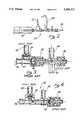
- FIG. 1is a schematic perspective view of a thermodilution injectate system
- FIG. 2is a partial cross-sectional view of the injectate assembly portion of the system of FIG. 1, taken along lines 2--2;
- FIG. 3is a cross-sectional view of a prior art version of a flow-through injectate assembly
- FIG. 4is a cross-sectional view of the flow-through injectate assembly of the present invention.
- FIG. 5is an enlarged cross-sectional view of an integral flow-through injectate assembly without a deflection means
- FIG. 6is a graph of the measured injectate temperature probe values over time utilizing the assembly of FIG. 5;
- FIG. 7is an enlarged cross-sectional view of a preferred embodiment of the integral flow-through injectate assembly of the present invention.
- FIG. 8is an enlarged cross-sectional view of an alternate embodiment of the integral flow-through injectate assembly of the present invention.
- FIG. 9is a graph of the measured injectate temperature probe values over time utilizing the assembly of FIG. 7.
- FIG. 10is a graph of the measured injectate temperature probe values over time utilizing a prior art injectate assembly.
- FIG. 1refers to a typical thermodilution system 10 for use in measuring the cardiac output of a patient.
- the system 10includes a conduit 12 having an inlet 14 and an outlet 16, a pump in the form of a syringe 18, a cooling container 20, a temperature probe 22, a flow-through assembly 24 adapted to cooperate with the probe 22, and a cardiac output computer 26.
- thermodilution system 10is utilized to inject a cooled injectate into a patient and to measure the temperature changes downstream in order to calculate cardiac output according to well known thermodilution techniques and principles.
- cooling container 20is used to cool saline from saline bottle 28 which travels along conduit 12 into container 20.
- Syringe 18is used to pump the cooled saline through conduit 12 and into the patient (not shown) as hereinafter described.
- the distal end of flow-through assembly 24is coupled to a thermodilution catheter 30 which forms part of conduit 12 and which includes balloon 32 at its distal end.
- Balloon 32is typically placed in the pulmonary artery of the patient so that outlet port 16, which is just proximal to balloon 32, is placed in the right atrium of the patient's heart to permit the cooled saline to mix with the patient's blood.
- Temperature probe 22is coupled to flow-through assembly 24 to sense the temperature of the cooled saline as it is injected into the patient. Probe 22 is also coupled to cardiac output computer 26, to which it transmits a signal representing the injectate temperature. Adjacent to balloon 32 is a downstream thermistor (not shown) which measures the temperature of the blood-injectate mixture after it is pumped through the atrium. The thermistor is also coupled, via catheter 30, to cardiac output computer 26, which processes temperature data from probe 22 and from the downstream thermistor to calculate cardiac output.
- FIG. 2illustrates flow-through assembly 24 of system 10 which is attached to syringe 18 and conduit 12.
- Syringe 18draws fluid from container 20 through conduit 12 and into catheter 30.
- Temperature probe 22is attached to the distal end of assembly 24 to monitor temperature that is directed through assembly 24 to catheter 30, and ultimately into the patient.
- FIG. 3illustrates a prior art flow-through assembly 24' that is usable with system 10.
- Assembly 24'is comprised of first check valve 34 and second check valve 36, as disclosed in U.S. Pat. No. 4,210,173, to Choksi et al., which are part of an integral unit connectable at its distal end, via first flow-through fitting 38, to temperature probe housing 40.
- Housing 40is connectable at its distal end, via second flow-through fitting 42, to the proximal end of catheter 30.
- the proximal end of assembly 24'has a first assembly port 44 which is in fluid communication with cooled container 20 through conduit 12, and a second assembly port 46 which is connectable to the syringe.
- temperature probe 22is placed in temperature probe receiving means 48, which is disposed within temperature probe housing 40, distal to first flow-through fitting 38 and proximal to second flow-through fitting 42.
- temperature probe receiving means 48which is disposed within temperature probe housing 40, distal to first flow-through fitting 38 and proximal to second flow-through fitting 42.
- FIG. 4illustrates the improved injectate flow through assembly 24 of the present invention which overcomes some of the disadvantages of prior art systems.
- First and second check valves 34 and 36are again utilized to control fluid flow as described above and are part of an integral flow through assembly 24.
- temperature probe receiving means 48is part of integral assembly 24 and is placed just proximal to the second check valve 36. Assembly 24 is thus directly coupled to catheter 30 through flow-through fitting 38. Since temperature probe housing 40 and second flow-through fitting 42 have been eliminated, the number of tubing and fluid connections is reduced.
- Syringe 18, which is attached to assembly 24 at port 46is utilized to draw cooled fluid, like saline, from cooled container 20 and inject the fluid through catheter 30 into the patient through outlet 16.
- Catheter 30is made of thermally insulated material which is sufficient to maintain the fluid at a fairly constant temperature until it exits outlet 16.
- thermodilution procedurePrior to undertaking the thermodilution procedure, saline is permitted to drip from bottle 28 through inlet 14 to conduit 12 and into cooled container 20 where it is chilled to a preferred temperature.
- Syringe 18has, up to now, been in a closed position.
- Plunger 50 of syringe 18is withdrawn and saline is drawn from cooled container 20 into syringe 18.
- the salineis injected into the patient through port 16 of catheter 30 by pushing plunger 50 back into syringe 18.
- a thermistor(not shown) is placed at the distal end of catheter 30 to measure the temperature of the blood and saline mixture which has been pumped through the auricle.
- the thermistoris connected to computer 26 via thermistor cable 54 through which it transmits the temperature reading.
- the computer 26is then able to compute the patient's cardiac output according to well known principles.
- the initial temperature measurement by temperature probe 22must be within a certain range of accuracy.
- Computer 26is programmed to utilize the lowest temperature sensed by probe 22.
- a problem that arises consequent to having temperature probe receiving means 48 as an integral part of assembly 24is the tendency for probe 22 to sense fluid of different temperature that may migrate within the assembly. The potential problem occurs after saline is injected into the patient and cold saline is then immediately withdrawn into the syringe again.
- the flow of saline from port 44 to syringe 18, as well as the migration of some saline to probe 22,is illustrated by arrows 56 in FIG. 5.
- FIG. 6,a graph of the measured injectate temperature probe values versus time, illustrates the aforementioned problem.
- the curve between points 58 and 60shows the temperature variation of the injectate during a first draw and injection and a short waiting period thereafter.
- Point 58is the point of highest temperature before drawing the saline for the first injection, which is also used by computer 26 to define the baseline temperature.
- the curve between points 58 and 62shows the injectate temperature variation, due to thermal contamination, during the draw phase of the first injection. Points 62 to 64 show a short waiting period just prior to the first injection.
- the curve between points 64 and 66represents the actual injection phase of the first injection, with point 66 representing the true injectate temperature.
- computer 26should utilize the lowest temperature at point 66.
- the curve between points 66 and 60represents the elapsed time between the first injection and the draw phase for the second injection.
- Points 60 through 68represent the temperature variation during the draw phase for the second injection, which immediately succeeds the first injection.
- Point 70which is the temperature of the contaminated saline, displays a lower temperature than point 66 and causes computer 26 to reset the baseline temperature it used to calculate cardiac output for the first injection.
- Point 70which becomes the new baseline for the cardiac output calculation, does not accurately reflect the lowest temperature of the injected fluid, resulting in an inaccurate thermodilution calculation.
- Points 58', 62', 66', and 70'illustrates another draw, injection, draw cycle wherein low temperature point 70' is erroneously utilized by computer 26.
- One of the features of the present inventionis a fluid flow regulating means which is used to interrupt or minimize the migrating fluid so that there is no significant thermal contamination during a withdrawal stroke.
- the regulating meansis a fluid deflection means. This embodiment is illustrated in FIG. 7.
- a fluid flow deflector means 72is placed distal from first port 44 at a proximal distance from probe receiving means 48. Deflector means 72 inhibits fluid particles, as indicated by arrows 74 from migrating distally along assembly 24. Deflector means 72 could be a roughened or grooved surface along the interior surface of assembly 24, or a series of bumps along the surface.
- deflector means 72is a narrowed orifice that reduces the cross-sectional flow area of the cooled fluid in assembly 24.
- deflector means 72could be any of the means for creating a disruption of flow as discussed above, as well as other equivalents.
- the regulating meansis an extended flow path 76 between injectate port 44 and temperature probe receiving means 48. Increasing the distance between these points reduces the thermal effect of the migrated fluid so that it will not significantly contaminate probe 22. By the time the saline has migrated to probe 22, as shown by arrows 78, it will have warmed sufficiently so that it does not significantly contaminate probe 22.
- FIG. 9is a graph of the measured injectate temperature probe values versus time utilizing assembly 24 of the present invention, as illustrated in FIG. 7.
- Points 58" and 60"are the end points of the temperature versus time curve during a fluid injection and a short waiting period thereafter.
- Points 58" through 62"represent the injectate temperature variation during the first draw.
- Points 62" through 64"represent a short waiting period and points 64" through 66" represent the actual injection, with point 66" indicating the lowest temperature point.
- Points 66" through 60”represent a short waiting period prior to the second draw and points 60" through 70" represent the second draw.
- FIG. 10graphically illustrates the use of a prior art injectate assembly.
- a comparison of FIG. 9 with FIG. 10graphically illustrates that the injectate assembly of the present invention performs as well as the cumbersome prior art injectate flow assemblies, which have the disadvantages discussed above.
- the assembly utilized in FIG. 10is of the type illustrated in FIG.
- FIGS. 9 and 10show that the integrated assembly of the present invention operates as effectively as the prior art, two part assembly of FIG. 3. Thus, it has been shown that it is possible to integrate the assembly, with the attendant benefits in cost, ease of manufacturing, reduction in connections, etc., and still provide for an accurate thermodilution calculation.
Landscapes
- Health & Medical Sciences (AREA)
- Life Sciences & Earth Sciences (AREA)
- Heart & Thoracic Surgery (AREA)
- Medical Informatics (AREA)
- Physics & Mathematics (AREA)
- Cardiology (AREA)
- Biophysics (AREA)
- Pathology (AREA)
- Engineering & Computer Science (AREA)
- Biomedical Technology (AREA)
- Hematology (AREA)
- Physiology (AREA)
- Molecular Biology (AREA)
- Surgery (AREA)
- Animal Behavior & Ethology (AREA)
- General Health & Medical Sciences (AREA)
- Public Health (AREA)
- Veterinary Medicine (AREA)
- Infusion, Injection, And Reservoir Apparatuses (AREA)
- Measuring Pulse, Heart Rate, Blood Pressure Or Blood Flow (AREA)
Abstract
Description
Claims (18)
Priority Applications (6)
| Application Number | Priority Date | Filing Date | Title |
|---|---|---|---|
| US08/025,002US5354272A (en) | 1993-03-02 | 1993-03-02 | Improved injectate delivery system |
| JP52012394AJP3428017B2 (en) | 1993-03-02 | 1994-03-01 | Injection liquid injection device |
| PCT/US1994/002230WO1994020017A1 (en) | 1993-03-02 | 1994-03-01 | Improved injectate delivery system |
| CA002155117ACA2155117C (en) | 1993-03-02 | 1994-03-01 | Improved injectable delivery system |
| EP94912171AEP0687160B1 (en) | 1993-03-02 | 1994-03-01 | Improved injectate delivery system |
| DE69420710TDE69420710T2 (en) | 1993-03-02 | 1994-03-01 | IMPROVEMENT ON AN INJECTION DEVICE |
Applications Claiming Priority (1)
| Application Number | Priority Date | Filing Date | Title |
|---|---|---|---|
| US08/025,002US5354272A (en) | 1993-03-02 | 1993-03-02 | Improved injectate delivery system |
Publications (1)
| Publication Number | Publication Date |
|---|---|
| US5354272Atrue US5354272A (en) | 1994-10-11 |
Family
ID=21823502
Family Applications (1)
| Application Number | Title | Priority Date | Filing Date |
|---|---|---|---|
| US08/025,002Expired - LifetimeUS5354272A (en) | 1993-03-02 | 1993-03-02 | Improved injectate delivery system |
Country Status (6)
| Country | Link |
|---|---|
| US (1) | US5354272A (en) |
| EP (1) | EP0687160B1 (en) |
| JP (1) | JP3428017B2 (en) |
| CA (1) | CA2155117C (en) |
| DE (1) | DE69420710T2 (en) |
| WO (1) | WO1994020017A1 (en) |
Cited By (50)
| Publication number | Priority date | Publication date | Assignee | Title |
|---|---|---|---|---|
| US5976112A (en)* | 1997-11-07 | 1999-11-02 | Lyza Weiss Jennings & Shea | Injector syringe |
| WO2001052921A3 (en)* | 2000-01-20 | 2002-01-31 | Nestle Sa | Valve arrangement |
| US6533804B2 (en) | 1998-01-23 | 2003-03-18 | Innercool Therapies, Inc. | Inflatable catheter for selective organ heating and cooling and method of using the same |
| US6551349B2 (en) | 1998-03-24 | 2003-04-22 | Innercool Therapies, Inc. | Selective organ cooling apparatus |
| US6576001B2 (en) | 2000-03-03 | 2003-06-10 | Innercool Therapies, Inc. | Lumen design for catheter |
| US6585752B2 (en) | 1998-06-23 | 2003-07-01 | Innercool Therapies, Inc. | Fever regulation method and apparatus |
| JP3428017B2 (en) | 1993-03-02 | 2003-07-22 | エドワーズ ライフサイエンシーズ コーポレイション | Injection liquid injection device |
| US6660028B2 (en) | 2000-06-02 | 2003-12-09 | Innercool Therapies, Inc. | Method for determining the effective thermal mass of a body or organ using a cooling catheter |
| US6676688B2 (en) | 1998-01-23 | 2004-01-13 | Innercool Therapies, Inc. | Method of making selective organ cooling catheter |
| US6676690B2 (en) | 1999-10-07 | 2004-01-13 | Innercool Therapies, Inc. | Inflatable heat transfer apparatus |
| US6692488B2 (en) | 1998-01-23 | 2004-02-17 | Innercool Therapies, Inc. | Apparatus for cell necrosis |
| US6719723B2 (en) | 2000-12-06 | 2004-04-13 | Innercool Therapies, Inc. | Multipurpose catheter assembly |
| US6719779B2 (en) | 2000-11-07 | 2004-04-13 | Innercool Therapies, Inc. | Circulation set for temperature-controlled catheter and method of using the same |
| US6905509B2 (en) | 1998-01-23 | 2005-06-14 | Innercool Therapies, Inc. | Selective organ cooling catheter with guidewire apparatus and temperature-monitoring device |
| US7018399B2 (en) | 1998-06-23 | 2006-03-28 | Innercool Therapies, Inc. | Method of making selective organ cooling catheter |
| US20070088216A1 (en)* | 2005-10-19 | 2007-04-19 | Up Management Gmbh & Co Med-Systems Kg | Device and method for injectate duration measurement and temperature measurement |
| US7300453B2 (en) | 2003-02-24 | 2007-11-27 | Innercool Therapies, Inc. | System and method for inducing hypothermia with control and determination of catheter pressure |
| US7371254B2 (en) | 1998-01-23 | 2008-05-13 | Innercool Therapies, Inc. | Medical procedure |
| US7615007B2 (en) | 2006-10-04 | 2009-11-10 | Dexcom, Inc. | Analyte sensor |
| US7640048B2 (en) | 2004-07-13 | 2009-12-29 | Dexcom, Inc. | Analyte sensor |
| US7783333B2 (en) | 2004-07-13 | 2010-08-24 | Dexcom, Inc. | Transcutaneous medical device with variable stiffness |
| US7857781B2 (en) | 1998-04-21 | 2010-12-28 | Zoll Circulation, Inc. | Indwelling heat exchange catheter and method of using same |
| US8275438B2 (en) | 2006-10-04 | 2012-09-25 | Dexcom, Inc. | Analyte sensor |
| US8287453B2 (en) | 2003-12-05 | 2012-10-16 | Dexcom, Inc. | Analyte sensor |
| US8298142B2 (en) | 2006-10-04 | 2012-10-30 | Dexcom, Inc. | Analyte sensor |
| US8364230B2 (en) | 2006-10-04 | 2013-01-29 | Dexcom, Inc. | Analyte sensor |
| US8364231B2 (en) | 2006-10-04 | 2013-01-29 | Dexcom, Inc. | Analyte sensor |
| US8396528B2 (en) | 2008-03-25 | 2013-03-12 | Dexcom, Inc. | Analyte sensor |
| US8425416B2 (en) | 2006-10-04 | 2013-04-23 | Dexcom, Inc. | Analyte sensor |
| US8425417B2 (en) | 2003-12-05 | 2013-04-23 | Dexcom, Inc. | Integrated device for continuous in vivo analyte detection and simultaneous control of an infusion device |
| US8447376B2 (en) | 2006-10-04 | 2013-05-21 | Dexcom, Inc. | Analyte sensor |
| US8449464B2 (en) | 2006-10-04 | 2013-05-28 | Dexcom, Inc. | Analyte sensor |
| US8478377B2 (en) | 2006-10-04 | 2013-07-02 | Dexcom, Inc. | Analyte sensor |
| US8562528B2 (en) | 2006-10-04 | 2013-10-22 | Dexcom, Inc. | Analyte sensor |
| US8562558B2 (en) | 2007-06-08 | 2013-10-22 | Dexcom, Inc. | Integrated medicament delivery device for use with continuous analyte sensor |
| US8626257B2 (en) | 2003-08-01 | 2014-01-07 | Dexcom, Inc. | Analyte sensor |
| US8886273B2 (en) | 2003-08-01 | 2014-11-11 | Dexcom, Inc. | Analyte sensor |
| EP2506889B1 (en) | 2009-12-03 | 2018-06-13 | Jean-Pierre Peters | Fluid interconnection set with particle filter |
| US10524703B2 (en) | 2004-07-13 | 2020-01-07 | Dexcom, Inc. | Transcutaneous analyte sensor |
| US10610137B2 (en) | 2005-03-10 | 2020-04-07 | Dexcom, Inc. | System and methods for processing analyte sensor data for sensor calibration |
| US10813577B2 (en) | 2005-06-21 | 2020-10-27 | Dexcom, Inc. | Analyte sensor |
| US10835672B2 (en) | 2004-02-26 | 2020-11-17 | Dexcom, Inc. | Integrated insulin delivery system with continuous glucose sensor |
| US10966609B2 (en) | 2004-02-26 | 2021-04-06 | Dexcom, Inc. | Integrated medicament delivery device for use with continuous analyte sensor |
| US10980461B2 (en) | 2008-11-07 | 2021-04-20 | Dexcom, Inc. | Advanced analyte sensor calibration and error detection |
| US11000215B1 (en) | 2003-12-05 | 2021-05-11 | Dexcom, Inc. | Analyte sensor |
| US11246990B2 (en) | 2004-02-26 | 2022-02-15 | Dexcom, Inc. | Integrated delivery device for continuous glucose sensor |
| US11331022B2 (en) | 2017-10-24 | 2022-05-17 | Dexcom, Inc. | Pre-connected analyte sensors |
| US11350862B2 (en) | 2017-10-24 | 2022-06-07 | Dexcom, Inc. | Pre-connected analyte sensors |
| US11399745B2 (en) | 2006-10-04 | 2022-08-02 | Dexcom, Inc. | Dual electrode system for a continuous analyte sensor |
| US11633133B2 (en) | 2003-12-05 | 2023-04-25 | Dexcom, Inc. | Dual electrode system for a continuous analyte sensor |
Families Citing this family (2)
| Publication number | Priority date | Publication date | Assignee | Title |
|---|---|---|---|---|
| DE19738942A1 (en)* | 1997-09-05 | 1999-03-25 | Pulsion Verwaltungs Gmbh & Co | Method and device for determining the injection time and duration of injection in thermodilution measurements |
| DE102008026708B4 (en)* | 2008-06-04 | 2014-01-23 | Iprm Intellectual Property Rights Management Ag | Device for determining the blood volume and / or blood volume flow and method for operating the same |
Citations (21)
| Publication number | Priority date | Publication date | Assignee | Title |
|---|---|---|---|---|
| US4103686A (en)* | 1977-03-29 | 1978-08-01 | Burron Medical Products, Inc. | Dual valve assembly |
| US4246932A (en)* | 1979-10-18 | 1981-01-27 | Burron Medical, Inc. | Multiple additive valve assembly |
| US4310017A (en)* | 1980-01-30 | 1982-01-12 | Burron Medical Inc. | Backflow check valve for use with IV administration sets |
| US4535820A (en)* | 1984-05-24 | 1985-08-20 | Burron Medical Inc. | Normally closed check valve |
| US4540027A (en)* | 1982-09-17 | 1985-09-10 | Transcodan, Sven Husted-Andersen Gmbh & Co. Kg | Check valve for infusion and transfusion apparatus |
| US4556086A (en)* | 1984-09-26 | 1985-12-03 | Burron Medical Inc. | Dual disc low pressure back-check valve |
| US4580573A (en)* | 1983-10-20 | 1986-04-08 | Medical Device Development Corporation, Inc. | Catheter introducer |
| DE3503320A1 (en)* | 1985-01-31 | 1986-08-07 | Baxter Travenol Laboratories, Inc., Deerfield, Ill. | Multi-way valve |
| DE3518575A1 (en)* | 1985-04-19 | 1986-10-23 | Baxter Travenol Laboratories, Inc., Deerfield, Ill. | Multi-way valve |
| US4626243A (en)* | 1985-06-21 | 1986-12-02 | Applied Biomedical Corporation | Gravity-independent infusion system |
| US4683916A (en)* | 1986-09-25 | 1987-08-04 | Burron Medical Inc. | Normally closed automatic reflux valve |
| US4703759A (en)* | 1986-05-20 | 1987-11-03 | Hewlett-Packard Company | Flush valve device |
| US4729401A (en)* | 1987-01-29 | 1988-03-08 | Burron Medical Inc. | Aspiration assembly having dual co-axial check valves |
| US4915688A (en)* | 1987-12-03 | 1990-04-10 | Baxter International Inc. | Apparatus for administering solution to a patient |
| US4919167A (en)* | 1989-03-17 | 1990-04-24 | Manska Wayne E | Check valve |
| US5022422A (en)* | 1990-07-30 | 1991-06-11 | Imed Corporation | Ball valve |
| US5037390A (en)* | 1989-12-28 | 1991-08-06 | Kenneth Raines | System and method for mixing parenteral nutrition solutions |
| US5098405A (en)* | 1991-01-31 | 1992-03-24 | Becton, Dickinson And Company | Apparatus and method for a side port cathether adapter with a one piece integral combination valve |
| EP0489297A1 (en)* | 1990-12-04 | 1992-06-10 | Klaus Dipl.-Ing. Mokros | Infusionsystem including a diverting device for a bolus volume |
| US5127904A (en)* | 1988-08-11 | 1992-07-07 | Loo George D H | Improved needle-less parenteral fluid injector |
| US5221271A (en)* | 1991-08-15 | 1993-06-22 | Medex, Inc. | Sample site with flow directors |
Family Cites Families (2)
| Publication number | Priority date | Publication date | Assignee | Title |
|---|---|---|---|---|
| DE3603463A1 (en)* | 1986-02-05 | 1987-08-06 | Plastik Fuer Die Medizin Pfm | Intermediate valve chamber for medical purposes |
| US5354272A (en) | 1993-03-02 | 1994-10-11 | Baxter International Inc. | Improved injectate delivery system |
- 1993
- 1993-03-02USUS08/025,002patent/US5354272A/ennot_activeExpired - Lifetime
- 1994
- 1994-03-01WOPCT/US1994/002230patent/WO1994020017A1/enactiveIP Right Grant
- 1994-03-01CACA002155117Apatent/CA2155117C/ennot_activeExpired - Lifetime
- 1994-03-01EPEP94912171Apatent/EP0687160B1/ennot_activeExpired - Lifetime
- 1994-03-01JPJP52012394Apatent/JP3428017B2/ennot_activeExpired - Lifetime
- 1994-03-01DEDE69420710Tpatent/DE69420710T2/ennot_activeExpired - Lifetime
Patent Citations (21)
| Publication number | Priority date | Publication date | Assignee | Title |
|---|---|---|---|---|
| US4103686A (en)* | 1977-03-29 | 1978-08-01 | Burron Medical Products, Inc. | Dual valve assembly |
| US4246932A (en)* | 1979-10-18 | 1981-01-27 | Burron Medical, Inc. | Multiple additive valve assembly |
| US4310017A (en)* | 1980-01-30 | 1982-01-12 | Burron Medical Inc. | Backflow check valve for use with IV administration sets |
| US4540027A (en)* | 1982-09-17 | 1985-09-10 | Transcodan, Sven Husted-Andersen Gmbh & Co. Kg | Check valve for infusion and transfusion apparatus |
| US4580573A (en)* | 1983-10-20 | 1986-04-08 | Medical Device Development Corporation, Inc. | Catheter introducer |
| US4535820A (en)* | 1984-05-24 | 1985-08-20 | Burron Medical Inc. | Normally closed check valve |
| US4556086A (en)* | 1984-09-26 | 1985-12-03 | Burron Medical Inc. | Dual disc low pressure back-check valve |
| DE3503320A1 (en)* | 1985-01-31 | 1986-08-07 | Baxter Travenol Laboratories, Inc., Deerfield, Ill. | Multi-way valve |
| DE3518575A1 (en)* | 1985-04-19 | 1986-10-23 | Baxter Travenol Laboratories, Inc., Deerfield, Ill. | Multi-way valve |
| US4626243A (en)* | 1985-06-21 | 1986-12-02 | Applied Biomedical Corporation | Gravity-independent infusion system |
| US4703759A (en)* | 1986-05-20 | 1987-11-03 | Hewlett-Packard Company | Flush valve device |
| US4683916A (en)* | 1986-09-25 | 1987-08-04 | Burron Medical Inc. | Normally closed automatic reflux valve |
| US4729401A (en)* | 1987-01-29 | 1988-03-08 | Burron Medical Inc. | Aspiration assembly having dual co-axial check valves |
| US4915688A (en)* | 1987-12-03 | 1990-04-10 | Baxter International Inc. | Apparatus for administering solution to a patient |
| US5127904A (en)* | 1988-08-11 | 1992-07-07 | Loo George D H | Improved needle-less parenteral fluid injector |
| US4919167A (en)* | 1989-03-17 | 1990-04-24 | Manska Wayne E | Check valve |
| US5037390A (en)* | 1989-12-28 | 1991-08-06 | Kenneth Raines | System and method for mixing parenteral nutrition solutions |
| US5022422A (en)* | 1990-07-30 | 1991-06-11 | Imed Corporation | Ball valve |
| EP0489297A1 (en)* | 1990-12-04 | 1992-06-10 | Klaus Dipl.-Ing. Mokros | Infusionsystem including a diverting device for a bolus volume |
| US5098405A (en)* | 1991-01-31 | 1992-03-24 | Becton, Dickinson And Company | Apparatus and method for a side port cathether adapter with a one piece integral combination valve |
| US5221271A (en)* | 1991-08-15 | 1993-06-22 | Medex, Inc. | Sample site with flow directors |
Cited By (129)
| Publication number | Priority date | Publication date | Assignee | Title |
|---|---|---|---|---|
| JP3428017B2 (en) | 1993-03-02 | 2003-07-22 | エドワーズ ライフサイエンシーズ コーポレイション | Injection liquid injection device |
| US5976112A (en)* | 1997-11-07 | 1999-11-02 | Lyza Weiss Jennings & Shea | Injector syringe |
| US7651518B2 (en) | 1998-01-23 | 2010-01-26 | Innercool Therapies, Inc. | Inflatable catheter for selective organ heating and cooling and method of using the same |
| US6692488B2 (en) | 1998-01-23 | 2004-02-17 | Innercool Therapies, Inc. | Apparatus for cell necrosis |
| US6540771B2 (en) | 1998-01-23 | 2003-04-01 | Innercool Therapies, Inc. | Inflatable catheter for selective organ heating and cooling and method of using the same |
| US8163000B2 (en) | 1998-01-23 | 2012-04-24 | Innercool Therapies, Inc. | Selective organ cooling catheter with guidewire apparatus and temperature-monitoring device |
| US7294142B2 (en) | 1998-01-23 | 2007-11-13 | Innercool Therapies | Selective organ cooling catheter with guidewire apparatus and temperature-monitoring device |
| US6533804B2 (en) | 1998-01-23 | 2003-03-18 | Innercool Therapies, Inc. | Inflatable catheter for selective organ heating and cooling and method of using the same |
| US6648908B2 (en) | 1998-01-23 | 2003-11-18 | Innercool Therapies, Inc. | Inflatable catheter for selective organ heating and cooling and method of using the same |
| US7951183B2 (en) | 1998-01-23 | 2011-05-31 | Innercool Therapies, Inc. | Medical procedure |
| US6676689B2 (en) | 1998-01-23 | 2004-01-13 | Innercool Therapies, Inc. | Inflatable catheter for selective organ heating and cooling and method of using the same |
| US6676688B2 (en) | 1998-01-23 | 2004-01-13 | Innercool Therapies, Inc. | Method of making selective organ cooling catheter |
| US6905509B2 (en) | 1998-01-23 | 2005-06-14 | Innercool Therapies, Inc. | Selective organ cooling catheter with guidewire apparatus and temperature-monitoring device |
| US7094253B2 (en) | 1998-01-23 | 2006-08-22 | Innercool Therapies, Inc. | Fever regulation method and apparatus |
| US6695873B2 (en) | 1998-01-23 | 2004-02-24 | Innercool Therapies, Inc. | Inflatable catheter for selective organ heating and cooling and method of using the same |
| US7371254B2 (en) | 1998-01-23 | 2008-05-13 | Innercool Therapies, Inc. | Medical procedure |
| US7766949B2 (en) | 1998-01-23 | 2010-08-03 | Innercool Therapies, Inc. | Fever regulation method and apparatus |
| US6551349B2 (en) | 1998-03-24 | 2003-04-22 | Innercool Therapies, Inc. | Selective organ cooling apparatus |
| US7857781B2 (en) | 1998-04-21 | 2010-12-28 | Zoll Circulation, Inc. | Indwelling heat exchange catheter and method of using same |
| US6585752B2 (en) | 1998-06-23 | 2003-07-01 | Innercool Therapies, Inc. | Fever regulation method and apparatus |
| US7018399B2 (en) | 1998-06-23 | 2006-03-28 | Innercool Therapies, Inc. | Method of making selective organ cooling catheter |
| US6676690B2 (en) | 1999-10-07 | 2004-01-13 | Innercool Therapies, Inc. | Inflatable heat transfer apparatus |
| US7052508B2 (en) | 1999-10-07 | 2006-05-30 | Innercool Therapies, Inc. | Inflatable heat transfer apparatus |
| US6843780B2 (en) | 2000-01-20 | 2005-01-18 | Nestec S.A. | Valve arrangement |
| WO2001052921A3 (en)* | 2000-01-20 | 2002-01-31 | Nestle Sa | Valve arrangement |
| US6576001B2 (en) | 2000-03-03 | 2003-06-10 | Innercool Therapies, Inc. | Lumen design for catheter |
| US6660028B2 (en) | 2000-06-02 | 2003-12-09 | Innercool Therapies, Inc. | Method for determining the effective thermal mass of a body or organ using a cooling catheter |
| US7211105B2 (en) | 2000-06-02 | 2007-05-01 | Innercool Therapias, Inc. | Method for determining the effective thermal mass of a body or organ using a cooling catheter |
| US6719779B2 (en) | 2000-11-07 | 2004-04-13 | Innercool Therapies, Inc. | Circulation set for temperature-controlled catheter and method of using the same |
| US7004960B2 (en) | 2000-11-07 | 2006-02-28 | Innercool Therapies, Inc. | Circulation set for temperature-controlled catheter and method of using the same |
| US6719723B2 (en) | 2000-12-06 | 2004-04-13 | Innercool Therapies, Inc. | Multipurpose catheter assembly |
| US6979345B2 (en) | 2000-12-06 | 2005-12-27 | Innercool Therapies, Inc. | Multipurpose catheter assembly |
| US7300453B2 (en) | 2003-02-24 | 2007-11-27 | Innercool Therapies, Inc. | System and method for inducing hypothermia with control and determination of catheter pressure |
| US8626257B2 (en) | 2003-08-01 | 2014-01-07 | Dexcom, Inc. | Analyte sensor |
| US8886273B2 (en) | 2003-08-01 | 2014-11-11 | Dexcom, Inc. | Analyte sensor |
| US10052055B2 (en) | 2003-08-01 | 2018-08-21 | Dexcom, Inc. | Analyte sensor |
| US8425417B2 (en) | 2003-12-05 | 2013-04-23 | Dexcom, Inc. | Integrated device for continuous in vivo analyte detection and simultaneous control of an infusion device |
| US11000215B1 (en) | 2003-12-05 | 2021-05-11 | Dexcom, Inc. | Analyte sensor |
| US11020031B1 (en) | 2003-12-05 | 2021-06-01 | Dexcom, Inc. | Analyte sensor |
| US8287453B2 (en) | 2003-12-05 | 2012-10-16 | Dexcom, Inc. | Analyte sensor |
| US11633133B2 (en) | 2003-12-05 | 2023-04-25 | Dexcom, Inc. | Dual electrode system for a continuous analyte sensor |
| US12102410B2 (en) | 2004-02-26 | 2024-10-01 | Dexcom, Inc | Integrated medicament delivery device for use with continuous analyte sensor |
| US12226617B2 (en) | 2004-02-26 | 2025-02-18 | Dexcom, Inc. | Integrated delivery device for continuous glucose sensor |
| US10966609B2 (en) | 2004-02-26 | 2021-04-06 | Dexcom, Inc. | Integrated medicament delivery device for use with continuous analyte sensor |
| US10835672B2 (en) | 2004-02-26 | 2020-11-17 | Dexcom, Inc. | Integrated insulin delivery system with continuous glucose sensor |
| US11246990B2 (en) | 2004-02-26 | 2022-02-15 | Dexcom, Inc. | Integrated delivery device for continuous glucose sensor |
| US12115357B2 (en) | 2004-02-26 | 2024-10-15 | Dexcom, Inc. | Integrated delivery device for continuous glucose sensor |
| US10980452B2 (en) | 2004-07-13 | 2021-04-20 | Dexcom, Inc. | Analyte sensor |
| US10709362B2 (en) | 2004-07-13 | 2020-07-14 | Dexcom, Inc. | Analyte sensor |
| US11883164B2 (en) | 2004-07-13 | 2024-01-30 | Dexcom, Inc. | System and methods for processing analyte sensor data for sensor calibration |
| US7640048B2 (en) | 2004-07-13 | 2009-12-29 | Dexcom, Inc. | Analyte sensor |
| US11064917B2 (en) | 2004-07-13 | 2021-07-20 | Dexcom, Inc. | Analyte sensor |
| US11045120B2 (en) | 2004-07-13 | 2021-06-29 | Dexcom, Inc. | Analyte sensor |
| US11026605B1 (en) | 2004-07-13 | 2021-06-08 | Dexcom, Inc. | Analyte sensor |
| US7783333B2 (en) | 2004-07-13 | 2010-08-24 | Dexcom, Inc. | Transcutaneous medical device with variable stiffness |
| US10993641B2 (en) | 2004-07-13 | 2021-05-04 | Dexcom, Inc. | Analyte sensor |
| US8750955B2 (en) | 2004-07-13 | 2014-06-10 | Dexcom, Inc. | Analyte sensor |
| US10993642B2 (en) | 2004-07-13 | 2021-05-04 | Dexcom, Inc. | Analyte sensor |
| US8812072B2 (en) | 2004-07-13 | 2014-08-19 | Dexcom, Inc. | Transcutaneous medical device with variable stiffness |
| US7857760B2 (en) | 2004-07-13 | 2010-12-28 | Dexcom, Inc. | Analyte sensor |
| US10932700B2 (en) | 2004-07-13 | 2021-03-02 | Dexcom, Inc. | Analyte sensor |
| US10918315B2 (en) | 2004-07-13 | 2021-02-16 | Dexcom, Inc. | Analyte sensor |
| US10918314B2 (en) | 2004-07-13 | 2021-02-16 | Dexcom, Inc. | Analyte sensor |
| US10918313B2 (en) | 2004-07-13 | 2021-02-16 | Dexcom, Inc. | Analyte sensor |
| US10827956B2 (en) | 2004-07-13 | 2020-11-10 | Dexcom, Inc. | Analyte sensor |
| US10813576B2 (en) | 2004-07-13 | 2020-10-27 | Dexcom, Inc. | Analyte sensor |
| US10799159B2 (en) | 2004-07-13 | 2020-10-13 | Dexcom, Inc. | Analyte sensor |
| US10524703B2 (en) | 2004-07-13 | 2020-01-07 | Dexcom, Inc. | Transcutaneous analyte sensor |
| US10799158B2 (en) | 2004-07-13 | 2020-10-13 | Dexcom, Inc. | Analyte sensor |
| US10722152B2 (en) | 2004-07-13 | 2020-07-28 | Dexcom, Inc. | Analyte sensor |
| US10709363B2 (en) | 2004-07-13 | 2020-07-14 | Dexcom, Inc. | Analyte sensor |
| US10918316B2 (en) | 2005-03-10 | 2021-02-16 | Dexcom, Inc. | System and methods for processing analyte sensor data for sensor calibration |
| US11051726B2 (en) | 2005-03-10 | 2021-07-06 | Dexcom, Inc. | System and methods for processing analyte sensor data for sensor calibration |
| US10610135B2 (en) | 2005-03-10 | 2020-04-07 | Dexcom, Inc. | System and methods for processing analyte sensor data for sensor calibration |
| US10709364B2 (en) | 2005-03-10 | 2020-07-14 | Dexcom, Inc. | System and methods for processing analyte sensor data for sensor calibration |
| US10610136B2 (en) | 2005-03-10 | 2020-04-07 | Dexcom, Inc. | System and methods for processing analyte sensor data for sensor calibration |
| US10716498B2 (en) | 2005-03-10 | 2020-07-21 | Dexcom, Inc. | System and methods for processing analyte sensor data for sensor calibration |
| US10610137B2 (en) | 2005-03-10 | 2020-04-07 | Dexcom, Inc. | System and methods for processing analyte sensor data for sensor calibration |
| US10743801B2 (en) | 2005-03-10 | 2020-08-18 | Dexcom, Inc. | System and methods for processing analyte sensor data for sensor calibration |
| US10918317B2 (en) | 2005-03-10 | 2021-02-16 | Dexcom, Inc. | System and methods for processing analyte sensor data for sensor calibration |
| US10925524B2 (en) | 2005-03-10 | 2021-02-23 | Dexcom, Inc. | System and methods for processing analyte sensor data for sensor calibration |
| US11000213B2 (en) | 2005-03-10 | 2021-05-11 | Dexcom, Inc. | System and methods for processing analyte sensor data for sensor calibration |
| US10898114B2 (en) | 2005-03-10 | 2021-01-26 | Dexcom, Inc. | System and methods for processing analyte sensor data for sensor calibration |
| US10617336B2 (en) | 2005-03-10 | 2020-04-14 | Dexcom, Inc. | System and methods for processing analyte sensor data for sensor calibration |
| US10918318B2 (en) | 2005-03-10 | 2021-02-16 | Dexcom, Inc. | System and methods for processing analyte sensor data for sensor calibration |
| US10856787B2 (en) | 2005-03-10 | 2020-12-08 | Dexcom, Inc. | System and methods for processing analyte sensor data for sensor calibration |
| US10813577B2 (en) | 2005-06-21 | 2020-10-27 | Dexcom, Inc. | Analyte sensor |
| EP1776921A3 (en)* | 2005-10-19 | 2007-12-12 | UP Management GmbH & Co Med-Systems KG | Device and method for injectate duration measurement and temperature measurement |
| EP1776921A2 (en) | 2005-10-19 | 2007-04-25 | UP Management GmbH & Co Med-Systems KG | Device and method for injectate duration measurement and temperature measurement |
| US20070088216A1 (en)* | 2005-10-19 | 2007-04-19 | Up Management Gmbh & Co Med-Systems Kg | Device and method for injectate duration measurement and temperature measurement |
| US7615007B2 (en) | 2006-10-04 | 2009-11-10 | Dexcom, Inc. | Analyte sensor |
| US8447376B2 (en) | 2006-10-04 | 2013-05-21 | Dexcom, Inc. | Analyte sensor |
| US10349873B2 (en) | 2006-10-04 | 2019-07-16 | Dexcom, Inc. | Analyte sensor |
| US9451908B2 (en) | 2006-10-04 | 2016-09-27 | Dexcom, Inc. | Analyte sensor |
| US8911367B2 (en) | 2006-10-04 | 2014-12-16 | Dexcom, Inc. | Analyte sensor |
| US8275438B2 (en) | 2006-10-04 | 2012-09-25 | Dexcom, Inc. | Analyte sensor |
| US8364230B2 (en) | 2006-10-04 | 2013-01-29 | Dexcom, Inc. | Analyte sensor |
| US8364231B2 (en) | 2006-10-04 | 2013-01-29 | Dexcom, Inc. | Analyte sensor |
| US8774886B2 (en) | 2006-10-04 | 2014-07-08 | Dexcom, Inc. | Analyte sensor |
| US11399745B2 (en) | 2006-10-04 | 2022-08-02 | Dexcom, Inc. | Dual electrode system for a continuous analyte sensor |
| US8425416B2 (en) | 2006-10-04 | 2013-04-23 | Dexcom, Inc. | Analyte sensor |
| US11382539B2 (en) | 2006-10-04 | 2022-07-12 | Dexcom, Inc. | Analyte sensor |
| US7775975B2 (en) | 2006-10-04 | 2010-08-17 | Dexcom, Inc. | Analyte sensor |
| US8562528B2 (en) | 2006-10-04 | 2013-10-22 | Dexcom, Inc. | Analyte sensor |
| US8532730B2 (en) | 2006-10-04 | 2013-09-10 | Dexcom, Inc. | Analyte sensor |
| US8298142B2 (en) | 2006-10-04 | 2012-10-30 | Dexcom, Inc. | Analyte sensor |
| US8478377B2 (en) | 2006-10-04 | 2013-07-02 | Dexcom, Inc. | Analyte sensor |
| US8449464B2 (en) | 2006-10-04 | 2013-05-28 | Dexcom, Inc. | Analyte sensor |
| US12394120B2 (en) | 2007-06-08 | 2025-08-19 | Dexcom, Inc. | Integrated medicament delivery device for use with continuous analyte sensor |
| US10403012B2 (en) | 2007-06-08 | 2019-09-03 | Dexcom, Inc. | Integrated medicament delivery device for use with continuous analyte sensor |
| US9741139B2 (en) | 2007-06-08 | 2017-08-22 | Dexcom, Inc. | Integrated medicament delivery device for use with continuous analyte sensor |
| US11373347B2 (en) | 2007-06-08 | 2022-06-28 | Dexcom, Inc. | Integrated medicament delivery device for use with continuous analyte sensor |
| US8562558B2 (en) | 2007-06-08 | 2013-10-22 | Dexcom, Inc. | Integrated medicament delivery device for use with continuous analyte sensor |
| US11744943B2 (en) | 2007-10-09 | 2023-09-05 | Dexcom, Inc. | Integrated insulin delivery system with continuous glucose sensor |
| US11160926B1 (en) | 2007-10-09 | 2021-11-02 | Dexcom, Inc. | Pre-connected analyte sensors |
| US12246166B2 (en) | 2007-10-09 | 2025-03-11 | Dexcom, Inc. | Integrated insulin delivery system with continuous glucose sensor |
| US12397113B2 (en) | 2007-10-09 | 2025-08-26 | Dexcom, Inc. | Integrated insulin delivery system with continuous glucose sensor |
| US12397110B2 (en) | 2007-10-09 | 2025-08-26 | Dexcom, Inc. | Integrated insulin delivery system with continuous glucose sensor |
| US8396528B2 (en) | 2008-03-25 | 2013-03-12 | Dexcom, Inc. | Analyte sensor |
| US10602968B2 (en) | 2008-03-25 | 2020-03-31 | Dexcom, Inc. | Analyte sensor |
| US11896374B2 (en) | 2008-03-25 | 2024-02-13 | Dexcom, Inc. | Analyte sensor |
| US10980461B2 (en) | 2008-11-07 | 2021-04-20 | Dexcom, Inc. | Advanced analyte sensor calibration and error detection |
| EP2506889B1 (en) | 2009-12-03 | 2018-06-13 | Jean-Pierre Peters | Fluid interconnection set with particle filter |
| US11382540B2 (en) | 2017-10-24 | 2022-07-12 | Dexcom, Inc. | Pre-connected analyte sensors |
| US12150250B2 (en) | 2017-10-24 | 2024-11-19 | Dexcom, Inc. | Pre-connected analyte sensors |
| US11943876B2 (en) | 2017-10-24 | 2024-03-26 | Dexcom, Inc. | Pre-connected analyte sensors |
| US11706876B2 (en) | 2017-10-24 | 2023-07-18 | Dexcom, Inc. | Pre-connected analyte sensors |
| US11350862B2 (en) | 2017-10-24 | 2022-06-07 | Dexcom, Inc. | Pre-connected analyte sensors |
| US11331022B2 (en) | 2017-10-24 | 2022-05-17 | Dexcom, Inc. | Pre-connected analyte sensors |
Also Published As
| Publication number | Publication date |
|---|---|
| WO1994020017A1 (en) | 1994-09-15 |
| EP0687160B1 (en) | 1999-09-15 |
| JP3428017B2 (en) | 2003-07-22 |
| CA2155117A1 (en) | 1994-09-15 |
| DE69420710D1 (en) | 1999-10-21 |
| DE69420710T2 (en) | 2000-06-08 |
| EP0687160A1 (en) | 1995-12-20 |
| CA2155117C (en) | 2005-01-11 |
| JPH08507455A (en) | 1996-08-13 |
Similar Documents
| Publication | Publication Date | Title |
|---|---|---|
| US5354272A (en) | Improved injectate delivery system | |
| US6672172B2 (en) | Triggered flow measurement | |
| US4153048A (en) | Thermodilution catheter and method | |
| US4817624A (en) | Mini-bolus technique for thermodilution cardiac output measurements | |
| US8016766B2 (en) | Central venous catheter assembly for measuring physiological data for cardiac output determination and method of determining cardiac output | |
| JP3692035B2 (en) | Narrow channel flow measurement method including temperature and pressure sensors | |
| US4941475A (en) | Thermodilution by heat exchange | |
| US5806528A (en) | In-line temperature sensing devices, systems and methods | |
| JPH11192211A (en) | Method add device to determine injection stating time and injection continuing time in thermodilution measurement | |
| MXPA06013714A (en) | Flow monitoring devices and methods of use. | |
| US4730623A (en) | Cardiac output estimation method and apparatus | |
| JP4909982B2 (en) | System for determining cardiac output | |
| AU606811B2 (en) | Apparatus and method for determining cardiac output by thermodilution without injection | |
| US11089971B2 (en) | Thermodilution injectate measurement and control | |
| JP3184831B2 (en) | A device for simultaneous simultaneous administration of multiple infusions or drug solutions | |
| US20240032811A1 (en) | Indicator temperature compensation in flow rate calculation | |
| Hirzel et al. | Evaluation of the thermodilution technique for measuring coronary sinus blood flow | |
| JPH0226532A (en) | Injection calorimeter measuring device | |
| KR20070016155A (en) | Flow monitoring device for IV line based on differential pressure measurement | |
| JPH021229A (en) | Flow rate measuring catheter | |
| JPH04161141A (en) | Heart rate outgoing quantity measuring method |
Legal Events
| Date | Code | Title | Description |
|---|---|---|---|
| AS | Assignment | Owner name:BAXTER INTERNATIONAL INC., ILLINOIS Free format text:ASSIGNMENT OF ASSIGNORS INTEREST.;ASSIGNORS:SWENDSON, DAVID L.;EVANS, DAVID J.;ATTAL, LUCIEN;REEL/FRAME:006518/0879 Effective date:19930302 | |
| STCF | Information on status: patent grant | Free format text:PATENTED CASE | |
| FEPP | Fee payment procedure | Free format text:PAYOR NUMBER ASSIGNED (ORIGINAL EVENT CODE: ASPN); ENTITY STATUS OF PATENT OWNER: LARGE ENTITY | |
| AS | Assignment | Owner name:BAXTER INTERNATIONAL INC., ILLINOIS Free format text:ASSIGNMENT OF ASSIGNORS INTEREST;ASSIGNORS:ATTAL, LUCIEN;SWENDSON, DAVID L.;REEL/FRAME:007840/0122;SIGNING DATES FROM 19960226 TO 19960227 | |
| FPAY | Fee payment | Year of fee payment:4 | |
| AS | Assignment | Owner name:EDWARDS LIFESCIENCES CORPORATION, CALIFORNIA Free format text:ASSIGNMENT OF ASSIGNORS INTEREST;ASSIGNOR:BAXTER INTERNATIONAL INC.;REEL/FRAME:010901/0274 Effective date:20000609 | |
| FEPP | Fee payment procedure | Free format text:PAYER NUMBER DE-ASSIGNED (ORIGINAL EVENT CODE: RMPN); ENTITY STATUS OF PATENT OWNER: LARGE ENTITY Free format text:PAYOR NUMBER ASSIGNED (ORIGINAL EVENT CODE: ASPN); ENTITY STATUS OF PATENT OWNER: LARGE ENTITY | |
| FPAY | Fee payment | Year of fee payment:8 | |
| REMI | Maintenance fee reminder mailed | ||
| FPAY | Fee payment | Year of fee payment:12 |