US5353548A - Curl spring shoe based window balance system - Google Patents
Curl spring shoe based window balance systemDownload PDFInfo
- Publication number
- US5353548A US5353548AUS08/040,457US4045793AUS5353548AUS 5353548 AUS5353548 AUS 5353548AUS 4045793 AUS4045793 AUS 4045793AUS 5353548 AUS5353548 AUS 5353548A
- Authority
- US
- United States
- Prior art keywords
- shoe
- sash
- shoes
- curl
- springs
- Prior art date
- Legal status (The legal status is an assumption and is not a legal conclusion. Google has not performed a legal analysis and makes no representation as to the accuracy of the status listed.)
- Expired - Lifetime
Links
Images


Classifications
- E—FIXED CONSTRUCTIONS
- E05—LOCKS; KEYS; WINDOW OR DOOR FITTINGS; SAFES
- E05D—HINGES OR SUSPENSION DEVICES FOR DOORS, WINDOWS OR WINGS
- E05D13/00—Accessories for sliding or lifting wings, e.g. pulleys, safety catches
- E05D13/10—Counterbalance devices
- E05D13/12—Counterbalance devices with springs
- E05D13/1276—Counterbalance devices with springs with coiled ribbon springs, e.g. constant force springs
- E—FIXED CONSTRUCTIONS
- E05—LOCKS; KEYS; WINDOW OR DOOR FITTINGS; SAFES
- E05D—HINGES OR SUSPENSION DEVICES FOR DOORS, WINDOWS OR WINGS
- E05D15/00—Suspension arrangements for wings
- E05D15/16—Suspension arrangements for wings for wings sliding vertically more or less in their own plane
- E05D15/22—Suspension arrangements for wings for wings sliding vertically more or less in their own plane allowing an additional movement
- E—FIXED CONSTRUCTIONS
- E05—LOCKS; KEYS; WINDOW OR DOOR FITTINGS; SAFES
- E05Y—INDEXING SCHEME ASSOCIATED WITH SUBCLASSES E05D AND E05F, RELATING TO CONSTRUCTION ELEMENTS, ELECTRIC CONTROL, POWER SUPPLY, POWER SIGNAL OR TRANSMISSION, USER INTERFACES, MOUNTING OR COUPLING, DETAILS, ACCESSORIES, AUXILIARY OPERATIONS NOT OTHERWISE PROVIDED FOR, APPLICATION THEREOF
- E05Y2900/00—Application of doors, windows, wings or fittings thereof
- E05Y2900/10—Application of doors, windows, wings or fittings thereof for buildings or parts thereof
- E05Y2900/13—Type of wing
- E05Y2900/148—Windows
Definitions
- Constant force curl springshave been used in window balance systems where they have the advantage of applying a constant lifting force to counterbalance the constant weight of a window sash.
- the constant force of these springsis derived from the curling tendency of an uncurled length of a spring steel strip that has been formed to curl up. When the strips are uncurled and extended, each increment of the extended strip is biased to recurl itself and thus exerts a constant force against spring extension.
- Curl springshave never been popular in window counterbalance systems, though, because each of their known arrangements have suffered from at least one competitive drawback. For example, sash mounted arrangements of curl springs have not allowed the sash to tilt; jamb mounted arrangements have taken up window space that manufacturers have been unwilling to commit to balance systems; and tilt sash arrangements have been inefficient and sometimes short-lived or inadequate in performance. The result is that only a few of the many different proposed arrangements of curl spring balance systems are presently marketed, and these have only a small market share.
- Such an arrangementhas several important advantages that curl springs have not previously achieved in tilt sash counterbalance systems.
- One advantageis increased spring efficiency from reduced friction. Moving an uncurled length of spring along a shoe channel surface as the sash moves produces a surprising amount of friction which is eliminated by the inventive arrangement.
- a related advantageis quieter operation, by eliminating the noise of a spring sliding within a shoe channel as a sash moves.
- Other advantagesinclude arrangement of the counterbalance devices to accommodate a full extent of sash travel, a normal configuration of jamb and shoe channel, and standard tilt latches mounted on the upper rail of a sash. The way the invention combines curl springs with sash shoes also results in simple and efficient shoe and installation parts that reduce manufacturing and installation costs.
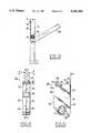
- FIG. 1is a partially schematic front view of a preferred embodiment of a curl spring balance system applied to a window sash.
- FIG. 2is a fragmentary schematic front view of the balance system of FIG. 1 showing a raised and tilted sash.
- FIG. 3is a partially schematic side view of the window of FIG. 2 showing the balance system cooperating with a tilted sash.
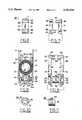
- FIG. 4is an edge view of a preferred embodiment of sash shoe for the inventive sash balance system.
- FIG. 5is a side view of the sash shoe of FIG. 4.
- FIG. 6is a top view of the sash shoe of FIGS. 4 and 5, taken along the line 6--6 of FIG. 4.
- FIG. 7is a top view of the sash shoe of FIG. 6 with shoe body parts separated and aligned for interconnection.
- FIG. 8is a side view of the sash shoe of FIG. 4, with one body half removed from along the line 8--8 thereof.
- FIG. 9is a partially cutaway side view of the sash shoe of FIG. 7 with separated body parts aligned for closing together on a pin receiver and locking cam.
- FIG. 10is a front view of a preferred embodiment of pin receiver and locking cam for the inventive sash shoe.
- FIG. 11is side view of the receiver and locking cam of FIG. 10.
- FIG. 12is a partially cutaway schematic edge view of a preferred embodiment of sash shoe locked in a shoe channel by means of a shoe locking cam.
- FIG. 13is a partially cutaway schematic edge view showing shoe body parts adjustably separated for shoe friction purposes.
- FIG. 14is a side view of a preferred embodiment of sash shoe combined with a mount for a curl spring.
- FIG. 15is a spring side edge view of the shoe of FIG. 14.
- FIG. 16is a partially schematic top view of a preferred mount of a curl spring in a shoe channel.
- FIG. 17is a side view of a preferred embodiment of a companion carrier for a companion curl spring usable in the inventive balance system.
- FIG. 18is a spring side edge view of the companion carrier of FIG. 17.
- FIG. 19is a side view of the companion carrier of FIG. 18, with a body half removed from along the line 19--19 thereof.
- FIG. 20is a side view of a preferred embodiment of shoe and companion carrier assembled with springs and a mount.
- FIG. 21is an edge view of the assembly of FIG. 20.
- FIG. 22is a partially schematic, elevational view of an alternative mount for a curl spring carried by a sash shoe.
- FIG. 23is a partially schematic, elevational view of alternative mounts for a pair of curl springs carried by a sash shoe.
- FIG. 24is a partially schematic, elevational view of a sash shoe having separable curl spring carriers.
- FIG. 25is a partially schematic, elevational view of an alternative shoe cavity mount for a curl spring.
- FIGS. 1-3schematically show a generally preferred arrangement for employing curl springs 10 within shoes 50 counterbalancing sash 20.
- Free end regions 11 of springs 10are fixed in positions within shoe channels 15, as schematically indicated by fastener 12.
- Curled up convolutions 13 of springs 10are contained within shoes 50, which move up and down in shoe channels 15 as sash 20 moves up and down in sash runs 16.
- Shoes 50are interconnected with sash 20, preferably by means of pivot bars or pins 63, which allow sash 20 to tilt, as shown in FIG. 3.
- Shoes 50preferably lock in shoe channels 15 when sash 20 tilts, but it is also possible to allow shoes 50 to rise in channels 15 from the upward bias of springs 10 when tilting of sash 20 removes some of the sash weight from shoes 50.
- the curl spring counterbalance arrangement schematically shown in FIGS. 1-3achieves the general advantages mentioned above.
- Measurements of currently marketed balance systems using curl springs mounted in jamb shoe channels so that free end regions of the curl springs connect to sash shoes movable in the shoe channelsshow that only about 30 to 40 percent of the potential spring force is actually delivered to lift the sash.
- the same measurements applied to the arrangement shown in FIGS. 1-3, with curled up spring convolutions 13 contained within movable sash shoes 50show that 67 percent of the potential spring force was delivered to lift sash 20.
- the substantial efficiency improvement achieved by the illustrated arrangementcomes from eliminating the friction of sliding an uncurled length of spring against the shoe channel surface.
- This frictional lossis surprisingly large because of the tendency of spring 10 to curl so that its uncurled length bends and presses against a fixed channel surface as the spring moves.
- the pressure of spring 10 against a wall of shoe channel 15does not cause any frictional loss, because the uncurled length of spring 10 does not move relative to shoe channel 15.
- spring 10rests flat and motionless against shoe channel wall 15 as spring 10 recurls into coiled convolutions 13 when shoes 50 and sash 20 rise and uncurls from shoes 50 into shoe channel 15 when shoes 50 and sash 20 move downward.
- curl springs 10in the balance system illustrated in FIGS. 1-3 allows larger lifting forces to be derived from curl springs of the same width and curl diameter so that sash lifting force can be increased within the size and shape limitations for the springs. Also, making the spring arrangement more efficient can be used to extend the spring cycle life.
- the coiling radius and spring thicknesscan result in a short cycle life if a spring filling the available space is designed for a maximum lifting force necessary to overcome excessive friction. When the friction is greatly reduced, making the spring employment more efficient, a spring fitting within the same space can be designed for a longer cycle life while still providing adequate lift.
- the spring force of curl springsis generally proportional to spring width, and limits on the size and configuration of space within window jambs also limit the width that can be used for curl springs. These are usually constant force springs and are often referred to as constant force springs; but it is possible to vary the spring force along its length, by changing the width, the curling radius, or the temper of the spring steel. Some friction is unavoidably involved in the curling and uncurling of convolutions of the springs within a containment region, but this can be minimized by selection of low friction bearings or materials disposed in the spring coiling region.
- Another advantage of the illustrated arrangementis elimination of the sliding noise of a metal spring rubbing along a shoe channel surface. Without this noise, sash operation is much quieter and gives a person moving the sash a sense of precision and refinement.
- Containment of curled up spring convolutions 13 in shoes 50also better accommodates the balance springs to the vertical travel desired for sash 20.
- Free end region 11 of spring 10can be secured in shoe channel 15 above the uppermost limit of travel of shoes 50 with sash 20. This level can be above the upper rail of sash 20, as shown in FIG. 1; because a tilt latch, which is commonly arranged at the upper rail of a tilt sash but is not illustrated in the drawings, can move up and down over the mounting of free end region 11 without interference.
- convolutions of curl springs 13are mounted in shoe channels, as suggested in the prior art, these interfere with a tilt latch at the top rail of sash 20 so that they have to be mounted below the lowermost travel of the top rail of sash 20.
- FIGS. 4-11A preferred embodiment of lock shoe 50 is illustrated in FIGS. 4-11.
- Shoe 50is formed of two identical parts or halves 51 so that any one of the parts 51 can join with any other part 51 to form a complete body for shoe 50.
- Each body part 51is formed to provide half of a containment region 53 for receiving the curled up convolutions 13 of spring 10.
- Each body part 51also provides half of an opening 52 for a pin or pivot bar receiver 60.
- Opposite lower sides 54 of body parts 51are parallel and separated by a suitable distance for a smooth sliding fit in shoe channel 15, and upper sides 55 of body parts 51 are separated by a smaller distance to allow a length of spring 10 to pass from containment region 53 in between one of the shoe side walls 55 and a wall of shoe channel 15.
- a pair of openings 56are formed between lower walls 54 and upper walls 55 to allow passage of an uncurled length of spring 10. This allows spring 10 to uncurl from either side of containment region 53, and it also allows body parts 51 to be made identical and have registered openings 56 when assembled together. Assembling shoe 50 from a pair of identical body parts 51 also gives shoe 50 identical front and rear faces so that the shoe can be installed with either face confronting sash 20.
- a projection 57 and a recess 58are formed at the top of each body part 51 so that the downward facing portion 59 of each projection 57 can be slid into recess 58 of a confronting body part as shown in FIG. 8.
- the downward facing portions of projections 59have interference fits in slots 58 and thus hold body parts 51 in the assembled relation of FIGS. 4 and 6.
- curled spring convolutions 13are placed in containment region 53 so that spring 10 extends out of an opening 56, and receiver 60 is positioned in opening 52 between the body parts.
- Receiver 60has a preferably cylindrical body 61 with a through opening 62 that receives a pin or pivot bar 63 connected to sash 20. Receiver 60 thus participates in a connection between shoe 50 and sash 20, and many variations of such a connection are possible.
- a platform or other supportcan extend from shoe 50 to sash 20, for example.
- Window jambsnormally include a slot between a sash run 16 and a shoe channel 15 allowing a connector such as pin 63 to extend between shoe 50 and sash 20.
- Receiver 60preferably includes a cam 65 formed as an annular sector extending part way around cylindrical body 61.
- Cam 65fits within a recess 45 in each of the body parts 51, and inclined cam follower surfaces 46 connect recess 45 with a confronting face surface 47 of each body part 51.
- cam surface 65is positioned in recess 45, in the neutral or sash vertical position for receiver 60, confronting surfaces 47 of body parts 51 are closed or engaged.
- receiver 60is turned or pivoted within shoe 50, which makes cam 65 ride up one of the inclined surfaces 46 onto face surface 47. This spreads body parts 51 apart by the thickness of cam 65. It also allows cam 65 to pivot in either direction to accomplish the cammed separation of body parts 51, as shown in FIG. 12.
- This thickens or widens shoe 50by increasing the separation between its front and back surfaces so that shoe 50 locks in shoe channel 15 when sash 20 tilts.
- the amount of shoe wideningis determined by the thickness of cam 65, which can be varied to meet different shoe locking requirements.
- the top of shoe 50which is held together by projections 59 in recesses 58, remains tightly assembled, and shoe body parts 51 flex to allow the cammed separation of their lower regions when the shoe locks.
- the spreading of shoe 50occurs in a direction parallel with sash 20, which extends across the narrower of the generally rectangular dimensions of shoe channel 15; and this may account for the improved locking force provided by cam 65 disposed between face surfaces 47.
- Shoe 50can also be provided with adjustable friction, although there is less need for friction adjustment in curl spring balance systems because of the normally constant force of the curl springs. If the spring lift is a little excessive, though, or if the upper sash has a tendency to drop from an uppermost position, the frictional fit of shoe 50 in shoe channel 15 can be increased. This is preferably done by means of an opening 44 formed eccentrically into an upper region of body parts 51 so that openings 44 in a pair of assembled body parts do not register with each other. Then, a screw 43 can be threaded into an opening 44 in one of the body parts 51, and its leading end will engage a confronting surface of the mating body part. Further turning of the screw will urge the upper regions of body parts 51 apart, as shown in FIG. 13, to thicken shoe 50 enough to increase its frictional resistance to movement in channel 15.
- curl springs 10 in sash shoes 50affords not only a simple and efficient sash shoe, but a simple and efficient way of combining a spring mount and a sash shoe, as shown in FIGS. 14-16.
- Some sort of fastener or mountis preferred for fastening free end region 11 of spring 10 in shoe channel 15, and the invention provides such a mount 70 arranged to cooperate with spring 10 and shoe 50 to form a secure subassembly that simplifies the installation of the spring and shoe.
- projections 57are formed to extend upward from the top of shoe 50 to serve at least two purposes. One of these purposes is to engage and hold mount 70 on top of shoe 50 in an engagement with free end region 11 of spring 10, as shown in FIG. 14.
- the upward facing regions of projections 57have dovetailed or enlarged heads 67, and mount 70 has an end projection 71 that hooks under one of the projections 67 while the opposite end of mount 70 has a hook 72 and a guide 73 that engage respective openings 74 and 75 in free end region 11 of spring 10. Hook 72 holds spring 10 against any downward movement, and guide 73 keeps mount 70 oriented upright in alignment with the lineal direction of spring 10.
- mount 70rests on one of the heads 67 of the projections 57, hooks under the other head 67 of the other projection 57, and engages the free end region 11 of spring 10.
- the recoil tendency of spring 10pulls mount 70 downward against the top of shoe 50 in the position shown in FIG. 14, and the engagement of hook 72 and guide 73 with openings 74 and 75 in spring 10 keeps mount 70 from tilting or escaping from the illustrated position.
- Thisreliably holds mount 70 on top of shoe 50 in a preliminary subassembly that is ready for installation, with mount 70 hooked into the free end region 11 of spring 10.
- the illustrated subassemblykeeps mount 70 from being separated or lost and avoids the problems otherwise involved in assembling and organizing several independent components at the moment of installation.
- the inventionalso allows mount 70 to release automatically from its preassembly position on top of shoe 50, when mount 70 is secured within shoe channel 15 by a fastener 12, as illustrated in FIG. 16.
- the upward facing heads 67 of projections 57are formed with mount release slots 68 that release projection 71 from its trapped position under one of the heads 67, when fastener 12 is driven through hole 76 in mount 70 and into a wall of shoe channel 15.
- mount 70is pressed against the shoe channel wall in the region of fastener 12
- its projection 71is moved to a face region of shoe 50 where one of the release slots 68 allows projection 71 to escape from its hooked position under projection head 67.
- mount 70 in place in shoe channel 15also bends mount 70 between the region of fastener hole 76 and hook 72, which remains engaged with opening 74 in the free end region 11 of spring 10. This does not impair the ability of mount 70 to hold spring 10 securely in place in a mounted position in shoe channel 15, though.
- mount 70releasably on the top of shoe 50 has several advantages. It not only forms a preassembly package of spring 10, shoe 50, and mount 70 that can be shipped as a subassembly to a window manufacturer, but it positions these components so that installation involves only positioning shoe 50 to dispose mount 70 at the proper elevation in shoe channel 15 and then driving fastener or screw 12 through hole 76. As screw 12 forces mount 70 against a wall of shoe channel 15, mount 70 automatically releases from its preassembly position on top of shoe 50. This happens without loss of engagement between mount 70 and the free end region 11 of spring 10 so that spring 10 is properly mounted in the shoe channel by the simple act of driving a fastener through hole 76 in mount 70.
- shoe 50spring 10, and mount 70 also allows installation of shoe 50 in either of its two possible orientations in shoe channel 15. This means that any shoe can function on the right or left sides of a sash, and any shoe can be mounted to position spring 10 on the preferred side of shoe channel 15. This is normally on the inside surface of shoe channel 15, where spring 10 is not visible to a person operating sash 20 from inside a building.
- the installed arrangement of the preferred embodiment of shoe 50disposes the curled convolutions 13 of spring 10 on an axis parallel with sash 20 and its tilt axis on pins 63. It is also possible to turn the axis of curled convolutions 13 by 90 degrees, providing shoe channel 15 can be made deep enough to accommodate such a spring orientation. This can occur in large "architectural" windows having window jambs of considerable depth. If such an orientation of springs 10 is used, a different form of mount would be desirable.
- the inventionalso facilitates ganging the springs in tandem. This involves forming a sash shoe with more than one containment region for the curled convolutions 13 of curl springs 10; and from among the several ways this can be done, a preferred way is illustrated in FIGS. 17-21.
- a companion curl spring 25 having curled up spring convolutions 23 and a free end region 21is arranged in a containment region 33 of a companion carrier 30 that can be interconnected to an upper region of shoe 50, as illustrated.
- companion carrier 30allows additional curl spring 25 to be added to spring 10 in shoe 50, whenever the additional lifting force of an extra spring is required, without forming a sometimes unnecessary additional spring containment region within shoe 50 itself.
- the projections 57with their heads 67, extending above the top of shoe 50 as previously described, serve as interconnectors for companion carrier 30, which has recesses 38 formed in its bottom region to provide a sliding interlock fit with projections 57.
- the body of companion or piggyback carrier 30is preferably formed of two identical parts 31.
- the upper region of each part 31is formed with the same projection 57 and recess 58 as is formed on the top region of shoe body part 51.
- the halves 31 of companion carrier 30confront and slide together in an interlocked fit of projections 59 in recesses 58 in the same way as described for the locking together of shoe body parts 51.
- Openings 36are formed on each side of containment region 33 so that companion spring 25 can extend through either opening 36 in the same way that spring 10 extends through either opening 56 of shoe 50.
- mount 70When companion case 30 is desired for increasing the lifting force by adding companion spring 25, then mount 70 has its hook 72 and guide 73 interconnected with openings 74 and 75 formed in free end regions 21 and 11 of the combined springs so that mount 70 can be preassembled with the springs on top of companion case 30 in the same way that mount 70 can be preassembled on the top of shoe 50.
- Thisis made possible by the presence of projections 57 with their enlarged heads 67 formed on the top of companion carrier 30 in the same way they are formed on the top of shoe 50.
- Projections 57also enable two or more companion carriers 30 to be piggybacked or stacked on top of shoe 50 so that three, four, or more springs can provide a combined lift. This may require elevating the mounting position of the free end regions of the multiple springs; but since the preferred spring mount 70 does not interfere with sash movement, this becomes possible by using suitable lengths for the springs involved.
- FIGS. 4-21all involve cavity mounts for the curled up convolutions of a curl spring, and all arrange at least one cavity for a curl spring within the sash shoe. It is also possible for the curl spring mount to be arranged outboard of a sash shoe and for curled up convolutions of a curl spring to be mounted on a hub or bushing, instead of confined within a cavity. Several of these possibilities are schematically illustrated in FIGS. 22-25.
- the sash shoe 80 of FIG. 22includes a receiver 60 affording a connection with a sash and is configured for running in a shoe channel. It also carries the curled up convolutions 13 of curl spring 10, but does so in an outboard mount, rather than an inboard mount. This is formed by hub 81 arranged above shoe 80 to hold curled up convolutions 13. Hub 81 can be fixed to shoe 80 or removably attached to shoe 80 and can also be arranged within a cavity provided within a sash shoe. Curl spring 10 curls up onto hub 81 and uncurls from hub 81 as shoe 80 moves up and down.
- hub 81can be mounted to rotate on a journal or bearing 82, as schematically shown in FIG. 23.
- Bearing 82, rotationally supporting hub 81,is connected to shoe 80 by a link 83 that can be either fixed or removable.
- a rotatable hub 81can also be arranged within a sash shoe.
- a tandem outboard mount of curl springsis also possible, as shown in FIG. 23.
- a companion hub 81 supporting curled convolutions 23 of a companion curl spring 25can be added to shoe 80 by extending link 83 to a companion bearing 82.
- Springs 10 and 25are shown extending upward above opposite sides of shoe 80, to illustrate this possibility.
- Another shoe 85has one or a plurality of curl springs detachably connected to the body of shoe 85.
- Dovetails 86are arranged in a manner similar to the arrangement of projections 57 so that curl spring containers 87 and 88 can be mounted as desired on top of shoe 85.
- the curled up convolutions 89 of curl springs 90are contained within carriers 87 and 88, they can be mounted on rotatable hubs 91, instead of being cavity mounted.
- a cavity mountcan reduce the friction of curling and uncurling a spring by providing friction bearings 92, as shown in FIG. 25. These can engage the outermost of the curled convolutions 13 of spring 10 in shoe 93.
- FIGS. 22-25are independently combinable with features of the embodiments of FIGS. 4-21. Instead of representing distinct species, the features shown in FIGS. 22-25 illustrate alternatives that can be combined in many specifically different ways.
Landscapes
- Engineering & Computer Science (AREA)
- Mechanical Engineering (AREA)
- Closing And Opening Devices For Wings, And Checks For Wings (AREA)
- Holders For Apparel And Elements Relating To Apparel (AREA)
- Window Of Vehicle (AREA)
Abstract
Description
Claims (63)
Priority Applications (4)
| Application Number | Priority Date | Filing Date | Title |
|---|---|---|---|
| US08040457US5353548B1 (en) | 1993-04-01 | 1993-04-01 | Curl spring shoe based window balance system |
| CA002119506ACA2119506C (en) | 1993-04-01 | 1994-03-21 | Curl spring shoe based window balance system |
| GB9406149AGB2276655B (en) | 1993-04-01 | 1994-03-29 | Sash window balance system |
| US08280491US5463793B1 (en) | 1993-04-01 | 1994-07-26 | Sash shoe system for curl spring window balance |
Applications Claiming Priority (1)
| Application Number | Priority Date | Filing Date | Title |
|---|---|---|---|
| US08040457US5353548B1 (en) | 1993-04-01 | 1993-04-01 | Curl spring shoe based window balance system |
Related Child Applications (1)
| Application Number | Title | Priority Date | Filing Date |
|---|---|---|---|
| US08280491DivisionUS5463793B1 (en) | 1993-04-01 | 1994-07-26 | Sash shoe system for curl spring window balance |
Publications (2)
| Publication Number | Publication Date |
|---|---|
| US5353548Atrue US5353548A (en) | 1994-10-11 |
| US5353548B1 US5353548B1 (en) | 1997-04-08 |
Family
ID=21911080
Family Applications (2)
| Application Number | Title | Priority Date | Filing Date |
|---|---|---|---|
| US08040457Expired - LifetimeUS5353548B1 (en) | 1993-04-01 | 1993-04-01 | Curl spring shoe based window balance system |
| US08280491Expired - LifetimeUS5463793B1 (en) | 1993-04-01 | 1994-07-26 | Sash shoe system for curl spring window balance |
Family Applications After (1)
| Application Number | Title | Priority Date | Filing Date |
|---|---|---|---|
| US08280491Expired - LifetimeUS5463793B1 (en) | 1993-04-01 | 1994-07-26 | Sash shoe system for curl spring window balance |
Country Status (3)
| Country | Link |
|---|---|
| US (2) | US5353548B1 (en) |
| CA (1) | CA2119506C (en) |
| GB (1) | GB2276655B (en) |
Cited By (64)
| Publication number | Priority date | Publication date | Assignee | Title |
|---|---|---|---|---|
| US5513469A (en)* | 1995-02-27 | 1996-05-07 | Tajudeen; Eddie R. | Retractable sliding door |
| US5661927A (en)* | 1996-03-06 | 1997-09-02 | Ashland Products, Inc. | Sliding counterbalance assembly for a sash window |
| US5924243A (en)* | 1997-01-08 | 1999-07-20 | Ashland Products, Inc. | Rotor for a sash balance brake and pivot pin assembly |
| US6032417A (en)* | 1997-04-11 | 2000-03-07 | Caldwell Manufacturing Company | Corner locking carrier shoe for tilt sash |
| US6047762A (en)* | 1998-03-20 | 2000-04-11 | Prince Corporation | Shade control for a vehicle window |
| US6378169B1 (en) | 2000-04-07 | 2002-04-30 | Caldwell Manufacturing Company | Mounting arrangement for constant force spring balance |
| USD462258S1 (en) | 2000-11-13 | 2002-09-03 | Amesbury Group, Inc. | Double coil window balance |
| USD464256S1 (en) | 2000-11-13 | 2002-10-15 | Amesbury Group, Inc. | Single coil window balance |
| US6523307B2 (en) | 2000-04-19 | 2003-02-25 | Ashland Products, Inc. | Balance system for sash window assembly |
| US20030074764A1 (en)* | 2001-10-23 | 2003-04-24 | Dean Pettit | Block and tackle sash balance brake assembly |
| US6553620B2 (en)* | 2001-02-09 | 2003-04-29 | Ferco Architectural Hardware | Balancing spring system for sliding window sash |
| US6606761B2 (en)* | 2001-02-05 | 2003-08-19 | Omega International Ltd | Spring mounting arrangement for a sash window counterbalance arrangement |
| US6622342B1 (en) | 2001-06-06 | 2003-09-23 | Ashland Products, Inc. | Block and tackle balance assembly with brake shoe |
| US20040036300A1 (en)* | 2001-04-05 | 2004-02-26 | 420820 Ontario Limited | Combination cam lock/tilt latch and latching block therefor with added security feature |
| WO2004057140A1 (en)* | 2002-12-19 | 2004-07-08 | Clearview Industries Limited | A modular spring mounting for a sash window counterbalance arrangement |
| US6802105B2 (en) | 2002-07-12 | 2004-10-12 | Ashland Products, Inc. | Spring balance assembly |
| US20040206001A1 (en)* | 2003-04-18 | 2004-10-21 | Kunz John R. | Shoeless curl spring counterbalance system for a tilt-in window |
| US20040206002A1 (en)* | 2003-04-18 | 2004-10-21 | Kunz John R. | Counterbalance system for a tilt-in window |
| US20040216380A1 (en)* | 2001-01-12 | 2004-11-04 | Amesbury Group, Inc. | Snap lock balance shoe and system for a pivotable window |
| US20040237256A1 (en)* | 2003-05-30 | 2004-12-02 | Lutfallah Anthony G. | Block and tackle balance assembly with brake shoe |
| US6848148B2 (en) | 2000-11-09 | 2005-02-01 | Amesbury Springs Limited | Spring mounting for sash window tensioning arrangements |
| US20050091791A1 (en)* | 2003-11-05 | 2005-05-05 | Kunz John R. | Counterbalance system for a tilt-in window having an improved shoe assembly and anchor mount |
| US20050132653A1 (en)* | 2003-12-17 | 2005-06-23 | Lundahl Dave B. | Multi-coil spring window counterbalance assembly |
| US20050160676A1 (en)* | 2003-02-20 | 2005-07-28 | Dean Pettit | Spring balance assembly |
| US20050198775A1 (en)* | 2004-02-27 | 2005-09-15 | Dean Pettit | Spring balance assembly |
| US20060021283A1 (en)* | 2004-07-01 | 2006-02-02 | Schultz Steven E | Spring balance assembly |
| US20060112642A1 (en)* | 2004-11-30 | 2006-06-01 | Mike Derham | Spring balance adjustment |
| US20060172200A1 (en)* | 2005-02-03 | 2006-08-03 | Jae-Gu Yoon | Organic electrolytic solution and lithium battery employing the same |
| US20060230682A1 (en)* | 2005-04-14 | 2006-10-19 | S.I.L. Plastic Sales & Supplies Inc. | Sliding shoe for a window frame |
| US20070101654A1 (en)* | 2005-10-25 | 2007-05-10 | Caldwell Manufacturing Company | Spring Wiper for Curl Spring Balances |
| US20080120804A1 (en)* | 2006-09-18 | 2008-05-29 | Annes Jason L | Spring balance assembly |
| US20080178424A1 (en)* | 2007-01-29 | 2008-07-31 | Caldwell Manufacturing Company | Locking Shoe Formed in Non-rotatable Halves for Curl Spring Window Balance System |
| US20080178425A1 (en)* | 2007-01-29 | 2008-07-31 | Caldwell Manufacturing Company | Locking Shoe and Mounting Bracket for Curl Spring Window Balance System |
| US20090183432A1 (en)* | 2005-03-24 | 2009-07-23 | Lundahl Dave B | Hook and loop weatherstripping system |
| US20090205257A1 (en)* | 2008-02-20 | 2009-08-20 | Kurt Winner | Resistant tilt-in windows |
| US20090260295A1 (en)* | 2008-04-21 | 2009-10-22 | Caldwell Manufacturing Company | Frictional Drop Resistance for Sash Counterbalanced by Curl Springs |
| US20090277097A1 (en)* | 2008-05-07 | 2009-11-12 | Caldwell Manufacturing Company | Dynamic Window Jamb Channel Block |
| US7966770B1 (en) | 2005-03-07 | 2011-06-28 | Kunz John R | Rounded shoe and position brake assembly for the counterbalance system of a tilt-in window |
| US7980028B1 (en)* | 2007-07-16 | 2011-07-19 | Kunz John R | Coil spring counterbalance system for side loading window sashes |
| US8371068B1 (en) | 2005-03-07 | 2013-02-12 | John R. Kunz | System and method for improving the wear life of a brake shoe in the counterbalance system of a tilt-in window |
| US8464466B1 (en)* | 2010-12-27 | 2013-06-18 | John R. Kunz | Window having a counterbalance system that maximizes egress opening |
| US8505242B1 (en)* | 2007-07-16 | 2013-08-13 | John R. Kunz | Counter balance system for a window having side loading sashes |
| US8561260B2 (en) | 2010-02-09 | 2013-10-22 | Caldwell Manufacturing Company North America, LLC | Window balance assembly |
| US20140013669A1 (en)* | 2012-07-10 | 2014-01-16 | Caldwell Manufacturing Company North America, LLC | Tilt sash counterbalance system including curl spring mount stabilizer |
| US20140208653A1 (en)* | 2013-01-31 | 2014-07-31 | Caldwell Manufacturing Company North America, LLC | Carrier device for window balance assembly |
| US8819896B2 (en) | 2010-02-09 | 2014-09-02 | Caldwell Manufacturing Company North America, LLC | Locking carrier and mounting arrangement for tilt sash counterbalance systems |
| US20140259524A1 (en)* | 2013-03-14 | 2014-09-18 | Caldwell Manufacturing Company North America, LLC | Modular window balance assembly |
| US8850745B2 (en) | 2012-06-28 | 2014-10-07 | Caldwell Manufacturing Company North America, LLC | Window counterbalance system and mounting bracket therefor |
| US20150167379A1 (en)* | 2012-08-10 | 2015-06-18 | Caldwell Manufacturing Company North America, LLC | Air And Debris Dam For Moving Coil Balance Assembly |
| US20150240559A1 (en)* | 2014-02-27 | 2015-08-27 | Nien Made Enterprise Co., Ltd. | Window blind with carriage |
| US9133656B2 (en) | 2010-04-06 | 2015-09-15 | Amesbury Group, Inc. | Inverted constant force window balance for tilt sash |
| US20160138330A1 (en)* | 2014-11-18 | 2016-05-19 | Ya-Ling Huang | Cord-winding device for a blind assembly having no pull cord |
| US9371677B1 (en) | 2012-10-18 | 2016-06-21 | John Evans' Sons, Inc. | Brake shoe with contact posts that increase brake strength and improve the interconnection between the brake shoe and a counterbalance spring of a tilt-in window |
| US9458655B2 (en) | 2014-11-17 | 2016-10-04 | Caldwell Manufacturing Company North America, LLC | Constant force moving coil window balance with drop-in carrier |
| US20170145722A1 (en)* | 2015-11-20 | 2017-05-25 | Amesbury Group, Inc. | Constant force window balance engagement system |
| US10081972B1 (en) | 2017-08-16 | 2018-09-25 | John Evans' Sons, Inc. | Versatile and economic anchor mount for a coil spring in a window counterbalance assembly |
| US10208517B2 (en)* | 2016-04-12 | 2019-02-19 | Caldwell Manufacturing Company North America, LLC | Window balance assembly including sash support bracket |
| CN110719984A (en)* | 2017-04-07 | 2020-01-21 | 埃美斯博瑞集团有限公司 | Inverted Constant Force Window Balancing System |
| US10711517B2 (en) | 2015-01-21 | 2020-07-14 | Nien Made Enterprise Co., Ltd. | Lifting device of cordless covering |
| US11193318B2 (en) | 2017-09-21 | 2021-12-07 | Amesbury Group, Inc. | Window balance shoes for a pivotable window |
| US11352821B2 (en) | 2019-01-09 | 2022-06-07 | Amesbury Group, Inc. | Inverted constant force window balance having slidable coil housing |
| US11549293B1 (en)* | 2019-11-12 | 2023-01-10 | Barry G. Lawrence | Threaded pivot bar and method |
| US11560743B2 (en) | 2019-04-02 | 2023-01-24 | Amesbury Group, Inc. | Window balance systems |
| US12168899B2 (en) | 2021-09-08 | 2024-12-17 | Assa Abloy Fenestration, Llc | Window balance assembly and mounting bracket therefor |
Families Citing this family (6)
| Publication number | Priority date | Publication date | Assignee | Title |
|---|---|---|---|---|
| GB9415824D0 (en)* | 1994-08-05 | 1994-09-28 | Caradon Catnic Ltd | Apparatus for mounting a sash in a frame |
| GB2292168B (en)* | 1994-08-05 | 1998-04-22 | Caradon Catnic Ltd | Apparatus for mounting a sash in a frame |
| CA2323280A1 (en) | 1999-12-13 | 2001-06-13 | Roy A. Thompson | A window panel balance apparatus and method |
| US7210267B2 (en)* | 2004-02-09 | 2007-05-01 | Amesbury Group, Inc. | Non-takeout lock for a pivot pin of tilt-type windows |
| US20050196249A1 (en)* | 2004-03-03 | 2005-09-08 | Ting-Tsai Huang | Hinge fastening apparatus |
| US20050193631A1 (en)* | 2004-03-08 | 2005-09-08 | Gary Marshik | Balance shoe for tilt-in window sashes |
Citations (22)
| Publication number | Priority date | Publication date | Assignee | Title |
|---|---|---|---|---|
| US2609193A (en)* | 1947-04-30 | 1952-09-02 | Eastern Metals Res Co Inc | Spring sash counterbalance |
| US2635282A (en)* | 1950-10-02 | 1953-04-21 | Sr Earl M Trammell | Spring counterbalance |
| US2684499A (en)* | 1950-12-05 | 1954-07-27 | Pullman Mfg Corp | Sash balance |
| US2732594A (en)* | 1956-01-31 | Double hung window sash | ||
| US2739344A (en)* | 1953-09-03 | 1956-03-27 | Grand Rapids Hardware Company | Window balance |
| US2817872A (en)* | 1955-12-15 | 1957-12-31 | Edwin E Foster | Window sash balance |
| US2873472A (en)* | 1955-06-03 | 1959-02-17 | Edwin E Foster | Spring sash balance |
| US3150420A (en)* | 1962-12-10 | 1964-09-29 | Brenner Al | Spring wiping device for windows |
| US3445964A (en)* | 1967-10-17 | 1969-05-27 | Edwin E Foster | Tilt-in window sash |
| US3452480A (en)* | 1967-09-14 | 1969-07-01 | Edwin E Foster | Spring sash counterbalance |
| US3475865A (en)* | 1968-02-29 | 1969-11-04 | Lyle L Arnes | Window counter-balancing construction |
| US3820193A (en)* | 1972-08-24 | 1974-06-28 | E Foster | Spring sash counterbalance |
| US3869754A (en)* | 1972-08-24 | 1975-03-11 | Edwin E Foster | Bracket for a spring sash counterbalance |
| US3992751A (en)* | 1975-06-23 | 1976-11-23 | Foster Edwin E | Spring sash counterbalance |
| US4227345A (en)* | 1979-01-26 | 1980-10-14 | Durham Jr Robert C | Tilt-lock slide for window sash |
| US4935987A (en)* | 1989-06-02 | 1990-06-26 | Product Design & Development, Inc. | Self-contained heavy duty constant force sliding sash counterbalance assembly |
| US4953258A (en)* | 1989-07-10 | 1990-09-04 | Metal Industries, Inc. | Balancing arrangement for double hung windows |
| US4961247A (en)* | 1989-12-07 | 1990-10-09 | Metal Industries, Inc. | Balancing arrangement for double hung windows |
| US5119591A (en)* | 1991-07-22 | 1992-06-09 | Product Design & Development, Inc. | Vertically slidable window unit |
| US5157808A (en)* | 1992-02-18 | 1992-10-27 | Product Design & Development, Inc. | Coil spring counterbalance hardware assembly and connection method therefor |
| US5210976A (en)* | 1991-08-16 | 1993-05-18 | Vinyl Concepts Incorporated | Window balance assembly |
| US5232208A (en)* | 1991-05-15 | 1993-08-03 | Braid Harold K | Springs for sash frame tensioning arrangements |
Family Cites Families (3)
| Publication number | Priority date | Publication date | Assignee | Title |
|---|---|---|---|---|
| US2644193A (en)* | 1950-11-17 | 1953-07-07 | Axel W Anderberg | Spring sash balance |
| US4089085A (en)* | 1977-03-28 | 1978-05-16 | Balance Systems, Inc. | Sash balances and components thereof |
| GB2286418B (en)* | 1991-02-07 | 1995-10-11 | Lb Plastics Ltd | Balance mechanisms for sliding sash windows |
- 1993
- 1993-04-01USUS08040457patent/US5353548B1/ennot_activeExpired - Lifetime
- 1994
- 1994-03-21CACA002119506Apatent/CA2119506C/ennot_activeExpired - Lifetime
- 1994-03-29GBGB9406149Apatent/GB2276655B/ennot_activeExpired - Fee Related
- 1994-07-26USUS08280491patent/US5463793B1/ennot_activeExpired - Lifetime
Patent Citations (22)
| Publication number | Priority date | Publication date | Assignee | Title |
|---|---|---|---|---|
| US2732594A (en)* | 1956-01-31 | Double hung window sash | ||
| US2609193A (en)* | 1947-04-30 | 1952-09-02 | Eastern Metals Res Co Inc | Spring sash counterbalance |
| US2635282A (en)* | 1950-10-02 | 1953-04-21 | Sr Earl M Trammell | Spring counterbalance |
| US2684499A (en)* | 1950-12-05 | 1954-07-27 | Pullman Mfg Corp | Sash balance |
| US2739344A (en)* | 1953-09-03 | 1956-03-27 | Grand Rapids Hardware Company | Window balance |
| US2873472A (en)* | 1955-06-03 | 1959-02-17 | Edwin E Foster | Spring sash balance |
| US2817872A (en)* | 1955-12-15 | 1957-12-31 | Edwin E Foster | Window sash balance |
| US3150420A (en)* | 1962-12-10 | 1964-09-29 | Brenner Al | Spring wiping device for windows |
| US3452480A (en)* | 1967-09-14 | 1969-07-01 | Edwin E Foster | Spring sash counterbalance |
| US3445964A (en)* | 1967-10-17 | 1969-05-27 | Edwin E Foster | Tilt-in window sash |
| US3475865A (en)* | 1968-02-29 | 1969-11-04 | Lyle L Arnes | Window counter-balancing construction |
| US3820193A (en)* | 1972-08-24 | 1974-06-28 | E Foster | Spring sash counterbalance |
| US3869754A (en)* | 1972-08-24 | 1975-03-11 | Edwin E Foster | Bracket for a spring sash counterbalance |
| US3992751A (en)* | 1975-06-23 | 1976-11-23 | Foster Edwin E | Spring sash counterbalance |
| US4227345A (en)* | 1979-01-26 | 1980-10-14 | Durham Jr Robert C | Tilt-lock slide for window sash |
| US4935987A (en)* | 1989-06-02 | 1990-06-26 | Product Design & Development, Inc. | Self-contained heavy duty constant force sliding sash counterbalance assembly |
| US4953258A (en)* | 1989-07-10 | 1990-09-04 | Metal Industries, Inc. | Balancing arrangement for double hung windows |
| US4961247A (en)* | 1989-12-07 | 1990-10-09 | Metal Industries, Inc. | Balancing arrangement for double hung windows |
| US5232208A (en)* | 1991-05-15 | 1993-08-03 | Braid Harold K | Springs for sash frame tensioning arrangements |
| US5119591A (en)* | 1991-07-22 | 1992-06-09 | Product Design & Development, Inc. | Vertically slidable window unit |
| US5210976A (en)* | 1991-08-16 | 1993-05-18 | Vinyl Concepts Incorporated | Window balance assembly |
| US5157808A (en)* | 1992-02-18 | 1992-10-27 | Product Design & Development, Inc. | Coil spring counterbalance hardware assembly and connection method therefor |
Cited By (124)
| Publication number | Priority date | Publication date | Assignee | Title |
|---|---|---|---|---|
| US5513469A (en)* | 1995-02-27 | 1996-05-07 | Tajudeen; Eddie R. | Retractable sliding door |
| US5661927A (en)* | 1996-03-06 | 1997-09-02 | Ashland Products, Inc. | Sliding counterbalance assembly for a sash window |
| US5924243A (en)* | 1997-01-08 | 1999-07-20 | Ashland Products, Inc. | Rotor for a sash balance brake and pivot pin assembly |
| US6032417A (en)* | 1997-04-11 | 2000-03-07 | Caldwell Manufacturing Company | Corner locking carrier shoe for tilt sash |
| US6047762A (en)* | 1998-03-20 | 2000-04-11 | Prince Corporation | Shade control for a vehicle window |
| US6378169B1 (en) | 2000-04-07 | 2002-04-30 | Caldwell Manufacturing Company | Mounting arrangement for constant force spring balance |
| US6523307B2 (en) | 2000-04-19 | 2003-02-25 | Ashland Products, Inc. | Balance system for sash window assembly |
| US20040255518A1 (en)* | 2000-04-19 | 2004-12-23 | Ashland Products, Inc. | Balance system for sash window assembly |
| US7093349B2 (en) | 2000-04-19 | 2006-08-22 | Newell Operating Company | System for manufacturing sash window assemblies |
| US6751904B2 (en) | 2000-04-19 | 2004-06-22 | Ashland Products, Inc. | Balance system for sash window assembly |
| US20070011846A1 (en)* | 2000-11-09 | 2007-01-18 | Amesbury Springs Limited | Spring mounting for sash window tensioning arrangements |
| US7076835B2 (en)* | 2000-11-09 | 2006-07-18 | Amesbury Springs Limited | Spring mounting for sash window tensioning arrangements |
| US7552510B2 (en) | 2000-11-09 | 2009-06-30 | Amesbury Springs Limited | Spring mounting for sash window tensioning arrangements |
| US20050055802A1 (en)* | 2000-11-09 | 2005-03-17 | Amesbury Springs Limited | Spring mounting for sash window tensioning arrangements |
| US6848148B2 (en) | 2000-11-09 | 2005-02-01 | Amesbury Springs Limited | Spring mounting for sash window tensioning arrangements |
| USD464256S1 (en) | 2000-11-13 | 2002-10-15 | Amesbury Group, Inc. | Single coil window balance |
| USD462258S1 (en) | 2000-11-13 | 2002-09-03 | Amesbury Group, Inc. | Double coil window balance |
| US6931788B2 (en) | 2001-01-12 | 2005-08-23 | Amesbury Group, Inc. | Locking balance shoe and system for a pivotable window |
| US9580950B2 (en) | 2001-01-12 | 2017-02-28 | Amesbury Group, Inc. | Locking balance shoe and system for a pivotable window |
| US20040216380A1 (en)* | 2001-01-12 | 2004-11-04 | Amesbury Group, Inc. | Snap lock balance shoe and system for a pivotable window |
| US6820368B2 (en) | 2001-01-12 | 2004-11-23 | Amesbury Group, Inc. | Snap lock balance shoe and system for a pivotable window |
| US20100115854A1 (en)* | 2001-01-12 | 2010-05-13 | Amesbury Group | Snap Lock Balance Shoe and System for a Pivotable Window |
| US7191562B2 (en) | 2001-01-12 | 2007-03-20 | Amesbury Group, Inc. | Locking balance shoe and system for a pivotable window |
| US20070113479A1 (en)* | 2001-01-12 | 2007-05-24 | Amesbury Group, Inc. | Snap lock balance shoe and system for a pivotable window |
| US8424248B2 (en) | 2001-01-12 | 2013-04-23 | Amesbury Group, Inc. | Method of installing a locking balance shoe and system for a pivotable window |
| US10344514B2 (en) | 2001-01-12 | 2019-07-09 | Amesbury Group, Inc. | Snap lock balance shoe and system for a pivotable window |
| US20050178068A1 (en)* | 2001-01-12 | 2005-08-18 | Amesbury Group, Inc. | Snap lock balance shoe and system for a pivotable window |
| US10533359B2 (en) | 2001-01-12 | 2020-01-14 | Amesbury Group, Inc. | Method of assembling a window balance system |
| US6606761B2 (en)* | 2001-02-05 | 2003-08-19 | Omega International Ltd | Spring mounting arrangement for a sash window counterbalance arrangement |
| US6553620B2 (en)* | 2001-02-09 | 2003-04-29 | Ferco Architectural Hardware | Balancing spring system for sliding window sash |
| US20040036300A1 (en)* | 2001-04-05 | 2004-02-26 | 420820 Ontario Limited | Combination cam lock/tilt latch and latching block therefor with added security feature |
| US7147255B2 (en)* | 2001-04-05 | 2006-12-12 | 420820 Ontario Limited | Combination cam lock/tilt latch and latching block therefor with added security feature |
| US20070094931A1 (en)* | 2001-06-06 | 2007-05-03 | Newell Operating Company | Block And Tackle Balance Assembly With Brake Shoe |
| US7143475B2 (en) | 2001-06-06 | 2006-12-05 | Newell Operating Company | Block and tackle balance assembly with brake shoe |
| US20030213096A1 (en)* | 2001-06-06 | 2003-11-20 | Jason Annes | Block and tackle balance assembly with brake shoe |
| US7673372B2 (en) | 2001-06-06 | 2010-03-09 | Newell Operating Company | Block and tackle balance assembly with brake shoe |
| US6622342B1 (en) | 2001-06-06 | 2003-09-23 | Ashland Products, Inc. | Block and tackle balance assembly with brake shoe |
| US20030074764A1 (en)* | 2001-10-23 | 2003-04-24 | Dean Pettit | Block and tackle sash balance brake assembly |
| US7013529B2 (en) | 2001-10-23 | 2006-03-21 | Newell Operating Company | Block and tackle sash balance brake assembly |
| US6802105B2 (en) | 2002-07-12 | 2004-10-12 | Ashland Products, Inc. | Spring balance assembly |
| WO2004057140A1 (en)* | 2002-12-19 | 2004-07-08 | Clearview Industries Limited | A modular spring mounting for a sash window counterbalance arrangement |
| US20060096178A1 (en)* | 2002-12-19 | 2006-05-11 | Clearview Industries Limited | Modular spring mounting for a sash window counterbalance arrangement |
| US7676989B2 (en)* | 2002-12-19 | 2010-03-16 | Clearview Industries Limited | Modular spring mounting for a sash window counterbalance arrangement |
| US6983513B2 (en) | 2003-02-20 | 2006-01-10 | Newell Operating Company | Spring balance assembly |
| US20050160676A1 (en)* | 2003-02-20 | 2005-07-28 | Dean Pettit | Spring balance assembly |
| US7587787B2 (en) | 2003-02-20 | 2009-09-15 | Newell Operating Company | Spring balance assembly |
| US20040206001A1 (en)* | 2003-04-18 | 2004-10-21 | Kunz John R. | Shoeless curl spring counterbalance system for a tilt-in window |
| US20040206002A1 (en)* | 2003-04-18 | 2004-10-21 | Kunz John R. | Counterbalance system for a tilt-in window |
| US6857228B2 (en)* | 2003-04-18 | 2005-02-22 | John Evans Sons, Inc | Counterbalance system for a tilt-in window |
| US6860066B2 (en) | 2003-04-18 | 2005-03-01 | John Evans Sons, Inc | Shoeless curl spring counterbalance system for a tilt-in window |
| WO2004104343A1 (en)* | 2003-05-16 | 2004-12-02 | John Evans Sons, Inc. | Counterbalance system for a tilt-in window |
| US20040237256A1 (en)* | 2003-05-30 | 2004-12-02 | Lutfallah Anthony G. | Block and tackle balance assembly with brake shoe |
| US6990710B2 (en)* | 2003-11-05 | 2006-01-31 | Kunz John R | Counterbalance system for a tilt-in window having an improved shoe assembly and anchor mount |
| US20050091791A1 (en)* | 2003-11-05 | 2005-05-05 | Kunz John R. | Counterbalance system for a tilt-in window having an improved shoe assembly and anchor mount |
| US20060200940A1 (en)* | 2003-12-17 | 2006-09-14 | Inovadeas, Llp | Multi-coil spring window counterbalance assembly |
| US7047693B2 (en)* | 2003-12-17 | 2006-05-23 | Inovadeas, Lllp | Multi-coil spring window counterbalance assembly |
| US20050132653A1 (en)* | 2003-12-17 | 2005-06-23 | Lundahl Dave B. | Multi-coil spring window counterbalance assembly |
| US20050198775A1 (en)* | 2004-02-27 | 2005-09-15 | Dean Pettit | Spring balance assembly |
| US20060021283A1 (en)* | 2004-07-01 | 2006-02-02 | Schultz Steven E | Spring balance assembly |
| US20060112642A1 (en)* | 2004-11-30 | 2006-06-01 | Mike Derham | Spring balance adjustment |
| US7093392B2 (en) | 2004-11-30 | 2006-08-22 | Mighton Products, Limited | Spring balance adjustment |
| US7410731B2 (en) | 2005-02-03 | 2008-08-12 | Samsung Sdi Co., Ltd. | Organic electrolytic solution and lithium battery employing the same |
| US20060172200A1 (en)* | 2005-02-03 | 2006-08-03 | Jae-Gu Yoon | Organic electrolytic solution and lithium battery employing the same |
| US7966770B1 (en) | 2005-03-07 | 2011-06-28 | Kunz John R | Rounded shoe and position brake assembly for the counterbalance system of a tilt-in window |
| US8371068B1 (en) | 2005-03-07 | 2013-02-12 | John R. Kunz | System and method for improving the wear life of a brake shoe in the counterbalance system of a tilt-in window |
| US20090183432A1 (en)* | 2005-03-24 | 2009-07-23 | Lundahl Dave B | Hook and loop weatherstripping system |
| US20060230682A1 (en)* | 2005-04-14 | 2006-10-19 | S.I.L. Plastic Sales & Supplies Inc. | Sliding shoe for a window frame |
| US7726073B2 (en)* | 2005-04-14 | 2010-06-01 | S.I.L. Plastic Sales & Supplies Inc. | Sliding shoe for a window frame |
| US20070101654A1 (en)* | 2005-10-25 | 2007-05-10 | Caldwell Manufacturing Company | Spring Wiper for Curl Spring Balances |
| US20080120804A1 (en)* | 2006-09-18 | 2008-05-29 | Annes Jason L | Spring balance assembly |
| US20080178424A1 (en)* | 2007-01-29 | 2008-07-31 | Caldwell Manufacturing Company | Locking Shoe Formed in Non-rotatable Halves for Curl Spring Window Balance System |
| US7735191B2 (en) | 2007-01-29 | 2010-06-15 | Caldwell Manufacturing Company | Locking shoe and mounting bracket for curl spring window balance system |
| US20080178425A1 (en)* | 2007-01-29 | 2008-07-31 | Caldwell Manufacturing Company | Locking Shoe and Mounting Bracket for Curl Spring Window Balance System |
| USRE45328E1 (en) | 2007-01-29 | 2015-01-13 | Caldwell Manufacturing Company North America, LLC | Locking shoe and mounting bracket for curl spring window balance system |
| US7980028B1 (en)* | 2007-07-16 | 2011-07-19 | Kunz John R | Coil spring counterbalance system for side loading window sashes |
| US8505242B1 (en)* | 2007-07-16 | 2013-08-13 | John R. Kunz | Counter balance system for a window having side loading sashes |
| US20090205257A1 (en)* | 2008-02-20 | 2009-08-20 | Kurt Winner | Resistant tilt-in windows |
| US20090260295A1 (en)* | 2008-04-21 | 2009-10-22 | Caldwell Manufacturing Company | Frictional Drop Resistance for Sash Counterbalanced by Curl Springs |
| US8074402B2 (en) | 2008-04-21 | 2011-12-13 | Caldwell Manufacturing Company North America LLC | Frictional drop resistance for sash counterbalanced by curl springs |
| US7937809B2 (en) | 2008-05-07 | 2011-05-10 | Caldwell Manufacturing Company North America, LLC | Dynamic window jamb channel block |
| US20090277097A1 (en)* | 2008-05-07 | 2009-11-12 | Caldwell Manufacturing Company | Dynamic Window Jamb Channel Block |
| US8813310B2 (en) | 2010-02-09 | 2014-08-26 | Caldwell Manufacturing Company North America, LLC | Window balance assembly |
| US8819896B2 (en) | 2010-02-09 | 2014-09-02 | Caldwell Manufacturing Company North America, LLC | Locking carrier and mounting arrangement for tilt sash counterbalance systems |
| US9476242B2 (en) | 2010-02-09 | 2016-10-25 | Caldwell Manufacturing Company North America, LLC | Window balance assembly |
| US10704308B2 (en) | 2010-02-09 | 2020-07-07 | Caldwell Manufacturing Company North America, LLC | Window balance assembly |
| US11613920B2 (en) | 2010-02-09 | 2023-03-28 | Caldwell Manufacturing Company North America, LLC | Window balance assembly |
| US11624225B2 (en) | 2010-02-09 | 2023-04-11 | Caldwell Manufacturing Company North America, LLC | Window balance assembly |
| US11879282B2 (en) | 2010-02-09 | 2024-01-23 | Assa Abloy Fenestration, Llc | Window balance assembly |
| US9121209B2 (en) | 2010-02-09 | 2015-09-01 | Caldwell Manufacturing Company North America, LLC | Window balance assembly |
| US9995072B2 (en) | 2010-02-09 | 2018-06-12 | Caldwell Manufacturing Company North America, LLC | Window balance assembly |
| US12173536B2 (en) | 2010-02-09 | 2024-12-24 | Assa Abloy Fenestration, Llc | Window balance assembly |
| US8561260B2 (en) | 2010-02-09 | 2013-10-22 | Caldwell Manufacturing Company North America, LLC | Window balance assembly |
| US9133656B2 (en) | 2010-04-06 | 2015-09-15 | Amesbury Group, Inc. | Inverted constant force window balance for tilt sash |
| US8464466B1 (en)* | 2010-12-27 | 2013-06-18 | John R. Kunz | Window having a counterbalance system that maximizes egress opening |
| US8850745B2 (en) | 2012-06-28 | 2014-10-07 | Caldwell Manufacturing Company North America, LLC | Window counterbalance system and mounting bracket therefor |
| US9003710B2 (en)* | 2012-07-10 | 2015-04-14 | Caldwell Manufacturing Company North America, LLC | Tilt sash counterbalance system including curl spring mount stabilizer |
| US20140013669A1 (en)* | 2012-07-10 | 2014-01-16 | Caldwell Manufacturing Company North America, LLC | Tilt sash counterbalance system including curl spring mount stabilizer |
| US9181748B2 (en)* | 2012-08-10 | 2015-11-10 | Caldwell Manufacturing Company North America, LLC | Air and debris dam for moving coil balance assembly |
| US20150167379A1 (en)* | 2012-08-10 | 2015-06-18 | Caldwell Manufacturing Company North America, LLC | Air And Debris Dam For Moving Coil Balance Assembly |
| US9371677B1 (en) | 2012-10-18 | 2016-06-21 | John Evans' Sons, Inc. | Brake shoe with contact posts that increase brake strength and improve the interconnection between the brake shoe and a counterbalance spring of a tilt-in window |
| US9988834B2 (en)* | 2013-01-31 | 2018-06-05 | Caldwell Manufacturing Company North America, LLC | Carrier device for window balance assembly |
| US20140208653A1 (en)* | 2013-01-31 | 2014-07-31 | Caldwell Manufacturing Company North America, LLC | Carrier device for window balance assembly |
| US20150361702A1 (en)* | 2013-03-14 | 2015-12-17 | Caldwell Manufacturing Company North America, LLC | Modular window balance assembly |
| US20140259524A1 (en)* | 2013-03-14 | 2014-09-18 | Caldwell Manufacturing Company North America, LLC | Modular window balance assembly |
| US20150240559A1 (en)* | 2014-02-27 | 2015-08-27 | Nien Made Enterprise Co., Ltd. | Window blind with carriage |
| US9458655B2 (en) | 2014-11-17 | 2016-10-04 | Caldwell Manufacturing Company North America, LLC | Constant force moving coil window balance with drop-in carrier |
| US20160138330A1 (en)* | 2014-11-18 | 2016-05-19 | Ya-Ling Huang | Cord-winding device for a blind assembly having no pull cord |
| US9574393B2 (en)* | 2014-11-18 | 2017-02-21 | Ya-Ling Huang | Cord-winding device for a blind assembly having no pull cord |
| US10711517B2 (en) | 2015-01-21 | 2020-07-14 | Nien Made Enterprise Co., Ltd. | Lifting device of cordless covering |
| US10563441B2 (en)* | 2015-11-20 | 2020-02-18 | Amesbury Group, Inc. | Constant force window balance engagement system |
| US20170145722A1 (en)* | 2015-11-20 | 2017-05-25 | Amesbury Group, Inc. | Constant force window balance engagement system |
| US10208517B2 (en)* | 2016-04-12 | 2019-02-19 | Caldwell Manufacturing Company North America, LLC | Window balance assembly including sash support bracket |
| CN110719984A (en)* | 2017-04-07 | 2020-01-21 | 埃美斯博瑞集团有限公司 | Inverted Constant Force Window Balancing System |
| US11136801B2 (en) | 2017-04-07 | 2021-10-05 | Amesbury Group, Inc. | Inverted constant force window balance |
| US10563440B2 (en) | 2017-04-07 | 2020-02-18 | Amesbury Group, Inc. | Inverted constant force window balance |
| US10081972B1 (en) | 2017-08-16 | 2018-09-25 | John Evans' Sons, Inc. | Versatile and economic anchor mount for a coil spring in a window counterbalance assembly |
| US11193318B2 (en) | 2017-09-21 | 2021-12-07 | Amesbury Group, Inc. | Window balance shoes for a pivotable window |
| US12091895B2 (en) | 2017-09-21 | 2024-09-17 | Amesbury Group, Inc. | Window balance shoes for a pivotable window |
| US12410648B2 (en) | 2017-09-21 | 2025-09-09 | Amesbury Group, Inc. | Window balance shoes for a pivotable window |
| US11352821B2 (en) | 2019-01-09 | 2022-06-07 | Amesbury Group, Inc. | Inverted constant force window balance having slidable coil housing |
| US11560743B2 (en) | 2019-04-02 | 2023-01-24 | Amesbury Group, Inc. | Window balance systems |
| US12091894B2 (en) | 2019-04-02 | 2024-09-17 | Amesbury Group, Inc. | Window balance systems |
| US11549293B1 (en)* | 2019-11-12 | 2023-01-10 | Barry G. Lawrence | Threaded pivot bar and method |
| US12168899B2 (en) | 2021-09-08 | 2024-12-17 | Assa Abloy Fenestration, Llc | Window balance assembly and mounting bracket therefor |
Also Published As
| Publication number | Publication date |
|---|---|
| GB9406149D0 (en) | 1994-05-18 |
| US5463793A (en) | 1995-11-07 |
| GB2276655A (en) | 1994-10-05 |
| CA2119506A1 (en) | 1994-10-02 |
| US5353548B1 (en) | 1997-04-08 |
| US5463793B1 (en) | 1997-07-15 |
| GB2276655B (en) | 1996-06-19 |
| CA2119506C (en) | 1997-02-04 |
Similar Documents
| Publication | Publication Date | Title |
|---|---|---|
| US5353548A (en) | Curl spring shoe based window balance system | |
| US7587787B2 (en) | Spring balance assembly | |
| CA2338403C (en) | Mounting arrangement for constant force spring balance | |
| CA1155341A (en) | Removable-tilt-out window construction | |
| US4126912A (en) | Closing attachment kit for sliding door and anti-friction support | |
| US20210164278A1 (en) | Inverted constant force window balance for tilt sash | |
| US6119398A (en) | Tilt window balance shoe assembly with three directional locking | |
| CA2016989C (en) | Locking pivot shoe | |
| CA2075321C (en) | Window | |
| CA1141285A (en) | Cord lock for a venetian blind lift cord | |
| US4697304A (en) | Friction controlled window balance | |
| US5697188A (en) | Window sash balance shoe with friction adjust mechanism | |
| USRE45328E1 (en) | Locking shoe and mounting bracket for curl spring window balance system | |
| US5232208A (en) | Springs for sash frame tensioning arrangements | |
| US8819896B2 (en) | Locking carrier and mounting arrangement for tilt sash counterbalance systems | |
| US11352821B2 (en) | Inverted constant force window balance having slidable coil housing | |
| CA2399662A1 (en) | Spring balance assembly | |
| US20080178424A1 (en) | Locking Shoe Formed in Non-rotatable Halves for Curl Spring Window Balance System | |
| US4799333A (en) | Lock shoe system for take-out window | |
| US6840011B2 (en) | Window panel balance apparatus and method | |
| WO2014034553A1 (en) | Opening-closing device for opening in vehicle | |
| EP0006508A1 (en) | Weather strip and balance assemblies for windows | |
| JP2014047517A (en) | Opening/closing device for opening of vehicle | |
| CA2410112A1 (en) | Block and tackle sash balance brake assembly | |
| US20050229492A1 (en) | Slotted extruded inverted carrier with improved pin ingress and egress |
Legal Events
| Date | Code | Title | Description |
|---|---|---|---|
| AS | Assignment | Owner name:CALDWELL MANUFACTURING COMPANY, NEW YORK Free format text:ASSIGNMENT OF ASSIGNORS INTEREST.;ASSIGNOR:WESTFALL, NORMAN R.;REEL/FRAME:006509/0775 Effective date:19930401 | |
| STPP | Information on status: patent application and granting procedure in general | Free format text:APPLICATION UNDERGOING PREEXAM PROCESSING | |
| FEPP | Fee payment procedure | Free format text:PAT HLDR NO LONGER CLAIMS SMALL ENT STAT AS SMALL BUSINESS (ORIGINAL EVENT CODE: LSM2); ENTITY STATUS OF PATENT OWNER: LARGE ENTITY | |
| FPAY | Fee payment | Year of fee payment:4 | |
| FPAY | Fee payment | Year of fee payment:8 | |
| RR | Request for reexamination filed | Effective date:20040910 | |
| FPAY | Fee payment | Year of fee payment:12 | |
| B2 | Reexamination certificate second reexamination | Free format text:THE PATENTABILITY OF CLAIMS 41-44 AND 50-63 IS CONFIRMED. CLAIMS 2 AND30 ARE CANCELLED. CLAIMS 1, 3, 8, 26, 31, 32 AND 45 ARE DETERMINED TO BE PATENTABLE AS AMENDED. CLAIMS 4-7, 9-25, 27-29, 33-40 AND 46-49, DEPENDENT ON AN AMENDED CLAIM, ARE DETERMINED TO BE PATENTABLE | |
| AS | Assignment | Owner name:CALDWELL MANUFACTURING COMPANY OF NORTH AMERICA LL Free format text:ASSIGNMENT OF ASSIGNORS INTEREST;ASSIGNOR:CALDWELL MANUFACTURING COMPANY, THE;REEL/FRAME:026110/0223 Effective date:20110329 | |
| AS | Assignment | Owner name:CALDWELL MANUFACTURING COMPANY NORTH AMERICA, LLC, Free format text:CORRECTIVE ASSIGNMENT TO CORRECT THE ASSIGNOR NAME PREVIOUSLY RECORDED AT REEL: 026110 FRAME: 0223. ASSIGNOR(S) HEREBY CONFIRMS THE ASSIGNMENT;ASSIGNOR:THE CALDWELL MANUFACTURING COMPANY;REEL/FRAME:037681/0094 Effective date:20110329 |