US5353241A - Shifting system and method for an electronic compass system - Google Patents
Shifting system and method for an electronic compass systemDownload PDFInfo
- Publication number
- US5353241A US5353241AUS07/815,267US81526791AUS5353241AUS 5353241 AUS5353241 AUS 5353241AUS 81526791 AUS81526791 AUS 81526791AUS 5353241 AUS5353241 AUS 5353241A
- Authority
- US
- United States
- Prior art keywords
- integrator
- output
- circuit
- microcomputer
- vehicle
- Prior art date
- Legal status (The legal status is an assumption and is not a legal conclusion. Google has not performed a legal analysis and makes no representation as to the accuracy of the status listed.)
- Expired - Lifetime
Links
Images


Classifications
- G—PHYSICS
- G01—MEASURING; TESTING
- G01C—MEASURING DISTANCES, LEVELS OR BEARINGS; SURVEYING; NAVIGATION; GYROSCOPIC INSTRUMENTS; PHOTOGRAMMETRY OR VIDEOGRAMMETRY
- G01C17/00—Compasses; Devices for ascertaining true or magnetic north for navigation or surveying purposes
- G01C17/38—Testing, calibrating, or compensating of compasses
- G—PHYSICS
- G01—MEASURING; TESTING
- G01C—MEASURING DISTANCES, LEVELS OR BEARINGS; SURVEYING; NAVIGATION; GYROSCOPIC INSTRUMENTS; PHOTOGRAMMETRY OR VIDEOGRAMMETRY
- G01C17/00—Compasses; Devices for ascertaining true or magnetic north for navigation or surveying purposes
- G01C17/02—Magnetic compasses
- G01C17/28—Electromagnetic compasses
- G01C17/30—Earth-inductor compasses
Definitions
- the present inventionrelates to electronic compasses, and more specifically to a method for compensating for excess vehicle magnetic fields in an electronic compass.
- the present inventionis related to and is an improvement of U.S. Pat. No. 4,622,843 to Hormel issued Nov. 18, 1986 and entitled “Simplified Calibration Technique and Auto Ranging Circuit for an Electronic Compass Control Circuit".
- the present inventionis also related to U.S. Pat. No. 4,807,462 issued Feb. 28, 1989, to Rafi A. Al-Attar and entitled “Method for Performing Automatic Calibration in an Electronic Compass.”
- the disclosures of these patentsare hereby incorporated by reference.
- the present inventionis related to and combinable with the commonly assigned patent application "Scaling System and method for an Electronic Compass" Ser. No. 07/815,347. This application is hereby incorporated by reference.
- Electronic compassesare capable of processing ordinary vehicle and earth magnetic fields.
- the output of an integratoris summed with the output of a ranging circuit, the sum is fed back to the flux-gate sensor.
- the feedback currentreduces the output voltage of the flux-gate sensor until the microcomputer senses that the feedback current generates a magnetic field that is equal in magnitude but opposite in direction to the field sensed by the sense coils due to the external measured magnetic field (the earth and vehicle magnetic fields).
- the microcomputeremploys a ranging technique found in commonly assigned U.S. Pat. No. 4,750,349 issued Jun. 14, 1988, to Luitje, entitled "Microcomputer Controlled Quick Ranging Technique and Digital Filter.” The disclosure of this patent is also hereby incorporated by reference.
- the primary purpose of the ranging circuitis to bring the output of the integrator into a range that can be resolved clearly by the A/D which then can feed this information to the microcomputer to handle. Therefore, the ranging circuit is not capable of compensating for abnormally large vehicle magnetic fields, making the geometric method of calibration such as the one found in the '462 patent difficult to perform, where resolving power is defined as the ability of the analog-to-digital converter to partition an analog voltage signal into distinct voltage ranges and assign a different digitized value to each ranges.
- the feedback currentis further limited by the size of the feedback resistors, and the inherent limitations of the ranging circuit.
- an electronic compass systememploying a shifting compensation circuit.
- the electronic compass systemgenerally includes a microcomputer, a flux gate, a flux-gate driver, a multiplexer, a bandpass filter, a synchronous detector, an integrator, a buffer amplifier, and a digital-to-analog converter.
- the shifting compensation circuitemploys a ranging circuit, having a variable direct voltage source. The ranging circuit is coupled between the microcomputer and the flux-gate.
- the microcomputermonitors the output of the integrator through the buffer amplifier and directs the variable direct voltage source to add a direct voltage reference in opposition to the vehicle's magnetic field signal and within the output voltage range of the integrator, such that the combination of the two signals is within the output voltage range of the integrator for all vehicle headings.
- the shifting compensation systemenhances the accuracy of the subsequently performed calibration method found in the '462 patent and the '843 patent.
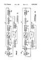
- FIG. 1is a block diagram of the electronic compass disclosed in the '843 patent to Hormel;
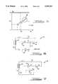
- FIG. 2is a depiction of the integrator output voltage range or "window" of the electronic compass system in the '843 patent to Hormel, showing the vehicle's and the earth's magnetic field voltage vectors V and R before compensation using the '843 compensation method.
- FIGS. 3A and 3Bare depictions of the same window as FIG. 2, but showing the vehicle's and earth's magnetic field voltage vectors V and R after compensation using the '843 compensation method.
- FIG. 4is a block diagram of an electronic compass incorporating the compensation circuit of the present invention.
- FIG. 5is a depiction of the integrator output voltage "window" of an electronic compass system incorporating the compensation circuit of the present invention, showing the vehicle's and earth's magnetic field voltage vectors, V and R after compensation;
- FIG. 6is a simplified schematic diagram of the compensation circuit and connection of the electronic compass shown in FIG. 1;
- FIG. 7is a simplified schematic diagram of the compensation circuit and connection of the present invention.
- FIG. 8is a block diagram an electronic compass incorporating a second embodiment of the present invention.
- FIG. 1there is shown a block diagram of the electronic compass system 10 of the '843 patent to Hormel.
- the heart of the systemis a microcomputer 12 which employs an 8-bit analog-to-digital converter 14.
- the microcomputer 12controls operation of the electronic compass system 10, beginning with a flux-gate driver 16.
- the flux-gate driver 16Upon receipt of a square-wave signal from the microcomputer 12, the flux-gate driver 16 adds enough drive to the signal to saturate a flux-gate 18.
- the operation of the flux-gate driver 16 and flux-gate 18are explained in the documents incorporated by reference, namely "A Magnetic Heading Reference for the Electro/Fluidic Autopilot" and "Magnetic Field Sensor and its Application to Automobiles, (SAE Paper No. 800123)".
- the flux-gate 18employs two sense coils oriented perpendicularly to one another. Voltages are induced across the sensor coils by the presence of the magnetic fields of the vehicle and the earth.
- the voltages from the sense coils of the flux-gate 18are selected by a multiplexer 20.
- the multiplexer 20is in communication with the microcomputer 12, which generates a signal for controlling a network for switching use of a four-pole bandpass filter 22, a synchronous detector 24 and an integrator 26 periodically from one sense coil to the other.
- the multiplexer 20is in communication with the four-pole bandpass filter 22, which filters out all but the second harmonic signals, whose amplitude is proportional to the earth's magnetic field.
- Second harmonic signalsare presented to the synchronous detector 24.
- the function of the synchronous detector 24is to select the portion of the filtered signals to be integrated by the integrator 26.
- the output of the synchronous detector 24is a half-wave rectified signal which is fed into the integrator 26.
- the output of integrator 26periodically switches back and forth between two DC levels corresponding to the two sense coils of the flux-gate 18.
- the output of integrator 26is stabilized by feeding back a current through resistor R f to the sense coils of the flux-gate 18.
- the feedback currenteventually generates an equal and opposite magnetic field versus that produced by the magnetic field sensed by the flux-gate 18. Therefore, the output voltages, V ox and V oy , of the integrator 26 are directly proportional to the sensed magnetic field by a constant R f which is the feedback resistance:
- V mx +R mxis the geometric addition (or resultant) of the voltages caused by the magnetic fields of the earth and the vehicle in the x coil.
- V my +R myis the geometric resultant at the magnetic field, of the earth and vehicle in the y coil
- Kis a Constant (related to the physical characteristics of the flux gate 18, such as its # of turns, permeability and the gain of filter 22 and integrator 26).
- the ranging circuit 28 used in the '843 patent to Hormelmoves the DC levels at the integrator output closer to the origin and toward a magnitude within the window.
- the ranging circuit 28generates a compensation field such that
- V nis the new vehicle magnetic field vector voltage
- Ris earth's magnetic field vector voltage
- V cis the compensation field vector voltage
- Heading informationis determined from the output of the integrator 26.
- the microcomputer 12is coupled to the integrator output through the 8-bit analog-to digital converter 14.
- the 8-bit analog-to-digital converter 14converts the DC levels to digital coordinates referenced to a cartesian coordinate system.
- the microcomputer 12divides the y-coordinate, corresponding to the DC level from one coil, by the x-coordinate, corresponding to the other coil, and takes the arctangent of the quotient using a piece-wise-linear-function-of-x routine to yield the vehicle's heading.
- the integrator 26employs operational amplifiers which have linear voltage output ranges of approximately 0 to V a volts.
- the linear voltage output rangeis approximately 0 to 10 volts. Since the voltages induced across the sense coils of the flux-gate 18 may be negative, these voltages must be modified for use in the integrator 26. Negative voltages are modified by tying the sense coils of the flux-gate 18 to a reference voltage of V cc , halfway between 0 and V a volts. In the '843 patent to Hormel, V cc is equal to 5 volts.
- the primary purpose of the ranging circuit 28is to bring the DC output levels of the integrator 26 into a range that can be resolved by the A/D, not to compensate for abnormally large vehicle magnetic fields. It accomplishes this through the use of negative feedback through resistor R f .
- the ranging circuit 28monitors the output of integrator 26 (through the A/D and microcomputer) and employs a variable voltage source, having an operational amplifier, to produce the compensation voltage.
- the outputs of the integrator 26 and ranging circuit 28are combined in a summing amplifier 30.
- FIG. 2there is shown a voltage window 34.
- the x and y axescorrespond to the two DC output levels V ox and V oy of the integrator 26.
- the limits of the window 30are determined by the output voltage range of the operational amplifiers within the integrator 26. This range is depicted as approximately 0 to V a volts.
- the voltage V ccis applied to the junction of the two sense coils and the integrator 26 and marks a reference for the origin O of the vehicle's magnetic field voltage vector V.
- the earth's magnetic field circle 36is the locus of points described by the earth's magnetic field voltage vector R as the vehicle changes heading.
- the vehicle's magnetic field voltage vector Vremains stationary with respect to the x and y axes, which are the frame of reference of the vehicle (and the flux-gate 18).
- FIGS. 3a and 3bthere is shown the window 34 of FIG. 2.
- the earth's magnetic field circle 36has been brought partially into the window 34 by the operation of the ranging circuit 28 of the electronic compass of FIG. 1.
- the compensation voltage vector V cis added to the vehicle's magnetic field voltage vector V to produce a new vehicle magnetic field voltage vector V n .
- the earth's magnetic field voltage vector Rremains the same as before compensation.
- the ranging circuit 28 in FIG. 1is incapable of producing enough feedback current to bring the earth's magnetic field circle 36 totally within the window 34.
- part of the earth's field circle 36remains outside the voltage window 34 after compensation.
- the microcomputer 12is incapable of generating accurate headings. If the earth's magnetic field circle 36 were totally outside the window 34 after compensation, then the microcomputer 12 would be incapable of generating any accurate headings, because the operational amplifiers of the integrator 26 would be in constant saturation. Thus, calibration under the method of the '462 and '843 patents would be impossible.
- FIG. 4there is shown a block diagram of the electronic compass system 38 of the present invention.
- the ranging circuit 28feeds the common junction of the sense coils of the flux-gate 18, the 4 pole bandpass filter 22 and the integrator 26. This produces a floating or shifting reference voltage V ref instead of a fixed voltage V cc .
- the reference voltage V refis controlled by the microcomputer 12 in response to the output of the integrator 26. When the operational amplifiers of the integrator 26 are in saturation, the microcomputer 12 signals the ranging circuit 28 to lower the reference voltage so as to bring the combination of the vehicle's and earth's magnetic field voltage vectors into the output voltage range of the integrator 26.
- the microcomputer 12if operational amplifier output is in cutoff (near zero) then the microcomputer signals the ranging circuit 28 to raise the reference voltage so as to bring the circle 36 into the window 34.
- the microcomputer 12(through the analog-to-digital converter 14) monitors the DC output levels, V ox and V oy , from the output of buffer amplifier 32, which corresponds to summing amplifier 30. If the microcomputer 12 senses that either voltage is high (near V a ) or low (near zero) then it signals the ranging circuit 28 to reduce or increase the corresponding DC output level by predetermined amounts until that DC output level is within the window 34.
- FIG. 5there is shown the voltage window 34 illustrating compensation under the present invention.
- the origin O of the vehicle's magnetic field vector voltage V of FIG. 2has been shifted to a point less than V cc in order to bring both the vehicle's magnetic field vector voltage V and the earth's magnetic field circle 36 within the window 34.
- the origin O of the vehicle's magnetic field vector voltage Vcan be moved anywhere within the window to bring both voltage vectors V and R into the window 34 for all vehicle headings.
- the reference voltages for each coil and its corresponding processing circuitcan be separately shifted.
- the microcomputer 12lets the ranging circuit 28 generate a reference voltage that may or may not be the same for both coils and their corresponding circuits. Once the two output voltages of the ranging circuit 28 are established, the microcomputer 12 does not vary them until the earth's field circle 36 is moved outside the window 34 by some other magnetic disturbance.
- FIG. 6there is shown a simplified schematic 40 of the compensation circuit of the '843 patent to Hormel.
- Sense coil 42is one of the two sense coils of the flux-gate 18.
- the multiplexer 20allows both sense coils to use the same circuit 40. Both sense coils are tied to a voltage V cc .
- Operational amplifier 44Arepresents part of the 4 pole bandpass filter which is referenced or biased by V cc .
- Operational amplifier 44represents the amplifier in the integrator 26 (which is referenced to V cc ) and is coupled to operational amplifier 46, which represents the summing amplifier 30, through resistance R 1 .
- each of the 4 pole bandpass filters 44A and 44 and the integratorhas a bias voltage that is referenced to V cc (same as the coil).
- Operational amplifier 48which represents the amplifier in the ranging circuit 28, is also coupled to the input of the amplifier 46 through resistance R 2 .
- the output of the operational amplifier 46is fed back to the sense coil 42 through a feedback resistor R.sub. f.
- the feedback currentis represented as I. Series coil resistance is represented by R c .
- the effectiveness of the circuit 40 in compensating for large vehicle magnetic fieldsis determined by the incremental change in feedback current ⁇ I produced for each incremental change in the output voltage ⁇ V c of the operational amplifier 48, and the maximum allowable feedback current per coil I max . From the circuit 40 of FIG. 5, the voltage V can be calculated as follows: ##EQU1## Since V cc is fixed to 0.5 V a , ##EQU2##
- FIG. 7there is shown the improved compensation circuit 50 of the present invention.
- the sense coil 42 of the flux-gate 18, the bias voltages of the 4 pole bandpass filter 22 and the integrator 26are now tied to a floating or shifting reference voltage V ref which is produced by the operational amplifier 52, corresponding to operational amplifier 48 of 6.
- the operational amplifier 44 and the operational amplifier 46are unchanged, as well as the feedback path through R f .
- the operational amplifier 46, corresponding to amplifier 32 of 4can be kept as an additional amplifier or eliminated.
- V ref and V ocan be any voltage from 0 to V a , ##EQU4##
- a comparison of the maximum feedback currents in each of the two compensation circuits 40 and 50also shows that the compensation circuit 50 of the present invention is more effective. From equations 6 and 10, the maximum feedback current I max of the present invention is twice as great as the maximum feedback current of the compensation circuit 40 in FIG. 6. Therefore, the present invention can compensate for sensed magnetic fields twice as strong.
- the present inventionmakes calibration under the method of the '462 patent possible for abnormally large vehicle magnetic fields.
- Another advantage of the compensation circuit 50 of the present inventionis that it moves the earth's magnetic field circle 36 totally within the window 34 without reducing the radius R of the earth's magnetic field circle 36. Compensation is accomplished by shifting the origin O of the vehicle's magnetic field voltage vector V. In the compensation circuit 40 of FIG. 6, the origin O of the vehicle's magnetic field voltage vector V is held at V cc and compensation is produced by decreasing the magnitude of the vehicle's magnetic field voltage vector V. The resolving power of the analog-to-digital converter 14 determines the maximum current that will permit resolution of the earth's magnetic field voltage vector R. In the compensation circuit 50 of the present invention, the trade-off between increased feedback current I and decreased resolving power are not present because the vector magnitude of the R remains the same.
- the compensation circuit 50 of the present inventionallows the DC output levels, V ox and V oy , to be sampled from the output of the buffer amplifier 32. This effectively places tile buffer amplifier 32 outside the feedback loop.
- the summing amplifier 30is within the feedback loop of the compensation circuit 40; therefore, minor variations in output current due to temperature variations become magnified and represent a source of error.
- the present inventioncan be easily implemented by merely connecting the output of the ranging circuit 28 to the common junction of the sense coils of the flux-gate 18, the 4 pole bandpass filter bias point and the integrator bias point.
- the present inventionis not limited to vehicles and is not bound by the usage of a multiplexing scheme.
- the sensed magnetic field in each coilmay be processed separately, using bandpass filters 62 and 63, synchronous detectors 64 and 65, integrators 66 and 67, ranging circuits 68 and 69, feedback resistances R fx and R fy and buffer amplifiers 70 and 71.
- the sense coilsare not tied to a common junction.
- the ranging circuitcould be any type of circuit that generates a variable output voltage that is controlled by a microcontroller or other controlling circuit, such as pulse width modulation circuits.
Landscapes
- Engineering & Computer Science (AREA)
- Radar, Positioning & Navigation (AREA)
- Remote Sensing (AREA)
- Physics & Mathematics (AREA)
- General Physics & Mathematics (AREA)
- Life Sciences & Earth Sciences (AREA)
- Environmental & Geological Engineering (AREA)
- General Life Sciences & Earth Sciences (AREA)
- Geology (AREA)
- Electromagnetism (AREA)
- Measuring Magnetic Variables (AREA)
Abstract
Description
V.sub.ox =KR.sub.f (V.sub.mx +R.sub.mx).
V.sub.oy =KR.sub.f (V.sub.my +R.sub.my)
V.sub.n +R=V+R+V.sub.c
or
V.sub.n =V+V.sub.c
Claims (7)
Priority Applications (1)
| Application Number | Priority Date | Filing Date | Title |
|---|---|---|---|
| US07/815,267US5353241A (en) | 1991-12-27 | 1991-12-27 | Shifting system and method for an electronic compass system |
Applications Claiming Priority (1)
| Application Number | Priority Date | Filing Date | Title |
|---|---|---|---|
| US07/815,267US5353241A (en) | 1991-12-27 | 1991-12-27 | Shifting system and method for an electronic compass system |
Publications (1)
| Publication Number | Publication Date |
|---|---|
| US5353241Atrue US5353241A (en) | 1994-10-04 |
Family
ID=25217334
Family Applications (1)
| Application Number | Title | Priority Date | Filing Date |
|---|---|---|---|
| US07/815,267Expired - LifetimeUS5353241A (en) | 1991-12-27 | 1991-12-27 | Shifting system and method for an electronic compass system |
Country Status (1)
| Country | Link |
|---|---|
| US (1) | US5353241A (en) |
Cited By (3)
| Publication number | Priority date | Publication date | Assignee | Title |
|---|---|---|---|---|
| US5737226A (en)* | 1995-06-05 | 1998-04-07 | Prince Corporation | Vehicle compass system with automatic calibration |
| US6643941B2 (en)* | 1999-05-27 | 2003-11-11 | Johnson Controls Technology Company | Vehicle compass system with continuous automatic calibration |
| CN101807350A (en)* | 2010-03-24 | 2010-08-18 | 天津信电科技发展有限公司 | Method for improving accuracy of geomagnetic parking space detector |
Citations (14)
| Publication number | Priority date | Publication date | Assignee | Title |
|---|---|---|---|---|
| US3899834A (en)* | 1972-10-02 | 1975-08-19 | Westinghouse Electric Corp | Electronic compass system |
| US3991361A (en)* | 1975-03-27 | 1976-11-09 | Westinghouse Electric Corporation | Semi-automatic compass calibrator apparatus for a vehicle mounted flux gate compass system to cancel out effect of local magnetic disturbances |
| GB2056686A (en)* | 1979-08-10 | 1981-03-18 | Sperry Corp | Flux valve compass system |
| US4424631A (en)* | 1982-03-02 | 1984-01-10 | Prince Corporation | Electrical compass |
| US4425717A (en)* | 1982-06-24 | 1984-01-17 | Prince Corporation | Vehicle magnetic sensor |
| US4505054A (en)* | 1983-05-25 | 1985-03-19 | Prince Corporation | Magnetic sensor mounting system |
| JPS60135814A (en)* | 1983-12-26 | 1985-07-19 | Nec Corp | Azimuth detecting apparatus |
| US4546551A (en)* | 1983-03-24 | 1985-10-15 | Prince Corporation | Electrical control system |
| US4622646A (en)* | 1982-09-08 | 1986-11-11 | The Commonwealth Of Australia Of C/-Department Of Defence Support | Arrangements for correcting compasses |
| US4622843A (en)* | 1985-12-27 | 1986-11-18 | Hormel Ronald F | Simplified calibration technique and auto ranging circuit for an electronic compass control circuit |
| US4677381A (en)* | 1984-10-19 | 1987-06-30 | Prince Corporation | Flux-gate sensor electrical drive method and circuit |
| US4698912A (en)* | 1985-12-11 | 1987-10-13 | The Laitram Corporation | Magnetic compass calibration |
| US4750349A (en)* | 1985-12-27 | 1988-06-14 | Chrysler Motors Corporation | Microcomputer controlled quick ranging technique and digital filter |
| US4807462A (en)* | 1987-04-03 | 1989-02-28 | Chrysler Motors Corporation | Method for performing automatic calibrations in an electronic compass |
- 1991
- 1991-12-27USUS07/815,267patent/US5353241A/ennot_activeExpired - Lifetime
Patent Citations (14)
| Publication number | Priority date | Publication date | Assignee | Title |
|---|---|---|---|---|
| US3899834A (en)* | 1972-10-02 | 1975-08-19 | Westinghouse Electric Corp | Electronic compass system |
| US3991361A (en)* | 1975-03-27 | 1976-11-09 | Westinghouse Electric Corporation | Semi-automatic compass calibrator apparatus for a vehicle mounted flux gate compass system to cancel out effect of local magnetic disturbances |
| GB2056686A (en)* | 1979-08-10 | 1981-03-18 | Sperry Corp | Flux valve compass system |
| US4424631A (en)* | 1982-03-02 | 1984-01-10 | Prince Corporation | Electrical compass |
| US4425717A (en)* | 1982-06-24 | 1984-01-17 | Prince Corporation | Vehicle magnetic sensor |
| US4622646A (en)* | 1982-09-08 | 1986-11-11 | The Commonwealth Of Australia Of C/-Department Of Defence Support | Arrangements for correcting compasses |
| US4546551A (en)* | 1983-03-24 | 1985-10-15 | Prince Corporation | Electrical control system |
| US4505054A (en)* | 1983-05-25 | 1985-03-19 | Prince Corporation | Magnetic sensor mounting system |
| JPS60135814A (en)* | 1983-12-26 | 1985-07-19 | Nec Corp | Azimuth detecting apparatus |
| US4677381A (en)* | 1984-10-19 | 1987-06-30 | Prince Corporation | Flux-gate sensor electrical drive method and circuit |
| US4698912A (en)* | 1985-12-11 | 1987-10-13 | The Laitram Corporation | Magnetic compass calibration |
| US4622843A (en)* | 1985-12-27 | 1986-11-18 | Hormel Ronald F | Simplified calibration technique and auto ranging circuit for an electronic compass control circuit |
| US4750349A (en)* | 1985-12-27 | 1988-06-14 | Chrysler Motors Corporation | Microcomputer controlled quick ranging technique and digital filter |
| US4807462A (en)* | 1987-04-03 | 1989-02-28 | Chrysler Motors Corporation | Method for performing automatic calibrations in an electronic compass |
Cited By (11)
| Publication number | Priority date | Publication date | Assignee | Title |
|---|---|---|---|---|
| US5737226A (en)* | 1995-06-05 | 1998-04-07 | Prince Corporation | Vehicle compass system with automatic calibration |
| US6643941B2 (en)* | 1999-05-27 | 2003-11-11 | Johnson Controls Technology Company | Vehicle compass system with continuous automatic calibration |
| US20040123475A1 (en)* | 1999-05-27 | 2004-07-01 | Johnson Controls Technology Company | Vehicle compass system with continuous automatic calibration |
| US6857194B2 (en)* | 1999-05-27 | 2005-02-22 | Johnson Controls Technology Company | Vehicle compass system with continuous automatic calibration |
| US6964108B2 (en) | 1999-05-27 | 2005-11-15 | Johnson Controls Technology Company | Vehicle compass system with continuous automatic calibration |
| US7127823B2 (en) | 1999-05-27 | 2006-10-31 | Johnson Controls Technology Company | Vehicle compass system with continuous automatic calibration |
| US7191533B2 (en) | 1999-05-27 | 2007-03-20 | Johnson Controls Technology Company | Vehicle compass system with continuous automatic calibration |
| US7353614B2 (en)* | 1999-05-27 | 2008-04-08 | Johnson Controls Technology Company | Vehicle compass system with continuous automatic calibration |
| US7458166B2 (en) | 1999-05-27 | 2008-12-02 | Johnson Controls Technology Company | Vehicle compass system with continuous automatic calibration |
| CN101807350A (en)* | 2010-03-24 | 2010-08-18 | 天津信电科技发展有限公司 | Method for improving accuracy of geomagnetic parking space detector |
| CN101807350B (en)* | 2010-03-24 | 2012-01-18 | 天津信电科技发展有限公司 | Method for improving accuracy of geomagnetic parking space detector |
Similar Documents
| Publication | Publication Date | Title |
|---|---|---|
| US4622843A (en) | Simplified calibration technique and auto ranging circuit for an electronic compass control circuit | |
| KR0182252B1 (en) | Converter circuit | |
| US5297065A (en) | Magnetic transient detection and calibration technique for an auto-calibrating compass | |
| US3696518A (en) | Vehicle direction sensing and steering systems using magnetic flux responsive means | |
| US5353241A (en) | Shifting system and method for an electronic compass system | |
| CA1266172A (en) | Multiplexing of a bandpass filter circuit to work with a flux-gate sensor output | |
| EP0227888B1 (en) | Microcomputer-controlled quick calibration technique for an electronic compass | |
| US4908561A (en) | Servo amplifier circuit | |
| US3974425A (en) | Isolator circuit with improved frequency response | |
| US4079803A (en) | Electromagnetic guidance system | |
| US4160488A (en) | Extended width sensor | |
| US5351204A (en) | Scaling system and method for an electronic compass | |
| US5333110A (en) | Electronic magnetic compass system and method for interpreting directions of a vehicle | |
| US4460856A (en) | Two-phase brushless motor driving circuit | |
| GB2219898A (en) | Automatic gain control circuit | |
| US5416665A (en) | Vehicle electromagnetic clutch control device | |
| US4059796A (en) | Second harmonic magnetic field detection circuit with means to rectify the sensed signal | |
| JPH09257835A (en) | Current detector | |
| US4523153A (en) | Variable gain amplifier | |
| GB2080955A (en) | Earth field compensation for a magnetic detector | |
| GB2073524A (en) | Class ab amplifying circuit | |
| JPS61169910A (en) | Detecting method of positional shift | |
| JPH0260964B2 (en) | ||
| SU1328801A1 (en) | Device for obtaining the given values of direct current | |
| SU1520633A1 (en) | Device for measuring speed of movement of working element of linear asynchronous electric motor |
Legal Events
| Date | Code | Title | Description |
|---|---|---|---|
| AS | Assignment | Owner name:CHRYSLER CORPORATION, MICHIGAN Free format text:ASSIGNMENT OF ASSIGNORS INTEREST.;ASSIGNOR:AL-ATTAR, RAFI A.;REEL/FRAME:006042/0433 Effective date:19911111 | |
| STCF | Information on status: patent grant | Free format text:PATENTED CASE | |
| CC | Certificate of correction | ||
| FPAY | Fee payment | Year of fee payment:4 | |
| FPAY | Fee payment | Year of fee payment:8 | |
| SULP | Surcharge for late payment | Year of fee payment:7 | |
| FPAY | Fee payment | Year of fee payment:12 | |
| AS | Assignment | Owner name:WILMINGTON TRUST COMPANY, DELAWARE Free format text:GRANT OF SECURITY INTEREST IN PATENT RIGHTS - FIRST PRIORITY;ASSIGNOR:CHRYSLER LLC;REEL/FRAME:019773/0001 Effective date:20070803 Owner name:WILMINGTON TRUST COMPANY,DELAWARE Free format text:GRANT OF SECURITY INTEREST IN PATENT RIGHTS - FIRST PRIORITY;ASSIGNOR:CHRYSLER LLC;REEL/FRAME:019773/0001 Effective date:20070803 | |
| AS | Assignment | Owner name:WILMINGTON TRUST COMPANY, DELAWARE Free format text:GRANT OF SECURITY INTEREST IN PATENT RIGHTS - SECOND PRIORITY;ASSIGNOR:CHRYSLER LLC;REEL/FRAME:019767/0810 Effective date:20070803 Owner name:WILMINGTON TRUST COMPANY,DELAWARE Free format text:GRANT OF SECURITY INTEREST IN PATENT RIGHTS - SECOND PRIORITY;ASSIGNOR:CHRYSLER LLC;REEL/FRAME:019767/0810 Effective date:20070803 | |
| AS | Assignment | Owner name:DAIMLERCHRYSLER CORPORATION, MICHIGAN Free format text:CHANGE OF NAME;ASSIGNOR:CHRYSLER CORPORATION;REEL/FRAME:021826/0034 Effective date:19981116 | |
| AS | Assignment | Owner name:CHRYSLER LLC, MICHIGAN Free format text:CHANGE OF NAME;ASSIGNOR:DAIMLERCHRYSLER COMPANY LLC;REEL/FRAME:021832/0233 Effective date:20070727 Owner name:DAIMLERCHRYSLER COMPANY LLC, MICHIGAN Free format text:CHANGE OF NAME;ASSIGNOR:DAIMLERCHRYSLER CORPORATION;REEL/FRAME:021832/0256 Effective date:20070329 | |
| AS | Assignment | Owner name:US DEPARTMENT OF THE TREASURY, DISTRICT OF COLUMBI Free format text:GRANT OF SECURITY INTEREST IN PATENT RIGHTS - THIR;ASSIGNOR:CHRYSLER LLC;REEL/FRAME:022259/0188 Effective date:20090102 Owner name:US DEPARTMENT OF THE TREASURY,DISTRICT OF COLUMBIA Free format text:GRANT OF SECURITY INTEREST IN PATENT RIGHTS - THIR;ASSIGNOR:CHRYSLER LLC;REEL/FRAME:022259/0188 Effective date:20090102 | |
| AS | Assignment | Owner name:CHRYSLER LLC, MICHIGAN Free format text:RELEASE BY SECURED PARTY;ASSIGNOR:US DEPARTMENT OF THE TREASURY;REEL/FRAME:022902/0164 Effective date:20090608 Owner name:CHRYSLER LLC,MICHIGAN Free format text:RELEASE BY SECURED PARTY;ASSIGNOR:US DEPARTMENT OF THE TREASURY;REEL/FRAME:022902/0164 Effective date:20090608 | |
| AS | Assignment | Owner name:CHRYSLER LLC, MICHIGAN Free format text:RELEASE OF SECURITY INTEREST IN PATENT RIGHTS - FIRST PRIORITY;ASSIGNOR:WILMINGTON TRUST COMPANY;REEL/FRAME:022910/0498 Effective date:20090604 Owner name:CHRYSLER LLC, MICHIGAN Free format text:RELEASE OF SECURITY INTEREST IN PATENT RIGHTS - SECOND PRIORITY;ASSIGNOR:WILMINGTON TRUST COMPANY;REEL/FRAME:022910/0740 Effective date:20090604 Owner name:NEW CARCO ACQUISITION LLC, MICHIGAN Free format text:ASSIGNMENT OF ASSIGNORS INTEREST;ASSIGNOR:CHRYSLER LLC;REEL/FRAME:022915/0001 Effective date:20090610 Owner name:THE UNITED STATES DEPARTMENT OF THE TREASURY, DIST Free format text:SECURITY AGREEMENT;ASSIGNOR:NEW CARCO ACQUISITION LLC;REEL/FRAME:022915/0489 Effective date:20090610 Owner name:CHRYSLER LLC,MICHIGAN Free format text:RELEASE OF SECURITY INTEREST IN PATENT RIGHTS - FIRST PRIORITY;ASSIGNOR:WILMINGTON TRUST COMPANY;REEL/FRAME:022910/0498 Effective date:20090604 Owner name:CHRYSLER LLC,MICHIGAN Free format text:RELEASE OF SECURITY INTEREST IN PATENT RIGHTS - SECOND PRIORITY;ASSIGNOR:WILMINGTON TRUST COMPANY;REEL/FRAME:022910/0740 Effective date:20090604 Owner name:NEW CARCO ACQUISITION LLC,MICHIGAN Free format text:ASSIGNMENT OF ASSIGNORS INTEREST;ASSIGNOR:CHRYSLER LLC;REEL/FRAME:022915/0001 Effective date:20090610 Owner name:THE UNITED STATES DEPARTMENT OF THE TREASURY,DISTR Free format text:SECURITY AGREEMENT;ASSIGNOR:NEW CARCO ACQUISITION LLC;REEL/FRAME:022915/0489 Effective date:20090610 | |
| AS | Assignment | Owner name:CHRYSLER GROUP LLC, MICHIGAN Free format text:CHANGE OF NAME;ASSIGNOR:NEW CARCO ACQUISITION LLC;REEL/FRAME:022919/0126 Effective date:20090610 Owner name:CHRYSLER GROUP LLC,MICHIGAN Free format text:CHANGE OF NAME;ASSIGNOR:NEW CARCO ACQUISITION LLC;REEL/FRAME:022919/0126 Effective date:20090610 | |
| AS | Assignment | Owner name:CHRYSLER GROUP GLOBAL ELECTRIC MOTORCARS LLC, NORT Free format text:RELEASE BY SECURED PARTY;ASSIGNOR:THE UNITED STATES DEPARTMENT OF THE TREASURY;REEL/FRAME:026343/0298 Effective date:20110524 Owner name:CHRYSLER GROUP LLC, MICHIGAN Free format text:RELEASE BY SECURED PARTY;ASSIGNOR:THE UNITED STATES DEPARTMENT OF THE TREASURY;REEL/FRAME:026343/0298 Effective date:20110524 | |
| AS | Assignment | Owner name:CITIBANK, N.A., NEW YORK Free format text:SECURITY AGREEMENT;ASSIGNOR:CHRYSLER GROUP LLC;REEL/FRAME:026404/0123 Effective date:20110524 | |
| AS | Assignment | Owner name:CITIBANK, N.A., NEW YORK Free format text:SECURITY AGREEMENT;ASSIGNOR:CHRYSLER GROUP LLC;REEL/FRAME:026435/0652 Effective date:20110524 |