US5352226A - Side locking system rotatable in all directions for use in spinal surgery - Google Patents
Side locking system rotatable in all directions for use in spinal surgeryDownload PDFInfo
- Publication number
- US5352226A US5352226AUS08/014,525US1452593AUS5352226AUS 5352226 AUS5352226 AUS 5352226AUS 1452593 AUS1452593 AUS 1452593AUS 5352226 AUS5352226 AUS 5352226A
- Authority
- US
- United States
- Prior art keywords
- side locking
- locking block
- spinal
- rotatable
- slit
- Prior art date
- Legal status (The legal status is an assumption and is not a legal conclusion. Google has not performed a legal analysis and makes no representation as to the accuracy of the status listed.)
- Expired - Lifetime
Links
- 238000001356surgical procedureMethods0.000titleclaimsabstractdescription4
- 238000010276constructionMethods0.000claimsabstractdescription5
- 230000006835compressionEffects0.000claimsabstract2
- 238000007906compressionMethods0.000claimsabstract2
- VYZAMTAEIAYCRO-UHFFFAOYSA-NChromiumChemical compound[Cr]VYZAMTAEIAYCRO-UHFFFAOYSA-N0.000description1
- 229910000531Co alloyInorganic materials0.000description1
- 229910000599Cr alloyInorganic materials0.000description1
- 229910001182Mo alloyInorganic materials0.000description1
- ZOKXTWBITQBERF-UHFFFAOYSA-NMolybdenumChemical compound[Mo]ZOKXTWBITQBERF-UHFFFAOYSA-N0.000description1
- 238000005452bendingMethods0.000description1
- 239000011651chromiumSubstances0.000description1
- 230000002950deficientEffects0.000description1
- 230000000694effectsEffects0.000description1
- 238000002513implantationMethods0.000description1
- 239000000463materialSubstances0.000description1
- 239000007769metal materialSubstances0.000description1
- 239000011733molybdenumSubstances0.000description1
- 230000000087stabilizing effectEffects0.000description1
- 239000010935stainless steelSubstances0.000description1
- 229910001220stainless steelInorganic materials0.000description1
Images

Classifications
- A—HUMAN NECESSITIES
- A61—MEDICAL OR VETERINARY SCIENCE; HYGIENE
- A61B—DIAGNOSIS; SURGERY; IDENTIFICATION
- A61B17/00—Surgical instruments, devices or methods
- A61B17/56—Surgical instruments or methods for treatment of bones or joints; Devices specially adapted therefor
- A61B17/58—Surgical instruments or methods for treatment of bones or joints; Devices specially adapted therefor for osteosynthesis, e.g. bone plates, screws or setting implements
- A61B17/68—Internal fixation devices, including fasteners and spinal fixators, even if a part thereof projects from the skin
- A61B17/70—Spinal positioners or stabilisers, e.g. stabilisers comprising fluid filler in an implant
- A61B17/7001—Screws or hooks combined with longitudinal elements which do not contact vertebrae
- A61B17/7035—Screws or hooks, wherein a rod-clamping part and a bone-anchoring part can pivot relative to each other
- A61B17/7037—Screws or hooks, wherein a rod-clamping part and a bone-anchoring part can pivot relative to each other wherein pivoting is blocked when the rod is clamped
- A—HUMAN NECESSITIES
- A61—MEDICAL OR VETERINARY SCIENCE; HYGIENE
- A61B—DIAGNOSIS; SURGERY; IDENTIFICATION
- A61B17/00—Surgical instruments, devices or methods
- A61B17/56—Surgical instruments or methods for treatment of bones or joints; Devices specially adapted therefor
- A61B17/58—Surgical instruments or methods for treatment of bones or joints; Devices specially adapted therefor for osteosynthesis, e.g. bone plates, screws or setting implements
- A61B17/68—Internal fixation devices, including fasteners and spinal fixators, even if a part thereof projects from the skin
- A61B17/70—Spinal positioners or stabilisers, e.g. stabilisers comprising fluid filler in an implant
- A61B17/7001—Screws or hooks combined with longitudinal elements which do not contact vertebrae
- A61B17/7002—Longitudinal elements, e.g. rods
- A61B17/7004—Longitudinal elements, e.g. rods with a cross-section which varies along its length
- A61B17/7008—Longitudinal elements, e.g. rods with a cross-section which varies along its length with parts of, or attached to, the longitudinal elements, bearing against an outside of the screw or hook heads, e.g. nuts on threaded rods
- A—HUMAN NECESSITIES
- A61—MEDICAL OR VETERINARY SCIENCE; HYGIENE
- A61B—DIAGNOSIS; SURGERY; IDENTIFICATION
- A61B17/00—Surgical instruments, devices or methods
- A61B17/56—Surgical instruments or methods for treatment of bones or joints; Devices specially adapted therefor
- A61B17/58—Surgical instruments or methods for treatment of bones or joints; Devices specially adapted therefor for osteosynthesis, e.g. bone plates, screws or setting implements
- A61B17/68—Internal fixation devices, including fasteners and spinal fixators, even if a part thereof projects from the skin
- A61B17/70—Spinal positioners or stabilisers, e.g. stabilisers comprising fluid filler in an implant
- A61B17/7001—Screws or hooks combined with longitudinal elements which do not contact vertebrae
- A61B17/7041—Screws or hooks combined with longitudinal elements which do not contact vertebrae with single longitudinal rod offset laterally from single row of screws or hooks
Definitions
- the present inventionrelates to a spinal locking system, and more particularly to a side locking system which can be rotated in all directions so as to render an effective support to a vertebra under treatment.
- the Diapason systemhas an advantage that it can be rotated in all directions; nevertheless it lacks an efficient locking effect in view of the fact that it is provided with the curved locking rod and that its spinal pins are ineffective when used at a location slightly far away from the locking rod.
- the systems of the U.S. Pat. Nos. 4,827,918; 5,047,029; and 5,053,034are also limited in that they can be caused to make an angular adjustment of the spinal pins in only one direction, or in two directions at best, and that they are vulnerable to a mechanical failure due to their complicated structural make-up.
- a side locking systemwhich can be rotated in all directions and is composed of a side locking member, a spherical liner, and a fastening element.
- the side locking memberis made up of a side locking block and a rotatable locking block.
- the side locking blockhas a through hole intended for use in receiving therein a spinal locking rod and a fastening slit substantially perpendicular to the axis of the through hole.
- the rotatable locking blockcontains a rotatable receiving mount of a spherical construction.
- the spherical lineris received in the rotatable locking block and provided with a hollow portion intended for use in receiving therein the spinal pin and the like.
- the spherical lineris further provided with a fastening slit.
- the fastening elementis used to fasten from the outside of the side locking block directly onto the fastening slit of the side locking block and indirectly onto the spherical liner, so as to cause the through hole of the side locking block to hold firmly the spinal locking rod.
- FIG. 1-ashows a top view of the preferred embodiment of the present invention.
- FIG. 1-bshows a cross-sectional side view of the embodiment shown in FIG. 1-a.
- FIG. 2shows a schematic view of a spherical liner of the preferred embodiment of the present invention.
- FIG. 3shows a schematic view of a fastening element (without a fastening nut) of the preferred embodiment of the present invention.
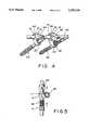
- FIG. 4shows a perspective view of the preferred embodiment in combination, according to the present invention.
- FIG. 5shows a schematic view illustrating the fastening manner of the preferred embodiment of the present invention.
- the preferred embodiment of the present inventionis shown to comprise a side locking block 10, a rotatable locking block 20, a spherical liner 30, and a fastening element 40.
- the side locking block 10has a through hole 11 intended for use in receiving and holding a spinal locking rod 50 and has a fastening slit 12 substantially perpendicular to the axis of the through hole 11.
- the rotatable locking block 20contains therein a rotatable receiving mount 21 of a spherical construction.
- the spherical liner 30is mounted in the rotatable locking block 20 and provided with a fastening slit 31 and a hollow portion intended for use in receiving and holding a spinal pin 60.
- the fastening element 40has a slit 41, a threaded portion 42, and a nut 43.
- the fastening element 40is used to fastened from the outside of the side locking block 10 directly onto the fastening slit 12 of the side locking block 10 and indirectly onto the spherical liner 30, so as to cause the through hole 11 of the side locking block 10 to hold firmly the spinal locking rod 50.
- two spinal pins 60are inserted respectively into each of two vertebrae (not shown in the drawing) adjacent to a deformed vertebra (not shown in the drawing).
- a rigid connection between the two spinal pins 60 and the spinal locking rod 50is attained by engaging the nut 43 with the threaded portion 42 in the directions indicated by arrows as shown in FIG. 5.
- the angle at which the spinal pin 60 is inserted into the vertebracan be adjusted at will, in view of the fact that the spherical liner 30 is mounted in the rotatable locking block 20 which can be rotated in all directions.
- the fastening slit 12 of the side locking block 10is forced to close, thereby causing the rotatable locking block 20 to clamp securely the spherical liner 30.
- the slit 31 of the spherical liner 30is in turn forced to close so that the spherical liner 30 is caused to clamp securely the spinal pin 60, which is thus rigidly connected with the spinal locking rod 50, as shown in FIG. 4.
- the component parts of the preferred embodiment of the present invention described abovemay be made of such biocompatible metal materials as a 316 LVM stainless steel, a Ti-6-4 material, an alloy of cobalt, molybdenum and chromium, etc.
- the side locking block 10 of the present inventionmay be of any shape, preferably a rectangular shape or something similar to a rectangular shape.
- the through hole 11 located at the center of the side locking block 10should be so shaped and dimensioned as to receive and hold the spinal locking rod 50.
- the through hole 11 of the side locking block 10is preferably circular, or oval, or rectangular, or something similar to a rectangular shape in its cross section. It is suggested that the through hole 11 has an oval, or a rectangular cross section, which facilitates the adjustment of the position of the spinal locking rod 50 in the through hole 11.
- the fastening slit 12 of the side locking block 10is substantially or nearly perpendicular to the axis of the through hole 11 or the axis of the spinal locking rod 50.
- the fastening slit 12should be located on or near the major diameter of the through hole 11. If the through hole 11 is circular in its cross section, the fastening slit 12 is preferably located in such a manner that the fastening slit 12 is directed toward the center of the circular cross section of the through hole 11, and that the fastening slit 12 extends from one side of the side locking block 10 to reach the rotatable receiving mount 21 of the rotatable locking block 20.
- the fastening slit 12may be also constructed in such a manner that it does not penetrate through the rotatable locking block 20.
- the rotatable locking block 20 of the present inventionmay be of any shape.
- the rotatable receiving mount 21 of the rotatable locking block 20is spherical in shape, with the exception of the openings located at both ends of the rotatable receiving mount 21.
- the spherical liner 30is similarly constructed such that it has an outer diameter corresponding to an inner diameter of the rotatable receiving mount 21.
- the hollow portion of the spherical liner 30is so shaped and dimensioned as to receive and hold the upper portion of the spinal pin 60.
- the hollow portion of the spherical liner 30is of a cylindrical construction.
- the slit 31 of the spherical liner 30is so constructed that the slit 31 penetrates from the outer portion of the spherical liner 30 toward the inner portion of the spherical liner 30.
- the slit 31is preferably oriented in an oblique manner relative to an axis defined by the hollow portion of spherical liner 30.
- any of the prior art fastening elementsmay be used as the fastening element 40 of the present invention, which serves the purpose of tightening the fastening slit 12 of the side locking block 10 so that the side locking block 10 is actuated to clamp securely the spinal locking rod 50, and that the rotatable receiving mount 21 of the rotatable locking block 20 is compressed to an extent that the spherical liner 30 is so tightened as to hold securely the spinal pin 60.
- the spinal pin 60can be disposed in any desired orientation before it is inserted into a vertebra, in view of the fact that the rotatable receiving mount 21 of the rotatable locking block 20 can be rotated in all directions relative to the spinal locking pin 60.
Landscapes
- Health & Medical Sciences (AREA)
- Orthopedic Medicine & Surgery (AREA)
- Life Sciences & Earth Sciences (AREA)
- Neurology (AREA)
- Surgery (AREA)
- Heart & Thoracic Surgery (AREA)
- Engineering & Computer Science (AREA)
- Biomedical Technology (AREA)
- Nuclear Medicine, Radiotherapy & Molecular Imaging (AREA)
- Medical Informatics (AREA)
- Molecular Biology (AREA)
- Animal Behavior & Ethology (AREA)
- General Health & Medical Sciences (AREA)
- Public Health (AREA)
- Veterinary Medicine (AREA)
- Surgical Instruments (AREA)
Abstract
Description
The present invention relates to a spinal locking system, and more particularly to a side locking system which can be rotated in all directions so as to render an effective support to a vertebra under treatment.
The implementation of a surgical implantation of the prior art vertebral locking and retrieving system requires that the spinal pins or the Lugue hooks which are inserted into vertebrae must be aligned. If a surgeon performing the surgical operation fails to attain such an alignment of the spinal pins or the Lugue hooks, he or she is forced to remedy the situation by bending the locking rod of the implanted system. Such a practice is not desirable because it often fails to bring about a satisfactory result of stabilizing the vertebrae under treatment.
With a view to overcoming the serious drawback of the prior art system described above, a variety of improved systems are disclosed in the U.S. Pat. Nos. 5,030,220; 4,827,918; 5,053,034; and 5,047,029. In addition to the above-identified patents, an improved system known as Diapason is disclosed by a French Company called Dimso. All these improved systems are by no means free from shortcomings. The improved system disclosed in the U.S. Pat. No. 5,030,220 is defective in design in that the clamp located at the curved portion of the locking rod can not be fastened effectively and that the clamp is capable of making only a unidirectional adjustment of the fastening angle of the spinal pins. The Diapason system has an advantage that it can be rotated in all directions; nevertheless it lacks an efficient locking effect in view of the fact that it is provided with the curved locking rod and that its spinal pins are ineffective when used at a location slightly far away from the locking rod. The systems of the U.S. Pat. Nos. 4,827,918; 5,047,029; and 5,053,034 are also limited in that they can be caused to make an angular adjustment of the spinal pins in only one direction, or in two directions at best, and that they are vulnerable to a mechanical failure due to their complicated structural make-up.
It is, therefore the primary objective of the present invention to provide a side locking system rotatable in all directions for use in a spinal surgery.
It is another objective of the present invention to provide a side locking system which can be rotated in all directions and has a spinal locking rod united securely with spinal pins.
It is still another objective of the present invention to provide a side locking system which can be rotated in all directions and is composed of a side locking member rotatable in all directions, a spherical liner and a fastening element.
In keeping with the principles of the present invention, the foregoing objectives of the present invention are accomplished by a side locking system which can be rotated in all directions and is composed of a side locking member, a spherical liner, and a fastening element.
The side locking member is made up of a side locking block and a rotatable locking block. The side locking block has a through hole intended for use in receiving therein a spinal locking rod and a fastening slit substantially perpendicular to the axis of the through hole. The rotatable locking block contains a rotatable receiving mount of a spherical construction.
The spherical liner is received in the rotatable locking block and provided with a hollow portion intended for use in receiving therein the spinal pin and the like. The spherical liner is further provided with a fastening slit.
The fastening element is used to fasten from the outside of the side locking block directly onto the fastening slit of the side locking block and indirectly onto the spherical liner, so as to cause the through hole of the side locking block to hold firmly the spinal locking rod.
The foregoing objectives, features, structures and functions of the present invention will be better understood by studying the following detailed description of a preferred embodiment of the present invention in conjunction with the drawings provided herewith.
FIG. 1-a shows a top view of the preferred embodiment of the present invention.
FIG. 1-b shows a cross-sectional side view of the embodiment shown in FIG. 1-a.
FIG. 2 shows a schematic view of a spherical liner of the preferred embodiment of the present invention.
FIG. 3 shows a schematic view of a fastening element (without a fastening nut) of the preferred embodiment of the present invention.
FIG. 4 shows a perspective view of the preferred embodiment in combination, according to the present invention.
FIG. 5 shows a schematic view illustrating the fastening manner of the preferred embodiment of the present invention.
Referring to all drawings provided herewith, the preferred embodiment of the present invention is shown to comprise aside locking block 10, arotatable locking block 20, aspherical liner 30, and afastening element 40.
Theside locking block 10 has a through hole 11 intended for use in receiving and holding aspinal locking rod 50 and has a fastening slit 12 substantially perpendicular to the axis of the through hole 11. Therotatable locking block 20 contains therein arotatable receiving mount 21 of a spherical construction.
Thespherical liner 30 is mounted in therotatable locking block 20 and provided with afastening slit 31 and a hollow portion intended for use in receiving and holding aspinal pin 60.
Thefastening element 40 has aslit 41, a threadedportion 42, and anut 43. Thefastening element 40 is used to fastened from the outside of theside locking block 10 directly onto thefastening slit 12 of theside locking block 10 and indirectly onto thespherical liner 30, so as to cause the through hole 11 of theside locking block 10 to hold firmly thespinal locking rod 50.
As illustrated in FIG. 4, twospinal pins 60 are inserted respectively into each of two vertebrae (not shown in the drawing) adjacent to a deformed vertebra (not shown in the drawing). A rigid connection between the twospinal pins 60 and thespinal locking rod 50 is attained by engaging thenut 43 with the threadedportion 42 in the directions indicated by arrows as shown in FIG. 5.
Before theside locking block 10 is tightened by thefastening element 40, the angle at which thespinal pin 60 is inserted into the vertebra can be adjusted at will, in view of the fact that thespherical liner 30 is mounted in therotatable locking block 20 which can be rotated in all directions. As soon as theside locking block 10 is tightened by thefastening element 40, thefastening slit 12 of theside locking block 10 is forced to close, thereby causing therotatable locking block 20 to clamp securely thespherical liner 30. As a result, theslit 31 of thespherical liner 30 is in turn forced to close so that thespherical liner 30 is caused to clamp securely thespinal pin 60, which is thus rigidly connected with thespinal locking rod 50, as shown in FIG. 4.
The component parts of the preferred embodiment of the present invention described above may be made of such biocompatible metal materials as a 316 LVM stainless steel, a Ti-6-4 material, an alloy of cobalt, molybdenum and chromium, etc.
Theside locking block 10 of the present invention may be of any shape, preferably a rectangular shape or something similar to a rectangular shape. The through hole 11 located at the center of theside locking block 10 should be so shaped and dimensioned as to receive and hold thespinal locking rod 50. The through hole 11 of theside locking block 10 is preferably circular, or oval, or rectangular, or something similar to a rectangular shape in its cross section. It is suggested that the through hole 11 has an oval, or a rectangular cross section, which facilitates the adjustment of the position of thespinal locking rod 50 in the through hole 11. The fastening slit 12 of theside locking block 10 is substantially or nearly perpendicular to the axis of the through hole 11 or the axis of thespinal locking rod 50. Thefastening slit 12 should be located on or near the major diameter of the through hole 11. If the through hole 11 is circular in its cross section, thefastening slit 12 is preferably located in such a manner that thefastening slit 12 is directed toward the center of the circular cross section of the through hole 11, and that thefastening slit 12 extends from one side of theside locking block 10 to reach therotatable receiving mount 21 of therotatable locking block 20. Thefastening slit 12 may be also constructed in such a manner that it does not penetrate through therotatable locking block 20.
Therotatable locking block 20 of the present invention may be of any shape. However, therotatable receiving mount 21 of therotatable locking block 20 is spherical in shape, with the exception of the openings located at both ends of therotatable receiving mount 21. Thespherical liner 30 is similarly constructed such that it has an outer diameter corresponding to an inner diameter of therotatable receiving mount 21. The hollow portion of thespherical liner 30 is so shaped and dimensioned as to receive and hold the upper portion of thespinal pin 60. In general, the hollow portion of thespherical liner 30 is of a cylindrical construction. Theslit 31 of thespherical liner 30 is so constructed that theslit 31 penetrates from the outer portion of thespherical liner 30 toward the inner portion of thespherical liner 30. Theslit 31 is preferably oriented in an oblique manner relative to an axis defined by the hollow portion ofspherical liner 30.
Any of the prior art fastening elements may be used as thefastening element 40 of the present invention, which serves the purpose of tightening thefastening slit 12 of theside locking block 10 so that theside locking block 10 is actuated to clamp securely thespinal locking rod 50, and that therotatable receiving mount 21 of therotatable locking block 20 is compressed to an extent that thespherical liner 30 is so tightened as to hold securely thespinal pin 60.
According to the present invention described above, thespinal pin 60 can be disposed in any desired orientation before it is inserted into a vertebra, in view of the fact that therotatable receiving mount 21 of therotatable locking block 20 can be rotated in all directions relative to thespinal locking pin 60.
The embodiment of the present invention described above is to be regarded in all respects as merely illustrative and not restrictive. Accordingly, the present invention may be embodied in other specific forms without deviating from the spirit thereof and is therefore to be limited only by the scope of the following appended claims.
Claims (5)
1. A side locking system for use in spinal surgery comprising:
a spinal locking rod;
a side locking member including a side locking block and a rotatable locking block, said side locking block having a through hole receiving the spinal locking rod and having a fastening slit substantially perpendicular to an axis of said through hole that extends to said rotatable locking block, said rotatable locking block having a rotatable receiving mount of a spherical construction;
a spinal pin adapted to be fastened within a vertebra;
a spherical liner mounted in said rotatable locking block and provided with a hollow portion so dimensioned as to receive the spinal pin, said spherical liner further having a slit; and
means for tightening said fastening slit of said side locking block so as to bring about a compression of said spherical liner in order to clamp said spinal pin, which in turn causes said through hole of said side locking block to clamp said spinal locking rod.
2. The side locking system according to claim 1 wherein said fastening slit of said side locking block is a through slit.
3. The side locking system according to claim 1 wherein said rotatable locking block and said spherical liner can be rotated, relative to each other, in all directions.
4. The side locking system according to claim 3 wherein said slit of said spherical liner is oriented obliquely with respect to an axis defined by said hollow portion.
5. The side locking system according to claim 1 wherein said slit of said spherical liner is oriented obliquely with respect to an axis defined by said hollow portion.
Priority Applications (1)
| Application Number | Priority Date | Filing Date | Title |
|---|---|---|---|
| US08/014,525US5352226A (en) | 1993-02-08 | 1993-02-08 | Side locking system rotatable in all directions for use in spinal surgery |
Applications Claiming Priority (1)
| Application Number | Priority Date | Filing Date | Title |
|---|---|---|---|
| US08/014,525US5352226A (en) | 1993-02-08 | 1993-02-08 | Side locking system rotatable in all directions for use in spinal surgery |
Publications (1)
| Publication Number | Publication Date |
|---|---|
| US5352226Atrue US5352226A (en) | 1994-10-04 |
Family
ID=21765983
Family Applications (1)
| Application Number | Title | Priority Date | Filing Date |
|---|---|---|---|
| US08/014,525Expired - LifetimeUS5352226A (en) | 1993-02-08 | 1993-02-08 | Side locking system rotatable in all directions for use in spinal surgery |
Country Status (1)
| Country | Link |
|---|---|
| US (1) | US5352226A (en) |
Cited By (67)
| Publication number | Priority date | Publication date | Assignee | Title |
|---|---|---|---|---|
| US5486174A (en)* | 1993-02-24 | 1996-01-23 | Soprane S.A. | Fastener for the osteosynthesis of the spinal column |
| WO1996027340A1 (en)* | 1995-03-06 | 1996-09-12 | Stryker France S.A. | Spinal instruments, particularly for a rod |
| WO1996028104A1 (en)* | 1995-03-16 | 1996-09-19 | Alphatec Manufacturing, Inc. | Top tightening bone fixation apparatus |
| US5575791A (en)* | 1994-07-27 | 1996-11-19 | Lin; Chih-I | Universal eccentric fixation mechanism for orthopedic surgery |
| EP0855169A1 (en)* | 1997-01-23 | 1998-07-29 | Werner Hermann | Clamp arrangements for orthopaedic fixator and applications thereof |
| EP0837656A4 (en)* | 1995-07-13 | 1999-07-28 | Fastenetix Llc | A polyaxial locking mechanism |
| US6063090A (en)* | 1996-12-12 | 2000-05-16 | Synthes (U.S.A.) | Device for connecting a longitudinal support to a pedicle screw |
| US6132434A (en)* | 1996-11-07 | 2000-10-17 | Sdgi Holdings, Inc. | Multi-angle bone screw assembly using shape-memory technology |
| US6187005B1 (en) | 1998-09-11 | 2001-02-13 | Synthes (Usa) | Variable angle spinal fixation system |
| US6214004B1 (en)* | 1998-06-09 | 2001-04-10 | Wesley L. Coker | Vertebral triplaner alignment facilitator |
| US6248105B1 (en) | 1997-05-17 | 2001-06-19 | Synthes (U.S.A.) | Device for connecting a longitudinal support with a pedicle screw |
| US6371957B1 (en) | 1997-01-22 | 2002-04-16 | Synthes (Usa) | Device for connecting a longitudinal bar to a pedicle screw |
| US20020052603A1 (en)* | 1999-03-30 | 2002-05-02 | Surgical Dynamics, Inc. | Apparatus for spinal stabilization |
| US20030045878A1 (en)* | 1999-12-03 | 2003-03-06 | Dominique Petit | Connecting assembly for spinal osteosynthesis |
| FR2831792A1 (en)* | 2001-11-05 | 2003-05-09 | Jean Jacques Martin | External bone fragment fixator has pins held in split rings with outer spherical surfaces for adjustment and locking in holder |
| US6562038B1 (en)* | 2000-03-15 | 2003-05-13 | Sdgi Holdings, Inc. | Spinal implant connection assembly |
| US6626906B1 (en) | 2000-10-23 | 2003-09-30 | Sdgi Holdings, Inc. | Multi-planar adjustable connector |
| US20040010253A1 (en)* | 2000-03-15 | 2004-01-15 | Morrison Matthew M. | Spinal implant connection assembly |
| US6685705B1 (en) | 2000-10-23 | 2004-02-03 | Sdgi Holdings, Inc. | Six-axis and seven-axis adjustable connector |
| US20040065680A1 (en)* | 2001-09-24 | 2004-04-08 | Schroeder Alfred A. | Beverage dispensing with cold carbonation |
| US20040087949A1 (en)* | 2002-10-31 | 2004-05-06 | Bono Frank S. | Snap-in washers and assemblies thereof |
| US20040092930A1 (en)* | 2000-12-01 | 2004-05-13 | Dominique Petit | Connection assembly for the field of spinal osteosynthesis and method for using at least one such assembly |
| US6736817B2 (en) | 1999-12-17 | 2004-05-18 | Thomas N. Troxell | Transconnector for coupling spinal rods |
| US20050113830A1 (en)* | 2003-11-24 | 2005-05-26 | Alan Rezach | Grommet assembly |
| US6945972B2 (en) | 2000-08-24 | 2005-09-20 | Synthes | Apparatus for connecting a bone fastener to a longitudinal rod |
| US20050205425A1 (en)* | 2002-06-25 | 2005-09-22 | Integran Technologies | Process for electroplating metallic and metall matrix composite foils, coatings and microcomponents |
| US20050277931A1 (en)* | 2004-06-09 | 2005-12-15 | Spinal Generations, Llc | Spinal fixation system |
| US20060149231A1 (en)* | 2004-12-13 | 2006-07-06 | Rsb Spine Llc | Bone fastener assembly for bone retention apparatus |
| US20060212033A1 (en)* | 2005-03-03 | 2006-09-21 | Accin Corporation | Vertebral stabilization using flexible rods |
| US20070055239A1 (en)* | 2004-06-09 | 2007-03-08 | Spinal Generations, Llc | Spinal fixation system |
| US20070173827A1 (en)* | 2006-01-20 | 2007-07-26 | Sdgi Holdings, Inc. | Adjustable connector for attachment to a rod in a medical application |
| US20090076549A1 (en)* | 2007-09-17 | 2009-03-19 | Warsaw Orthopedic, Inc. | Orthopedic implant system |
| US20090281572A1 (en)* | 2006-04-21 | 2009-11-12 | Patrick White | Dynamic intervertebral stabilization system |
| US20100063546A1 (en)* | 2008-09-09 | 2010-03-11 | Warsaw Orthopedic, Inc. | Offset vertebral rod connector |
| US7682379B2 (en) | 2001-12-24 | 2010-03-23 | Synthes Usa, Llc | Device for osteosynthesis |
| US7736380B2 (en) | 2004-12-21 | 2010-06-15 | Rhausler, Inc. | Cervical plate system |
| US20110015677A1 (en)* | 2004-03-03 | 2011-01-20 | Biedermann Motech Gmbh | Anchoring element and stabilization device for the dynamic stabilization of vertebrae or bones using such anchoring elements |
| US20110106164A1 (en)* | 2009-10-30 | 2011-05-05 | Warsaw Othropedic, Inc. | Apparatus for implementing a spinal fixation system with supplemental fixation |
| US7938848B2 (en) | 2004-06-09 | 2011-05-10 | Life Spine, Inc. | Spinal fixation system |
| US8092494B2 (en) | 2004-01-13 | 2012-01-10 | Life Spine, Inc. | Pedicle screw constructs for spine fixation systems |
| US8114158B2 (en) | 2004-08-03 | 2012-02-14 | Kspine, Inc. | Facet device and method |
| US8162979B2 (en) | 2007-06-06 | 2012-04-24 | K Spine, Inc. | Medical device and method to correct deformity |
| US8357183B2 (en) | 2009-03-26 | 2013-01-22 | Kspine, Inc. | Semi-constrained anchoring system |
| US8388660B1 (en) | 2006-08-01 | 2013-03-05 | Samy Abdou | Devices and methods for superior fixation of orthopedic devices onto the vertebral column |
| US8663287B2 (en) | 2006-01-10 | 2014-03-04 | Life Spine, Inc. | Pedicle screw constructs and spinal rod attachment assemblies |
| US8747445B2 (en) | 2007-01-15 | 2014-06-10 | Ebi, Llc | Spinal fixation device |
| US8828058B2 (en) | 2008-11-11 | 2014-09-09 | Kspine, Inc. | Growth directed vertebral fixation system with distractible connector(s) and apical control |
| US8920472B2 (en) | 2011-11-16 | 2014-12-30 | Kspine, Inc. | Spinal correction and secondary stabilization |
| US9005249B2 (en) | 2011-07-11 | 2015-04-14 | Life Spine, Inc. | Spinal rod connector assembly |
| US9078702B1 (en)* | 2014-03-20 | 2015-07-14 | Amendia, Inc. | Spinal alignment correction system and methods of use |
| US9168071B2 (en) | 2009-09-15 | 2015-10-27 | K2M, Inc. | Growth modulation system |
| US9333009B2 (en) | 2011-06-03 | 2016-05-10 | K2M, Inc. | Spinal correction system actuators |
| US9451987B2 (en) | 2011-11-16 | 2016-09-27 | K2M, Inc. | System and method for spinal correction |
| US9468469B2 (en) | 2011-11-16 | 2016-10-18 | K2M, Inc. | Transverse coupler adjuster spinal correction systems and methods |
| US9468468B2 (en) | 2011-11-16 | 2016-10-18 | K2M, Inc. | Transverse connector for spinal stabilization system |
| US9468471B2 (en) | 2013-09-17 | 2016-10-18 | K2M, Inc. | Transverse coupler adjuster spinal correction systems and methods |
| US10543107B2 (en) | 2009-12-07 | 2020-01-28 | Samy Abdou | Devices and methods for minimally invasive spinal stabilization and instrumentation |
| US10548740B1 (en) | 2016-10-25 | 2020-02-04 | Samy Abdou | Devices and methods for vertebral bone realignment |
| US10575961B1 (en) | 2011-09-23 | 2020-03-03 | Samy Abdou | Spinal fixation devices and methods of use |
| US10695105B2 (en) | 2012-08-28 | 2020-06-30 | Samy Abdou | Spinal fixation devices and methods of use |
| US10702311B2 (en) | 2011-11-16 | 2020-07-07 | K2M, Inc. | Spinal correction and secondary stabilization |
| US10857003B1 (en) | 2015-10-14 | 2020-12-08 | Samy Abdou | Devices and methods for vertebral stabilization |
| US10918498B2 (en) | 2004-11-24 | 2021-02-16 | Samy Abdou | Devices and methods for inter-vertebral orthopedic device placement |
| US10973648B1 (en) | 2016-10-25 | 2021-04-13 | Samy Abdou | Devices and methods for vertebral bone realignment |
| US11006982B2 (en) | 2012-02-22 | 2021-05-18 | Samy Abdou | Spinous process fixation devices and methods of use |
| US11173040B2 (en) | 2012-10-22 | 2021-11-16 | Cogent Spine, LLC | Devices and methods for spinal stabilization and instrumentation |
| US11179248B2 (en) | 2018-10-02 | 2021-11-23 | Samy Abdou | Devices and methods for spinal implantation |
Citations (8)
| Publication number | Priority date | Publication date | Assignee | Title |
|---|---|---|---|---|
| US683513A (en)* | 1900-12-15 | 1901-10-01 | James H Sprague | Umbrella-support. |
| US4827918A (en)* | 1985-08-15 | 1989-05-09 | Sven Olerud | Fixing instrument for use in spinal surgery |
| US4946458A (en)* | 1986-04-25 | 1990-08-07 | Harms Juergen | Pedicle screw |
| US5030220A (en)* | 1990-03-29 | 1991-07-09 | Advanced Spine Fixation Systems Incorporated | Spine fixation system |
| US5047029A (en)* | 1988-06-10 | 1991-09-10 | Synthes (U.S.A.) | Clamp and system for internal fixation |
| US5053034A (en)* | 1990-08-03 | 1991-10-01 | Sven Olerud | Spinal joint |
| US5176680A (en)* | 1990-02-08 | 1993-01-05 | Vignaud Jean Louis | Device for the adjustable fixing of spinal osteosynthesis rods |
| US5224396A (en)* | 1992-05-14 | 1993-07-06 | Profile For Speed, Inc. | Bicycle handlebar pivotal connection |
- 1993
- 1993-02-08USUS08/014,525patent/US5352226A/ennot_activeExpired - Lifetime
Patent Citations (8)
| Publication number | Priority date | Publication date | Assignee | Title |
|---|---|---|---|---|
| US683513A (en)* | 1900-12-15 | 1901-10-01 | James H Sprague | Umbrella-support. |
| US4827918A (en)* | 1985-08-15 | 1989-05-09 | Sven Olerud | Fixing instrument for use in spinal surgery |
| US4946458A (en)* | 1986-04-25 | 1990-08-07 | Harms Juergen | Pedicle screw |
| US5047029A (en)* | 1988-06-10 | 1991-09-10 | Synthes (U.S.A.) | Clamp and system for internal fixation |
| US5176680A (en)* | 1990-02-08 | 1993-01-05 | Vignaud Jean Louis | Device for the adjustable fixing of spinal osteosynthesis rods |
| US5030220A (en)* | 1990-03-29 | 1991-07-09 | Advanced Spine Fixation Systems Incorporated | Spine fixation system |
| US5053034A (en)* | 1990-08-03 | 1991-10-01 | Sven Olerud | Spinal joint |
| US5224396A (en)* | 1992-05-14 | 1993-07-06 | Profile For Speed, Inc. | Bicycle handlebar pivotal connection |
Cited By (138)
| Publication number | Priority date | Publication date | Assignee | Title |
|---|---|---|---|---|
| US5486174A (en)* | 1993-02-24 | 1996-01-23 | Soprane S.A. | Fastener for the osteosynthesis of the spinal column |
| US5575791A (en)* | 1994-07-27 | 1996-11-19 | Lin; Chih-I | Universal eccentric fixation mechanism for orthopedic surgery |
| WO1996027340A1 (en)* | 1995-03-06 | 1996-09-12 | Stryker France S.A. | Spinal instruments, particularly for a rod |
| FR2731344A1 (en)* | 1995-03-06 | 1996-09-13 | Dimso Sa | SPINAL INSTRUMENTATION ESPECIALLY FOR A ROD |
| US5938663A (en)* | 1995-03-06 | 1999-08-17 | Stryker France, S.A. | Spinal instruments, particularly for a rod |
| WO1996028104A1 (en)* | 1995-03-16 | 1996-09-19 | Alphatec Manufacturing, Inc. | Top tightening bone fixation apparatus |
| US5562661A (en)* | 1995-03-16 | 1996-10-08 | Alphatec Manufacturing Incorporated | Top tightening bone fixation apparatus |
| EP0837656A4 (en)* | 1995-07-13 | 1999-07-28 | Fastenetix Llc | A polyaxial locking mechanism |
| US6287311B1 (en) | 1996-11-07 | 2001-09-11 | Sdgi Holdings, Inc. | Multi-angle bone screw assembly using shape-memory technology |
| US6132434A (en)* | 1996-11-07 | 2000-10-17 | Sdgi Holdings, Inc. | Multi-angle bone screw assembly using shape-memory technology |
| US6454773B1 (en) | 1996-11-07 | 2002-09-24 | Sdgi Holdings, Inc. | Multi-angle bone screw assembly using shape-memory technology |
| US6063090A (en)* | 1996-12-12 | 2000-05-16 | Synthes (U.S.A.) | Device for connecting a longitudinal support to a pedicle screw |
| US6371957B1 (en) | 1997-01-22 | 2002-04-16 | Synthes (Usa) | Device for connecting a longitudinal bar to a pedicle screw |
| US7022122B2 (en) | 1997-01-22 | 2006-04-04 | Synthes (U.S.A.) | Device for connecting a longitudinal bar to a pedicle screw |
| US20060149244A1 (en)* | 1997-01-22 | 2006-07-06 | Synthes (Usa) | Device for connecting a longitudinal bar to a pedicle screw |
| US20030023240A1 (en)* | 1997-01-22 | 2003-01-30 | Synthes (Usa) | Device for connecting a longitudinal bar to a pedicle screw |
| EP0855169A1 (en)* | 1997-01-23 | 1998-07-29 | Werner Hermann | Clamp arrangements for orthopaedic fixator and applications thereof |
| US6248105B1 (en) | 1997-05-17 | 2001-06-19 | Synthes (U.S.A.) | Device for connecting a longitudinal support with a pedicle screw |
| US6214004B1 (en)* | 1998-06-09 | 2001-04-10 | Wesley L. Coker | Vertebral triplaner alignment facilitator |
| US6224597B1 (en) | 1998-06-09 | 2001-05-01 | Wesley L. Coker | Vertebral triplaner alignment method |
| US6187005B1 (en) | 1998-09-11 | 2001-02-13 | Synthes (Usa) | Variable angle spinal fixation system |
| US20020052603A1 (en)* | 1999-03-30 | 2002-05-02 | Surgical Dynamics, Inc. | Apparatus for spinal stabilization |
| US20050192569A1 (en)* | 1999-03-30 | 2005-09-01 | Howmedica Osteonics Corp. | Apparatus for spinal stabilization |
| US6875211B2 (en) | 1999-03-30 | 2005-04-05 | Howmedica Osteonics Corp. | Apparatus for spinal stabilization |
| US8025679B2 (en) | 1999-03-30 | 2011-09-27 | Howmedica Osteonics Corp. | Method for spinal stabilization using a rod connector |
| US7837715B2 (en)* | 1999-12-03 | 2010-11-23 | Spinevision S.A. | Connecting assembly for spinal osteosynthesis |
| US20030045878A1 (en)* | 1999-12-03 | 2003-03-06 | Dominique Petit | Connecting assembly for spinal osteosynthesis |
| US6736817B2 (en) | 1999-12-17 | 2004-05-18 | Thomas N. Troxell | Transconnector for coupling spinal rods |
| US20040010253A1 (en)* | 2000-03-15 | 2004-01-15 | Morrison Matthew M. | Spinal implant connection assembly |
| US6872209B2 (en) | 2000-03-15 | 2005-03-29 | Sdgi Holdings, Inc. | Spinal implant connection assembly |
| US6562038B1 (en)* | 2000-03-15 | 2003-05-13 | Sdgi Holdings, Inc. | Spinal implant connection assembly |
| US20050251141A1 (en)* | 2000-08-24 | 2005-11-10 | Synthes Usa | Apparatus for connecting a bone fastener to a longitudinal rod |
| US6945972B2 (en) | 2000-08-24 | 2005-09-20 | Synthes | Apparatus for connecting a bone fastener to a longitudinal rod |
| US6685705B1 (en) | 2000-10-23 | 2004-02-03 | Sdgi Holdings, Inc. | Six-axis and seven-axis adjustable connector |
| US6626906B1 (en) | 2000-10-23 | 2003-09-30 | Sdgi Holdings, Inc. | Multi-planar adjustable connector |
| US20040092930A1 (en)* | 2000-12-01 | 2004-05-13 | Dominique Petit | Connection assembly for the field of spinal osteosynthesis and method for using at least one such assembly |
| US7651516B2 (en)* | 2000-12-01 | 2010-01-26 | Spinevision S.A. | Connection assembly for the field of spinal osteosynthesis and method for using at least one such assembly |
| US20040065680A1 (en)* | 2001-09-24 | 2004-04-08 | Schroeder Alfred A. | Beverage dispensing with cold carbonation |
| FR2831792A1 (en)* | 2001-11-05 | 2003-05-09 | Jean Jacques Martin | External bone fragment fixator has pins held in split rings with outer spherical surfaces for adjustment and locking in holder |
| US7794482B2 (en) | 2001-12-24 | 2010-09-14 | Synthes Usa, Llc | Device for osteosynthesis |
| US7682379B2 (en) | 2001-12-24 | 2010-03-23 | Synthes Usa, Llc | Device for osteosynthesis |
| US20050205425A1 (en)* | 2002-06-25 | 2005-09-22 | Integran Technologies | Process for electroplating metallic and metall matrix composite foils, coatings and microcomponents |
| US7306602B2 (en) | 2002-10-31 | 2007-12-11 | Depuy Actomed, Inc. | Snap-in washers and assemblies thereof |
| US20040087949A1 (en)* | 2002-10-31 | 2004-05-06 | Bono Frank S. | Snap-in washers and assemblies thereof |
| US8668724B2 (en) | 2003-11-24 | 2014-03-11 | Warsaw Orthopedic, Inc | Grommet assembly |
| US7261715B2 (en) | 2003-11-24 | 2007-08-28 | Sdgi Holdings, Inc. | Grommet assembly |
| US20070293861A1 (en)* | 2003-11-24 | 2007-12-20 | Alan Rezach | Grommet assembly |
| US20050113830A1 (en)* | 2003-11-24 | 2005-05-26 | Alan Rezach | Grommet assembly |
| US8092494B2 (en) | 2004-01-13 | 2012-01-10 | Life Spine, Inc. | Pedicle screw constructs for spine fixation systems |
| US20110015677A1 (en)* | 2004-03-03 | 2011-01-20 | Biedermann Motech Gmbh | Anchoring element and stabilization device for the dynamic stabilization of vertebrae or bones using such anchoring elements |
| US9282999B2 (en)* | 2004-03-03 | 2016-03-15 | Biedermann Technologies Gmbh & Co. Kg | Anchoring element and stabilization device for the dynamic stabilization of vertebrae or bones using such anchoring elements |
| US9168151B2 (en) | 2004-06-09 | 2015-10-27 | Life Spine, Inc. | Spinal fixation system |
| US7938848B2 (en) | 2004-06-09 | 2011-05-10 | Life Spine, Inc. | Spinal fixation system |
| US8021398B2 (en)* | 2004-06-09 | 2011-09-20 | Life Spine, Inc. | Spinal fixation system |
| US7744635B2 (en) | 2004-06-09 | 2010-06-29 | Spinal Generations, Llc | Spinal fixation system |
| US20070055239A1 (en)* | 2004-06-09 | 2007-03-08 | Spinal Generations, Llc | Spinal fixation system |
| US20050277931A1 (en)* | 2004-06-09 | 2005-12-15 | Spinal Generations, Llc | Spinal fixation system |
| US8617209B2 (en) | 2004-06-09 | 2013-12-31 | Life Spine, Inc. | Spinal fixation system |
| US8114158B2 (en) | 2004-08-03 | 2012-02-14 | Kspine, Inc. | Facet device and method |
| US9451997B2 (en) | 2004-08-03 | 2016-09-27 | K2M, Inc. | Facet device and method |
| US9011491B2 (en) | 2004-08-03 | 2015-04-21 | K Spine, Inc. | Facet device and method |
| US10918498B2 (en) | 2004-11-24 | 2021-02-16 | Samy Abdou | Devices and methods for inter-vertebral orthopedic device placement |
| US11096799B2 (en) | 2004-11-24 | 2021-08-24 | Samy Abdou | Devices and methods for inter-vertebral orthopedic device placement |
| US11992423B2 (en) | 2004-11-24 | 2024-05-28 | Samy Abdou | Devices and methods for inter-vertebral orthopedic device placement |
| US20060149231A1 (en)* | 2004-12-13 | 2006-07-06 | Rsb Spine Llc | Bone fastener assembly for bone retention apparatus |
| US7578833B2 (en)* | 2004-12-13 | 2009-08-25 | Dr. Robert S. Bray, Jr. | Bone fastener assembly for bone retention apparatus |
| US7736380B2 (en) | 2004-12-21 | 2010-06-15 | Rhausler, Inc. | Cervical plate system |
| US20060212033A1 (en)* | 2005-03-03 | 2006-09-21 | Accin Corporation | Vertebral stabilization using flexible rods |
| US8663287B2 (en) | 2006-01-10 | 2014-03-04 | Life Spine, Inc. | Pedicle screw constructs and spinal rod attachment assemblies |
| US20070173827A1 (en)* | 2006-01-20 | 2007-07-26 | Sdgi Holdings, Inc. | Adjustable connector for attachment to a rod in a medical application |
| US20090281572A1 (en)* | 2006-04-21 | 2009-11-12 | Patrick White | Dynamic intervertebral stabilization system |
| US8088149B2 (en)* | 2006-04-21 | 2012-01-03 | Greatbatch Medical S.A. | Dynamic intervertebral stabilization system |
| US8388660B1 (en) | 2006-08-01 | 2013-03-05 | Samy Abdou | Devices and methods for superior fixation of orthopedic devices onto the vertebral column |
| US8747445B2 (en) | 2007-01-15 | 2014-06-10 | Ebi, Llc | Spinal fixation device |
| US12262922B2 (en) | 2007-06-06 | 2025-04-01 | K2M, Inc. | Medical device and method to correct deformity |
| US11246628B2 (en) | 2007-06-06 | 2022-02-15 | K2M, Inc. | Medical device and method to correct deformity |
| US8162979B2 (en) | 2007-06-06 | 2012-04-24 | K Spine, Inc. | Medical device and method to correct deformity |
| US9848917B2 (en) | 2007-06-06 | 2017-12-26 | K2M, Inc. | Medical device and method to correct deformity |
| US10426523B2 (en) | 2007-06-06 | 2019-10-01 | K2M, Inc. | Medical device and method to correct deformity |
| US20090076549A1 (en)* | 2007-09-17 | 2009-03-19 | Warsaw Orthopedic, Inc. | Orthopedic implant system |
| US8147523B2 (en) | 2008-09-09 | 2012-04-03 | Warsaw Orthopedic, Inc. | Offset vertebral rod connector |
| US20100063546A1 (en)* | 2008-09-09 | 2010-03-11 | Warsaw Orthopedic, Inc. | Offset vertebral rod connector |
| US10842536B2 (en) | 2008-11-11 | 2020-11-24 | K2M, Inc. | Growth directed vertebral fixation system with distractible connector(s) and apical control |
| US8828058B2 (en) | 2008-11-11 | 2014-09-09 | Kspine, Inc. | Growth directed vertebral fixation system with distractible connector(s) and apical control |
| US9510865B2 (en) | 2008-11-11 | 2016-12-06 | K2M, Inc. | Growth directed vertebral fixation system with distractible connector(s) and apical control |
| US8357183B2 (en) | 2009-03-26 | 2013-01-22 | Kspine, Inc. | Semi-constrained anchoring system |
| US12137943B2 (en) | 2009-03-26 | 2024-11-12 | K2M, Inc. | Semi-constrained anchoring system |
| US9358044B2 (en) | 2009-03-26 | 2016-06-07 | K2M, Inc. | Semi-constrained anchoring system |
| US8518086B2 (en) | 2009-03-26 | 2013-08-27 | K Spine, Inc. | Semi-constrained anchoring system |
| US11154329B2 (en) | 2009-03-26 | 2021-10-26 | K2M, Inc. | Semi-constrained anchoring system |
| US9173681B2 (en) | 2009-03-26 | 2015-11-03 | K2M, Inc. | Alignment system with longitudinal support features |
| US8357182B2 (en) | 2009-03-26 | 2013-01-22 | Kspine, Inc. | Alignment system with longitudinal support features |
| US9168071B2 (en) | 2009-09-15 | 2015-10-27 | K2M, Inc. | Growth modulation system |
| US10736669B2 (en) | 2009-09-15 | 2020-08-11 | K2M, Inc. | Growth modulation system |
| US9827022B2 (en) | 2009-09-15 | 2017-11-28 | K2M, Llc | Growth modulation system |
| US8795337B2 (en) | 2009-10-30 | 2014-08-05 | Warsaw Orthopedic, Inc. | Apparatus for implementing a spinal fixation system with supplemental fixation |
| US20110106164A1 (en)* | 2009-10-30 | 2011-05-05 | Warsaw Othropedic, Inc. | Apparatus for implementing a spinal fixation system with supplemental fixation |
| US10543107B2 (en) | 2009-12-07 | 2020-01-28 | Samy Abdou | Devices and methods for minimally invasive spinal stabilization and instrumentation |
| US11918486B2 (en) | 2009-12-07 | 2024-03-05 | Samy Abdou | Devices and methods for minimally invasive spinal stabilization and instrumentation |
| US10945861B2 (en) | 2009-12-07 | 2021-03-16 | Samy Abdou | Devices and methods for minimally invasive spinal stabilization and instrumentation |
| US10610380B2 (en) | 2009-12-07 | 2020-04-07 | Samy Abdou | Devices and methods for minimally invasive spinal stabilization and instrumentation |
| US10857004B2 (en) | 2009-12-07 | 2020-12-08 | Samy Abdou | Devices and methods for minimally invasive spinal stabilization and instrumentation |
| US9333009B2 (en) | 2011-06-03 | 2016-05-10 | K2M, Inc. | Spinal correction system actuators |
| US9895168B2 (en) | 2011-06-03 | 2018-02-20 | K2M, Inc. | Spinal correction system actuators |
| US10675062B2 (en) | 2011-06-03 | 2020-06-09 | K2M, Inc. | Spinal correction system actuators |
| US9408638B2 (en) | 2011-06-03 | 2016-08-09 | K2M, Inc. | Spinal correction system actuators |
| US9005249B2 (en) | 2011-07-11 | 2015-04-14 | Life Spine, Inc. | Spinal rod connector assembly |
| US11324608B2 (en) | 2011-09-23 | 2022-05-10 | Samy Abdou | Spinal fixation devices and methods of use |
| US10575961B1 (en) | 2011-09-23 | 2020-03-03 | Samy Abdou | Spinal fixation devices and methods of use |
| US11517449B2 (en) | 2011-09-23 | 2022-12-06 | Samy Abdou | Spinal fixation devices and methods of use |
| US12167973B2 (en) | 2011-09-23 | 2024-12-17 | Samy Abdou | Spinal fixation devices and methods of use |
| US9113959B2 (en) | 2011-11-16 | 2015-08-25 | K2M, Inc. | Spinal correction and secondary stabilization |
| US9757157B2 (en) | 2011-11-16 | 2017-09-12 | K2M, Inc. | System and method for spinal correction |
| US9451987B2 (en) | 2011-11-16 | 2016-09-27 | K2M, Inc. | System and method for spinal correction |
| US8920472B2 (en) | 2011-11-16 | 2014-12-30 | Kspine, Inc. | Spinal correction and secondary stabilization |
| US10702311B2 (en) | 2011-11-16 | 2020-07-07 | K2M, Inc. | Spinal correction and secondary stabilization |
| US9468469B2 (en) | 2011-11-16 | 2016-10-18 | K2M, Inc. | Transverse coupler adjuster spinal correction systems and methods |
| US11013538B2 (en) | 2011-11-16 | 2021-05-25 | K2M, Inc. | System and method for spinal correction |
| US9468468B2 (en) | 2011-11-16 | 2016-10-18 | K2M, Inc. | Transverse connector for spinal stabilization system |
| US9827017B2 (en) | 2011-11-16 | 2017-11-28 | K2M, Inc. | Spinal correction and secondary stabilization |
| US10342581B2 (en) | 2011-11-16 | 2019-07-09 | K2M, Inc. | System and method for spinal correction |
| US11006982B2 (en) | 2012-02-22 | 2021-05-18 | Samy Abdou | Spinous process fixation devices and methods of use |
| US11839413B2 (en) | 2012-02-22 | 2023-12-12 | Samy Abdou | Spinous process fixation devices and methods of use |
| US10695105B2 (en) | 2012-08-28 | 2020-06-30 | Samy Abdou | Spinal fixation devices and methods of use |
| US11559336B2 (en) | 2012-08-28 | 2023-01-24 | Samy Abdou | Spinal fixation devices and methods of use |
| US11918483B2 (en) | 2012-10-22 | 2024-03-05 | Cogent Spine Llc | Devices and methods for spinal stabilization and instrumentation |
| US11173040B2 (en) | 2012-10-22 | 2021-11-16 | Cogent Spine, LLC | Devices and methods for spinal stabilization and instrumentation |
| US9468471B2 (en) | 2013-09-17 | 2016-10-18 | K2M, Inc. | Transverse coupler adjuster spinal correction systems and methods |
| US9078702B1 (en)* | 2014-03-20 | 2015-07-14 | Amendia, Inc. | Spinal alignment correction system and methods of use |
| US11246718B2 (en) | 2015-10-14 | 2022-02-15 | Samy Abdou | Devices and methods for vertebral stabilization |
| US10857003B1 (en) | 2015-10-14 | 2020-12-08 | Samy Abdou | Devices and methods for vertebral stabilization |
| US11752008B1 (en) | 2016-10-25 | 2023-09-12 | Samy Abdou | Devices and methods for vertebral bone realignment |
| US11259935B1 (en) | 2016-10-25 | 2022-03-01 | Samy Abdou | Devices and methods for vertebral bone realignment |
| US10548740B1 (en) | 2016-10-25 | 2020-02-04 | Samy Abdou | Devices and methods for vertebral bone realignment |
| US11058548B1 (en) | 2016-10-25 | 2021-07-13 | Samy Abdou | Devices and methods for vertebral bone realignment |
| US10973648B1 (en) | 2016-10-25 | 2021-04-13 | Samy Abdou | Devices and methods for vertebral bone realignment |
| US10744000B1 (en) | 2016-10-25 | 2020-08-18 | Samy Abdou | Devices and methods for vertebral bone realignment |
| US11179248B2 (en) | 2018-10-02 | 2021-11-23 | Samy Abdou | Devices and methods for spinal implantation |
Similar Documents
| Publication | Publication Date | Title |
|---|---|---|
| US5352226A (en) | Side locking system rotatable in all directions for use in spinal surgery | |
| US5810817A (en) | Spinal therapy apparatus | |
| US6287311B1 (en) | Multi-angle bone screw assembly using shape-memory technology | |
| AU762937B2 (en) | Backbone osteosynthesis system for anterior fixing | |
| JP2506564B2 (en) | Variable angle screw for spinal implant system | |
| JP4994773B2 (en) | Bone fixation device | |
| JP4217623B2 (en) | Spinal support device combined by clamping means | |
| US7104992B2 (en) | Spinal fixation system | |
| US6077262A (en) | Posterior spinal implant | |
| US5782833A (en) | Pedicle screw system for osteosynthesis | |
| US6623485B2 (en) | Split ring bone screw for a spinal fixation system | |
| US6887242B2 (en) | Split ring bone screw for a spinal fixation system | |
| AU680209B2 (en) | Spinal rod transverse connector for supporting vertebral fixation elements | |
| US5437669A (en) | Spinal fixation systems with bifurcated connectors | |
| US7585314B2 (en) | Device for interconnecting components in spinal instrumentation | |
| JP4052679B2 (en) | Multi-axis bone screw | |
| US7988713B2 (en) | Apparatus for bracing vertebrae | |
| US7753939B2 (en) | Polyaxial connection device and method | |
| KR100202329B1 (en) | Spinal structure with band clamp | |
| EP1635722B1 (en) | Variable offset spinal fixation system | |
| JPH11501235A (en) | Spinal mount, especially for rods | |
| US20080312655A1 (en) | Polyaxial screw system and method having a hinged receiver | |
| JP2001518813A (en) | Osteosynthesis device for spine with off-axis fixation for intervertebral rod | |
| AU5990699A (en) | Spinal osteosynthesis system with improved stability | |
| IE911987A1 (en) | Device for bracing human vertebral columns vertebras |
Legal Events
| Date | Code | Title | Description |
|---|---|---|---|
| STCF | Information on status: patent grant | Free format text:PATENTED CASE | |
| FEPP | Fee payment procedure | Free format text:PAYOR NUMBER ASSIGNED (ORIGINAL EVENT CODE: ASPN); ENTITY STATUS OF PATENT OWNER: LARGE ENTITY Free format text:PAT HOLDER CLAIMS SMALL ENTITY STATUS - SMALL BUSINESS (ORIGINAL EVENT CODE: SM02); ENTITY STATUS OF PATENT OWNER: LARGE ENTITY | |
| FPAY | Fee payment | Year of fee payment:4 | |
| FEPP | Fee payment procedure | Free format text:PAT HOLDER NO LONGER CLAIMS SMALL ENTITY STATUS, ENTITY STATUS SET TO UNDISCOUNTED (ORIGINAL EVENT CODE: STOL); ENTITY STATUS OF PATENT OWNER: LARGE ENTITY | |
| FPAY | Fee payment | Year of fee payment:8 | |
| AS | Assignment | Owner name:HOWMEDICA OSTEONICS CORP., NEW JERSEY Free format text:MERGER;ASSIGNOR:SURGICAL DYNAMICS INC.;REEL/FRAME:013193/0337 Effective date:20020701 | |
| FPAY | Fee payment | Year of fee payment:12 |