US5352023A - Seating and back systems for a wheelchair - Google Patents
Seating and back systems for a wheelchairDownload PDFInfo
- Publication number
- US5352023A US5352023AUS07/945,733US94573392AUS5352023AUS 5352023 AUS5352023 AUS 5352023AUS 94573392 AUS94573392 AUS 94573392AUS 5352023 AUS5352023 AUS 5352023A
- Authority
- US
- United States
- Prior art keywords
- thrust
- seating
- adjustable
- user
- separate
- Prior art date
- Legal status (The legal status is an assumption and is not a legal conclusion. Google has not performed a legal analysis and makes no representation as to the accuracy of the status listed.)
- Expired - Lifetime
Links
Images


Classifications
- A—HUMAN NECESSITIES
- A61—MEDICAL OR VETERINARY SCIENCE; HYGIENE
- A61G—TRANSPORT, PERSONAL CONVEYANCES, OR ACCOMMODATION SPECIALLY ADAPTED FOR PATIENTS OR DISABLED PERSONS; OPERATING TABLES OR CHAIRS; CHAIRS FOR DENTISTRY; FUNERAL DEVICES
- A61G7/00—Beds specially adapted for nursing; Devices for lifting patients or disabled persons
- A61G7/05—Parts, details or accessories of beds
- A61G7/057—Arrangements for preventing bed-sores or for supporting patients with burns, e.g. mattresses specially adapted therefor
- A61G7/05715—Arrangements for preventing bed-sores or for supporting patients with burns, e.g. mattresses specially adapted therefor with modular blocks, or inserts, with layers of different material
- A—HUMAN NECESSITIES
- A47—FURNITURE; DOMESTIC ARTICLES OR APPLIANCES; COFFEE MILLS; SPICE MILLS; SUCTION CLEANERS IN GENERAL
- A47C—CHAIRS; SOFAS; BEDS
- A47C7/00—Parts, details, or accessories of chairs or stools
- A47C7/02—Seat parts
- A47C7/029—Seat parts of non-adjustable shape adapted to a user contour or ergonomic seating positions
- A—HUMAN NECESSITIES
- A47—FURNITURE; DOMESTIC ARTICLES OR APPLIANCES; COFFEE MILLS; SPICE MILLS; SUCTION CLEANERS IN GENERAL
- A47C—CHAIRS; SOFAS; BEDS
- A47C7/00—Parts, details, or accessories of chairs or stools
- A47C7/36—Supports for the head or the back
- A47C7/40—Supports for the head or the back for the back
- A47C7/46—Supports for the head or the back for the back with special, e.g. adjustable, lumbar region support profile; "Ackerblom" profile chairs
- A—HUMAN NECESSITIES
- A61—MEDICAL OR VETERINARY SCIENCE; HYGIENE
- A61G—TRANSPORT, PERSONAL CONVEYANCES, OR ACCOMMODATION SPECIALLY ADAPTED FOR PATIENTS OR DISABLED PERSONS; OPERATING TABLES OR CHAIRS; CHAIRS FOR DENTISTRY; FUNERAL DEVICES
- A61G5/00—Chairs or personal conveyances specially adapted for patients or disabled persons, e.g. wheelchairs
- A61G5/10—Parts, details or accessories
- A61G5/1043—Cushions specially adapted for wheelchairs
- A61G5/1045—Cushions specially adapted for wheelchairs for the seat portion
- A—HUMAN NECESSITIES
- A61—MEDICAL OR VETERINARY SCIENCE; HYGIENE
- A61G—TRANSPORT, PERSONAL CONVEYANCES, OR ACCOMMODATION SPECIALLY ADAPTED FOR PATIENTS OR DISABLED PERSONS; OPERATING TABLES OR CHAIRS; CHAIRS FOR DENTISTRY; FUNERAL DEVICES
- A61G5/00—Chairs or personal conveyances specially adapted for patients or disabled persons, e.g. wheelchairs
- A61G5/10—Parts, details or accessories
- A61G5/1043—Cushions specially adapted for wheelchairs
- A61G5/1048—Cushions specially adapted for wheelchairs for the back-rest
- A—HUMAN NECESSITIES
- A61—MEDICAL OR VETERINARY SCIENCE; HYGIENE
- A61G—TRANSPORT, PERSONAL CONVEYANCES, OR ACCOMMODATION SPECIALLY ADAPTED FOR PATIENTS OR DISABLED PERSONS; OPERATING TABLES OR CHAIRS; CHAIRS FOR DENTISTRY; FUNERAL DEVICES
- A61G5/00—Chairs or personal conveyances specially adapted for patients or disabled persons, e.g. wheelchairs
- A61G5/10—Parts, details or accessories
- A61G5/1054—Large wheels, e.g. higher than the seat portion
- A—HUMAN NECESSITIES
- A61—MEDICAL OR VETERINARY SCIENCE; HYGIENE
- A61G—TRANSPORT, PERSONAL CONVEYANCES, OR ACCOMMODATION SPECIALLY ADAPTED FOR PATIENTS OR DISABLED PERSONS; OPERATING TABLES OR CHAIRS; CHAIRS FOR DENTISTRY; FUNERAL DEVICES
- A61G5/00—Chairs or personal conveyances specially adapted for patients or disabled persons, e.g. wheelchairs
- A61G5/10—Parts, details or accessories
- A61G5/1091—Cushions, seats or abduction devices
- A—HUMAN NECESSITIES
- A61—MEDICAL OR VETERINARY SCIENCE; HYGIENE
- A61G—TRANSPORT, PERSONAL CONVEYANCES, OR ACCOMMODATION SPECIALLY ADAPTED FOR PATIENTS OR DISABLED PERSONS; OPERATING TABLES OR CHAIRS; CHAIRS FOR DENTISTRY; FUNERAL DEVICES
- A61G5/00—Chairs or personal conveyances specially adapted for patients or disabled persons, e.g. wheelchairs
- A61G5/10—Parts, details or accessories
- A61G5/12—Rests specially adapted therefor, e.g. for the head or the feet
- A61G5/125—Rests specially adapted therefor, e.g. for the head or the feet for arms
- A—HUMAN NECESSITIES
- A61—MEDICAL OR VETERINARY SCIENCE; HYGIENE
- A61G—TRANSPORT, PERSONAL CONVEYANCES, OR ACCOMMODATION SPECIALLY ADAPTED FOR PATIENTS OR DISABLED PERSONS; OPERATING TABLES OR CHAIRS; CHAIRS FOR DENTISTRY; FUNERAL DEVICES
- A61G5/00—Chairs or personal conveyances specially adapted for patients or disabled persons, e.g. wheelchairs
- A61G5/10—Parts, details or accessories
- A61G5/12—Rests specially adapted therefor, e.g. for the head or the feet
- A61G5/128—Rests specially adapted therefor, e.g. for the head or the feet for feet
- A—HUMAN NECESSITIES
- A61—MEDICAL OR VETERINARY SCIENCE; HYGIENE
- A61G—TRANSPORT, PERSONAL CONVEYANCES, OR ACCOMMODATION SPECIALLY ADAPTED FOR PATIENTS OR DISABLED PERSONS; OPERATING TABLES OR CHAIRS; CHAIRS FOR DENTISTRY; FUNERAL DEVICES
- A61G5/00—Chairs or personal conveyances specially adapted for patients or disabled persons, e.g. wheelchairs
- A61G5/10—Parts, details or accessories
- A61G5/1056—Arrangements for adjusting the seat
- A61G5/1059—Arrangements for adjusting the seat adjusting the height of the seat
- A—HUMAN NECESSITIES
- A61—MEDICAL OR VETERINARY SCIENCE; HYGIENE
- A61G—TRANSPORT, PERSONAL CONVEYANCES, OR ACCOMMODATION SPECIALLY ADAPTED FOR PATIENTS OR DISABLED PERSONS; OPERATING TABLES OR CHAIRS; CHAIRS FOR DENTISTRY; FUNERAL DEVICES
- A61G5/00—Chairs or personal conveyances specially adapted for patients or disabled persons, e.g. wheelchairs
- A61G5/10—Parts, details or accessories
- A61G5/1056—Arrangements for adjusting the seat
- A61G5/1064—Arrangements for adjusting the seat adjusting the depth of the seat
- A—HUMAN NECESSITIES
- A61—MEDICAL OR VETERINARY SCIENCE; HYGIENE
- A61G—TRANSPORT, PERSONAL CONVEYANCES, OR ACCOMMODATION SPECIALLY ADAPTED FOR PATIENTS OR DISABLED PERSONS; OPERATING TABLES OR CHAIRS; CHAIRS FOR DENTISTRY; FUNERAL DEVICES
- A61G5/00—Chairs or personal conveyances specially adapted for patients or disabled persons, e.g. wheelchairs
- A61G5/10—Parts, details or accessories
- A61G5/1056—Arrangements for adjusting the seat
- A61G5/1067—Arrangements for adjusting the seat adjusting the backrest relative to the seat portion
- A—HUMAN NECESSITIES
- A61—MEDICAL OR VETERINARY SCIENCE; HYGIENE
- A61G—TRANSPORT, PERSONAL CONVEYANCES, OR ACCOMMODATION SPECIALLY ADAPTED FOR PATIENTS OR DISABLED PERSONS; OPERATING TABLES OR CHAIRS; CHAIRS FOR DENTISTRY; FUNERAL DEVICES
- A61G7/00—Beds specially adapted for nursing; Devices for lifting patients or disabled persons
- A61G7/05—Parts, details or accessories of beds
- A61G7/057—Arrangements for preventing bed-sores or for supporting patients with burns, e.g. mattresses specially adapted therefor
- A61G7/05738—Arrangements for preventing bed-sores or for supporting patients with burns, e.g. mattresses specially adapted therefor with fluid-like particles, e.g. sand, mud, seeds, gel, beads
- Y—GENERAL TAGGING OF NEW TECHNOLOGICAL DEVELOPMENTS; GENERAL TAGGING OF CROSS-SECTIONAL TECHNOLOGIES SPANNING OVER SEVERAL SECTIONS OF THE IPC; TECHNICAL SUBJECTS COVERED BY FORMER USPC CROSS-REFERENCE ART COLLECTIONS [XRACs] AND DIGESTS
- Y10—TECHNICAL SUBJECTS COVERED BY FORMER USPC
- Y10S—TECHNICAL SUBJECTS COVERED BY FORMER USPC CROSS-REFERENCE ART COLLECTIONS [XRACs] AND DIGESTS
- Y10S297/00—Chairs and seats
- Y10S297/04—Wheelchair
- Y—GENERAL TAGGING OF NEW TECHNOLOGICAL DEVELOPMENTS; GENERAL TAGGING OF CROSS-SECTIONAL TECHNOLOGIES SPANNING OVER SEVERAL SECTIONS OF THE IPC; TECHNICAL SUBJECTS COVERED BY FORMER USPC CROSS-REFERENCE ART COLLECTIONS [XRACs] AND DIGESTS
- Y10—TECHNICAL SUBJECTS COVERED BY FORMER USPC
- Y10S—TECHNICAL SUBJECTS COVERED BY FORMER USPC CROSS-REFERENCE ART COLLECTIONS [XRACs] AND DIGESTS
- Y10S297/00—Chairs and seats
- Y10S297/06—Hook and loop type fastener
- Y—GENERAL TAGGING OF NEW TECHNOLOGICAL DEVELOPMENTS; GENERAL TAGGING OF CROSS-SECTIONAL TECHNOLOGIES SPANNING OVER SEVERAL SECTIONS OF THE IPC; TECHNICAL SUBJECTS COVERED BY FORMER USPC CROSS-REFERENCE ART COLLECTIONS [XRACs] AND DIGESTS
- Y10—TECHNICAL SUBJECTS COVERED BY FORMER USPC
- Y10S—TECHNICAL SUBJECTS COVERED BY FORMER USPC CROSS-REFERENCE ART COLLECTIONS [XRACs] AND DIGESTS
- Y10S5/00—Beds
- Y10S5/922—Beds with hook and loop type fastener
- Y—GENERAL TAGGING OF NEW TECHNOLOGICAL DEVELOPMENTS; GENERAL TAGGING OF CROSS-SECTIONAL TECHNOLOGIES SPANNING OVER SEVERAL SECTIONS OF THE IPC; TECHNICAL SUBJECTS COVERED BY FORMER USPC CROSS-REFERENCE ART COLLECTIONS [XRACs] AND DIGESTS
- Y10—TECHNICAL SUBJECTS COVERED BY FORMER USPC
- Y10S—TECHNICAL SUBJECTS COVERED BY FORMER USPC CROSS-REFERENCE ART COLLECTIONS [XRACs] AND DIGESTS
- Y10S5/00—Beds
- Y10S5/932—Seals and sealing methods, for plastics
Definitions
- This inventionrelates to the field of seating and back systems and more particularly, to the field of seating and back systems for wheelchairs for growing children as well as adults whose bodies are changing as for example, due to weight gain or loss.
- a properly fitting seating systemtypically has a base seating member or cushion.
- the base memberhas a thigh supporting surface or shelf near its front and a step down to a depressed, seating well toward the rear which supports the child's buttocks including his or her ischial tuberosities.
- the childis preferably positioned with his or her ischial tuberosities (and the flesh immediately forward of them) immediately adjacent the face of the step.
- the back of the child's kneesare immediately adjacent the front surface of the seating member in roughly a 90 degree position with the child's feet on the footrests and the child's back is supported roughly in a 95 degree or so position.
- Such thrusting or scootingthen misaligns the child's knees and legs which can lead to lower extremity deformities including abduction (legs permanently apart), adduction (legs permanently together), windsweeping (both legs permanently off to one side), or subluxation (dislocation) of the femur from the hip joint.
- lower extremity deformitiesincluding abduction (legs permanently apart), adduction (legs permanently together), windsweeping (both legs permanently off to one side), or subluxation (dislocation) of the femur from the hip joint.
- Such misalignmentscan lead directly to serious back problems, including permanent deformities, the most common of which is kyphosis or front-to-back curvature of the spine.
- Other back deformitiesinclude lordosis (excessive lumbar curve), and scoliosis (side-to-side curvature of the spine).
- the seating and back systems of the present inventionwere developed. With them, a pre-ischial shelf extender or separate step means is provided wherein the seating cushion in the area of the ischial tuberosities can be selectively and progressively modified to accommodate the changing needs of the growing child.
- the basic, overall seating system of the present inventioncan then be used for a number of years in contrast to current seating systems that often need full replacements every few months. Additionally, the needs of a fully grown adult can also be met with the seating system of the present invention wherein an off-the-shelf or standard sized seating member can be easily and quickly modified and customized to specifically fit the adult. Adults whose bodies are changing (e.g., by weight gain or loss) or whose diagnoses are changing can also be accommodated.
- the adjustable back systempermits the position of the back to be varied about multiple axes to meet the special needs of the child or adult user.
- the adjustable back systemfurther includes unique features that provide a very desirable, low profile yet permit significant modes of adjustment.
- This inventioninvolves an anti-thrust seating system and low profile, adjustable back system primarily intended for use in a wheelchair.
- the anti-thrust seating systemincludes a base seating member with forward and rearward sections.
- the forward sectionhas an upper surface to receive and support the user's thighs and the rearward section has a depressed, seating well to receive and support the user's buttocks including the user's ischial tuberosities.
- the upper surfaces of the forward and rearward sectionsmeet to form an edge extending across the base seating member.
- the upper surface of the rearward sectionhas two portions with the first portion extending downwardly and rearwardly of the edge to form a first step face or anti-thrust barrier to the user's ischial tuberosities.
- the seating systemfurther includes at least one separate step means that can be removably positioned adjacent and rearwardly of the first step face wherein the separate step means has a second step face.
- the separate step means with its second step faceserves to effectively extend the first step face rearwardly.
- the separate step meanscan then be added to properly fit and support the user's ischial tuberosities positioned near or immediately adjacent the second step face. This is true whether the user being fitted is a growing child or fully grown adult.
- the separate step meansalso has an upper surface and in use, the upper surface aligns with the upper surface of the forward thigh supporting section of the base seating member. In doing so, it serves to effectively extend the thigh supporting surface or shelf rearwardly.
- the separate step meansforms a pre-ischial shelf extender to better fit the user and in particular, a growing child whose seating requirements are constantly changing.
- this shelf extenderis taller or higher than the shelf of the forward section. This produces a fulcrum which can be very effective in reducing ischial pressure during sitting as the weight of the legs actually leverages the person's weight off the ischial tuberosities.
- the base seating member and pre-ischial shelf extendercan be used with or without a covering fluid pad. However, if it is used with a fluid pad, the pad is preferably designed and dimensioned so as to avoid having any lateral seams in the step area.
- the seating systemalso includes an extra or separate base member or cushion.
- the separate cushioncan be positioned both above the upper surface of the forward section of the base seating member and the upper surface of the separate step member to further raise the thigh supporting surfaces in relation to the footrests and seating well area under the ischial tuberosities. This provides more resistance to the user's thrusting and reduces pressures on the ischial tuberosities and coccyx.
- the separate cushioncan be used with the base seating member without the pre-ischial shelf extender and with or without the fluid pad.
- the adjustable back system of the present inventionis designed to be used with the seating system but can be used separately if desired.
- the back systemhas first and second relatively rigid shell members with a back cushion removably attached to the second or forward shell member.
- the first or rearward shell memberis removably attached to the back posts of the wheelchair and has a first portion that extends substantially between and along the posts.
- the forward shell memberis then mounted to the first portion of the rearward shell member and can be moved relative to it and the back posts to a number of positions to properly fit and support the user.
- the first and second shell members of the back systemnest in their retracted position to present a desirable, low profile. In this retracted position, portions of both the first and second shell members extend between and along the back posts of the wheelchair and very little of the back extends forward of the back posts. Additionally, the cushion nests with the forward shell member to further minimize the back's profile.
- the means for moving the shells relative to each other in the preferred embodimentincludes a plurality of screw arrangements. Each screw arrangement has a front end portion that projects through the front shell member and into specially provided depressions in the back surface of the cushion. In this manner, the projecting end portions of the screw arrangements when the shells are fully retracted are received in the cushion depressions to further minimize the overall profile depth of the back system.
- the back systemcan be selectively operated to place the forward shell member and the cushion in a variety of positions about multiple axes to meet the positioning needs of the child or adult user.
- the adjustable backalso enables the user to place the seating cushion in a typical position (i.e., wherein the cushion does not protrude rearwardly beyond the back posts on the wheelchair) rather than having to move the cushion too far rearwardly for a proper fit. This is particularly advantageous since most wheelchair footrests and frame depths are essentially non-adjustable and to a certain extent dictate where the seating cushion must be positioned on the wheelchair for a proper fit.
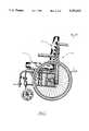
- FIG. 1is a side elevational view of a wheelchair with the anti-thrust seating system and the adjustable back system of the present invention.
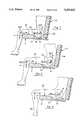
- FIG. 2is a view of the anti-thrust seating system of the present invention removed from the wheelchair.
- FIG. 3is a view of the anti-thrust seating system of FIG. 2 with the cover removed to show the base seating member and the fluid pad positioned on it.
- FIG. 4is an exploded view of the base seating member and fluid pad.
- FIG. 5is a cross-sectioned view taken along lines 5--5 of FIGS. 4 and 6.
- FIG. 6is a top plan view of the base seating member of FIG. 5.
- FIG. 7is a cross-sectioned view showing a person properly positioned and fitted in a seating system.
- FIG. 8is a view similar to FIG. 7 showing a person either who has grown from the size of FIG. 7 or who is otherwise improperly positioned and fitted in a seating system.
- FIG. 9illustrates the tendency of a person improperly fitted as in FIG. 8 to thrust or scoot forward into an undesirable position.
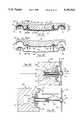
- FIG. 10illustrates a pre-ischial shelf extender or separate step means according to the present invention.
- FIG. 11is a view taken along line 11--11 of FIG. 10.
- FIG. 12is a top plan view of the pre-ischial shelf extender or separate step means of the present invention in place on the base seating member.
- FIG. 13is a view similar to FIGS. 8 and 9 showing the pre-ischial shelf extender or separate step means in place to properly position and fit the person of FIGS. 8 and 9 in the seating system.
- FIG. 14is a view similar to FIG. 7 showing a fluid pad on the base seating member.
- FIG. 15is a top plan view of the fluid pad.
- FIG. 16is a cross-sectional view similar to FIG. 13 showing the fluid pad positioned over the base seating member and pre-ischial shelf extender or separate step means.
- FIG. 17is a view similar to FIG. 16 showing the use of two, pre-ischial shelf extenders.
- FIG. 18is a perspective view of an additional thigh supporting member or cushion.
- FIG. 19illustrates the additional thigh supporting member in use with a pre-ischial shelf extender or separate step means of the present invention and a fluid pad.
- FIG. 20is a view similar to FIG. 17 but showing the use of a modified pre-ischial shelf extender that includes a raised bump portion.
- FIG. 21is a view similar to FIG. 20 showing the versatility of placing the shelf extender with the raised bump portion ahead of a shelf extender with a relatively flat top to position the bump as desired.
- FIG. 22is a view similar to FIGS. 20 and 21 showing the use of a single shelf extender with a raised bump potion.
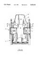
- FIG. 23is a perspective view of the adjustable, low profile back system of the present invention positioned on the back posts of the wheelchair.
- FIG. 24is a view of the adjustable back system of FIG. 23 with the cover removed and showing the back system in its forward or extended position.
- FIG. 25is an exploded view of the back system of FIG. 24.
- FIG. 26is a rear view of the back system taken along line 26--26 of FIG. 1.
- FIG. 27is a simplified view taken along line 27--27 of FIG. 26 showing the relatively rigid shell members of the back system in their low profile, retracted position.
- FIG. 28is a view similar to FIG. 27 showing the shell members in an extended position.
- FIG. 29is a view taken along line 29--29 of FIG. 27 showing one of the screw arrangements for moving the shell members in its retracted position.
- FIG. 30is a view taken along line 30--30 of FIG. 28 showing the screw arrangement of FIG. 29 in its extended position.
- FIGS. 31-35show various positions to which the front shell member and cushion can be adjusted to meet the needs of the user.
- the anti-thrust seating system 1 and adjustable back system 2 of the present inventionare primarily intended to be used in a wheelchair 3.
- the seating and back systemsare used together to properly position and support the user; however, they can be used separately if desired. They can also be used in other conveyance means such as a baby stroller.
- the seating system 1 as best seen in FIGS. 2-4includes an outer cover 5 (see FIG. 2) positioned over a base seating member 7 (see FIG. 3) and fluid pad 9.
- the base seating member 7is preferably a foam cushion but can be a relatively rigid tray. It can also be used in the present invention with or without the fluid pad 9 and even independently of the wheelchair 3.
- the base seating member 7 as shown in FIGS. 5 and 6has front and rear surfaces 11 and 13.
- the base seating member 7is then essentially divided into forward and rearward sections 15 and 17 which extend adjacent one another substantially from the front surface 11 to the rear surface 13 along the central axis 19.
- the forward section 15has an upper surface 21 which forms a shelf to receive and support the user's thighs (see FIG. 7).
- This surface 21 as best seen in FIG. 6extends substantially along and across the central axis 19.
- the rearward section 17, in turn,has an upper surface 23 forming a depressed, seating well to receive and support the user's buttocks including his or her ischial tuberosities 25 (see again FIG. 7).
- the upper surface 21is typically at an elevation above the upper surface 23 to produce increased support under the user's thighs and thus reduce that portion of the user's weight supported by the buttocks.
- the skin and tissue interface pressuresare thereby reduced at the sensitive bony prominences on the buttocks (i.e., ischial tuberosities, coccyx, and trochanters) and redistributed to underneath the thighs which generally can sustain higher tissue interface pressures.
- the upper surfaces 21 and 23 of the forward and rearward sections 15 and 17meet to form an upper edge 27.
- the upper edge 27extends substantially across the central axis 19 on each side of the base seating member 7.
- the upper surface or seating well 23 of the rearward section 17has two portions 29 and 31.
- the first portion 29 as best seen in FIG. 5extends or slopes downwardly and rearwardly at about 45 degrees from the upper edge 27. As shown, this is in an area immediately adjacent and rearward of the edge 27 wherein the first portion 29 serves to form a step face.
- the second portion 31 of the seating well 23extends rearwardly of the first portion 29 from the lower edge 33 that is formed by the meeting of the first and second portions 29 and 31 of the rearward surface 23.
- the step face 29 and surface 21 under the user's thighsform a shelf-step arrangement.
- This arrangementis positioned in front of the user's ischial tuberosities 25 wherein the step face 29 serves as a barrier (e.g., 1-4 inches high) to prevent undesirable forward thrust or movement of the user's ischial tuberosities 25. That is and referring to FIG. 8, if the user is a growing child for example, his or her thigh or femur bones 35 will grow significantly from the position of FIG. 7 to the position of FIG. 8. In doing so, the growing child unintentionally and undesirably alters and actually destroys the proper fit of FIG. 7. In the proper fit position of FIG.
- the backs of the child's kneesare adjacent and preferably touching the front surface 11 of the base seating member 7.
- His or her ischial tuberosities 25are then positioned near or immediately adjacent the step face 29 of the pre-ischial shelf formed by step face 29 and upper surface 21 with the flesh immediately ahead of the ischial tuberosities 25 preferably pressed against the step face 29.
- the back 37 of the wheelchair in FIG. 8is commonly moved rearwardly from its substantially vertical position of FIG. 7.
- the base seating member 7is simply moved forwardly in the wheelchair.
- the end result particularly with childrenis that the child thrusts or scoots forward (see FIG.
- a separate step member 41is provided as shown in FIGS. 10-13.
- the separate step means or member 41 as illustratedhas a second step face 29'.
- the separate step member 41can be removably positioned (e.g., by hook and loop fasteners 43) immediately adjacent and rearwardly of the first step face 29. In doing so, it effectively serves to extend the first step face 29 rearwardly to the position of step face 29' in FIG. 13. In this manner, the first anti-thrust barrier formed by the first step face 29 is also effectively moved rearwardly to form a second anti-thrust barrier.
- the user of FIGS. 8 and 9can then be properly fitted and supported in the desired position of FIG. 13.
- the separate step member or means 41is preferably dimensioned to conform to the step face 29 and to extend laterally across the central axis 19 of the base seating member 7 for a distance at least equal to the distance between the user's ischial tuberosities 25 (e.g., about 3 to 8 inches).
- the second step face 29'then slopes downwardly and rearwardly at about the same angle as the first step face 29 (e.g., about 45 degrees).
- the separate step member 41has an upper surface 21' (see FIG. 13) substantially aligning in use with the upper surface 21 of the forward section 15. In this manner, the surface 21' serves to effectively extend rearwardly the thigh supporting surface or shelf 21.
- the separate step member 41 and in particular, its upper surface 21'thus serves to form a pre-ischial shelf extender to better fit the user.
- the conforming separate step member 41serves to effectively extend rearwardly the original upper edge 27 to the new position of 27' in FIG. 13. It also effectively extends rearwardly the lower edge 33 to the new position of 33' in FIG. 13.
- the user's ischial tuberosities 25are preferably positioned immediately adjacent and rearward of the lower edge 33 so as to be close to but not in front of the lower edge 33 (in the configuration of FIG. 7) and of the lower edge 33' (in the configuration of FIG. 13).
- the ischial tuberosities 25preferably are near or immediately adjacent the step face or anti-thrust barrier 29 in FIG. 7 and the second face step or anti-thrust barrier 29' in FIG. 13 for proper fits with the flesh immediately ahead of the ischial tuberosities 25 preferably pressed against the respective step face 29 or 29'.
- the base seating member 7 and the pre-ischial shelf extender or separate step member 41can be used with or without an overlying fluid pad 9.
- the fluid pad 9is preferably designed so that the central pouches 45 (see FIG. 15) are always positioned over the base seating member 7 with the front seams 47 of the pouches 45 (see FIG. 14) forward of the edge 27.
- the pouches 45are preferably dimensioned so that their rear seams 49 are rearward of the lower edge 33 as well as rearward of the user's ischial tuberosities 25.
- the thigh and fluid pad supporting surface or shelf 21may be extended upwardly and rearwardly to the position of 21" in FIG. 19.
- thisis accomplished by fashioning the cushion 7' of FIG. 18 in the general shape of the upper support surface or shelf 21 and the extended shelf surface 21'.
- the extra cushion 7'can then be placed over both the surfaces 21 and 21' as shown in FIG. 19. This effectively raises the edge 27' in FIG. 16 to the position of edge 27'" in FIG. 19. It also shifts more weight load to the thigh supporting surface 21" particularly if the footrests are left in place.
- the legswill leverage the ischial tuberosities 25 and coccyx up higher in the seating well 23 and will reduce the pressure on these bony prominences.
- the extra cushion 7'is desirable for use with children and adults with pelvic obliquities (i.e., one hip is lower than the other).
- the separate cushion 7'can be used with the base seating member 7 without the pre-ischial shelf extender 41.
- the size and shape of the separate cushion 7'are substantially the same as the upper surface 21 of the forward section 15.
- the base seating member 7 and separate base member 7'may be used with or without a fluid pad 9.
- Removable accessories which are normally used on the upper surface of the seating member, such as abductors or adductors,can be placed on top of the separate base member 7' to further position the legs.
- the separate base seating member 7'may also be used when a pelvic obliquity accessory is used in the bottom of the seating well 23.
- the pelvic obliquity build-upis used in one side of the seating well 23 to compensate for a tilted pelvis. However, this lifts the whole pelvis somewhat higher than it would be without this accessory.
- the separate base member 7'can be used to raise the thighs correspondingly.
- the front seams 47 of the pouches 45are also positioned forwardly of the edges 27 and 28.
- the modified step member 41" as shownincludes a raised bump portion with a convex upper surface 21'". Because this step member 41" is a separate, removable member, it can be positioned as desired alone or with other step members 41 and 41' (see FIGS. 20-22) to selectively position its bump portion 21'" relative to the user.
- the bump portion 21'"extends laterally across the base seating member 7 and serves essentially as a fulcrum. In this manner, the weight of the user's legs actually leverages the person's weight off the ischial tuberosities 25 to effectively reduce the ischial pressure.
- this bump portion or fulcrum 21'"is best positioned rearwardly (see FIGS. 20 and 22). With other users, it may be best positioned in the sandwiched arrangement of FIG. 21 in between the substantially horizontally aligned, upper surfaces 21 and 21' of members 7 and 41'. In this manner, the raised bump portion 21'" can be custom fit to the user's needs.
- the forward edge 28 of the modified step member 41" in the arrangements of FIGS. 21 and 22is actually forward of the upper edge 27 of the base seating member 7. In the arrangement of FIG. 22, the lower edge 33" is then rearward of the lower edge 33 of the base seating cushion 7.
- FIGS. 14-22can be used with or without the overlying fluid pad 9.
- the fluid pad 9its front seams 47 of central pouches 45 are still preferably positioned as shown (i.e., forward of the extended upper edges 27', 27"and 27'" as well as forward of the original edge 27 and edge 28 of member 41").
- the pouches 45are preferably dimensioned so that their rear seams 49 are always positioned rearwardly of the user's ischial tuberosities 25. In this manner, no lateral seams such as 47 or 49 are positioned over the step face 29 in the configuration of FIG. 14 or over the second or third step faces 29' or 29" in the configurations of FIGS. 16 and 17 or over step face 29'" in the configuration of FIG. 20.
- the fluid pad 9preferably has additional pouches 45' both forward and rearward of the central or step pouches 45.
- the fluid pad 9 with such additional pouches 45'is still preferably dimensioned to position the front seams 47 of the central pouches 45 immediately adjacent and forward of the edge 27 in the respective configurations of FIGS. 14, 16, 17, and 19.
- the front seams 47are preferably positioned substantially closer to the upper edge 27 than to the front surface 11 of the base seating member 7. These laterally extending seams 47 aid in keeping or trapping fluid in the forward pouches 45' in front of the seams 47 for proper support of the thighs.
- the rear seams 49 of the central or step pouches 45are positioned at least in the configurations of FIGS.
- a longitudinal, central seam such as 51 in FIG. 15can also be provided for additional side-to-side stability.
- the purpose of this seam 51is to prevent the fluid from migrating to one side and causing a pelvic obliquity (i.e., one hip lower than the other) with a resulting scoliosis of the spine.
- its alignment with the central axis 19 of the base seating member 7will place the seam 51 between the halves of the user's buttocks where bottoming out is not usually a problem.
- the fluid in the fluid pad 9is preferably a high viscosity liquid but can be a gas, water, or other fluid if desired.
- the adjustable back system 2 of the present inventionhas been specially designed to provide a low profile with minimum seat depth loss in its retracted position and to offer substantial forward adjustments about multiple axes in its extended positions.
- the back system 2(see FIG. 23) includes an outer cover 4 as well as a mating pair of relatively rigid shell members 6 and 8 (see FIGS. 24 and 25) and back cushion 10 shown with a fluid spinal pad 12.
- the cover 4extends over the pad 12 and cushion 10 and can additionally extend over portions of the forward shell member 8.
- brackets 14(see FIG. 26) are first secured by screws 16 to the upright back posts 18 of the wheelchair 3 at the desired height.
- the wing laches 20(see FIG. 25) of the rearward shell member 6 are then swung about the back posts 18 within the brackets 14 (see FIG. 26) and removably secured in place by twist locks 22.
- the first and second shell members 6 and 8 as shown in FIGS. 25 and 27-28are designed so that the contours of the front surface 24 of the shell member 6 and the back surface 26 of the shell member 8 substantially match and mate or nest with one another in the retracted position of FIG. 27.
- the cushion 10is attached to the shell member 8 (e.g., preferably by hook and loop fasteners 43) wherein the back surface 30 of the foam cushion 10 is preferably shaped to match and substantially mate or nest against the front surface 28 of the shell member 8.
- all of the surfaces 24, 26, 28, and 30are preferably nested as shown in FIG. 27 and extending substantially between and along the back posts 18.
- the foam cushion 10is molded or cut to include depressions 32 (see FIGS. 27 and 28). These depressions 32 in the back surface 30 of the cushion 10 as shown in FIG. 27 are dimensioned to receive the forward end portions 34 of the screw arrangements 36 when the screw arrangements 36 are in their fully retracted positions. In these positions, the forward end portions 34 of the screw arrangements 36 pass through and project forwardly of the front surface 28 of the shell member 8 and into the depressions 32 in the cushion 10. More specifically, the first rigid shell member 6 as shown in FIGS. 27 and 28 is mounted with its C-shaped, wing portions 40 about the back posts 18 and its first or central portion 42 extending substantially between and along the back posts 18.
- the second shell member 8is then mounted by screw arrangements 36 to the first or central portion 42 of the shell member 6.
- the screw arrangements 36can then be selectively operated to move the second shell member 8 relative to the first shell member 6 and back posts 18 about multiple axes.
- Each screw arrangement 36 as best seen in FIGS. 29 and 30includes first and second telescoping screw members 44 and 46. These screw members 44 and 46 are mounted to be selectively moved relative to each other along the axis 48.
- the rearward end portion 50 of each screw arrangement 36is spherical and mounted within a spherical bearing 52 to the rear shell member 6.
- the screw head 54can be turned as desired to selectively extend and retract the telescoping screw members 44 and 46.
- the forward or second end portion 34 of the screw arrangement 36moves within and relative to the nut 56 which is fixed relative to the forward shell member 8.
- the nut 56in turn helps maintain the screw members 44 and 46 aligned horizontally.
- each of the screw arrangements 36By selectively operating each of the four screw arrangements 36 by turning the screw heads 54 (see FIG. 26), the forward shell member 8 and cushion 10 can be moved from the retracted position of FIGS. 27 and 31 with the shell surfaces 24 and 26 substantially adjacent or abutting each other to any number of extended positions including those of FIGS. 32-35.
- each of the screw arrangements 36has been extended its maximum distance (e.g., 2 to 3 or more inches).
- the back surface 26 of the shell member 8is maintained essentially in the same substantially vertical position as in its retracted position of FIG. 31. It is also moved essentially along a substantially horizontal axis 48' which is substantially parallel to the axes 48 of the screw arrangements 36 and substantially perpendicular to the surface 24 of the rear shell member 6.
- the back surface 26 of shell member 8can be inclined forwardly. Such inclination relative to, for example, a vertical plane extending through the upright, vertical back posts 18 of the wheelchair could be at 20 or so degrees. This inclination would be essentially about a horizontal axis through such a reference vertical plane.
- the back surface 26can be inclined rearwardly (e.g., 20 or so degrees about a horizonal axis in the reference vertical plane).
- the screw arrangements 36in differing amounts as shown in the top plan view of FIG. 35, the back surface 26 can be inclined laterally about a vertical axis substantially in the reference vertical plane.
- the selective extension of the four screw arrangements 36 in varying amountsenables the back cushion 10 to be positioned in a wide range of positions as a result of manipulating the back surface 26 of the shell member 8 about the above-mentioned multiple axes. Such manipulation can be done simultaneously or sequentially to properly fit and support the user on the seat 1 against the back 2.
- the relatively rigid shell member 8can be made of a material (e.g., plastic) that has some give or flex to it to further enable the shell member 8 to be positioned as desired by manipulation of the screw arrangements 36. As disclosed in FIG.
- the back system 2preferably uses four screw arrangements 36 located essentially at the corners of a quadrilateral figure (e.g., rectangle); however, a fewer or greater number of screw arrangements 36 could be used as desired. Additionally, the back system 2 can be removed from the wheelchair 3 by simply twisting the locks 22 to free the wing portions 20. Once so removed, the screw arrangements 36 maintain the front shell member 8 and cushion 10 in whatever position they were relative to the rear shell member 6. That is, the attaching means at 20 and the shell moving means at 36 operate independently of each other.
- the rear shell member 6can then be re-attached by wing portions 20 and twist locks 22 to the upright back posts 18 wherein the front shell member 8 and cushion 10 will be automatically returned to their previously set, desired position relative to the seat 1 and back posts 18.
Landscapes
- Health & Medical Sciences (AREA)
- Life Sciences & Earth Sciences (AREA)
- Animal Behavior & Ethology (AREA)
- General Health & Medical Sciences (AREA)
- Public Health (AREA)
- Veterinary Medicine (AREA)
- Nursing (AREA)
- Chair Legs, Seat Parts, And Backrests (AREA)
- Mattresses And Other Support Structures For Chairs And Beds (AREA)
- Orthopedics, Nursing, And Contraception (AREA)
Abstract
Description
Claims (54)
Priority Applications (12)
| Application Number | Priority Date | Filing Date | Title |
|---|---|---|---|
| US07/945,733US5352023A (en) | 1992-09-16 | 1992-09-16 | Seating and back systems for a wheelchair |
| EP93920505AEP0725584B1 (en) | 1992-09-16 | 1993-09-09 | Seating and back systems for a wheelchair |
| ES93920505TES2153843T3 (en) | 1992-09-16 | 1993-09-09 | SEAT AND BACKUP SYSTEMS FOR WHEELCHAIR. |
| DK93920505TDK0725584T3 (en) | 1992-09-16 | 1993-09-09 | Seat and back system for a wheelchair |
| CA002144630ACA2144630C (en) | 1992-09-16 | 1993-09-09 | Seating and back systems for a wheelchair |
| HK98113426.0AHK1012218B (en) | 1992-09-16 | 1993-09-09 | Seating and back systems for a wheelchair |
| PCT/US1993/008478WO1994006325A1 (en) | 1992-09-16 | 1993-09-09 | Seating and back systems for a wheelchair |
| US08/217,366US5524971A (en) | 1992-09-16 | 1994-03-24 | Seating and back systems for a wheelchair |
| US08/316,732US5490299A (en) | 1992-09-16 | 1994-10-03 | Seating system with pressure relieving fluid pad |
| US08/601,428US5592707A (en) | 1992-09-16 | 1996-02-12 | Seating system with pressure relieving pad |
| US08/632,898US5671977A (en) | 1992-09-16 | 1996-04-16 | Seating and back systems for a wheelchair |
| US08/633,158US5647637A (en) | 1992-09-16 | 1996-04-16 | Seating and back systems for a wheelchair |
Applications Claiming Priority (1)
| Application Number | Priority Date | Filing Date | Title |
|---|---|---|---|
| US07/945,733US5352023A (en) | 1992-09-16 | 1992-09-16 | Seating and back systems for a wheelchair |
Related Child Applications (2)
| Application Number | Title | Priority Date | Filing Date |
|---|---|---|---|
| US08/217,366ContinuationUS5524971A (en) | 1992-09-16 | 1994-03-24 | Seating and back systems for a wheelchair |
| US08/217,366DivisionUS5524971A (en) | 1992-09-16 | 1994-03-24 | Seating and back systems for a wheelchair |
Publications (1)
| Publication Number | Publication Date |
|---|---|
| US5352023Atrue US5352023A (en) | 1994-10-04 |
Family
ID=25483474
Family Applications (4)
| Application Number | Title | Priority Date | Filing Date |
|---|---|---|---|
| US07/945,733Expired - LifetimeUS5352023A (en) | 1992-09-16 | 1992-09-16 | Seating and back systems for a wheelchair |
| US08/217,366Expired - Fee RelatedUS5524971A (en) | 1992-09-16 | 1994-03-24 | Seating and back systems for a wheelchair |
| US08/632,898Expired - LifetimeUS5671977A (en) | 1992-09-16 | 1996-04-16 | Seating and back systems for a wheelchair |
| US08/633,158Expired - Fee RelatedUS5647637A (en) | 1992-09-16 | 1996-04-16 | Seating and back systems for a wheelchair |
Family Applications After (3)
| Application Number | Title | Priority Date | Filing Date |
|---|---|---|---|
| US08/217,366Expired - Fee RelatedUS5524971A (en) | 1992-09-16 | 1994-03-24 | Seating and back systems for a wheelchair |
| US08/632,898Expired - LifetimeUS5671977A (en) | 1992-09-16 | 1996-04-16 | Seating and back systems for a wheelchair |
| US08/633,158Expired - Fee RelatedUS5647637A (en) | 1992-09-16 | 1996-04-16 | Seating and back systems for a wheelchair |
Country Status (5)
| Country | Link |
|---|---|
| US (4) | US5352023A (en) |
| EP (1) | EP0725584B1 (en) |
| DK (1) | DK0725584T3 (en) |
| ES (1) | ES2153843T3 (en) |
| WO (1) | WO1994006325A1 (en) |
Cited By (69)
| Publication number | Priority date | Publication date | Assignee | Title |
|---|---|---|---|---|
| US5442823A (en)* | 1993-01-06 | 1995-08-22 | Invacare Corporation | Wheelchair cushion utilizing foams of different stiffnesses |
| US5490299A (en)* | 1992-09-16 | 1996-02-13 | Jay Medical Ltd. | Seating system with pressure relieving fluid pad |
| USD367199S (en) | 1994-11-04 | 1996-02-20 | Graebe Robert H | Foam base with flat pommel area |
| USD367198S (en) | 1994-10-20 | 1996-02-20 | Wolf Andrew W | Therapeutic seating cushion |
| US5551107A (en)* | 1992-02-20 | 1996-09-03 | Graebe; Robert H. | Modular cushion construction with detachable pommel, having a cover with front and rear openings |
| US5647637A (en)* | 1992-09-16 | 1997-07-15 | Jay Medical Ltd. | Seating and back systems for a wheelchair |
| WO1997045039A1 (en)* | 1996-05-28 | 1997-12-04 | Sunrise Medical Hhg Inc. | Wheelchair seat assembly with contoured seat pan and cushion and method |
| US5829081A (en) | 1993-11-09 | 1998-11-03 | Teksource, Lc | Cushioning device formed from separate reshapable cells |
| USD402789S (en) | 1997-08-29 | 1998-12-22 | Dennis J Detrie | Cheese stadium seat |
| USD404890S (en)* | 1997-09-26 | 1999-02-02 | Rhonda Monahan | Apple simulating seat cushion |
| USD405588S (en) | 1997-07-22 | 1999-02-16 | Wall Weldon T | Seat cushion |
| US5881409A (en) | 1993-06-22 | 1999-03-16 | Teksource, Ll | Puff-quilted bladders for containing flowable cushioning medium |
| USD413750S (en)* | 1998-04-28 | 1999-09-14 | Invacare Corporation | Fluid filled pressure compensation pad for use in a seat cushion |
| US5950263A (en)* | 1996-11-12 | 1999-09-14 | Sunrise Medical Hhg Inc. | Length extender for child's wheelchair seating system |
| US5954402A (en)* | 1997-04-28 | 1999-09-21 | Crown Therapeutics, Inc. | Size-adjustable load supporting device for wheelchairs |
| US5984418A (en)* | 1997-04-28 | 1999-11-16 | Crown Therapeutics, Inc. | Adjustable seat for wheelchairs |
| WO1999062379A1 (en)* | 1998-05-15 | 1999-12-09 | Mercado Medic Ab | Improvements in or relating to a chair |
| US6003949A (en)* | 1995-09-21 | 1999-12-21 | Rinne; Tommi | Chair seat cushion and chair seat with such a cushion |
| US6009578A (en)* | 1998-10-08 | 2000-01-04 | Davis; Steve | Seat cushion |
| US6020055A (en) | 1993-06-22 | 2000-02-01 | Teksource, Lc | Cushioning media including lubricated spherical objects |
| US6026527A (en) | 1996-02-14 | 2000-02-22 | Edizone, Lc | Gelatinous cushions with buckling columns |
| USD423859S (en)* | 1998-04-08 | 2000-05-02 | Friedrich Wolff AG | Medical therapy cushion |
| US6059370A (en)* | 1997-09-19 | 2000-05-09 | Sunrise Medical Hhg Inc. | Wheelchair seat back pelvic support system |
| US6095611A (en)* | 1997-10-07 | 2000-08-01 | Roho, Inc. | Modular backrest system for a wheelchair |
| US6142573A (en)* | 1995-09-18 | 2000-11-07 | Everest & Jennings Canadian Limited | Cushion element for use in a wheelchair |
| US6256819B1 (en)* | 1997-01-22 | 2001-07-10 | Span-America Medical Systems, Inc. | Multi-section positioning wheelchair cushion |
| US6378947B1 (en) | 1999-04-12 | 2002-04-30 | Bloorview Macmillan Centre | Seating system |
| USD463701S1 (en) | 2001-10-19 | 2002-10-01 | Roho, Incorporated | Seat cushion |
| US6474743B1 (en) | 2000-09-18 | 2002-11-05 | Crown Therapeutics, Inc. | Wheelchair back support assembly |
| US20040041449A1 (en)* | 2002-05-24 | 2004-03-04 | Bluhm Susan M. | Wheelchair slip cover |
| US20040245837A1 (en)* | 2003-06-03 | 2004-12-09 | Gerard Clifford | Seating device |
| US20050017565A1 (en)* | 2003-07-22 | 2005-01-27 | Sprouse Anthony Eric | Office chair with inflatable cellular insert |
| US20050022306A1 (en)* | 2003-07-28 | 2005-02-03 | Hetzel Thomas R. | Reinforced and adjustable contoured seat cushion and method of reinforcing and adjusting the contoured seat cushion |
| US20050022305A1 (en)* | 2003-07-28 | 2005-02-03 | Bieganek Joseph S. | Contoured seat cushion and method for offloading pressure from skeletal bone prominences and encouraging proper postural alignment |
| US20050022406A1 (en)* | 2003-07-28 | 2005-02-03 | Bieganek Joseph S. | Apparatus and method for evaluating clearance from a contoured seat cushion |
| US6893087B2 (en)* | 2002-11-18 | 2005-05-17 | Stearns Inc. | All terrain vehicle seat cushion |
| US6901617B2 (en) | 2002-05-06 | 2005-06-07 | Roho, Inc. | Multi-layer cushion and cover |
| US20050151410A1 (en)* | 2003-07-22 | 2005-07-14 | Sprouse Anthony E.Ii | Chair with inflatable cellular insert |
| US20050200187A1 (en)* | 2004-03-05 | 2005-09-15 | Ravelex S.A. | Preventive seat and prophylactic and method thereof |
| US20050225140A1 (en)* | 2002-05-24 | 2005-10-13 | Savvy Physiotherapy Pty Ltd | Seating arrangement |
| US20050235423A1 (en)* | 2003-07-28 | 2005-10-27 | Hetzel Thomas R | Seat cushion with adjustable contour and method of adjusting the contour of a seat cushion |
| US20050275256A1 (en)* | 2002-12-06 | 2005-12-15 | Hilliard Geoffrey G | Seat cushion |
| US20060170274A1 (en)* | 2003-06-30 | 2006-08-03 | Moule Terry G | Seat portion of a seat |
| US20070096534A1 (en)* | 2003-06-25 | 2007-05-03 | Davidson Jennifer A | Chair |
| US7220376B2 (en) | 2003-07-28 | 2007-05-22 | Aspen Seating, Llc | Individually-contoured seat cushion and shape capturing and fabricating method for seat cushion |
| US20080079306A1 (en)* | 2006-09-29 | 2008-04-03 | Sunrise Medical Hhg Inc. | Wheelchair seat cushion |
| US20100132120A1 (en)* | 2008-12-02 | 2010-06-03 | Sunrise Medical Hhg, Inc. | Adaptive Seat Cushion Having A Pressure-Relieving Structure |
| US20100187791A1 (en)* | 2009-01-23 | 2010-07-29 | Izinger Maayan | Seat cushion |
| US20110277909A1 (en)* | 2009-02-13 | 2011-11-17 | Maurizio Vecchiola | Seat element moulded from expandable and retriculable polyolefin material |
| US8075981B2 (en) | 2007-08-23 | 2011-12-13 | Edizone, Llc | Alternating pattern gel cushioning elements and related methods |
| EP1787549B1 (en)* | 2005-11-18 | 2013-01-16 | Sponsor S.r.L. | Sitting cushion with improved comfort |
| US20130060282A1 (en)* | 2011-09-03 | 2013-03-07 | Loan Kim Thi Pham | Orthopedic chair for treatment and prevention of spinal diseases |
| US8424137B1 (en) | 2007-11-27 | 2013-04-23 | Edizone, Llc | Ribbed gel |
| US8434748B1 (en) | 2007-10-03 | 2013-05-07 | Edizone, Llc | Cushions comprising gel springs |
| US20130214583A1 (en)* | 2012-02-22 | 2013-08-22 | Toyobo Co., Ltd. | Cushion pad for car seat |
| US20130285432A1 (en)* | 2012-04-30 | 2013-10-31 | Adams Mfg. Corp. | Seat for Molded Plastic Chairs |
| US8584286B2 (en) | 2010-04-27 | 2013-11-19 | Ec Service Inc. | Systems and methods for providing a self deflating cushion |
| US8628067B2 (en) | 2008-10-03 | 2014-01-14 | Edizone, Llc | Cushions comprising core structures and related methods |
| US20140077550A1 (en)* | 2012-09-14 | 2014-03-20 | Toyota Boshoku Kabushiki Kaisha | Vehicle seat |
| US8932692B2 (en) | 2008-10-03 | 2015-01-13 | Edizone, Llc | Cushions comprising deformable members and related methods |
| US20150015050A1 (en)* | 2013-02-25 | 2015-01-15 | Carol N. Van Zandt | Seat Cushion |
| US9289069B2 (en) | 2012-04-30 | 2016-03-22 | Adams Mfg. Corp. | Seat for molded plastic chairs |
| JP2017042385A (en)* | 2015-08-27 | 2017-03-02 | 株式会社ライオン事務器 | Seat tool buffer |
| WO2019168414A1 (en)* | 2018-02-27 | 2019-09-06 | Roger Thomas MASCULL and Elizabeth Jocelyn MASCULL as Trustees of the RT and EJ Family Trust | A seating support |
| US10555611B2 (en) | 2013-12-06 | 2020-02-11 | Force 3 Innovations Inc. | Adjustable seating systems and associated structures |
| US11382428B2 (en)* | 2020-10-02 | 2022-07-12 | Ergogenesis Workplace Solutions Llc | Office chair seat and method of making same |
| US20230414002A1 (en)* | 2021-07-14 | 2023-12-28 | Anthro Form, Llc | Seat configuration |
| US11857471B2 (en)* | 2020-07-30 | 2024-01-02 | Permobil, Inc. | Adjustable seat cushion |
| USD1073080S1 (en)* | 2020-12-17 | 2025-04-29 | Services Médicaux Georges Sioufi Inc. | Ergonomic seat |
Families Citing this family (66)
| Publication number | Priority date | Publication date | Assignee | Title |
|---|---|---|---|---|
| US5865504A (en)* | 1994-05-19 | 1999-02-02 | Skil-Care Corp. | Reclining backrest system for a person in a wheelchair |
| DE9416674U1 (en)* | 1994-10-18 | 1994-12-01 | Mathieu, Ernst-Ulrich, Dipl.-Ing., 55546 Frei-Laubersheim | Seating and training area |
| AUPM891294A0 (en) | 1994-10-19 | 1994-11-10 | Dixon, Barry James | Improvements to chairs |
| US6012188A (en)* | 1996-03-13 | 2000-01-11 | Ooltewah Manufacturing Company | Selectively deformable cushion |
| US6082824A (en)* | 1996-11-08 | 2000-07-04 | Chow; William W. | Therapeutic sling seat |
| US6032975A (en)* | 1996-11-12 | 2000-03-07 | Sunrise Medical Hhg Inc. | Ergonomic wheelchair seat |
| US5971417A (en)* | 1996-11-12 | 1999-10-26 | Sunrise Medical Hhg Inc. | Wheelchair with pivotal back rest |
| US6241319B1 (en) | 1997-04-29 | 2001-06-05 | SäRNMARK HJäLPMEDEL AB | Seat plate for wheel chairs |
| EP1194104A2 (en)* | 1997-04-29 | 2002-04-10 | Särnmark Hjälpmedel AB | Seat plate for wheel chairs |
| US5848824A (en)* | 1997-05-19 | 1998-12-15 | Mocur; Paul | Wheelchair seat and backrest construction |
| USD407353S (en) | 1997-10-06 | 1999-03-30 | Roho, Inc. | Back support for a wheelchair |
| USD413841S (en)* | 1997-10-06 | 1999-09-14 | Roho, Inc. | Back support pad assembly for a wheelchair |
| USD413085S (en) | 1997-10-06 | 1999-08-24 | Roho, Inc. | Back support pad assembly for a wheelchair |
| USD412685S (en) | 1997-10-06 | 1999-08-10 | Roho, Inc. | Back support pad assembly for a wheelchair |
| USD408767S (en) | 1997-10-06 | 1999-04-27 | Roho, Inc. | Back support for a wheelchair |
| US5933891A (en)* | 1998-04-24 | 1999-08-10 | Invacare Corporation | Wheelchair seating system including trapezoidally sectioned fluid bag |
| US7191482B2 (en) | 1998-05-06 | 2007-03-20 | Hill Rom Services, Inc. | Patient support |
| EP1076499B1 (en) | 1998-05-06 | 2004-07-21 | Hill-Rom Services, Inc. | Mattress or cushion structure |
| US9462893B2 (en) | 1998-05-06 | 2016-10-11 | Hill-Rom Services, Inc. | Cover system for a patient support surface |
| CA2289698C (en)* | 1998-05-18 | 2005-08-23 | Sarnmark Hjalpmedel Ab | Seat plate for wheel chairs |
| US6257664B1 (en) | 1998-11-16 | 2001-07-10 | Invacare Corporation | Multiple adjustable back assembly for use with wheelchair |
| US6135131A (en)* | 1998-12-23 | 2000-10-24 | Ez Way Inc. | Adjustable walker handles |
| US6086086A (en)* | 1999-05-11 | 2000-07-11 | Sunrise Medical Hhg Inc. | Stroller with tilt-in-space capability |
| US6135562A (en)* | 1999-09-10 | 2000-10-24 | Vittoria Infanti Valentine | Chair with releasably detachable and interchangeable cushions |
| DE50012765D1 (en)* | 1999-12-23 | 2006-06-22 | Keiper Recaro Gmbh Co | Vehicle seat, in particular motor vehicle seat |
| US6293616B1 (en)* | 2000-01-10 | 2001-09-25 | Ford Global Technologies, Inc. | Modular rail for roof and windshield |
| IT1317436B1 (en)* | 2000-04-28 | 2003-07-09 | Selle Italia Srl | SELLA STRUCTURE, PARTICULARLY DESIGNED FOR CYCLES |
| US6688693B2 (en)* | 2000-10-02 | 2004-02-10 | Sunrise Medical Hhg Inc. | Seat back assembly |
| AU2002220143A1 (en)* | 2000-11-01 | 2002-05-15 | Cascade Designs, Inc. | Adjustable quick release seatback system particularly for use with wheelchairs |
| US6502263B1 (en)* | 2001-07-26 | 2003-01-07 | Invacare Corporation | Seat cushion and positioning assembly including inflatable air cell pressure compensation insert |
| ES2224776A1 (en)* | 2002-01-21 | 2005-03-01 | Play, S.A. | Child pushchair |
| US6640367B2 (en)* | 2002-01-23 | 2003-11-04 | Chih-Yu Hsia | Pillows |
| US7651163B2 (en)* | 2002-12-02 | 2010-01-26 | Logicback, Inc. | Lumbar support device |
| US7040706B2 (en)* | 2002-12-09 | 2006-05-09 | Phat Cushion Llc | Seat and method of making same |
| FR2851524B1 (en)* | 2003-02-21 | 2005-05-06 | Faurecia Sieges Automobile | AUTOMOTIVE VEHICLE SEAT BACKREST. |
| US20050067861A1 (en)* | 2003-09-30 | 2005-03-31 | Eli Avihod | Wheelchair with book-style folding feature |
| US8157325B2 (en)* | 2003-12-30 | 2012-04-17 | Hni Technologies Inc. | Chair back rest with improved resilience and support |
| US20060091706A1 (en)* | 2004-10-22 | 2006-05-04 | Sunrise Medical Hhg Inc. | Seat assembly for wheelchair |
| USD549345S1 (en)* | 2005-12-08 | 2007-08-21 | Roger Mascull | Seat and base |
| US7585030B2 (en)* | 2006-07-20 | 2009-09-08 | Galbreath Ashford A | Environmentally friendly layered seating assembly |
| US7918510B2 (en)* | 2006-08-08 | 2011-04-05 | Van Den Nieuwboer Johanna Hendrika | Pathology related individual modular orthopedic seating system |
| USD565187S1 (en)* | 2006-11-20 | 2008-03-25 | Roger Thomas Mascull | Seat |
| CA2694291A1 (en)* | 2007-07-25 | 2009-01-29 | Roho, Inc. | Supportive back overlay for wheelchair back |
| JP4388575B2 (en)* | 2007-11-27 | 2009-12-24 | 本田技研工業株式会社 | Vehicle seat |
| DE112009000524T5 (en)* | 2008-03-05 | 2011-02-17 | Tamarack Habilitation Technologies, Inc., Blaine | seat cushion |
| US8991930B2 (en)* | 2008-09-22 | 2015-03-31 | Johnson Controls Technology Company | Closed cell foam vehicle interior component and method of making same |
| JP5277912B2 (en)* | 2008-11-28 | 2013-08-28 | トヨタ紡織株式会社 | Vehicle seat |
| JP5513212B2 (en)* | 2010-03-30 | 2014-06-04 | 日本発條株式会社 | Vehicle seat back and vehicle seat provided with the same |
| USD670109S1 (en)* | 2010-05-26 | 2012-11-06 | Pro Medicare S.R.L. | Postural system |
| US8602501B2 (en) | 2010-09-14 | 2013-12-10 | Herman Miller, Inc. | Backrest |
| US8973993B2 (en)* | 2011-05-06 | 2015-03-10 | Lme Inc. | Configurable cushion set for a seat |
| GB201112534D0 (en)* | 2011-07-21 | 2011-08-31 | Therrien Benoit Jr | Car seat riser for the lwoer part of the thighs |
| EP2564826B9 (en)* | 2011-08-29 | 2015-04-08 | Invacare International Sàrl | Backrest for wheelchair |
| US9132052B2 (en)* | 2012-04-12 | 2015-09-15 | Sage Products, Llc | Apparatus and method for positioning a seated patient |
| US9693920B2 (en) | 2013-11-27 | 2017-07-04 | Sage Products, Llc | Apparatus and system for turning and positioning a patient |
| US9504620B2 (en) | 2014-07-23 | 2016-11-29 | American Sterilizer Company | Method of controlling a pressurized mattress system for a support structure |
| US9849053B2 (en) | 2015-08-18 | 2017-12-26 | Sage Products, Llc | Apparatus and system for boosting, transferring, turning and positioning a patient |
| US10765576B2 (en) | 2015-08-18 | 2020-09-08 | Sage Products, Llc | Apparatus and system for boosting, transferring, turning and positioning a patient |
| WO2018232012A1 (en) | 2017-06-13 | 2018-12-20 | Sage Products, Llc | Patient positioning and support system |
| USD826795S1 (en)* | 2017-06-30 | 2018-08-28 | Solson Enterprises, Llc | Wheelchair |
| USD823174S1 (en)* | 2017-07-21 | 2018-07-17 | Oscar (Hk) International Limited | Wheelchair |
| USD856197S1 (en)* | 2017-08-29 | 2019-08-13 | Strongback, LLC | Wheelchair |
| US10667969B2 (en) | 2018-01-16 | 2020-06-02 | Kinetic Innovative Seating System Llc | Ergonomically designed seating apparatus |
| WO2020041493A1 (en) | 2018-08-21 | 2020-02-27 | Sage Products, Llc | Systems and methods for lifting and positioning a patient |
| CA3092701A1 (en)* | 2020-09-10 | 2022-03-10 | Thuja Innovations Inc. | Thermal comfort wheelchair backrest |
| US11890240B2 (en) | 2021-04-30 | 2024-02-06 | Sage Products, Llc | Method and device for turning and positioning a patient using fillable chambers |
Citations (15)
| Publication number | Priority date | Publication date | Assignee | Title |
|---|---|---|---|---|
| US4588229A (en)* | 1982-03-16 | 1986-05-13 | Jay Medical, Ltd. | Seat cushion |
| US4643481A (en)* | 1984-11-08 | 1987-02-17 | Saloff William S | Seat system for preventing decubiti |
| US4660238A (en)* | 1985-05-20 | 1987-04-28 | Jay Medical, Ltd. | Hemorrhoid seat cushion |
| US4728551A (en)* | 1987-02-24 | 1988-03-01 | Jay Eric C | Flowable pressure compensating fitting materials |
| US4761843A (en)* | 1985-05-20 | 1988-08-09 | Jay Medical, Ltd. | Hemorrhoid seat cushion |
| US4842330A (en)* | 1987-06-30 | 1989-06-27 | Jay Medical, Ltd. | Protective seat cushion |
| US4951334A (en)* | 1989-07-26 | 1990-08-28 | Maier Edmund K | Pressure relief cushion |
| US5018790A (en)* | 1988-07-20 | 1991-05-28 | Jay Medical, Ltd. | Customized seat cushion |
| US5062677A (en)* | 1988-11-16 | 1991-11-05 | Jay Medical, Ltd. | Wheelchair back system |
| US5074620A (en)* | 1989-09-05 | 1991-12-24 | Jay Medical, Ltd. | Wheelchair seat system |
| US5088747A (en)* | 1990-09-12 | 1992-02-18 | International Marketing And Design Seating System, Inc. | Wheelchair seating system |
| US5123699A (en)* | 1991-04-09 | 1992-06-23 | Warburton Patricia G | Portable, customized patient support system with detachable bottom back and side cushions and method of using |
| US5189747A (en)* | 1991-10-04 | 1993-03-02 | Canadian Posture And Seating Centre (1988) Inc. | Seat cushion |
| US5201780A (en)* | 1991-09-06 | 1993-04-13 | Jay Medical, Ltd. | Anti-decubitus mattress pad |
| USD335235S (en) | 1990-09-26 | 1993-05-04 | Biotech Ltd., Inc. | Wheelchair cushion |
Family Cites Families (17)
| Publication number | Priority date | Publication date | Assignee | Title |
|---|---|---|---|---|
| US1562658A (en)* | 1922-11-03 | 1925-11-24 | John F Presley | Vehicle seat |
| US1486813A (en)* | 1923-03-20 | 1924-03-11 | Tallman John Atlee | Chair |
| US1726939A (en)* | 1927-03-14 | 1929-09-03 | New York Rubber Corp | Pneumatic cushion |
| US1706794A (en)* | 1927-08-26 | 1929-03-26 | Iva B Linebarger | Adjustable back support |
| US2575764A (en)* | 1947-04-10 | 1951-11-20 | Hans G Morner | Air-filled upholstery and method of manufacture |
| US3112956A (en)* | 1961-08-30 | 1963-12-03 | Schick Melvin Edward | Inflatable seat and back rest |
| US3747978A (en)* | 1972-03-07 | 1973-07-24 | American Seating Co | Transit seat with contoured plastic shell |
| JPS6080805A (en)* | 1983-10-11 | 1985-05-08 | Takashi Mori | Artificial light source device |
| US5211446A (en)* | 1988-11-16 | 1993-05-18 | Jay Medical, Ltd. | Wheelchair back system |
| US5254404A (en)* | 1989-07-12 | 1993-10-19 | Fuji Photo Film Co., Ltd. | Magnetic recording medium comprising ferromagnetic particles having crystallite size of less than 450 angstroms and a specified polyurethane binder |
| US5064247A (en)* | 1990-05-23 | 1991-11-12 | Allsteel Inc. | Wire rod office furniture stacking chair |
| US5378045A (en)* | 1991-11-13 | 1995-01-03 | Invacare Corporation | Seat cushion for wheelchairs |
| US5297851A (en)* | 1991-12-05 | 1994-03-29 | Westinghouse Electric Corp. | Chair fastening device |
| US5317773A (en)* | 1992-02-20 | 1994-06-07 | Graebe Robert H | Waterblown foam base |
| US5352023A (en)* | 1992-09-16 | 1994-10-04 | Jay Medical, Ltd. | Seating and back systems for a wheelchair |
| US5395162A (en)* | 1993-02-16 | 1995-03-07 | Jay Medical Ltd. | Seating system |
| US5390384A (en)* | 1993-08-13 | 1995-02-21 | Jay Medical Ltd. | Self-adjusting seating system |
- 1992
- 1992-09-16USUS07/945,733patent/US5352023A/ennot_activeExpired - Lifetime
- 1993
- 1993-09-09EPEP93920505Apatent/EP0725584B1/ennot_activeExpired - Lifetime
- 1993-09-09DKDK93920505Tpatent/DK0725584T3/enactive
- 1993-09-09WOPCT/US1993/008478patent/WO1994006325A1/enactiveIP Right Grant
- 1993-09-09ESES93920505Tpatent/ES2153843T3/ennot_activeExpired - Lifetime
- 1994
- 1994-03-24USUS08/217,366patent/US5524971A/ennot_activeExpired - Fee Related
- 1996
- 1996-04-16USUS08/632,898patent/US5671977A/ennot_activeExpired - Lifetime
- 1996-04-16USUS08/633,158patent/US5647637A/ennot_activeExpired - Fee Related
Patent Citations (17)
| Publication number | Priority date | Publication date | Assignee | Title |
|---|---|---|---|---|
| US4588229A (en)* | 1982-03-16 | 1986-05-13 | Jay Medical, Ltd. | Seat cushion |
| US4726624A (en)* | 1982-03-16 | 1988-02-23 | Jay Medical, Ltd. | Seat cushion |
| US4726624B1 (en)* | 1982-03-16 | 1993-11-09 | Jay Medical, Ltd. | Seat cushion |
| US4643481A (en)* | 1984-11-08 | 1987-02-17 | Saloff William S | Seat system for preventing decubiti |
| US4660238A (en)* | 1985-05-20 | 1987-04-28 | Jay Medical, Ltd. | Hemorrhoid seat cushion |
| US4761843A (en)* | 1985-05-20 | 1988-08-09 | Jay Medical, Ltd. | Hemorrhoid seat cushion |
| US4728551A (en)* | 1987-02-24 | 1988-03-01 | Jay Eric C | Flowable pressure compensating fitting materials |
| US4842330A (en)* | 1987-06-30 | 1989-06-27 | Jay Medical, Ltd. | Protective seat cushion |
| US5018790A (en)* | 1988-07-20 | 1991-05-28 | Jay Medical, Ltd. | Customized seat cushion |
| US5062677A (en)* | 1988-11-16 | 1991-11-05 | Jay Medical, Ltd. | Wheelchair back system |
| US4951334A (en)* | 1989-07-26 | 1990-08-28 | Maier Edmund K | Pressure relief cushion |
| US5074620A (en)* | 1989-09-05 | 1991-12-24 | Jay Medical, Ltd. | Wheelchair seat system |
| US5088747A (en)* | 1990-09-12 | 1992-02-18 | International Marketing And Design Seating System, Inc. | Wheelchair seating system |
| USD335235S (en) | 1990-09-26 | 1993-05-04 | Biotech Ltd., Inc. | Wheelchair cushion |
| US5123699A (en)* | 1991-04-09 | 1992-06-23 | Warburton Patricia G | Portable, customized patient support system with detachable bottom back and side cushions and method of using |
| US5201780A (en)* | 1991-09-06 | 1993-04-13 | Jay Medical, Ltd. | Anti-decubitus mattress pad |
| US5189747A (en)* | 1991-10-04 | 1993-03-02 | Canadian Posture And Seating Centre (1988) Inc. | Seat cushion |
Non-Patent Citations (1)
| Title |
|---|
| Preston Corporation Brochure 1982.* |
Cited By (93)
| Publication number | Priority date | Publication date | Assignee | Title |
|---|---|---|---|---|
| US5613257A (en)* | 1992-02-20 | 1997-03-25 | Graebe; Robert H. | Modular cushion construction with detachable pommel |
| US5551107A (en)* | 1992-02-20 | 1996-09-03 | Graebe; Robert H. | Modular cushion construction with detachable pommel, having a cover with front and rear openings |
| US5490299A (en)* | 1992-09-16 | 1996-02-13 | Jay Medical Ltd. | Seating system with pressure relieving fluid pad |
| US5671977A (en)* | 1992-09-16 | 1997-09-30 | Jay Medical Ltd. | Seating and back systems for a wheelchair |
| US5647637A (en)* | 1992-09-16 | 1997-07-15 | Jay Medical Ltd. | Seating and back systems for a wheelchair |
| US5592707A (en)* | 1992-09-16 | 1997-01-14 | Jay Medical Ltd. | Seating system with pressure relieving pad |
| US5442823A (en)* | 1993-01-06 | 1995-08-22 | Invacare Corporation | Wheelchair cushion utilizing foams of different stiffnesses |
| US6020055A (en) | 1993-06-22 | 2000-02-01 | Teksource, Lc | Cushioning media including lubricated spherical objects |
| US6197099B1 (en) | 1993-06-22 | 2001-03-06 | Tony M. Pearce | Flowable cushioning media including lubricated spherical objects |
| US5881409A (en) | 1993-06-22 | 1999-03-16 | Teksource, Ll | Puff-quilted bladders for containing flowable cushioning medium |
| US5829081A (en) | 1993-11-09 | 1998-11-03 | Teksource, Lc | Cushioning device formed from separate reshapable cells |
| USD367198S (en) | 1994-10-20 | 1996-02-20 | Wolf Andrew W | Therapeutic seating cushion |
| USD367199S (en) | 1994-11-04 | 1996-02-20 | Graebe Robert H | Foam base with flat pommel area |
| US6142573A (en)* | 1995-09-18 | 2000-11-07 | Everest & Jennings Canadian Limited | Cushion element for use in a wheelchair |
| RU2171086C2 (en)* | 1995-09-21 | 2001-07-27 | Томми РИННЕ | Cushion for chair seat and chair seat with such cushion |
| US6003949A (en)* | 1995-09-21 | 1999-12-21 | Rinne; Tommi | Chair seat cushion and chair seat with such a cushion |
| EP1232702A2 (en) | 1995-09-21 | 2002-08-21 | Tommi Rinne | A chair seat cushion |
| US6026527A (en) | 1996-02-14 | 2000-02-22 | Edizone, Lc | Gelatinous cushions with buckling columns |
| US5857749A (en)* | 1996-05-28 | 1999-01-12 | Jay Medical Ltd. | Wheelchair seat assembly with contoured seat pan and cushion and method |
| US5836654A (en)* | 1996-05-28 | 1998-11-17 | Sunrise Medical Hhg Inc. | Wheelchair seat assembly with contoured seat pan and cushion and method |
| WO1997045039A1 (en)* | 1996-05-28 | 1997-12-04 | Sunrise Medical Hhg Inc. | Wheelchair seat assembly with contoured seat pan and cushion and method |
| US5950263A (en)* | 1996-11-12 | 1999-09-14 | Sunrise Medical Hhg Inc. | Length extender for child's wheelchair seating system |
| US6256819B1 (en)* | 1997-01-22 | 2001-07-10 | Span-America Medical Systems, Inc. | Multi-section positioning wheelchair cushion |
| US5954402A (en)* | 1997-04-28 | 1999-09-21 | Crown Therapeutics, Inc. | Size-adjustable load supporting device for wheelchairs |
| US5984418A (en)* | 1997-04-28 | 1999-11-16 | Crown Therapeutics, Inc. | Adjustable seat for wheelchairs |
| USD405588S (en) | 1997-07-22 | 1999-02-16 | Wall Weldon T | Seat cushion |
| USD402789S (en) | 1997-08-29 | 1998-12-22 | Dennis J Detrie | Cheese stadium seat |
| US6059370A (en)* | 1997-09-19 | 2000-05-09 | Sunrise Medical Hhg Inc. | Wheelchair seat back pelvic support system |
| USD404890S (en)* | 1997-09-26 | 1999-02-02 | Rhonda Monahan | Apple simulating seat cushion |
| US6095611A (en)* | 1997-10-07 | 2000-08-01 | Roho, Inc. | Modular backrest system for a wheelchair |
| USD423859S (en)* | 1998-04-08 | 2000-05-02 | Friedrich Wolff AG | Medical therapy cushion |
| USD413750S (en)* | 1998-04-28 | 1999-09-14 | Invacare Corporation | Fluid filled pressure compensation pad for use in a seat cushion |
| WO1999062379A1 (en)* | 1998-05-15 | 1999-12-09 | Mercado Medic Ab | Improvements in or relating to a chair |
| US6305751B1 (en) | 1998-05-15 | 2001-10-23 | Mercado Medic Ab | Chair |
| US6009578A (en)* | 1998-10-08 | 2000-01-04 | Davis; Steve | Seat cushion |
| US6378947B1 (en) | 1999-04-12 | 2002-04-30 | Bloorview Macmillan Centre | Seating system |
| US6474743B1 (en) | 2000-09-18 | 2002-11-05 | Crown Therapeutics, Inc. | Wheelchair back support assembly |
| USD463701S1 (en) | 2001-10-19 | 2002-10-01 | Roho, Incorporated | Seat cushion |
| US6901617B2 (en) | 2002-05-06 | 2005-06-07 | Roho, Inc. | Multi-layer cushion and cover |
| US20040041449A1 (en)* | 2002-05-24 | 2004-03-04 | Bluhm Susan M. | Wheelchair slip cover |
| US20050225140A1 (en)* | 2002-05-24 | 2005-10-13 | Savvy Physiotherapy Pty Ltd | Seating arrangement |
| US6893087B2 (en)* | 2002-11-18 | 2005-05-17 | Stearns Inc. | All terrain vehicle seat cushion |
| US20050275256A1 (en)* | 2002-12-06 | 2005-12-15 | Hilliard Geoffrey G | Seat cushion |
| US20040245837A1 (en)* | 2003-06-03 | 2004-12-09 | Gerard Clifford | Seating device |
| US7347498B2 (en)* | 2003-06-03 | 2008-03-25 | Gerard Clifford | Seating device |
| US7350869B2 (en)* | 2003-06-25 | 2008-04-01 | Jennifer Anne Davidson | Chair |
| US20070096534A1 (en)* | 2003-06-25 | 2007-05-03 | Davidson Jennifer A | Chair |
| US7445292B2 (en)* | 2003-06-30 | 2008-11-04 | Terry Glyn Moule | Seat portion of a seat |
| US20060170274A1 (en)* | 2003-06-30 | 2006-08-03 | Moule Terry G | Seat portion of a seat |
| US20050151410A1 (en)* | 2003-07-22 | 2005-07-14 | Sprouse Anthony E.Ii | Chair with inflatable cellular insert |
| US20050017565A1 (en)* | 2003-07-22 | 2005-01-27 | Sprouse Anthony Eric | Office chair with inflatable cellular insert |
| US20050022306A1 (en)* | 2003-07-28 | 2005-02-03 | Hetzel Thomas R. | Reinforced and adjustable contoured seat cushion and method of reinforcing and adjusting the contoured seat cushion |
| US6990744B2 (en) | 2003-07-28 | 2006-01-31 | Aspen Seating, Llc | Apparatus and method for evaluating clearance from a contoured seat cushion |
| US7140057B2 (en) | 2003-07-28 | 2006-11-28 | Aspen Seating, Llc | Reinforced and adjustable contoured seat cushion and method of reinforcing and adjusting the contoured seat cushion |
| US20050022406A1 (en)* | 2003-07-28 | 2005-02-03 | Bieganek Joseph S. | Apparatus and method for evaluating clearance from a contoured seat cushion |
| US7216388B2 (en) | 2003-07-28 | 2007-05-15 | Aspen Seating, Llc | Contoured seat cushion and method for offloading pressure from skeletal bone prominences and encouraging proper postural alignment |
| US7220376B2 (en) | 2003-07-28 | 2007-05-22 | Aspen Seating, Llc | Individually-contoured seat cushion and shape capturing and fabricating method for seat cushion |
| US20050235423A1 (en)* | 2003-07-28 | 2005-10-27 | Hetzel Thomas R | Seat cushion with adjustable contour and method of adjusting the contour of a seat cushion |
| US7373678B2 (en) | 2003-07-28 | 2008-05-20 | Aspen Seating, Llc | Seat cushion with adjustable contour and method of adjusting the contour of a seat cushion |
| US20050022305A1 (en)* | 2003-07-28 | 2005-02-03 | Bieganek Joseph S. | Contoured seat cushion and method for offloading pressure from skeletal bone prominences and encouraging proper postural alignment |
| US20050200187A1 (en)* | 2004-03-05 | 2005-09-15 | Ravelex S.A. | Preventive seat and prophylactic and method thereof |
| EP1787549B1 (en)* | 2005-11-18 | 2013-01-16 | Sponsor S.r.L. | Sitting cushion with improved comfort |
| US20080079306A1 (en)* | 2006-09-29 | 2008-04-03 | Sunrise Medical Hhg Inc. | Wheelchair seat cushion |
| US7614704B2 (en) | 2006-09-29 | 2009-11-10 | Sunrise Medical Hhg Inc. | Wheelchair seat cushion |
| US8075981B2 (en) | 2007-08-23 | 2011-12-13 | Edizone, Llc | Alternating pattern gel cushioning elements and related methods |
| US8434748B1 (en) | 2007-10-03 | 2013-05-07 | Edizone, Llc | Cushions comprising gel springs |
| US8424137B1 (en) | 2007-11-27 | 2013-04-23 | Edizone, Llc | Ribbed gel |
| US8932692B2 (en) | 2008-10-03 | 2015-01-13 | Edizone, Llc | Cushions comprising deformable members and related methods |
| US8628067B2 (en) | 2008-10-03 | 2014-01-14 | Edizone, Llc | Cushions comprising core structures and related methods |
| US20100132120A1 (en)* | 2008-12-02 | 2010-06-03 | Sunrise Medical Hhg, Inc. | Adaptive Seat Cushion Having A Pressure-Relieving Structure |
| US20100187791A1 (en)* | 2009-01-23 | 2010-07-29 | Izinger Maayan | Seat cushion |
| US8167326B2 (en)* | 2009-01-23 | 2012-05-01 | Izinger Maayan | Seat cushion |
| US20110277909A1 (en)* | 2009-02-13 | 2011-11-17 | Maurizio Vecchiola | Seat element moulded from expandable and retriculable polyolefin material |
| US8584286B2 (en) | 2010-04-27 | 2013-11-19 | Ec Service Inc. | Systems and methods for providing a self deflating cushion |
| US20130060282A1 (en)* | 2011-09-03 | 2013-03-07 | Loan Kim Thi Pham | Orthopedic chair for treatment and prevention of spinal diseases |
| US20130214583A1 (en)* | 2012-02-22 | 2013-08-22 | Toyobo Co., Ltd. | Cushion pad for car seat |
| US9266455B2 (en)* | 2012-02-22 | 2016-02-23 | Toyota Boshoku Kabushiki Kaisha | Cushion pad for car seat |
| US20130285432A1 (en)* | 2012-04-30 | 2013-10-31 | Adams Mfg. Corp. | Seat for Molded Plastic Chairs |
| US8857914B2 (en)* | 2012-04-30 | 2014-10-14 | Adams Mfg. Corp. | Seat for molded plastic chairs |
| US9289069B2 (en) | 2012-04-30 | 2016-03-22 | Adams Mfg. Corp. | Seat for molded plastic chairs |
| US20140077550A1 (en)* | 2012-09-14 | 2014-03-20 | Toyota Boshoku Kabushiki Kaisha | Vehicle seat |
| US9604549B2 (en)* | 2012-09-14 | 2017-03-28 | Toyota Boshoku Kabushiki Kaisha | Vehicle seat |
| US20150015050A1 (en)* | 2013-02-25 | 2015-01-15 | Carol N. Van Zandt | Seat Cushion |
| US10555611B2 (en) | 2013-12-06 | 2020-02-11 | Force 3 Innovations Inc. | Adjustable seating systems and associated structures |
| JP2017042385A (en)* | 2015-08-27 | 2017-03-02 | 株式会社ライオン事務器 | Seat tool buffer |
| WO2019168414A1 (en)* | 2018-02-27 | 2019-09-06 | Roger Thomas MASCULL and Elizabeth Jocelyn MASCULL as Trustees of the RT and EJ Family Trust | A seating support |
| AU2019226992B2 (en)* | 2018-02-27 | 2021-09-23 | Roger Thomas MASCULL and Elizabeth Jocelyn MASCULL as Trustees of the RT and EJ Family Trust | A seating support |
| US11819138B2 (en) | 2018-02-27 | 2023-11-21 | Roger Thomas Mascull And Elizabeth Jocelyn Mascull As Trustees Of The Rt And Ej Mascull Family Trust | Seating support |
| US11857471B2 (en)* | 2020-07-30 | 2024-01-02 | Permobil, Inc. | Adjustable seat cushion |
| US11382428B2 (en)* | 2020-10-02 | 2022-07-12 | Ergogenesis Workplace Solutions Llc | Office chair seat and method of making same |
| USD1073080S1 (en)* | 2020-12-17 | 2025-04-29 | Services Médicaux Georges Sioufi Inc. | Ergonomic seat |
| US20230414002A1 (en)* | 2021-07-14 | 2023-12-28 | Anthro Form, Llc | Seat configuration |
| US12342944B2 (en)* | 2021-07-14 | 2025-07-01 | Anthro Form. LLC | Seat configuration |
Also Published As
| Publication number | Publication date |
|---|---|
| EP0725584B1 (en) | 2001-01-03 |
| WO1994006325A1 (en) | 1994-03-31 |
| US5671977A (en) | 1997-09-30 |
| EP0725584A4 (en) | 1997-05-14 |
| ES2153843T3 (en) | 2001-03-16 |
| US5647637A (en) | 1997-07-15 |
| DK0725584T3 (en) | 2001-01-29 |
| US5524971A (en) | 1996-06-11 |
| EP0725584A1 (en) | 1996-08-14 |
| HK1012218A1 (en) | 1999-07-30 |
Similar Documents
| Publication | Publication Date | Title |
|---|---|---|
| US5352023A (en) | Seating and back systems for a wheelchair | |
| US5950263A (en) | Length extender for child's wheelchair seating system | |
| CA2002031C (en) | Wheelchair back system | |
| US4753482A (en) | Customized modular seating system | |
| US5490299A (en) | Seating system with pressure relieving fluid pad | |
| US5551756A (en) | Orthotic wheelchair positioning device and support system | |
| US5407248A (en) | Deformity back system | |
| US5447356A (en) | Chair for disabled persons | |
| US5114209A (en) | Chair insert having a contoured back support portion and a seat support portion | |
| US6142573A (en) | Cushion element for use in a wheelchair | |
| US5123699A (en) | Portable, customized patient support system with detachable bottom back and side cushions and method of using | |
| US10918213B2 (en) | Ergonomic work station chair | |
| US5695245A (en) | Orthotic seat | |
| US4619483A (en) | Physically handicapped shoulder support for attachment to a chair back | |
| US4489982A (en) | Pelvic support method and means | |
| US6123390A (en) | Orthopedic chair | |
| US20040222611A1 (en) | Programmable multifunctional air support reclining and tilting wheelchair | |
| KR101091283B1 (en) | Posture chair | |
| US5378040A (en) | Adjustable geriatric chair | |
| US20050023872A1 (en) | Modular seat cushion with interlocking human support and base portions and method of creating and using a seat cushion | |
| US20050225140A1 (en) | Seating arrangement | |
| CA2144630C (en) | Seating and back systems for a wheelchair | |
| HK1012218B (en) | Seating and back systems for a wheelchair | |
| JP3146343B2 (en) | Chair | |
| RU223202U1 (en) | Wheelchair cushion |
Legal Events
| Date | Code | Title | Description |
|---|---|---|---|
| AS | Assignment | Owner name:JAY MEDICAL, LTD. A CORPORATION OF CO, COLORADO Free format text:ASSIGNMENT OF ASSIGNORS INTEREST.;ASSIGNORS:JAY, ERIC C.;DINSMOOR, JOHN C., III;REEL/FRAME:006262/0305 Effective date:19920916 | |
| FEPP | Fee payment procedure | Free format text:PAYOR NUMBER ASSIGNED (ORIGINAL EVENT CODE: ASPN); ENTITY STATUS OF PATENT OWNER: LARGE ENTITY | |
| STCF | Information on status: patent grant | Free format text:PATENTED CASE | |
| AS | Assignment | Owner name:JAY MEDICAL LTD., COLORADO Free format text:CHANGE OF NAME;ASSIGNOR:JAY MEDICAL INC.;REEL/FRAME:007186/0764 Effective date:19940923 Owner name:JAY MEDICAL INC., COLORADO Free format text:ASSIGNMENT OF ASSIGNORS INTEREST;ASSIGNOR:JAY MEDICAL, LTD.;REEL/FRAME:007186/0750 Effective date:19940916 | |
| AS | Assignment | Owner name:JAY MEDICAL LTD., COLORADO Free format text:CHANGE OF NAME;ASSIGNOR:JAY MEDICAL INC.;REEL/FRAME:008239/0195 Effective date:19940923 | |
| AS | Assignment | Owner name:JAY MEDICAL INC., CALIFORNIA Free format text:ASSIGNMENT OF ASSIGNORS INTEREST;ASSIGNOR:JAY MEDICAL, LTD.;REEL/FRAME:008231/0971 Effective date:19940916 | |
| AS | Assignment | Owner name:JAY MEDICAL LTD., COLORADO Free format text:ABSTRACT OF SETTLEMENT AGREEMENT AND RELEASE;ASSIGNORS:ALDEN LABORATORIES, INC.;FLOFIT MEDICAL, LLC;PRESSURE RELIEF TECHNOLOGIES, INC.;AND OTHERS;REEL/FRAME:008677/0016 Effective date:19961119 Owner name:RIK MEDICAL, LLC, COLORADO Free format text:ABSTRACT OF SETTLEMENT AGREEMENT AND RELEASE;ASSIGNORS:ALDEN LABORATORIES, INC.;FLOFIT MEDICAL, LLC;PRESSURE RELIEF TECHNOLOGIES, INC.;AND OTHERS;REEL/FRAME:008677/0016 Effective date:19961119 Owner name:QUICKIE DESIGNS INC., CALIFORNIA Free format text:ABSTRACT OF SETTLEMENT AGREEMENT AND RELEASE;ASSIGNORS:ALDEN LABORATORIES, INC.;FLOFIT MEDICAL, LLC;PRESSURE RELIEF TECHNOLOGIES, INC.;AND OTHERS;REEL/FRAME:008677/0016 Effective date:19961119 Owner name:SUNRISE MEDICAL INC., CALIFORNIA Free format text:ABSTRACT OF SETTLEMENT AGREEMENT AND RELEASE;ASSIGNORS:ALDEN LABORATORIES, INC.;FLOFIT MEDICAL, LLC;PRESSURE RELIEF TECHNOLOGIES, INC.;AND OTHERS;REEL/FRAME:008677/0016 Effective date:19961119 Owner name:HANSON, ALDEN B., COLORADO Free format text:ABSTRACT OF SETTLEMENT AGREEMENT AND RELEASE;ASSIGNORS:ALDEN LABORATORIES, INC.;FLOFIT MEDICAL, LLC;PRESSURE RELIEF TECHNOLOGIES, INC.;AND OTHERS;REEL/FRAME:008677/0016 Effective date:19961119 Owner name:JAY, ERIC C., COLORADO Free format text:ABSTRACT OF SETTLEMENT AGREEMENT AND RELEASE;ASSIGNORS:ALDEN LABORATORIES, INC.;FLOFIT MEDICAL, LLC;PRESSURE RELIEF TECHNOLOGIES, INC.;AND OTHERS;REEL/FRAME:008677/0016 Effective date:19961119 Owner name:PRESSURE RELIEF TECHNOLOGIES, INC., COLORADO Free format text:ABSTRACT OF SETTLEMENT AGREEMENT AND RELEASE;ASSIGNORS:ALDEN LABORATORIES, INC.;FLOFIT MEDICAL, LLC;PRESSURE RELIEF TECHNOLOGIES, INC.;AND OTHERS;REEL/FRAME:008677/0016 Effective date:19961119 Owner name:HANSON, CHRIS A., COLORADO Free format text:ABSTRACT OF SETTLEMENT AGREEMENT AND RELEASE;ASSIGNORS:ALDEN LABORATORIES, INC.;FLOFIT MEDICAL, LLC;PRESSURE RELIEF TECHNOLOGIES, INC.;AND OTHERS;REEL/FRAME:008677/0016 Effective date:19961119 Owner name:FLOWFIT MEDICAL, LLC, COLORADO Free format text:ABSTRACT OF SETTLEMENT AGREEMENT AND RELEASE;ASSIGNORS:ALDEN LABORATORIES, INC.;FLOFIT MEDICAL, LLC;PRESSURE RELIEF TECHNOLOGIES, INC.;AND OTHERS;REEL/FRAME:008677/0016 Effective date:19961119 Owner name:ALDEN LABORATORIES, INC., COLORADO Free format text:ABSTRACT OF SETTLEMENT AGREEMENT AND RELEASE;ASSIGNORS:ALDEN LABORATORIES, INC.;FLOFIT MEDICAL, LLC;PRESSURE RELIEF TECHNOLOGIES, INC.;AND OTHERS;REEL/FRAME:008677/0016 Effective date:19961119 | |
| FEPP | Fee payment procedure | Free format text:PAYER NUMBER DE-ASSIGNED (ORIGINAL EVENT CODE: RMPN); ENTITY STATUS OF PATENT OWNER: LARGE ENTITY Free format text:PAYOR NUMBER ASSIGNED (ORIGINAL EVENT CODE: ASPN); ENTITY STATUS OF PATENT OWNER: LARGE ENTITY | |
| FEPP | Fee payment procedure | Free format text:PAT HLDR NO LONGER CLAIMS SMALL ENT STAT AS SMALL BUSINESS (ORIGINAL EVENT CODE: LSM2); ENTITY STATUS OF PATENT OWNER: LARGE ENTITY | |
| AS | Assignment | Owner name:SUNRISE MEDICAL HHG INC., COLORADO Free format text:MERGER;ASSIGNOR:JAY MEDICAL LTD.;REEL/FRAME:009103/0001 Effective date:19970627 | |
| FPAY | Fee payment | Year of fee payment:4 | |
| AS | Assignment | Owner name:BANKERS TRUST COMPANY, NEW YORK Free format text:SECURITY INTEREST;ASSIGNOR:SUNRISE MEDICAL HHG INC.;REEL/FRAME:011506/0787 Effective date:20001213 | |
| FEPP | Fee payment procedure | Free format text:PAYER NUMBER DE-ASSIGNED (ORIGINAL EVENT CODE: RMPN); ENTITY STATUS OF PATENT OWNER: LARGE ENTITY Free format text:PAYOR NUMBER ASSIGNED (ORIGINAL EVENT CODE: ASPN); ENTITY STATUS OF PATENT OWNER: LARGE ENTITY | |
| FPAY | Fee payment | Year of fee payment:8 | |
| REMI | Maintenance fee reminder mailed | ||
| AS | Assignment | Owner name:SUNRISE MEDICAL HHG INC, COLORADO Free format text:PATENT RELEASE;ASSIGNOR:DEUTSCHE BANK TRUST COMPANY AMERICAS;REEL/FRAME:014683/0526 Effective date:20040512 | |
| AS | Assignment | Owner name:DEUTSCHE BANK TRUST COMPANY AMERICAS, NEW YORK Free format text:SECURITY AGREEMENT;ASSIGNOR:SUNRISE MEDICAL HHG INC.;REEL/FRAME:015302/0454 Effective date:20040513 | |
| FPAY | Fee payment | Year of fee payment:12 | |
| AS | Assignment | Owner name:SUNRISE MEDICAL (US) LLC, CALIFORNIA Free format text:ASSIGNMENT OF ASSIGNORS INTEREST;ASSIGNOR:SUNRISE MEDICAL HHG INC.;REEL/FRAME:026884/0005 Effective date:20110827 | |
| AS | Assignment | Owner name:COMMERZBANK AKTIENGESELLSCHAFT, FILIALE LUXEMBURG, Free format text:SECURITY AGREEMENT;ASSIGNOR:SUNRISE MEDICAL (US) LLC;REEL/FRAME:029532/0516 Effective date:20121221 | |
| AS | Assignment | Owner name:SUNRISE MEDICAL HHG INC., COLORADO Free format text:RELEASE BY SECURED PARTY;ASSIGNOR:DEUTSCHE BANK TRUST COMPANY AMERICAS;REEL/FRAME:035135/0273 Effective date:20121130 | |
| AS | Assignment | Owner name:SUNRISE MEDICAL (US) LLC, CALIFORNIA Free format text:TERMINATION OF SECURITY INTEREST;ASSIGNOR:COMMERZBANK AKTIENGESELLSCHAFT, FILIALE LUXEMBOURG, AS SECURITY AGENT;REEL/FRAME:037091/0354 Effective date:20151105 | |
| AS | Assignment | Owner name:THE BANK OF NEW YORK MELLON TRUST COMPANY, N.A., AS SECURITY AGENT, ILLINOIS Free format text:SECURITY INTEREST;ASSIGNOR:SUNRISE MEDICAL (US) LLC;REEL/FRAME:069712/0405 Effective date:20241209 |