US5351934A - Proportional solenoid valve - Google Patents
Proportional solenoid valveDownload PDFInfo
- Publication number
- US5351934A US5351934AUS07/991,020US99102092AUS5351934AUS 5351934 AUS5351934 AUS 5351934AUS 99102092 AUS99102092 AUS 99102092AUS 5351934 AUS5351934 AUS 5351934A
- Authority
- US
- United States
- Prior art keywords
- gap
- solenoid valve
- armature
- recited
- valve
- Prior art date
- Legal status (The legal status is an assumption and is not a legal conclusion. Google has not performed a legal analysis and makes no representation as to the accuracy of the status listed.)
- Expired - Lifetime
Links
- 230000004907fluxEffects0.000claimsdescription12
- 239000012530fluidSubstances0.000claimsdescription6
- 238000006073displacement reactionMethods0.000claimsdescription3
- 230000005291magnetic effectEffects0.000abstractdescription4
- 230000000694effectsEffects0.000description4
- 230000000996additive effectEffects0.000description3
- 150000001875compoundsChemical class0.000description3
- 230000005294ferromagnetic effectEffects0.000description3
- 239000000654additiveSubstances0.000description2
- 238000000926separation methodMethods0.000description2
- XAGFODPZIPBFFR-UHFFFAOYSA-NaluminiumChemical compound[Al]XAGFODPZIPBFFR-UHFFFAOYSA-N0.000description1
- 229910052782aluminiumInorganic materials0.000description1
- 230000005672electromagnetic fieldEffects0.000description1
- 230000001747exhibiting effectEffects0.000description1
- 230000007246mechanismEffects0.000description1
Images
Classifications
- F—MECHANICAL ENGINEERING; LIGHTING; HEATING; WEAPONS; BLASTING
- F16—ENGINEERING ELEMENTS AND UNITS; GENERAL MEASURES FOR PRODUCING AND MAINTAINING EFFECTIVE FUNCTIONING OF MACHINES OR INSTALLATIONS; THERMAL INSULATION IN GENERAL
- F16K—VALVES; TAPS; COCKS; ACTUATING-FLOATS; DEVICES FOR VENTING OR AERATING
- F16K31/00—Actuating devices; Operating means; Releasing devices
- F16K31/02—Actuating devices; Operating means; Releasing devices electric; magnetic
- F16K31/06—Actuating devices; Operating means; Releasing devices electric; magnetic using a magnet, e.g. diaphragm valves, cutting off by means of a liquid
- F16K31/0644—One-way valve
- F16K31/0651—One-way valve the fluid passing through the solenoid coil
- F—MECHANICAL ENGINEERING; LIGHTING; HEATING; WEAPONS; BLASTING
- F16—ENGINEERING ELEMENTS AND UNITS; GENERAL MEASURES FOR PRODUCING AND MAINTAINING EFFECTIVE FUNCTIONING OF MACHINES OR INSTALLATIONS; THERMAL INSULATION IN GENERAL
- F16K—VALVES; TAPS; COCKS; ACTUATING-FLOATS; DEVICES FOR VENTING OR AERATING
- F16K1/00—Lift valves or globe valves, i.e. cut-off apparatus with closure members having at least a component of their opening and closing motion perpendicular to the closing faces
- F16K1/12—Lift valves or globe valves, i.e. cut-off apparatus with closure members having at least a component of their opening and closing motion perpendicular to the closing faces with streamlined valve member around which the fluid flows when the valve is opened
- F16K1/123—Lift valves or globe valves, i.e. cut-off apparatus with closure members having at least a component of their opening and closing motion perpendicular to the closing faces with streamlined valve member around which the fluid flows when the valve is opened with stationary valve member and moving sleeve
- F—MECHANICAL ENGINEERING; LIGHTING; HEATING; WEAPONS; BLASTING
- F16—ENGINEERING ELEMENTS AND UNITS; GENERAL MEASURES FOR PRODUCING AND MAINTAINING EFFECTIVE FUNCTIONING OF MACHINES OR INSTALLATIONS; THERMAL INSULATION IN GENERAL
- F16K—VALVES; TAPS; COCKS; ACTUATING-FLOATS; DEVICES FOR VENTING OR AERATING
- F16K31/00—Actuating devices; Operating means; Releasing devices
- F16K31/02—Actuating devices; Operating means; Releasing devices electric; magnetic
- F16K31/06—Actuating devices; Operating means; Releasing devices electric; magnetic using a magnet, e.g. diaphragm valves, cutting off by means of a liquid
- F16K31/08—Actuating devices; Operating means; Releasing devices electric; magnetic using a magnet, e.g. diaphragm valves, cutting off by means of a liquid using a permanent magnet
- F16K31/082—Actuating devices; Operating means; Releasing devices electric; magnetic using a magnet, e.g. diaphragm valves, cutting off by means of a liquid using a permanent magnet using a electromagnet and a permanent magnet
- H—ELECTRICITY
- H01—ELECTRIC ELEMENTS
- H01F—MAGNETS; INDUCTANCES; TRANSFORMERS; SELECTION OF MATERIALS FOR THEIR MAGNETIC PROPERTIES
- H01F7/00—Magnets
- H01F7/06—Electromagnets; Actuators including electromagnets
- H01F7/08—Electromagnets; Actuators including electromagnets with armatures
- H01F7/16—Rectilinearly-movable armatures
- H01F7/1607—Armatures entering the winding
- H01F7/1615—Armatures or stationary parts of magnetic circuit having permanent magnet
- H—ELECTRICITY
- H01—ELECTRIC ELEMENTS
- H01F—MAGNETS; INDUCTANCES; TRANSFORMERS; SELECTION OF MATERIALS FOR THEIR MAGNETIC PROPERTIES
- H01F7/00—Magnets
- H01F7/06—Electromagnets; Actuators including electromagnets
- H01F7/08—Electromagnets; Actuators including electromagnets with armatures
- H01F7/121—Guiding or setting position of armatures, e.g. retaining armatures in their end position
- H01F7/122—Guiding or setting position of armatures, e.g. retaining armatures in their end position by permanent magnets
Definitions
- the present inventionrelates generally to solenoid valves and more specifically to those which employ a permanent magnet and one or more coils in combination to control the position of an armature. Still more specifically, the invention relates to such valves that are designed to provide for flow modulation by selectively positioning the armature within its range of movement.
- An objective of the inventionis to provide a proportional solenoid valve exhibiting highly linear response over the range of movement associated with its armature, spool, or other flow modulating element.
- a further objective of the inventionis to provide such a valve with relatively small radial dimensions.
- a still further objectiveis to provide a solenoid valve that operates in a manner which is substantially independent on the pressure of the fluid which flows through the valve.
- the inventionis a permanent-magnet, proportional solenoid valve having a suspended armature which is separated from two opposing pole pieces by two normally unequal gaps having a collectively constant dimension, whereby the magnetic field originating from the magnet extends through the gaps and is used to bias the armature to a position at which the valve is normally closed, and wherein the electromagnetic field created by current flow through two commonly wound coils produces an additive effect on the flux density in one of the gaps while producing a subtractive effect on the flux density in the other gap, the armature moving away from the closed position in response to the additive and subtractive effects and to a degree which depends on the current flow through the coils.
- the armatureis preferably suspended by a combination of bellows structures which exert opposed biasing forces on the armature.
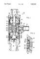
- FIG. 1is a cross-sectional and partially schematic view of a solenoid valve in accord with the preferred embodiment. Rear surfaces are not illustrated.
- FIG. 2is an enlarged view of the area circled in FIG. 1.
- the number 10designates a solenoid valve.
- fluidenters via a channel 11 formed through an inlet port 12, flows axially through a popper member 14 (hereinafter, "poppet") and through an annular orifice defined by a clearance 16 between the poppet and a valve seat 18, and exits the valve via a channel 19 formed through an outlet port 20.
- poppetpopper member 14
- the poppet 14serves to modulate flow to a degree which depends on the clearance 16.
- a magnetic subassembly 22is comprised of a permanent magnet 24 interposed between two wire coils 26, 28.
- the subassembly 22is captured in a ferromagnetic jacket 30 to form a structurally integral unit.
- the magnet 22 and coils 26,28can be arranged as shown and the portion of the flux path provided by the jacket 30 can be incorporated in the housing structure of the valve 10, or the entire arrangement can be such that a harmlessly small gap is provided between the housing structure and the magnet/coil combination.
- the essentially annular magnet 24is constructed in a conventional manner by providing a plurality of rectangular magnets sandwiched between wedge-shaped sections of an aluminum cage.
- the cagemaintains the magnets in proper positional relation so that the north and south poles are radially inward and outward, respectively, with reference to an axis 31 defined by the subassembly 22.
- the coils 26, 28are wound in a common direction for reasons described below.
- Leads (as at 32)extend from the coils 26, 28 to a connector 34 through which the coils are connected in series.
- the connector 34forms an electromechanical interface between the valve 10 and an external circuit which in use controls the position of the poppet 14 via pulse-width modulation.
- An interior ring nut 36is threadedly engaged with the main housing member 38 and defines the axial positions of a first pole piece 40 and a compound bellows structure 42.
- Another interior ring nut 44is threadedly engaged with the housing member 38 and defines the axial positions of a second pole piece 46 and another bellows structure 48.
- the latter bellows structure 48serves to radially center the poppet 14, and also to provide a desired spring rate as explained below.
- the bellowsare extended so that the structure 48 biases the poppet 14 away from the valve seat 18.
- the bellows structure 48comprises a radially outer member 50 which abuts the ring nut 44, and a radially inner member 52 which is threadedly engaged with the poppet 14.
- a retaining nut 54fixes the position of the radially inner member 52 relative to the poppet 14.
- An annular disc 56is captured between the radially outer member 50 and the outlet port 20, the latter being threadedly engaged with the main housing member 38. The disc 56 cooperates with the retaining nut 54 to limit downward movement of the poppet 14 in order to prevent damage to the valve seat 18.
- the valve seat 18is connected to the outlet port 20 by a bolt and washer combination 55 as illustrated.
- the compound bellows structure 42has a small-diameter bellows 57 and a large-diameter bellows 58.
- the smaller bellows 57has an effective diameter equal to that of the large-diameter portion 60 of the poppet 14. This serves the purpose of pressure balancing the poppet 14 so that the latter is substantially unresponsive to variations in fluid pressure.
- the larger bellows 58serves the same two purposes as the bellows structure 48, and is also extended (i.e. is in tension). Therefore, unlike the bellows structure 48, the bellows 58 biases the poppet 14 toward the valve seat 18.
- the compound bellows structure 42has a radially outer member 62 that abuts the ring nut 36, and a radially inner member 64 threadedly engaged with the poppet 14.
- a retaining nut 65 threadedly engaged with the poppet 14cooperates with an inner flange 66 formed on the inlet port 12 to limit movement of the poppet in the upward direction, as viewed in FIG. 1.
- the inlet port 12is threadedly engaged with the main housing member 38.
- a ferromagnetic armature 68is rigidly connected to the poppet 14 by a set screw 70.
- the annular armature 68has opposing ends 72, 74 and defines the same axis 31 as the subassembly 22.
- the ferromagnetic pole pieces 40, 46extend in a radially inward direction and then in an axial direction to form opposing annular faces 76, 78.
- a first gap 80is defined by the separation between the annular face 76 of the first pole piece 40 and the one annular end 72 of the armature 68.
- a second gap 82is defined by the separation between the annular face 78 of the second pole piece 46 and the other annular end 74 of the armature 68.
- the gaps 80, 82 and the clearance 16 between the poppet 14 and valve seat 18represent conditions attributable to the forces applied by the bellows structures 42, 48, and the positional interrelationship of the various structural elements of the valve 10 absent the magnet 24.
- the first gap 80 under these conditionsis larger than the second gap 82.
- the armature 68moves downward until the poppet 14 abuts the valve seat 18. Accordingly, the valve 10 is normally closed. In the closed condition, the second gap 82 is maintained as such (i.e. there is still a gap between the face 78 and end 74 of the pole piece 46 and the armature 68, respectively), but is smaller than illustrated in the drawings.
- the coils 26, 28are wound in a direction to ensure that when current flows through the coils, the electromagnetic flux (represented by arrow 84) attributable to the coils is, in the first gap 80, additive to the magnetic flux 86 attributable to the magnet 24. However, in the second gap 82, the flux 84 detracts from the flux 88 attributable to the magnet 24. The net effect is that the overall flux density becomes greater in the first gap 80 than in the second 82, and the armature 68 responds by moving to narrow the first gap while widening the second.
- the valve 10is thus opened to a degree which depends on the pulse width of the signals applied to the coils, and which is limited by the range of movement permitted by the retaining nut 64. When the opening movement of the poppet 14 is thus limited, the first gap 80 is maintained as such, but becomes smaller than the second gap 82.
- the inventioncan be practiced with the use of alternative structure which is functionally equivalent to that described above.
- the poppet 14 and valve seat 18could be replaced with a spool which variably opens a lateral channel.
- the bellows 48, 58could be replaced with a variety of conventional biasing mechanisms.
- Helical springscan be substituted but are not favored because of friction and potential buckling.
- Plate-type springscan be substituted (especially for bellows 58) but are not favored because, in order to provide a relatively uniform spring rate over the required stroke of the poppet 14, the diameter of the spring would be very large compared to the diameter of the bellows structure.
Landscapes
- Engineering & Computer Science (AREA)
- General Engineering & Computer Science (AREA)
- Physics & Mathematics (AREA)
- Mechanical Engineering (AREA)
- Electromagnetism (AREA)
- Power Engineering (AREA)
- Fluid Mechanics (AREA)
- Magnetically Actuated Valves (AREA)
Abstract
Description
The present invention relates generally to solenoid valves and more specifically to those which employ a permanent magnet and one or more coils in combination to control the position of an armature. Still more specifically, the invention relates to such valves that are designed to provide for flow modulation by selectively positioning the armature within its range of movement.
Attempts have been made to develop effective proportional solenoid valves suitable for use in flow modulation. In such applications, a key problem is nonlinearity of the relationship between applied force and displacement for the armature and attendant mass which is moved in order to provide flow modulation. This has led to designs such as those exemplified by U.S. Pat. No. 4,690,371 Bosley et al in which pressure sensing arrangements and feedback circuits are employed to compensate for thenonlinearity.
An approach different from the forementioned designs is disclosed in U.S. Pat. No. 4,988,074 Najmolhoda. In the '074 patent, an armature 22 is suspended by twoplate springs coil spring 42 is used to bias the armature in a direction which renders the valve normally closed. The force exerted by thecoil spring 42 must be sufficient to overcome both the magnetomotive force exerted on the armature by apermanent magnet 34 and the force exerted on the same by the pressurized fluid with which the valve operates. In many applications, this approach is unsatisfactory for reasons which will become evident from the following description.
An objective of the invention is to provide a proportional solenoid valve exhibiting highly linear response over the range of movement associated with its armature, spool, or other flow modulating element.
A further objective of the invention is to provide such a valve with relatively small radial dimensions.
A still further objective is to provide a solenoid valve that operates in a manner which is substantially independent on the pressure of the fluid which flows through the valve.
The invention is a permanent-magnet, proportional solenoid valve having a suspended armature which is separated from two opposing pole pieces by two normally unequal gaps having a collectively constant dimension, whereby the magnetic field originating from the magnet extends through the gaps and is used to bias the armature to a position at which the valve is normally closed, and wherein the electromagnetic field created by current flow through two commonly wound coils produces an additive effect on the flux density in one of the gaps while producing a subtractive effect on the flux density in the other gap, the armature moving away from the closed position in response to the additive and subtractive effects and to a degree which depends on the current flow through the coils.
For reasons explained below, the armature is preferably suspended by a combination of bellows structures which exert opposed biasing forces on the armature.
FIG. 1 is a cross-sectional and partially schematic view of a solenoid valve in accord with the preferred embodiment. Rear surfaces are not illustrated.
FIG. 2 is an enlarged view of the area circled in FIG. 1.
In FIG. 1, the number 10 designates a solenoid valve. In use of the valve 10, fluid enters via a channel 11 formed through aninlet port 12, flows axially through a popper member 14 (hereinafter, "poppet") and through an annular orifice defined by aclearance 16 between the poppet and avalve seat 18, and exits the valve via achannel 19 formed through anoutlet port 20. Accordingly, when the valve 10. is open, thepoppet 14 serves to modulate flow to a degree which depends on theclearance 16.
A magnetic subassembly 22 is comprised of apermanent magnet 24 interposed between twowire coils ferromagnetic jacket 30 to form a structurally integral unit. Alternatively, the magnet 22 andcoils jacket 30 can be incorporated in the housing structure of the valve 10, or the entire arrangement can be such that a harmlessly small gap is provided between the housing structure and the magnet/coil combination.
The essentiallyannular magnet 24 is constructed in a conventional manner by providing a plurality of rectangular magnets sandwiched between wedge-shaped sections of an aluminum cage. The cage maintains the magnets in proper positional relation so that the north and south poles are radially inward and outward, respectively, with reference to anaxis 31 defined by the subassembly 22.
Thecoils coils connector 34 through which the coils are connected in series. Theconnector 34 forms an electromechanical interface between the valve 10 and an external circuit which in use controls the position of thepoppet 14 via pulse-width modulation.
Aninterior ring nut 36 is threadedly engaged with themain housing member 38 and defines the axial positions of afirst pole piece 40 and acompound bellows structure 42. Anotherinterior ring nut 44 is threadedly engaged with thehousing member 38 and defines the axial positions of asecond pole piece 46 and anotherbellows structure 48. Thelatter bellows structure 48 serves to radially center thepoppet 14, and also to provide a desired spring rate as explained below. The bellows are extended so that thestructure 48 biases thepoppet 14 away from thevalve seat 18. Thebellows structure 48 comprises a radiallyouter member 50 which abuts thering nut 44, and a radiallyinner member 52 which is threadedly engaged with thepoppet 14. Aretaining nut 54 fixes the position of the radiallyinner member 52 relative to thepoppet 14. Anannular disc 56 is captured between the radiallyouter member 50 and theoutlet port 20, the latter being threadedly engaged with themain housing member 38. Thedisc 56 cooperates with theretaining nut 54 to limit downward movement of thepoppet 14 in order to prevent damage to thevalve seat 18. Thevalve seat 18 is connected to theoutlet port 20 by a bolt andwasher combination 55 as illustrated.
Thecompound bellows structure 42 has a small-diameter bellows 57 and a large-diameter bellows 58. Thesmaller bellows 57 has an effective diameter equal to that of the large-diameter portion 60 of thepoppet 14. This serves the purpose of pressure balancing thepoppet 14 so that the latter is substantially unresponsive to variations in fluid pressure. Thelarger bellows 58 serves the same two purposes as thebellows structure 48, and is also extended (i.e. is in tension). Therefore, unlike thebellows structure 48, thebellows 58 biases thepoppet 14 toward thevalve seat 18. Thecompound bellows structure 42 has a radiallyouter member 62 that abuts thering nut 36, and a radiallyinner member 64 threadedly engaged with thepoppet 14. Aretaining nut 65 threadedly engaged with thepoppet 14 cooperates with an inner flange 66 formed on theinlet port 12 to limit movement of the poppet in the upward direction, as viewed in FIG. 1. Theinlet port 12 is threadedly engaged with themain housing member 38.
Referring now to FIGS. 1 and 2, aferromagnetic armature 68 is rigidly connected to thepoppet 14 by a set screw 70. Theannular armature 68 hasopposing ends same axis 31 as the subassembly 22.
It will be observed that theferromagnetic pole pieces annular faces first gap 80 is defined by the separation between theannular face 76 of thefirst pole piece 40 and the oneannular end 72 of thearmature 68. A second gap 82 is defined by the separation between theannular face 78 of thesecond pole piece 46 and the otherannular end 74 of thearmature 68. Thesegaps 80, 82, and thus the position of thepoppet 14, are illustrated in FIG. 1 as they would be in the absence of the magnetomotive force originating from themagnet 24 and applied to thearmature 68. Thus, thegaps 80, 82 and theclearance 16 between thepoppet 14 andvalve seat 18 represent conditions attributable to the forces applied by thebellows structures magnet 24. As is evident from the drawings, thefirst gap 80 under these conditions is larger than the second gap 82. When the effect of themagnet 24 is added, the associated flux density is higher in the second gap 82 than in thefirst gap 80, and thearmature 68 moves downward until thepoppet 14 abuts thevalve seat 18. Accordingly, the valve 10 is normally closed. In the closed condition, the second gap 82 is maintained as such (i.e. there is still a gap between theface 78 and end 74 of thepole piece 46 and thearmature 68, respectively), but is smaller than illustrated in the drawings.
Thecoils first gap 80, additive to themagnetic flux 86 attributable to themagnet 24. However, in the second gap 82, theflux 84 detracts from theflux 88 attributable to themagnet 24. The net effect is that the overall flux density becomes greater in thefirst gap 80 than in the second 82, and thearmature 68 responds by moving to narrow the first gap while widening the second. The valve 10 is thus opened to a degree which depends on the pulse width of the signals applied to the coils, and which is limited by the range of movement permitted by the retainingnut 64. When the opening movement of thepoppet 14 is thus limited, thefirst gap 80 is maintained as such, but becomes smaller than the second gap 82.
The invention can be practiced with the use of alternative structure which is functionally equivalent to that described above. For example, thepoppet 14 andvalve seat 18 could be replaced with a spool which variably opens a lateral channel. Moreover, thebellows poppet 14, the diameter of the spring would be very large compared to the diameter of the bellows structure.
Accordingly, the illustrated embodiment of the invention is intended to serve a pedagogical purpose. The necessarily limited range of design options described above is not intended to limit the scope of the invention more than is just and proper in view of the teaching contained herein.
Claims (13)
1. A solenoid valve having an inlet and an outlet for a fluid which is to flow through the valve; the valve comprising in combination:
a first pole piece;
a second pole piece spaced from the first;
an armature defining a longitudinal axis thereof; the armature being interposed between and spaced from the pole pieces as determined by reference to the axis such that a first gap is formed between the armature and the first pole piece, and a second gap is formed between the armature and the second pole piece;
a valve seat relatively proximal to the second gap and relatively distal from the first gap;
modulating means rigidly connected to or integral with the armature for cooperating with the valve seat to alternatively prevent or permit fluid flow from the inlet to the outlet; the modulating means having first and second ends relatively proximal to the inlet and outlet, respectively;
a permanent magnet circumscribing the armature and being interposed between the pole pieces as determined by reference to the axis; the second gap being narrower than the first whereby flux density attributable to the magnet is greater in the second gap than in the first gap and the armature is operative, in response to magnetomotive force originating from the magnet, to urge the second end of the modulating means into abutment with the valve seat so that the valve is normally closed; the second gap being further narrowed and the first gap correspondingly widened when the armature is thus subjected to the magnetomotive force originating from the magnet; and
electromagnetic means for cooperating with the permanent magnet to move the modulating means in response to current flow; the electromagnetic means being operable to increase flux density in the first gap and simultaneously decrease flux density in the second gap sufficiently to move the modulating means away from the valve seat to a distance which renders the first gap narrower than the second gap while maintaining a clearance between the armature and the first pole piece.
2. A solenoid valve as recited in claim 1 wherein the electromagnetic means comprises first and second coils connected in series; the magnet being interposed between the coils as determined by reference to the axis.
3. A solenoid valve as recited in claim 1 wherein the electromagnetic means comprises first and second coils; the coils being wound in a common direction and the magnet being interposed between the coils as determined by reference to the axis.
4. A solenoid valve as recited in claim 3 further comprising first biasing means for impeding displacement of the modulating means toward the valve seat, the magnetomotive force being sufficiently large to overcome impedance attributable to the first biasing means so that the valve is normally closed.
5. A solenoid valve as recited in claim 4 further comprising second biasing means, independent on the magnetomotive force exerted by the permanent magnet, for impeding displacement of the modulating means away from valve seat.
6. A solenoid valve as recited in claim 4 wherein the first biasing means comprises a bellows structure connected to the modulating means.
7. A solenoid valve as recited in claim 5 wherein the second biasing means comprises a bellows structure connected to the modulating means.
8. A solenoid valve as recited in claim 6 wherein the second biasing means comprises a bellows structure connected to the modulating means.
9. A solenoid valve as recited in claim 1 further comprising first biasing means for impeding movement of the modulating means toward the valve seat; the magnetomotive force exerted by the permanent magnet being sufficiently large to overcome impedance attributable to the first biasing means.
10. A solenoid valve as recited in claim 9 further comprising second biasing means for impeding movement of the modulating means away from the valve seat.
11. A solenoid valve as recited in claim 9 wherein the first biasing means comprises a bellows structure connected to the modulating means.
12. A solenoid valve as recited in claim 10 wherein the second biasing means comprises a bellows structure connected to the modulating means.
13. A solenoid valve as recited in claim 12 wherein the first biasing means comprises a bellows structure connected to the modulating means.
Priority Applications (1)
| Application Number | Priority Date | Filing Date | Title |
|---|---|---|---|
| US07/991,020US5351934A (en) | 1992-12-15 | 1992-12-15 | Proportional solenoid valve |
Applications Claiming Priority (1)
| Application Number | Priority Date | Filing Date | Title |
|---|---|---|---|
| US07/991,020US5351934A (en) | 1992-12-15 | 1992-12-15 | Proportional solenoid valve |
Publications (1)
| Publication Number | Publication Date |
|---|---|
| US5351934Atrue US5351934A (en) | 1994-10-04 |
Family
ID=25536765
Family Applications (1)
| Application Number | Title | Priority Date | Filing Date |
|---|---|---|---|
| US07/991,020Expired - LifetimeUS5351934A (en) | 1992-12-15 | 1992-12-15 | Proportional solenoid valve |
Country Status (1)
| Country | Link |
|---|---|
| US (1) | US5351934A (en) |
Cited By (50)
| Publication number | Priority date | Publication date | Assignee | Title |
|---|---|---|---|---|
| US5529281A (en)* | 1994-08-24 | 1996-06-25 | The United States Of America As Represented By The Administrator Of National Aeronautics And Space | Dual-latching solenoid-actuated valve assembly |
| US5531421A (en)* | 1993-09-23 | 1996-07-02 | Hoechst Aktiengesellschaft | Annular dam slide valve |
| US5863024A (en)* | 1994-12-30 | 1999-01-26 | Crouzet Automatismes | Micro-Electromagnet including an integrated magnetic circuit and coil |
| WO2000004754A2 (en) | 1998-07-21 | 2000-02-03 | Micro-Heat, Inc. | Solenoid valve with permanent magnet |
| US6501358B2 (en)* | 1998-06-26 | 2002-12-31 | Siemens Automotive Corporation | Electromagnetic actuator with molded connector |
| US20030141772A1 (en)* | 2002-01-30 | 2003-07-31 | Abel Stephen G. | System and method for controlling an active magnetic bearing using continuous variable compensation |
| US6603230B1 (en) | 2002-01-30 | 2003-08-05 | Honeywell International, Inc. | Active magnetic bearing assembly using permanent magnet biased homopolar and reluctance centering effects |
| US20030217772A1 (en)* | 2002-05-23 | 2003-11-27 | Lu Jyh-Woei J. | Optical sensor method, system and apparatus |
| US6669109B2 (en) | 1998-11-06 | 2003-12-30 | Micro-Heat Inc | Apparatus for cleaning or de-icing a vehicle window |
| US20040108482A1 (en)* | 2002-10-25 | 2004-06-10 | Takeshi Sakuragi | Electromagnetically driven valve device |
| US6782196B1 (en) | 2003-02-28 | 2004-08-24 | Valeo Electrical Systems, Inc. | Fluid heater with freeze protection |
| US6783114B2 (en) | 2001-12-11 | 2004-08-31 | Honeywell International, Inc. | Cable assembly and air outflow valve incorporating the same |
| US20040170414A1 (en)* | 2003-02-28 | 2004-09-02 | Karl-Heinz Kuebler | Fluid heater control apparatus and method with overtemperature protection |
| US20040170411A1 (en)* | 2003-02-28 | 2004-09-02 | Karl-Heinz Kuebler | Fluid heater temperature control apparatus and method |
| US6789744B2 (en) | 2002-01-29 | 2004-09-14 | Valeo Electrical Systems, Inc. | Fluid heater with a variable mass flow path |
| US20040197094A1 (en)* | 2003-04-04 | 2004-10-07 | Amberg Michael T. | Fluid heater with compressible cover freeze protection |
| US20040216792A1 (en)* | 2003-04-30 | 2004-11-04 | Bunn Andrew D. | Fully integrated aircraft cabin pressure control system valve |
| US20040217317A1 (en)* | 2003-04-30 | 2004-11-04 | Bunn Andrew D. | Cabin pressure outflow control valve having non-linear flow control characteristics |
| US20040216782A1 (en)* | 2003-05-03 | 2004-11-04 | Mares E. Joseph | Gas turbine metering valve |
| US20040264951A1 (en)* | 2003-06-27 | 2004-12-30 | Karl-Heinz Kuebler | Fluid heater with low porosity thermal mass |
| US20050019028A1 (en)* | 2003-07-25 | 2005-01-27 | Karl-Heinz Kuebler | Fluid heater with integral heater elements |
| US20050047768A1 (en)* | 2003-08-29 | 2005-03-03 | Valeo Electrical Systems, Inc. | Fluid heater with integral heater element ground connections |
| US20050086758A1 (en)* | 2001-05-14 | 2005-04-28 | Uri Arkashevski | System and method for cleaning or de-icing a windshield |
| US6892745B2 (en) | 2002-04-10 | 2005-05-17 | Honeywell International Inc. | Flow control valve with integral sensor and controller and related method |
| US6895991B2 (en) | 2002-08-09 | 2005-05-24 | Honeywell International, Inc. | Missile thrust system and valve with refractory piston cylinder |
| US6912357B2 (en) | 2002-01-29 | 2005-06-28 | Valeo Electrical Systems, Inc. | Fluid heater |
| US6952524B2 (en) | 2002-11-27 | 2005-10-04 | Valeo Electrical Systems, Inc. | Fluid heater temperature balancing apparatus |
| US6951317B2 (en) | 2002-09-03 | 2005-10-04 | Honeywell International Inc. | Vehicle, lightweight pneumatic pilot valve and related systems therefor |
| US20060102744A1 (en)* | 2002-10-21 | 2006-05-18 | Uri Arkasjevski | Apparatus and method for cleaning or de-icing vehicle elements |
| EP1676069A1 (en)* | 2003-10-22 | 2006-07-05 | Elopak Systems Ag | Electromagnetic valve device for and a method of controlling fluid flow |
| US20100010479A1 (en)* | 2002-09-20 | 2010-01-14 | Erickson John H | Dosage control apparatus |
| US20100123092A1 (en)* | 2008-11-17 | 2010-05-20 | Ckd Corporation | Fluid control valve |
| US20110006081A1 (en)* | 2004-02-12 | 2011-01-13 | Uri Arkashevski | Apparatus and method for cleaning and de-icing |
| US8391695B2 (en) | 2006-07-24 | 2013-03-05 | M-Heat Investors, Llc | Vehicle surfaces cleaning and de-icing system and method |
| US20130193778A1 (en)* | 2010-07-05 | 2013-08-01 | Olympus Winter & Ibe Gmbh | Electromagnetic actuator for a surgical instrument |
| US20130333905A1 (en)* | 2012-06-15 | 2013-12-19 | Hilti Aktiengesellschaft | Machine Tool and Control Method |
| US20150069279A1 (en)* | 2012-04-16 | 2015-03-12 | Danfoss A/S | Axial valve |
| US20150330311A1 (en)* | 2014-05-15 | 2015-11-19 | Hamilton Sundstrand Corporation | Fuel metering valve and method of managing fuel in a metering valve |
| US20160148769A1 (en)* | 2013-06-20 | 2016-05-26 | Rhefor Gbr (Vertreten Durch Den Geschäftsführend- En Gesellschafter Arno Mecklenburg) | Self-holding magnet with a particularly low electric trigger voltage |
| US20170067572A1 (en)* | 2014-03-19 | 2017-03-09 | Bitron S.P.A. | Bistable electric valve, in particular for a system for recovering petrol vapours in a motor vehicle |
| US20170089484A1 (en)* | 2015-09-28 | 2017-03-30 | Friedrich Müller | Coaxially designed, pressure-compensated, directly controlled valve with low pressure losses |
| US20170175919A1 (en)* | 2015-12-17 | 2017-06-22 | Glen A. Robertson | Power versatile and energy efficient electric coaxial valve |
| US20170317570A1 (en)* | 2014-10-29 | 2017-11-02 | Kyb Corporation | Linear actuator |
| US20170370339A1 (en)* | 2016-06-24 | 2017-12-28 | Borgwarner Inc. | Solenoid having selective latch for solenoid-actuated valve |
| WO2018046909A1 (en)* | 2016-09-09 | 2018-03-15 | Camcon Medical Limited | Electromagnetic actuator |
| EP3608569A1 (en)* | 2018-08-05 | 2020-02-12 | Electronics, Inc. | Flow control valve with eddy current dampening |
| CN111108317A (en)* | 2017-09-23 | 2020-05-05 | 贺德克配件有限公司 | Valve device |
| US11361894B2 (en)* | 2018-03-13 | 2022-06-14 | Husco Automotive Holdings Llc | Bi-stable solenoid with an intermediate condition |
| US20230197324A1 (en)* | 2021-11-09 | 2023-06-22 | Systems, Machines, Automation Components Corporation | Low-cost linear actuator having a moving printed coil assembly defined on a printed circuit board |
| US11837936B2 (en)* | 2012-05-22 | 2023-12-05 | Minebea Mitsumi, Inc. | Vibrator generator having swing unit, frame and elastic member |
Citations (21)
| Publication number | Priority date | Publication date | Assignee | Title |
|---|---|---|---|---|
| US2279243A (en)* | 1940-07-23 | 1942-04-07 | John B Parsons | Solenoid actuated valve |
| US2579723A (en)* | 1947-10-28 | 1951-12-25 | United Aircraft Corp | Magnetic device |
| US3007672A (en)* | 1960-12-21 | 1961-11-07 | Union Tank Car Co | Electromagnetically operated valve |
| US3125321A (en)* | 1964-03-17 | Solenoid activated flow valve | ||
| US3321177A (en)* | 1964-08-06 | 1967-05-23 | Specialties Dev Corp | Valve for fluid medium under pressure |
| US3502105A (en)* | 1966-07-27 | 1970-03-24 | Lignes Telegraph Telephon | Electromagnetic valves and application thereof to digital valves |
| US4004258A (en)* | 1974-11-20 | 1977-01-18 | Valcor Engineering Corporation | Position indicating pulse latching solenoid |
| US4299252A (en)* | 1979-07-05 | 1981-11-10 | Consolidated Controls Corporation | Permanent magnet boosted electromagnetic actuator |
| US4538129A (en)* | 1981-05-18 | 1985-08-27 | Fisher Richard T | Magnetic flux-shifting actuator |
| US4541429A (en)* | 1982-05-10 | 1985-09-17 | Prosl Frank R | Implantable magnetically-actuated valve |
| US4564046A (en)* | 1982-02-25 | 1986-01-14 | Robert Bosch Gmbh | Solenoid valve |
| SU1221443A1 (en)* | 1984-06-29 | 1986-03-30 | Отделение Всесоюзного научно-исследовательского института электромеханики | Solenoid valve |
| US4598736A (en)* | 1984-12-03 | 1986-07-08 | Chorkey William J | Solenoid operated valve with balancing means |
| US4614327A (en)* | 1984-11-12 | 1986-09-30 | Danfoss A/S | Valve for volatile liquids, particularly expansion valve for refrigeration plants |
| US4621788A (en)* | 1985-08-07 | 1986-11-11 | Controls Company Of America | Solenoid valve |
| US4690371A (en)* | 1985-10-22 | 1987-09-01 | Innovus | Electromagnetic valve with permanent magnet armature |
| US4829947A (en)* | 1987-08-12 | 1989-05-16 | General Motors Corporation | Variable lift operation of bistable electromechanical poppet valve actuator |
| US4890815A (en)* | 1982-10-09 | 1990-01-02 | Robert Bosch Gmbh | Valve with membrane spring |
| US4988074A (en)* | 1988-05-17 | 1991-01-29 | Hi-Ram, Inc. | Proportional variable force solenoid control valve |
| US5083747A (en)* | 1991-01-28 | 1992-01-28 | Siemens Automotive L.P. | Hat shaped armature for solenoid valve |
| US5108070A (en)* | 1990-03-28 | 1992-04-28 | Mitsubishi Denki Kabushiki Kaisha | Flow control solenoid valve apparatus |
- 1992
- 1992-12-15USUS07/991,020patent/US5351934A/ennot_activeExpired - Lifetime
Patent Citations (21)
| Publication number | Priority date | Publication date | Assignee | Title |
|---|---|---|---|---|
| US3125321A (en)* | 1964-03-17 | Solenoid activated flow valve | ||
| US2279243A (en)* | 1940-07-23 | 1942-04-07 | John B Parsons | Solenoid actuated valve |
| US2579723A (en)* | 1947-10-28 | 1951-12-25 | United Aircraft Corp | Magnetic device |
| US3007672A (en)* | 1960-12-21 | 1961-11-07 | Union Tank Car Co | Electromagnetically operated valve |
| US3321177A (en)* | 1964-08-06 | 1967-05-23 | Specialties Dev Corp | Valve for fluid medium under pressure |
| US3502105A (en)* | 1966-07-27 | 1970-03-24 | Lignes Telegraph Telephon | Electromagnetic valves and application thereof to digital valves |
| US4004258A (en)* | 1974-11-20 | 1977-01-18 | Valcor Engineering Corporation | Position indicating pulse latching solenoid |
| US4299252A (en)* | 1979-07-05 | 1981-11-10 | Consolidated Controls Corporation | Permanent magnet boosted electromagnetic actuator |
| US4538129A (en)* | 1981-05-18 | 1985-08-27 | Fisher Richard T | Magnetic flux-shifting actuator |
| US4564046A (en)* | 1982-02-25 | 1986-01-14 | Robert Bosch Gmbh | Solenoid valve |
| US4541429A (en)* | 1982-05-10 | 1985-09-17 | Prosl Frank R | Implantable magnetically-actuated valve |
| US4890815A (en)* | 1982-10-09 | 1990-01-02 | Robert Bosch Gmbh | Valve with membrane spring |
| SU1221443A1 (en)* | 1984-06-29 | 1986-03-30 | Отделение Всесоюзного научно-исследовательского института электромеханики | Solenoid valve |
| US4614327A (en)* | 1984-11-12 | 1986-09-30 | Danfoss A/S | Valve for volatile liquids, particularly expansion valve for refrigeration plants |
| US4598736A (en)* | 1984-12-03 | 1986-07-08 | Chorkey William J | Solenoid operated valve with balancing means |
| US4621788A (en)* | 1985-08-07 | 1986-11-11 | Controls Company Of America | Solenoid valve |
| US4690371A (en)* | 1985-10-22 | 1987-09-01 | Innovus | Electromagnetic valve with permanent magnet armature |
| US4829947A (en)* | 1987-08-12 | 1989-05-16 | General Motors Corporation | Variable lift operation of bistable electromechanical poppet valve actuator |
| US4988074A (en)* | 1988-05-17 | 1991-01-29 | Hi-Ram, Inc. | Proportional variable force solenoid control valve |
| US5108070A (en)* | 1990-03-28 | 1992-04-28 | Mitsubishi Denki Kabushiki Kaisha | Flow control solenoid valve apparatus |
| US5083747A (en)* | 1991-01-28 | 1992-01-28 | Siemens Automotive L.P. | Hat shaped armature for solenoid valve |
Cited By (83)
| Publication number | Priority date | Publication date | Assignee | Title |
|---|---|---|---|---|
| US5531421A (en)* | 1993-09-23 | 1996-07-02 | Hoechst Aktiengesellschaft | Annular dam slide valve |
| US5529281A (en)* | 1994-08-24 | 1996-06-25 | The United States Of America As Represented By The Administrator Of National Aeronautics And Space | Dual-latching solenoid-actuated valve assembly |
| US5863024A (en)* | 1994-12-30 | 1999-01-26 | Crouzet Automatismes | Micro-Electromagnet including an integrated magnetic circuit and coil |
| US6501358B2 (en)* | 1998-06-26 | 2002-12-31 | Siemens Automotive Corporation | Electromagnetic actuator with molded connector |
| WO2000004754A2 (en) | 1998-07-21 | 2000-02-03 | Micro-Heat, Inc. | Solenoid valve with permanent magnet |
| US6199587B1 (en) | 1998-07-21 | 2001-03-13 | Franco Shlomi | Solenoid valve with permanent magnet |
| US6669109B2 (en) | 1998-11-06 | 2003-12-30 | Micro-Heat Inc | Apparatus for cleaning or de-icing a vehicle window |
| US20040112981A1 (en)* | 1998-11-06 | 2004-06-17 | Vyshislav Ivanov | Apparatus for cleaning or de-icing a vehicle window |
| US20050086758A1 (en)* | 2001-05-14 | 2005-04-28 | Uri Arkashevski | System and method for cleaning or de-icing a windshield |
| US6783114B2 (en) | 2001-12-11 | 2004-08-31 | Honeywell International, Inc. | Cable assembly and air outflow valve incorporating the same |
| US6912357B2 (en) | 2002-01-29 | 2005-06-28 | Valeo Electrical Systems, Inc. | Fluid heater |
| US6789744B2 (en) | 2002-01-29 | 2004-09-14 | Valeo Electrical Systems, Inc. | Fluid heater with a variable mass flow path |
| US6603230B1 (en) | 2002-01-30 | 2003-08-05 | Honeywell International, Inc. | Active magnetic bearing assembly using permanent magnet biased homopolar and reluctance centering effects |
| US6734650B2 (en) | 2002-01-30 | 2004-05-11 | Honeywell International, Inc. | System and method for controlling an active magnetic bearing using continuous variable compensation |
| US20030141772A1 (en)* | 2002-01-30 | 2003-07-31 | Abel Stephen G. | System and method for controlling an active magnetic bearing using continuous variable compensation |
| US6892745B2 (en) | 2002-04-10 | 2005-05-17 | Honeywell International Inc. | Flow control valve with integral sensor and controller and related method |
| US7038192B2 (en) | 2002-05-23 | 2006-05-02 | Honeywell International, Inc. | Optical sensor method, system and apparatus |
| US20030217772A1 (en)* | 2002-05-23 | 2003-11-27 | Lu Jyh-Woei J. | Optical sensor method, system and apparatus |
| US6895991B2 (en) | 2002-08-09 | 2005-05-24 | Honeywell International, Inc. | Missile thrust system and valve with refractory piston cylinder |
| US6951317B2 (en) | 2002-09-03 | 2005-10-04 | Honeywell International Inc. | Vehicle, lightweight pneumatic pilot valve and related systems therefor |
| US7896018B2 (en)* | 2002-09-20 | 2011-03-01 | Advanced Neuromodulation Systems, Inc. | Dosage control apparatus |
| US20100010479A1 (en)* | 2002-09-20 | 2010-01-14 | Erickson John H | Dosage control apparatus |
| US20060102744A1 (en)* | 2002-10-21 | 2006-05-18 | Uri Arkasjevski | Apparatus and method for cleaning or de-icing vehicle elements |
| US8561917B2 (en) | 2002-10-21 | 2013-10-22 | M-Heat Investors, Llc | Apparatus and method for cleaning or de-icing vehicle elements |
| US7156366B2 (en)* | 2002-10-25 | 2007-01-02 | Toyota Jidosha Kabushiki Kaisha | Electromagnetically driven valve device |
| US20040108482A1 (en)* | 2002-10-25 | 2004-06-10 | Takeshi Sakuragi | Electromagnetically driven valve device |
| US6952524B2 (en) | 2002-11-27 | 2005-10-04 | Valeo Electrical Systems, Inc. | Fluid heater temperature balancing apparatus |
| US6782196B1 (en) | 2003-02-28 | 2004-08-24 | Valeo Electrical Systems, Inc. | Fluid heater with freeze protection |
| US20040170412A1 (en)* | 2003-02-28 | 2004-09-02 | Karl-Heinz Kuebler | Fluid heater with freeze protection |
| US6850699B2 (en) | 2003-02-28 | 2005-02-01 | Valeo Electrical Systems, Inc. | Fluid heater temperature control apparatus and method |
| US6839509B2 (en) | 2003-02-28 | 2005-01-04 | Valeo Electrical Systems, Inc. | Fluid heater control apparatus and method with overtemperature protection |
| US20040170411A1 (en)* | 2003-02-28 | 2004-09-02 | Karl-Heinz Kuebler | Fluid heater temperature control apparatus and method |
| US20040170414A1 (en)* | 2003-02-28 | 2004-09-02 | Karl-Heinz Kuebler | Fluid heater control apparatus and method with overtemperature protection |
| US6889005B2 (en) | 2003-04-04 | 2005-05-03 | Valeo Electrical Systems, Inc. | Fluid heater with compressible cover freeze protection |
| US20040197094A1 (en)* | 2003-04-04 | 2004-10-07 | Amberg Michael T. | Fluid heater with compressible cover freeze protection |
| US20040216792A1 (en)* | 2003-04-30 | 2004-11-04 | Bunn Andrew D. | Fully integrated aircraft cabin pressure control system valve |
| US6962324B2 (en) | 2003-04-30 | 2005-11-08 | Honeywell International, Inc. | Cabin pressure outflow control valve having non-linear flow control characteristics |
| US20040217317A1 (en)* | 2003-04-30 | 2004-11-04 | Bunn Andrew D. | Cabin pressure outflow control valve having non-linear flow control characteristics |
| US6945278B2 (en) | 2003-04-30 | 2005-09-20 | Honeywell International, Inc. | Fully integrated aircraft cabin pressure control system valve |
| US20040216782A1 (en)* | 2003-05-03 | 2004-11-04 | Mares E. Joseph | Gas turbine metering valve |
| US8763631B2 (en) | 2003-05-03 | 2014-07-01 | Precision Engine Controls Corporation | Gas turbine metering valve |
| US7190893B2 (en) | 2003-06-27 | 2007-03-13 | Valeo Electrical Systems, Inc. | Fluid heater with low porosity thermal mass |
| US20040264951A1 (en)* | 2003-06-27 | 2004-12-30 | Karl-Heinz Kuebler | Fluid heater with low porosity thermal mass |
| US20050019028A1 (en)* | 2003-07-25 | 2005-01-27 | Karl-Heinz Kuebler | Fluid heater with integral heater elements |
| US20050047768A1 (en)* | 2003-08-29 | 2005-03-03 | Valeo Electrical Systems, Inc. | Fluid heater with integral heater element ground connections |
| EP1676069A1 (en)* | 2003-10-22 | 2006-07-05 | Elopak Systems Ag | Electromagnetic valve device for and a method of controlling fluid flow |
| US20070261736A1 (en)* | 2003-10-22 | 2007-11-15 | Elopak Systems Ag | Valve Device for and a Method of Controlling Fluid Flow |
| US20110006081A1 (en)* | 2004-02-12 | 2011-01-13 | Uri Arkashevski | Apparatus and method for cleaning and de-icing |
| US7905427B2 (en) | 2004-02-12 | 2011-03-15 | M-Heat Investors, Llc | Apparatus and method for cleaning and de-icing |
| US8366022B2 (en) | 2004-02-12 | 2013-02-05 | M-Heat Investors, Llc | Apparatus and method for cleaning and de-icing |
| US8391695B2 (en) | 2006-07-24 | 2013-03-05 | M-Heat Investors, Llc | Vehicle surfaces cleaning and de-icing system and method |
| US20100123092A1 (en)* | 2008-11-17 | 2010-05-20 | Ckd Corporation | Fluid control valve |
| US9385580B2 (en)* | 2010-07-05 | 2016-07-05 | Olympus Winter & Ibe Gmbh | Electromagnetic actuator for a surgical instrument |
| US20130193778A1 (en)* | 2010-07-05 | 2013-08-01 | Olympus Winter & Ibe Gmbh | Electromagnetic actuator for a surgical instrument |
| US20150069279A1 (en)* | 2012-04-16 | 2015-03-12 | Danfoss A/S | Axial valve |
| US9334967B2 (en)* | 2012-04-16 | 2016-05-10 | Danfoss A/S | Axial valve |
| US11837936B2 (en)* | 2012-05-22 | 2023-12-05 | Minebea Mitsumi, Inc. | Vibrator generator having swing unit, frame and elastic member |
| US12095330B2 (en)* | 2012-05-22 | 2024-09-17 | Minebea Mitsumi Inc. | Vibrator generator having swing unit, frame and elastic member |
| US20240055964A1 (en)* | 2012-05-22 | 2024-02-15 | Minebea Mitsumi Inc. | Vibrator generator having swing unit, frame and elastic member |
| US20130333905A1 (en)* | 2012-06-15 | 2013-12-19 | Hilti Aktiengesellschaft | Machine Tool and Control Method |
| US20160148769A1 (en)* | 2013-06-20 | 2016-05-26 | Rhefor Gbr (Vertreten Durch Den Geschäftsführend- En Gesellschafter Arno Mecklenburg) | Self-holding magnet with a particularly low electric trigger voltage |
| US9953786B2 (en)* | 2013-06-20 | 2018-04-24 | Rhefor Gbr (Vertreten Durch Den Geschaeftsfuehrenden Gesellschafter Arno Mecklenburg) | Self-holding magnet with a particularly low electric trigger voltage |
| US9970566B2 (en)* | 2014-03-19 | 2018-05-15 | Bitron S.P.A. | Bistable electric valve, in particular for a system for recovering petrol vapours in a motor vehicle |
| US20170067572A1 (en)* | 2014-03-19 | 2017-03-09 | Bitron S.P.A. | Bistable electric valve, in particular for a system for recovering petrol vapours in a motor vehicle |
| US9739203B2 (en)* | 2014-05-15 | 2017-08-22 | Hamilton Sundstrand Corporation | Fuel metering valve and method of managing fuel in a metering valve |
| US20150330311A1 (en)* | 2014-05-15 | 2015-11-19 | Hamilton Sundstrand Corporation | Fuel metering valve and method of managing fuel in a metering valve |
| US20170317570A1 (en)* | 2014-10-29 | 2017-11-02 | Kyb Corporation | Linear actuator |
| US20170089484A1 (en)* | 2015-09-28 | 2017-03-30 | Friedrich Müller | Coaxially designed, pressure-compensated, directly controlled valve with low pressure losses |
| US10041598B2 (en)* | 2015-09-28 | 2018-08-07 | Friedrich Müller | Coaxially designed, pressure-compensated, directly controlled valve with low pressure losses |
| US9702477B1 (en)* | 2015-12-17 | 2017-07-11 | Glen A. Robertson | Power versatile and energy efficient electric coaxial valve |
| US20170175919A1 (en)* | 2015-12-17 | 2017-06-22 | Glen A. Robertson | Power versatile and energy efficient electric coaxial valve |
| US20170370339A1 (en)* | 2016-06-24 | 2017-12-28 | Borgwarner Inc. | Solenoid having selective latch for solenoid-actuated valve |
| US10167832B2 (en)* | 2016-06-24 | 2019-01-01 | Borgwarner Inc. | Solenoid having selective latch for solenoid-actuated valve |
| WO2018046909A1 (en)* | 2016-09-09 | 2018-03-15 | Camcon Medical Limited | Electromagnetic actuator |
| CN111108317A (en)* | 2017-09-23 | 2020-05-05 | 贺德克配件有限公司 | Valve device |
| US11901120B2 (en)* | 2018-03-13 | 2024-02-13 | Husco Automotive Holdings Llc | Bi-stable solenoid with an intermediate condition |
| US20220375672A1 (en)* | 2018-03-13 | 2022-11-24 | Husco Automotive Holdings Llc | Bi-Stable Solenoid With an Intermediate Condition |
| US11361894B2 (en)* | 2018-03-13 | 2022-06-14 | Husco Automotive Holdings Llc | Bi-stable solenoid with an intermediate condition |
| CN110805702A (en)* | 2018-08-05 | 2020-02-18 | 电子股份有限公司 | Flow control valve with vortex flow damping |
| WO2020032987A1 (en)* | 2018-08-05 | 2020-02-13 | Electronics Inc. | Flow control valve with eddy current dampening |
| EP3608569A1 (en)* | 2018-08-05 | 2020-02-12 | Electronics, Inc. | Flow control valve with eddy current dampening |
| US20230197324A1 (en)* | 2021-11-09 | 2023-06-22 | Systems, Machines, Automation Components Corporation | Low-cost linear actuator having a moving printed coil assembly defined on a printed circuit board |
| US12087505B2 (en)* | 2021-11-09 | 2024-09-10 | Systems, Machines, Automation Components Corporation | Low-cost linear actuator having a moving printed coil assembly defined on a printed circuit board |
Similar Documents
| Publication | Publication Date | Title |
|---|---|---|
| US5351934A (en) | Proportional solenoid valve | |
| AU627683B2 (en) | Solenoid actuator having a magnetic flux sensor | |
| US4463332A (en) | Adjustable, rectilinear motion proportional solenoid | |
| US6179268B1 (en) | Proportional variable force solenoid control valve with segmented permanent magnet | |
| EP0451347B1 (en) | Bypass flow pressure regulator | |
| US4641072A (en) | Electro-mechanical actuator | |
| US6422533B1 (en) | High force solenoid valve and method of improved solenoid valve performance | |
| CN102720878B (en) | Solenoid operated fluid control valve | |
| US4966195A (en) | Transmission pressure regulator | |
| US4848721A (en) | Hydraulic valve with integrated solenoid | |
| US4452424A (en) | Electromagnetic linear control valve | |
| KR950002534B1 (en) | Solenoid valve | |
| JPH0755039B2 (en) | Force motor | |
| US5860631A (en) | Pilot valve for suspension control systems | |
| US4322057A (en) | Electromagnetically operated valve unit | |
| US20020000530A1 (en) | Proportional solenoid-controlled fluid valve assembly without non-magnetic alignment support element | |
| CN86106267A (en) | High Sensitivity Magnetic Adjuster | |
| EP0564794A1 (en) | Double acting electromagnetic actuator | |
| US4658231A (en) | Actuating magnet with enlarged plunger pole piece | |
| US6167906B1 (en) | Bi-directional flow control valve | |
| GB1559919A (en) | Pressure regulating valve | |
| US4530374A (en) | Linear motor-actuated flow control valve | |
| JP3795247B2 (en) | Electromagnetic servo valve driving method and electromagnetic servo valve | |
| US4778147A (en) | Electromagnetic solenoid | |
| US4677409A (en) | Electromagnetic solenoid with a replaceable fixed iron core |
Legal Events
| Date | Code | Title | Description |
|---|---|---|---|
| AS | Assignment | Owner name:ALLIED-SIGNAL INC., NEW JERSEY Free format text:ASSIGNMENT OF ASSIGNORS INTEREST.;ASSIGNORS:JENSEN, RON B.;GUYUAX, JAMES R.;REEL/FRAME:006340/0338 Effective date:19921214 | |
| AS | Assignment | Owner name:ALLIEDSIGNAL INC., NEW JERSEY Free format text:CHANGE OF NAME;ASSIGNOR:ALLIED-SIGNAL INC.;REEL/FRAME:006704/0091 Effective date:19930426 | |
| STCF | Information on status: patent grant | Free format text:PATENTED CASE | |
| FEPP | Fee payment procedure | Free format text:PAYOR NUMBER ASSIGNED (ORIGINAL EVENT CODE: ASPN); ENTITY STATUS OF PATENT OWNER: LARGE ENTITY | |
| FPAY | Fee payment | Year of fee payment:4 | |
| FPAY | Fee payment | Year of fee payment:8 | |
| REMI | Maintenance fee reminder mailed | ||
| FPAY | Fee payment | Year of fee payment:12 |