US5351897A - Adjustable ergonomic support for computer keyboards - Google Patents
Adjustable ergonomic support for computer keyboardsDownload PDFInfo
- Publication number
- US5351897A US5351897AUS07/871,108US87110892AUS5351897AUS 5351897 AUS5351897 AUS 5351897AUS 87110892 AUS87110892 AUS 87110892AUS 5351897 AUS5351897 AUS 5351897A
- Authority
- US
- United States
- Prior art keywords
- keyboard
- movable member
- operator
- platform
- support
- Prior art date
- Legal status (The legal status is an assumption and is not a legal conclusion. Google has not performed a legal analysis and makes no representation as to the accuracy of the status listed.)
- Expired - Fee Related
Links
- 230000006835compressionEffects0.000claimsdescription7
- 238000007906compressionMethods0.000claimsdescription7
- 230000002093peripheral effectEffects0.000claimsdescription5
- 239000004020conductorSubstances0.000claimsdescription3
- OKTJSMMVPCPJKN-UHFFFAOYSA-NCarbonChemical compound[C]OKTJSMMVPCPJKN-UHFFFAOYSA-N0.000claimsdescription2
- 229910052799carbonInorganic materials0.000claimsdescription2
- 230000003319supportive effectEffects0.000claims1
- 210000000707wristAnatomy0.000abstractdescription25
- 230000007935neutral effectEffects0.000abstractdescription11
- 208000003295carpal tunnel syndromeDiseases0.000abstractdescription8
- 210000000245forearmAnatomy0.000abstractdescription7
- 230000003247decreasing effectEffects0.000abstract1
- 210000003811fingerAnatomy0.000description8
- 238000013479data entryMethods0.000description5
- 238000011161developmentMethods0.000description4
- 230000018109developmental processEffects0.000description4
- 238000000034methodMethods0.000description4
- 238000012545processingMethods0.000description4
- 230000008901benefitEffects0.000description3
- 238000012937correctionMethods0.000description3
- 208000014674injuryDiseases0.000description3
- 238000013461designMethods0.000description2
- 229920001971elastomerPolymers0.000description2
- 239000004816latexSubstances0.000description2
- 229920000126latexPolymers0.000description2
- 230000003014reinforcing effectEffects0.000description2
- 239000000126substanceSubstances0.000description2
- 210000003813thumbAnatomy0.000description2
- 230000008733traumaEffects0.000description2
- 208000027418Wounds and injuryDiseases0.000description1
- 230000006978adaptationEffects0.000description1
- 210000003484anatomyAnatomy0.000description1
- 210000000617armAnatomy0.000description1
- 210000000988bone and boneAnatomy0.000description1
- 230000008859changeEffects0.000description1
- 238000004891communicationMethods0.000description1
- 230000000052comparative effectEffects0.000description1
- 230000006378damageEffects0.000description1
- 230000000694effectsEffects0.000description1
- 230000008030eliminationEffects0.000description1
- 238000003379elimination reactionMethods0.000description1
- 238000005516engineering processMethods0.000description1
- 210000004247handAnatomy0.000description1
- 238000005470impregnationMethods0.000description1
- 210000003041ligamentAnatomy0.000description1
- 238000012423maintenanceMethods0.000description1
- 239000000463materialSubstances0.000description1
- 230000007246mechanismEffects0.000description1
- 238000012986modificationMethods0.000description1
- 230000004048modificationEffects0.000description1
- 210000005036nerveAnatomy0.000description1
- 210000000944nerve tissueAnatomy0.000description1
- 231100000862numbnessToxicity0.000description1
- 239000004033plasticSubstances0.000description1
- 230000008569processEffects0.000description1
- 238000011084recoveryMethods0.000description1
- 230000009467reductionEffects0.000description1
- 238000001356surgical procedureMethods0.000description1
- 210000001519tissueAnatomy0.000description1
- 238000012546transferMethods0.000description1
- 230000000007visual effectEffects0.000description1
Images


Classifications
- A—HUMAN NECESSITIES
- A47—FURNITURE; DOMESTIC ARTICLES OR APPLIANCES; COFFEE MILLS; SPICE MILLS; SUCTION CLEANERS IN GENERAL
- A47B—TABLES; DESKS; OFFICE FURNITURE; CABINETS; DRAWERS; GENERAL DETAILS OF FURNITURE
- A47B21/00—Tables or desks for office equipment, e.g. typewriters, keyboards
- A47B21/03—Tables or desks for office equipment, e.g. typewriters, keyboards with substantially horizontally extensible or adjustable parts other than drawers, e.g. leaves
- A47B21/0314—Platforms for supporting office equipment
- A—HUMAN NECESSITIES
- A47—FURNITURE; DOMESTIC ARTICLES OR APPLIANCES; COFFEE MILLS; SPICE MILLS; SUCTION CLEANERS IN GENERAL
- A47B—TABLES; DESKS; OFFICE FURNITURE; CABINETS; DRAWERS; GENERAL DETAILS OF FURNITURE
- A47B21/00—Tables or desks for office equipment, e.g. typewriters, keyboards
- A47B21/03—Tables or desks for office equipment, e.g. typewriters, keyboards with substantially horizontally extensible or adjustable parts other than drawers, e.g. leaves
- A47B21/0371—Platforms for supporting wrists
- A—HUMAN NECESSITIES
- A47—FURNITURE; DOMESTIC ARTICLES OR APPLIANCES; COFFEE MILLS; SPICE MILLS; SUCTION CLEANERS IN GENERAL
- A47B—TABLES; DESKS; OFFICE FURNITURE; CABINETS; DRAWERS; GENERAL DETAILS OF FURNITURE
- A47B21/00—Tables or desks for office equipment, e.g. typewriters, keyboards
- A47B21/03—Tables or desks for office equipment, e.g. typewriters, keyboards with substantially horizontally extensible or adjustable parts other than drawers, e.g. leaves
- A47B2021/0307—Platforms for supporting office equipment and wrists
- A—HUMAN NECESSITIES
- A47—FURNITURE; DOMESTIC ARTICLES OR APPLIANCES; COFFEE MILLS; SPICE MILLS; SUCTION CLEANERS IN GENERAL
- A47B—TABLES; DESKS; OFFICE FURNITURE; CABINETS; DRAWERS; GENERAL DETAILS OF FURNITURE
- A47B21/00—Tables or desks for office equipment, e.g. typewriters, keyboards
- A47B21/03—Tables or desks for office equipment, e.g. typewriters, keyboards with substantially horizontally extensible or adjustable parts other than drawers, e.g. leaves
- A47B21/0314—Platforms for supporting office equipment
- A47B2021/0321—Keyboard supports
- A47B2021/0335—Keyboard supports mounted under the worksurface
- A47B2021/0342—Keyboard supports mounted under the worksurface having one double articulated arm
- Y—GENERAL TAGGING OF NEW TECHNOLOGICAL DEVELOPMENTS; GENERAL TAGGING OF CROSS-SECTIONAL TECHNOLOGIES SPANNING OVER SEVERAL SECTIONS OF THE IPC; TECHNICAL SUBJECTS COVERED BY FORMER USPC CROSS-REFERENCE ART COLLECTIONS [XRACs] AND DIGESTS
- Y10—TECHNICAL SUBJECTS COVERED BY FORMER USPC
- Y10S—TECHNICAL SUBJECTS COVERED BY FORMER USPC CROSS-REFERENCE ART COLLECTIONS [XRACs] AND DIGESTS
- Y10S248/00—Supports
- Y10S248/917—Video display screen support
- Y10S248/918—Ancillary device support associated with a video display screen
Definitions
- This inventionrelates to an improved adjustable support platform for support of a computer keyboard and ancillary computer aids, the support being fully adjustable for individuals of varying sizes, either right handed or left handed and providing an ergonomic environment for the operator.
- Applicant's apparatusis an ergonomically-designed support for the keyboard and other related computer aids including document holders which position the operator's forearms, wrist and fingers in a neutral position with the keyboard supported in a slightly tilted, non-horizontal plane, the rear of the keyboard being lower than the front of the keyboard thereby eliminating any flexation or extension in the forearms, wrist and fingers of the operator.
- An object of the present inventionis to provide for a novel computer workstation adaptable to different size operators.
- Another object of the present inventionis to provide for a novel workstation which is adaptable to different size operators who are either predominantly right handed or left handed.
- a further object of the present inventionis to provide for a novel computer workstation in which the keyboard is adjustable with relationship to the operator in both height and angular tilt.
- a still further object of the present inventionis to provide for a novel computer workstation in which the keyboard support is adjustable in angular tilt to eliminate flexion and tension in the operator's wrist and forearms and permit the operator to maintain his arms and wrists in a neutral position during operation.
- a still further object of the present inventionis to provide for a novel computer workstation combining an ergonomically-designed keyboard support, together with ergonomically-positioned computer aids including a mouse pad, writing surface and document holder.
- a still further object of the present inventionis to provide for a novel computer workstation in which the operator is provided with an adjustable palm rest adjacent the computer keyboard support to allow adjustment of the positioning of the operator's arms and wrists to a neutral position.
- a still further object of the present inventionis to provide for a novel computer workstation which allows the operator to adjust the workstation to obtain a comfortable and correct posture position suitable to the operator's anatomy.
- a still further object of the present inventionis to provide for a novel computer workstation which provides a keyboard support adjustable in both height and angular tilt so as to eliminate or substantially lessen the possibility of the development of carpal tunnel syndrome by the operator.
- a still further object of the present inventionis to restrict the trickle of ESD (electrostatic discharge), ELF (extremely low fields) and VLF (very low fields) discharges from the body and funnel them through the palm rest which contains the carbon impregnation conductor.
- the present inventionis directed towards a keyboard positioning system either alone or in combination with other computer aids such as a document holder, mouse pad and writing surface which is ergonomic in design and allows for multiple adjustments by the operator in order to accommodate operators of different anatomical sizes, the keyboard support being fully adjustable in height, and angular tilt, the keyboard support having a fully-adjustable palm support to allow the operator to adjust the positioning of the keyboard in order to obtain a neutral forearm and wrist position and thereby eliminate the stress which often times leads to carpal tunnel syndrome.
- the keyboard positioning systemis available in a single embodiment or in conjunction with computer aids such as a mouse pad, writing surface and document holder which are similarly ergonomically designed and adjustable for the comfort of the operator.
- FIG. 1is a top view of the keyboard support and positioning system in conjunction with ancillary computer aids.
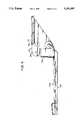
- FIG. 2is a side view of the keyboard support.
- FIG. 3is an exploded perspective view of the keyboard support apparatus.
- FIG. 4is a side view of a second embodiment of the mounting method.
- FIGS. 5, 5A, 5B, 5C and 6, 6A, 6B, 6Care comparative illustrations of the subject keyboard support and positioning system and the prior art.
- FIG. 1is a top view illustrating the relationship of the various elements of the keyboard positioning system.
- a computer monitor 10is positioned on a computer table or desk surface 12.
- Computer monitor 10is in communication with a central processing unit (not shown) which may be located in close proximity to the monitor or at a remote location. The operator would normally be located in a seated position facing the monitor.
- Applicant's keyboard positioning systempositions a keyboard support platform 14 and palm rest 16 between the operator and the monitor 10. The structure of keyboard support platform 14 and palm rest 16 will be more fully understood with detailed reference to FIGS. 2 and 3 which are addressed hereafter.
- a document holder 18so as to position documents in an easy-to-read location vis-a-vis monitor 10 and the operator so as to facilitate the entry of the data.
- the operatormay have software which permits or requires the use of a mouse in order to selectively transfer data through visual commands provided by the mouse on the monitor screen.
- a mouse pad 20is located in proximity to the video monitor 10.
- Document holder 18 and mouse pad 20are designed to be selectively exchanged with each other from the right-hand side to the left-hand side to the computer monitor depending upon the preferred manual dexterity of the operator. When not used in conjunction with a mouse, mouse pad 20 provides a writing surface for the operator.
- Keyboard support platform 14is adjustable in height relative to the operator and the computer monitor 10 and is adjustable in angular tilt with respect to the operator. These adjustable characteristics of keyboard support platform 14 are more fully understood with reference to FIGS. 2 and 3.
- FIG. 2is a side elevational view of a first embodiment of keyboard support platform 14.
- Three main elementscomprise keyboard support platform 14, first, a bracket assembly 22 for securing keyboard support platform 14 to a desk or table support surface 12; a keyboard support surface 24 securable to bracket 22 and angularly pivotal about a pivot point 30 on bracket assembly 22, support surface 24 being generally rectangular in nature having an area and dimension substantially equal to that of a standard computer keyboard: and finally, palm rest 16 which is secured to the lateral edge of keyboard support platform 14 opposite bracket 22.
- Bracket assembly 22is centrally positioned with respect to keyboard support platform 14. Bracket assembly 22 is comprised of a stationary member 26 and a movable member 28 which pivots with respect to stationary member 26 about pivot point 30. Stationary member 26 has a generally-rectangular receiving slot 32 positioned proximate to its upper edge 34. Receiving slot 32 is designed to receive and engage the edge of a computer workstand or table top. Stationary member 26 would be secured to the computer worktable or desk top by means of a friction fastener 36 secured to an operable thumb screw 38 positioned at the lower end 40 of bracket assembly 22.
- Fastening member 36is rotatably movable along its vertical axis within rectangular slot 32 by means of thumbscrew 38 in order to frictionally engage the underside of the computer workstand or table, the upper surface of the workstand or table being engaged by the interior upper surface of rectangular slot 32.
- stationary bracket member 26is of such dimension in order to provide a stable and secure frictional engagement with the computer workstand or table top when fastening member 36 is firmly secured to the underside thereof.
- stationary member 26 of bracket assembly 22would be positioned on the computer workstand or table top and centered on the computer monitor.
- Movable member 28 of bracket assembly 22 which pivots about pivot point 30has an arcuate channel 29 positioned therein for engagement with tilt lever control 42.
- Tilt lever control 42comprises a shaft passing through stationary member 26 and movable member 28 of bracket assembly 22.
- the shaft member and arcuate slot in movable member 28cooperate to permit keyboard support platform 14 to be rotated about pivot point 30 in order to achieve a desired degree of angular tilt.
- tilt lever control 42is engageable from a locked to an unlocked position by means of lever 42 in conjunction with a concentric sleeve mounted on its shaft to engage the arcuate slot 29, within movable member 28. This allows the operator to disengage the tilt lever control 42 from a locked position, adjust the angle of tilt of keyboard support surface 24 and then to reenage the locking mechanism of tilt control lever 42, and its associated shaft with the arcuate channel 20 within movable member 28.
- a centrally-positioned height adjustment knob 50cooperative with movable member 28 and keyboard support platform 14 permits the raising and lowering of keyboard support surface 24 so as to adjust for the proper height of the operator when in a sitting position. Height adjustment knob 50 is more readily discernable with reference to FIG. 3 discussed hereafter.
- Palm rest 16is located on the opposite side of keyboard support surface 24 from bracket assembly 22. Palm rest 16 has an upper surface 60 that the operator's wrist and lower palm would rest during operation. The surface is generally smooth to permit easy movement of the hands and broad enough and contoured enough to eliminate any pinch or pressure points that would restrict circulation or compress nerve tissue.
- surface 60 of palm rest 16would be made of plastic or another suitable material that is purposely a poor conductor of heat such that it will not draw heat from the operator causing discomfort. It would further restrict electrostatic discharge, extremely low field and very low field discharges from the body.
- FIG. 3is a front exploded view in partial perspective of the keyboard support apparatus and ancillary utilities which will aid in understanding the cooperative characteristics of the structural elements.
- Stationary member 26 of bracket assembly 22, having a generally U-shaped receiving slot 32would be positioned in securable relationship with a desk or table top 12 (not shown).
- Thumb screw 38 in cooperation with friction fastener 36 (not shown)would secure stationary member 26 to the table or desk top.
- Stationary member 26may include a reinforcing sleeve 31 which conforms to the shape of U-shaped receiving slot 32 and which would be secured therein. Reinforcing sleeve 31 would provide additional strength to receiving slot 32 in light of the weight which it would support and to ensure a secure fit with the table or desk top.
- Movable member 28 of bracket assembly 22is secured in pivotal relationship with stationary member 26 by means of tilt control lever 42 secured to a pivot bolt 43 passing through stationary member 26 and movable member 28.
- tilt control lever 42secured to a pivot bolt 43 passing through stationary member 26 and movable member 28.
- Tilt control lever 42would then be rotated in the opposite direction to reachieve the compression engagement and fix the relative relationship between stationary member 26 and movable member 28.
- Support platform 14is slidably secured on movable member 28 by means of a height adjustment knob 50 and a front mounting plate 51.
- Front mounting plate 51has lateral vertical ribs 53 which are engageable with lateral vertical receiving slots 55 in movable member 28.
- Movable member 28has a centrally-disposed vertical slot 57 in alignment with a centrally-disposed aperture 59 on front mounting plate 51.
- height adjustment knob 50having a threaded bolt extension, passes through aperture 59 and receiving slot 57 in movable member 28 and is secured by a shoulder bolt. This permits the rotation of adjustment knob 50 to release compression between front mounting plate 51 and movable member 28 and allows keyboard support platform 14 to be moved in a vertical plane to obtain the optimum height adjustment for the user.
- Adjustment knob 50is then rotated in the reverse direction to reenage the compression engagement between movable member 28 and front mounting plate 51.
- the cooperation between vertical lateral ribs 53 and receiving slots 55aid in maintaining the alignment of keyboard support platform 14 and further aid in supporting and guiding keyboard support platform 14 when height adjustment is required.
- Keyboard support platform 14 and its support surface 24can thereby be selectively positioned to accommodate the physiological parameters of the user.
- Support surface 24can thereby be selectively positioned to accommodate the physiological parameters of the user. Additionally, support surface 24 may have positioned thereon, one or more anti-skid pads 57 which would be composed of a friction-like substance such as rubber or latex, which would prevent the movement of the keyboard which would be positioned thereon. Palm rest 16 is illustrated with respect no its relationship to support surface 24.
- keyboard support surface 24which provides support for the computer keyboard may also be equipped with one or more anti-skid pads 62 which would be composed of a friction-like substance such as rubber or latex and which would prevent the movement of the keyboard which would be positioned thereon, during operation.
- palm rest 16as illustrated in FIG. 3, is secured to keyboard support platform 14 by means of threaded fasteners extending upwardly from the underside of keyboard support platform 14 and engaging threaded receiving slots (not shown) on the underside of palm rest 16. The relationship between the height of palm rest 16 and the keyboard will be addressed with respect to illustrations following hereafter.
- ancillary utilities associated with the keyboard support platform 14are also illustrated in FIG. 3. These ancillary utilities which include document holder 18 and mouse pad 20 may be selectively employed with keyboard support platform 14 by means of utility plate 80.
- Utility plate 80would be generally planer having a depending peripheral wall 82 and an extension tongue 84. Extension tongue 84 would be engageable between receiving slot 32 and the top of the table top or desk and secured by fastener 36 to maintain utility platform 80 in position on desk or table top 12 and in alignment with monitor 10.
- Utility platform 80cooperates with mouse pad 20 through the interlocking of peripheral wall 82 of utility platform 80 with edge flange 86 of mouse platform 85 which supports mouse pad 20.
- Mouse platform 85is constructed with two edge flanges 86 in order that the operator may position the mouse platform 85 on either the right-hand side or left-hand side of monitor 10 and utility plate 80, depending upon the user's preference.
- Document holder 18would be secured to utility platform 80 in a similar manner, on the opposing side from mouse platform 85.
- Document holder 18would be comprised of a planer arcuate base 90 having interlocking flanges 92 at the ends thereof for selective engagement with utility platform 80 and its peripheral wall 82.
- arcuate planer base 90There would be disposed on arcuate planer base 90, an arcuate slot 91 for slidable receipt of fastening means 94 which would secure vertical support post 96 in perpendicular relationship with arcuate base 90 and would permit vertical support post 96 to be positioned in slidable relationship and pivotal relationship with arcuate support base 90 along arcuate slot 91.
- Document support post 96would support document holder plate 98 in a vertical relationship which would allow support ribs 100 formed on the rear side of document support plate 98 to slidably engage a height adjustment slot 102 in vertical support post 96 to allow the operator or user to adjust document support plate 98 upwardly or downwardly on vertical support post 96 in order to achieve the proper eye contact angle with the document being transposed into the computer.
- Document holder 18thus permits the user to move the document in an arcuate and pivotal fashion to obtain the optimum horizontal angle for viewing the document and also to move the document in a vertical fashion to obtain the optimum vertical plane for viewing the document.
- Document support plate 98may also be equipped with a document retainer and line guide 104 slidably adjustable along the lateral edges of document support plate 98.
- the design of arcuate base plate 90 for document holder 18 and mouse platform 85are such that they are interchangeable from the right hand to the left-hand side of the utility plate 80 depending upon the user's preference.
- the operatortherefore has two adjustments available with respect to keyboard support platform 14 as illustrated in FIG. 3, for obtaining a comfortable, posture-correct position in front of the keyboard and computer monitor with the simultaneous elimination of fatigue and stress points.
- These two adjustmentsare the height adjustment of keyboard support platform 14 by means of adjustment 50 and the angular tilt of keyboard support platform 14 by means of tilt control lever 42 in cooperation with stationary member 26 and movable member 28 of bracket 22.
- the operatoralso has available the adjustments with respect to location of the mouse pad and the document holder and the vertical and horizontal relationship of the document holder with respect to the operator's height and line of sight.
- FIG. 4there is illustrated a second embodiment of the keyboard positioning system.
- This embodimentis identical to that illustrated in FIG. 2 with the exception of the mounting method.
- the embodiment illustrated in FIG. 4discloses a keyboard support platform 14A in which stationary member 26A no longer has a rectangular receiving slot 32 and fastener 36 to maintain its position on the computer workstation table or desk top.
- stationary member 26Ahas positioned along its upper surface 34A, an extended flange 37A for engagement with a carriage rail 90 which is secured to the underside of the computer workstation table or desk top. This allows the keyboard support platform 14A to be withdrawn from under the computer workstation or table for use and pushed in a retracted mode beneath the computer workstation or table when not in use.
- FIG. 5illustrates the advantages of Applicant's keyboard support system as it relates to the relief or reduction of carpal tunnel syndrome and to the benefits achieved with respect to the positioning of the ancillary utilities in relationship to Applicant's keyboard support system.
- FIG. 5Athere is illustrated a side view of a human hand illustrating the differences between the neutral position as shown by the solid lines, and an extension position in which the hand is turned upwardly thereby creating tension on the wrist, and the flexion position in which the hand is tilted downwardly, again causing tension in the individual's wrist.
- the desirable position for maintenance of the hand when utilizing computer keyboardsis that of the neutral position. This prevents undue pressure and tension at the wrist which can lead to carpal tunnel syndrome and other maladies.
- FIG. 5Athere is illustrated a side view of a human hand illustrating the differences between the neutral position as shown by the solid lines, and an extension position in which the hand is turned upwardly thereby creating tension on the wrist, and the flexion position in which the hand is tilted downward
- FIG. 5Billustrates the position of the user with respect to Applicant's keyboard support system.
- the wrist and handis maintained in a neutral position as a result of the angular tilt and height of the keyboard as discussed previously.
- the palm rest 16is positioned to a conforming height which is substantially equal to the front edge of the computer keyboard. This permits the user to rest the palm of the hand on the palm rest with the fingers extended over the keyboard. The positioning results in a neutral position between the hand and wrist of the user.
- This positionis medically desirable to prevent the onset of carpal tunnel syndrome or to lessen its effects in individuals or users who have already experienced the problem.
- This positionalso provides for greater comfort and relaxation of the user or operator as compared to those positions disclosed in FIG.
- FIG. 6which represent operating standards presently in existence or makeshift attempts to relieve the problem.
- FIG. 6Aillustrates the user's wrist and hand in an extension position.
- FIG. 6Balso represents and illustrates the user or operator's hand in an extension position contributing to the tension on the wrist.
- FIG. 6Cillustrates an attempt to relieve the tension on the user or operator's wrist by tilting the keyboard downwardly. However, it can be readily seen that this results in a flexion of the user or operator's wrist which also places tension on the user or operator's wrist.
- the position as shown in FIG. 5Bwhich is achieved as a result of the angular tilt and height adjustments available through Applicant's structure, allows the user or operator to obtain a neutral wrist position.
- This neutral wrist position achieved by Applicant's keyboard support system 14further enhances the productivity of the user or operator and relieves tension and fatigue when coupled with the auxiliary utilities of Applicant's system as illustrated in FIG. 5C which illustrates these utilities being positioned in cooperative relationship with respect to the keyboard support system to allow for posture-correct positioning of the user or operator, together with the user or operator's ability to position the document support holder 18 within an angularly minimal line of sight in relationship to the computer monitor.
- the overall systemtherefore provides for a relaxed and tension-free position environment, yet still provides the user or operator access to all utilities necessary in the performance of their tasks.
Landscapes
- Input From Keyboards Or The Like (AREA)
Abstract
Description
Claims (6)
Priority Applications (3)
| Application Number | Priority Date | Filing Date | Title |
|---|---|---|---|
| US07/871,108US5351897A (en) | 1992-04-20 | 1992-04-20 | Adjustable ergonomic support for computer keyboards |
| US08/198,890US5582375A (en) | 1992-04-20 | 1994-02-18 | Adjustable ergonomic support for computer keyboards |
| US09/306,622US6148739A (en) | 1992-04-20 | 1999-05-06 | Adjustable ergonomic support for computer keyboards |
Applications Claiming Priority (1)
| Application Number | Priority Date | Filing Date | Title |
|---|---|---|---|
| US07/871,108US5351897A (en) | 1992-04-20 | 1992-04-20 | Adjustable ergonomic support for computer keyboards |
Related Child Applications (1)
| Application Number | Title | Priority Date | Filing Date |
|---|---|---|---|
| US08/198,890Continuation-In-PartUS5582375A (en) | 1992-04-20 | 1994-02-18 | Adjustable ergonomic support for computer keyboards |
Publications (1)
| Publication Number | Publication Date |
|---|---|
| US5351897Atrue US5351897A (en) | 1994-10-04 |
Family
ID=25356748
Family Applications (1)
| Application Number | Title | Priority Date | Filing Date |
|---|---|---|---|
| US07/871,108Expired - Fee RelatedUS5351897A (en) | 1992-04-20 | 1992-04-20 | Adjustable ergonomic support for computer keyboards |
Country Status (1)
| Country | Link |
|---|---|
| US (1) | US5351897A (en) |
Cited By (55)
| Publication number | Priority date | Publication date | Assignee | Title |
|---|---|---|---|---|
| US5443237A (en)* | 1994-05-06 | 1995-08-22 | Stadtmauer; Seymour H. | Computer keyboard support system |
| US5509628A (en)* | 1995-06-09 | 1996-04-23 | Noble; Bruce | Ergonomic support for keyboard and computer mouse platform |
| US5528796A (en)* | 1995-06-06 | 1996-06-25 | Proformix, Inc. | Hinged connection for a tilt up device |
| US5533820A (en)* | 1993-07-28 | 1996-07-09 | Ambrose; Frederic C. | Keyboard positioning system |
| US5567067A (en)* | 1991-02-01 | 1996-10-22 | Ambrose; Frederic C. | Keyboard positioning system |
| US5582375A (en)* | 1992-04-20 | 1996-12-10 | Martin; Michael | Adjustable ergonomic support for computer keyboards |
| US5595428A (en)* | 1995-07-28 | 1997-01-21 | Huang; Michael | Ergonomic keyboard drawer |
| US5605311A (en)* | 1994-09-20 | 1997-02-25 | Mcgrath; Michael | Upper torso support for a workstation |
| US5636822A (en)* | 1995-08-09 | 1997-06-10 | Steelcase Inc. | Computer mouse support |
| US5704698A (en)* | 1996-02-07 | 1998-01-06 | Lin; Chin-Chih | Keyboard slide structure with removable palm rest and slide rail means |
| US5722624A (en)* | 1996-05-29 | 1998-03-03 | Weber Knapp Company | Laptop computer support |
| US5735222A (en)* | 1994-02-18 | 1998-04-07 | Webb; Sharon L. | Vertically adjustable detachable keyboard tray |
| WO1998023185A1 (en)* | 1996-11-26 | 1998-06-04 | Bohman Information I Hudiksvall Ab | Keyboard holder |
| US5765797A (en)* | 1995-12-12 | 1998-06-16 | Greene; H. Peter | Articulated support for computers and the like |
| US5810301A (en)* | 1994-09-20 | 1998-09-22 | Mcgrath; Michael | Upper torso support for a workstation |
| US5820085A (en)* | 1996-09-20 | 1998-10-13 | Or Computer Keyboards Ltd. | Hand support with positioner for use with computer input devices |
| US5826842A (en)* | 1995-01-13 | 1998-10-27 | Or Computer Keyboards Ltd. | Ergonomic computer mouse workstation |
| US5833378A (en)* | 1996-05-29 | 1998-11-10 | Gibson; Marc E. | Collapsible typing keyboard tray |
| WO1998049922A1 (en)* | 1997-05-01 | 1998-11-12 | Ael Pty Ltd. | Forearm support |
| US5836562A (en)* | 1996-08-16 | 1998-11-17 | Fellowes Manufacturing Company | Mounting device for an apparatus for supporting a keyboard |
| US5848773A (en)* | 1997-04-17 | 1998-12-15 | Bourassa; David O. | Mouse pad support pedestal |
| WO1999008566A1 (en)* | 1997-08-12 | 1999-02-25 | Cotterill Michael J | A desk accessory support |
| US5881984A (en)* | 1997-06-20 | 1999-03-16 | Lin; Chin-Chih | Dimensional adjusting device for computer keyboards racks |
| US5924664A (en)* | 1997-03-12 | 1999-07-20 | Ergo View Technologies Corp. | Keyboard support mechanism |
| US5924807A (en)* | 1994-09-29 | 1999-07-20 | Flex-Rest, Llc | Securable device for computer apparatus |
| US5961231A (en)* | 1994-09-16 | 1999-10-05 | Flex-Rest, Llc | Keyboard positioning system |
| US6076785A (en)* | 1996-02-29 | 2000-06-20 | Innovative Office Products, Inc. | Ergonomic sit/stand keyboard support mechanism |
| US6079676A (en)* | 1996-12-09 | 2000-06-27 | West Shore Services, Inc. | Adjustable mouse pad support |
| US6129318A (en)* | 1996-01-11 | 2000-10-10 | Or Computer Keyboards Ltd. | Ergonomic computer mouse workstation |
| US6135405A (en)* | 1995-11-22 | 2000-10-24 | Steelcase Development Inc. | Tilt lockout for articulated keyboard supports |
| US6148739A (en)* | 1992-04-20 | 2000-11-21 | 1320236 Ontario Inc. | Adjustable ergonomic support for computer keyboards |
| AU735153B2 (en)* | 1997-08-12 | 2001-07-05 | Fjp Manufacturing Pty Limited | A desk accessory support |
| US6273382B1 (en) | 1999-09-30 | 2001-08-14 | Gregory L. Pemberton | Adjustable tilt-down keyboard support device |
| US6293508B1 (en) | 1999-01-19 | 2001-09-25 | Group Dekko Services, Llc. | Keyboard support system |
| USD452509S1 (en) | 2000-11-10 | 2001-12-25 | Allsop, Inc. | Computer mouse ramp |
| US6390432B1 (en) | 1999-03-05 | 2002-05-21 | Knape & Vogt Manufacturing Company | Adjustable and detachable mouse pad support and keyboard support having the same |
| US6409127B1 (en) | 1998-10-27 | 2002-06-25 | Knape & Vogt Manufacturing Co. | Adjustable keyboard support mechanism |
| US6419197B2 (en) | 1999-01-19 | 2002-07-16 | Group Dekko Services, Llc | Keyboard support system |
| US6467737B1 (en) | 2000-09-22 | 2002-10-22 | David Dorantes | Adjustable arm rest for use with a personal computer |
| US6526896B2 (en)* | 2001-02-05 | 2003-03-04 | Inscape Corporation | Multi-positional mouse pad |
| US6527235B1 (en) | 1997-08-15 | 2003-03-04 | Michael John Cotterill | Desk accessory support |
| US6579022B1 (en)* | 2000-03-09 | 2003-06-17 | Active Input Solutions, Llc | Keyboard support platform |
| US20050105255A1 (en)* | 2003-11-18 | 2005-05-19 | 3M Innovative Properties Company | Adjustable keyboard support assembly |
| US6938866B2 (en) | 2003-11-18 | 2005-09-06 | 3M Innovative Properties Company | Adjustable keyboard support assembly method of use |
| US20070001077A1 (en)* | 2005-06-30 | 2007-01-04 | 3M Innovative Properties Company | Adjustable keyboard support assembly |
| US20100224750A1 (en)* | 2009-03-04 | 2010-09-09 | Nimrod Webber | Loudspeaker tilting adapter |
| US8740166B2 (en) | 2011-02-17 | 2014-06-03 | Fellowes, Inc. | Keyboard and mouse support |
| US8864091B1 (en)* | 2013-04-12 | 2014-10-21 | Filco/USA, Inc. | Articulating keyboard and mouse platform system |
| USD822676S1 (en)* | 2017-02-17 | 2018-07-10 | Creator's Stained Glass, Inc. | Computer mouse pad shelf |
| EP3191762A4 (en)* | 2014-09-11 | 2018-07-11 | Thermogenesis Group, Inc. | Ergonomic keyboard and peripheral positioning system |
| US20190110590A1 (en)* | 2017-10-13 | 2019-04-18 | Loctek Ergonomic Technology Corp. | Lifting platform with a sliding keyboard holder |
| US20200196750A1 (en)* | 2018-12-19 | 2020-06-25 | Tod Zimmerman | Tray attachment assembly |
| US10881222B1 (en)* | 2020-05-21 | 2021-01-05 | Stephanie Van Keane London | Apparatus to facilitate physical distancing |
| CN113176829A (en)* | 2021-05-12 | 2021-07-27 | 深圳市金拓达科技有限公司 | Single-hand game keyboard |
| US20230331032A1 (en)* | 2022-04-19 | 2023-10-19 | Tony Argueta | Attachment assembly including fastening mechanisms |
Citations (3)
| Publication number | Priority date | Publication date | Assignee | Title |
|---|---|---|---|---|
| US3991961A (en)* | 1975-03-03 | 1976-11-16 | Platzer Jr George E | Collapsible support structure |
| US4706919A (en)* | 1986-12-17 | 1987-11-17 | Haworth, Inc. | Keyboard support with automatic lowering mechanism |
| US4949650A (en)* | 1989-07-31 | 1990-08-21 | Allard David D | Table having a part of which is adjustable upwardly |
- 1992
- 1992-04-20USUS07/871,108patent/US5351897A/ennot_activeExpired - Fee Related
Patent Citations (3)
| Publication number | Priority date | Publication date | Assignee | Title |
|---|---|---|---|---|
| US3991961A (en)* | 1975-03-03 | 1976-11-16 | Platzer Jr George E | Collapsible support structure |
| US4706919A (en)* | 1986-12-17 | 1987-11-17 | Haworth, Inc. | Keyboard support with automatic lowering mechanism |
| US4949650A (en)* | 1989-07-31 | 1990-08-21 | Allard David D | Table having a part of which is adjustable upwardly |
Cited By (68)
| Publication number | Priority date | Publication date | Assignee | Title |
|---|---|---|---|---|
| US5709489A (en)* | 1991-02-01 | 1998-01-20 | Ambrose; Frederic C. | Keyboard positioning system |
| US5567067A (en)* | 1991-02-01 | 1996-10-22 | Ambrose; Frederic C. | Keyboard positioning system |
| US5582375A (en)* | 1992-04-20 | 1996-12-10 | Martin; Michael | Adjustable ergonomic support for computer keyboards |
| US6148739A (en)* | 1992-04-20 | 2000-11-21 | 1320236 Ontario Inc. | Adjustable ergonomic support for computer keyboards |
| US5533820A (en)* | 1993-07-28 | 1996-07-09 | Ambrose; Frederic C. | Keyboard positioning system |
| US5735222A (en)* | 1994-02-18 | 1998-04-07 | Webb; Sharon L. | Vertically adjustable detachable keyboard tray |
| US5443237A (en)* | 1994-05-06 | 1995-08-22 | Stadtmauer; Seymour H. | Computer keyboard support system |
| US5961231A (en)* | 1994-09-16 | 1999-10-05 | Flex-Rest, Llc | Keyboard positioning system |
| US5605311A (en)* | 1994-09-20 | 1997-02-25 | Mcgrath; Michael | Upper torso support for a workstation |
| US5810301A (en)* | 1994-09-20 | 1998-09-22 | Mcgrath; Michael | Upper torso support for a workstation |
| US5924807A (en)* | 1994-09-29 | 1999-07-20 | Flex-Rest, Llc | Securable device for computer apparatus |
| US5826842A (en)* | 1995-01-13 | 1998-10-27 | Or Computer Keyboards Ltd. | Ergonomic computer mouse workstation |
| US5528796A (en)* | 1995-06-06 | 1996-06-25 | Proformix, Inc. | Hinged connection for a tilt up device |
| US5509628A (en)* | 1995-06-09 | 1996-04-23 | Noble; Bruce | Ergonomic support for keyboard and computer mouse platform |
| US5595428A (en)* | 1995-07-28 | 1997-01-21 | Huang; Michael | Ergonomic keyboard drawer |
| US5636822A (en)* | 1995-08-09 | 1997-06-10 | Steelcase Inc. | Computer mouse support |
| US6135405A (en)* | 1995-11-22 | 2000-10-24 | Steelcase Development Inc. | Tilt lockout for articulated keyboard supports |
| US6343775B1 (en) | 1995-11-22 | 2002-02-05 | Steelcase Development Corporation | Keyboard support with quick connect |
| US5765797A (en)* | 1995-12-12 | 1998-06-16 | Greene; H. Peter | Articulated support for computers and the like |
| US6129318A (en)* | 1996-01-11 | 2000-10-10 | Or Computer Keyboards Ltd. | Ergonomic computer mouse workstation |
| US5704698A (en)* | 1996-02-07 | 1998-01-06 | Lin; Chin-Chih | Keyboard slide structure with removable palm rest and slide rail means |
| US6076785A (en)* | 1996-02-29 | 2000-06-20 | Innovative Office Products, Inc. | Ergonomic sit/stand keyboard support mechanism |
| US5833378A (en)* | 1996-05-29 | 1998-11-10 | Gibson; Marc E. | Collapsible typing keyboard tray |
| US5722624A (en)* | 1996-05-29 | 1998-03-03 | Weber Knapp Company | Laptop computer support |
| US5836562A (en)* | 1996-08-16 | 1998-11-17 | Fellowes Manufacturing Company | Mounting device for an apparatus for supporting a keyboard |
| US5820085A (en)* | 1996-09-20 | 1998-10-13 | Or Computer Keyboards Ltd. | Hand support with positioner for use with computer input devices |
| WO1998023185A1 (en)* | 1996-11-26 | 1998-06-04 | Bohman Information I Hudiksvall Ab | Keyboard holder |
| US6264149B1 (en) | 1996-11-26 | 2001-07-24 | Bohman Information I Hudiksvall Ab | Keyboard holder |
| US6079676A (en)* | 1996-12-09 | 2000-06-27 | West Shore Services, Inc. | Adjustable mouse pad support |
| US7841570B2 (en) | 1997-03-12 | 2010-11-30 | Humanscale Corporation | Keyboard support mechanism |
| US5924664A (en)* | 1997-03-12 | 1999-07-20 | Ergo View Technologies Corp. | Keyboard support mechanism |
| US7841569B2 (en) | 1997-03-12 | 2010-11-30 | Humanscale Corporation | Keyboard support mechanism |
| US20060157628A1 (en)* | 1997-03-12 | 2006-07-20 | George Mileos | Keyboard support mechanism |
| US6883764B1 (en) | 1997-03-12 | 2005-04-26 | Humanscale Corp. | Keyboard support mechanism |
| US5848773A (en)* | 1997-04-17 | 1998-12-15 | Bourassa; David O. | Mouse pad support pedestal |
| WO1998049922A1 (en)* | 1997-05-01 | 1998-11-12 | Ael Pty Ltd. | Forearm support |
| US5881984A (en)* | 1997-06-20 | 1999-03-16 | Lin; Chin-Chih | Dimensional adjusting device for computer keyboards racks |
| AU735153B2 (en)* | 1997-08-12 | 2001-07-05 | Fjp Manufacturing Pty Limited | A desk accessory support |
| WO1999008566A1 (en)* | 1997-08-12 | 1999-02-25 | Cotterill Michael J | A desk accessory support |
| US6527235B1 (en) | 1997-08-15 | 2003-03-04 | Michael John Cotterill | Desk accessory support |
| US6409127B1 (en) | 1998-10-27 | 2002-06-25 | Knape & Vogt Manufacturing Co. | Adjustable keyboard support mechanism |
| US6293508B1 (en) | 1999-01-19 | 2001-09-25 | Group Dekko Services, Llc. | Keyboard support system |
| US6419197B2 (en) | 1999-01-19 | 2002-07-16 | Group Dekko Services, Llc | Keyboard support system |
| US6390432B1 (en) | 1999-03-05 | 2002-05-21 | Knape & Vogt Manufacturing Company | Adjustable and detachable mouse pad support and keyboard support having the same |
| US6273382B1 (en) | 1999-09-30 | 2001-08-14 | Gregory L. Pemberton | Adjustable tilt-down keyboard support device |
| US6579022B1 (en)* | 2000-03-09 | 2003-06-17 | Active Input Solutions, Llc | Keyboard support platform |
| US6467737B1 (en) | 2000-09-22 | 2002-10-22 | David Dorantes | Adjustable arm rest for use with a personal computer |
| USD452509S1 (en) | 2000-11-10 | 2001-12-25 | Allsop, Inc. | Computer mouse ramp |
| US6526896B2 (en)* | 2001-02-05 | 2003-03-04 | Inscape Corporation | Multi-positional mouse pad |
| US20050105255A1 (en)* | 2003-11-18 | 2005-05-19 | 3M Innovative Properties Company | Adjustable keyboard support assembly |
| US6938866B2 (en) | 2003-11-18 | 2005-09-06 | 3M Innovative Properties Company | Adjustable keyboard support assembly method of use |
| US7113393B2 (en) | 2003-11-18 | 2006-09-26 | 3M Innovative Properties Company | Adjustable keyboard support assembly |
| US20070001077A1 (en)* | 2005-06-30 | 2007-01-04 | 3M Innovative Properties Company | Adjustable keyboard support assembly |
| US7575205B2 (en)* | 2005-06-30 | 2009-08-18 | 3M Innovative Properties Company | Adjustable keyboard support assembly |
| US20100224750A1 (en)* | 2009-03-04 | 2010-09-09 | Nimrod Webber | Loudspeaker tilting adapter |
| US8740166B2 (en) | 2011-02-17 | 2014-06-03 | Fellowes, Inc. | Keyboard and mouse support |
| US8864091B1 (en)* | 2013-04-12 | 2014-10-21 | Filco/USA, Inc. | Articulating keyboard and mouse platform system |
| EP3191762A4 (en)* | 2014-09-11 | 2018-07-11 | Thermogenesis Group, Inc. | Ergonomic keyboard and peripheral positioning system |
| USD822676S1 (en)* | 2017-02-17 | 2018-07-10 | Creator's Stained Glass, Inc. | Computer mouse pad shelf |
| US20190110590A1 (en)* | 2017-10-13 | 2019-04-18 | Loctek Ergonomic Technology Corp. | Lifting platform with a sliding keyboard holder |
| US10743655B2 (en)* | 2017-10-13 | 2020-08-18 | Loctek Ergonomic Technology Corp. | Lifting platform with a sliding keyboard holder |
| US10945520B2 (en)* | 2017-10-13 | 2021-03-16 | Loctek Inc. | Lifting platform with a sliding keyboard holder |
| US20200196750A1 (en)* | 2018-12-19 | 2020-06-25 | Tod Zimmerman | Tray attachment assembly |
| US10842262B2 (en)* | 2018-12-19 | 2020-11-24 | Tod Zimmerman | Tray attachment assembly |
| US10881222B1 (en)* | 2020-05-21 | 2021-01-05 | Stephanie Van Keane London | Apparatus to facilitate physical distancing |
| CN113176829A (en)* | 2021-05-12 | 2021-07-27 | 深圳市金拓达科技有限公司 | Single-hand game keyboard |
| CN113176829B (en)* | 2021-05-12 | 2022-06-24 | 深圳市金拓达科技有限公司 | Single-hand game keyboard |
| US20230331032A1 (en)* | 2022-04-19 | 2023-10-19 | Tony Argueta | Attachment assembly including fastening mechanisms |
Similar Documents
| Publication | Publication Date | Title |
|---|---|---|
| US5351897A (en) | Adjustable ergonomic support for computer keyboards | |
| US5582375A (en) | Adjustable ergonomic support for computer keyboards | |
| US5056743A (en) | Arm support system | |
| US5183230A (en) | Computer keyboard support with padded wrist support | |
| US5112020A (en) | Keyboard stand | |
| US6454224B1 (en) | Forearm and wrist support assembly for keyboard user | |
| EP0495040B1 (en) | Apparatus and method for reducing repetitive or maintained stress injuries | |
| US5158256A (en) | Keyboard accessory | |
| US5857415A (en) | Ergonomic computer workstation and method of using | |
| US5398896A (en) | Dynamic support device for keyboards | |
| US5522323A (en) | Ergonimic computer workstation and method of using | |
| US5678800A (en) | Computer mouse pad having inclined surfaces | |
| US5311210A (en) | Ergonomic keyboard and operator's chair | |
| US5143422A (en) | Adjustable active arm support for keyboard operators | |
| US6088022A (en) | Spherical keyboard with built-in mouse | |
| US5072905A (en) | Wrist and forearm support apparatus | |
| US5108057A (en) | Free sliding hand rest | |
| US5004196A (en) | Keyboard accessory | |
| US5661605A (en) | Computer keyboard | |
| US6148739A (en) | Adjustable ergonomic support for computer keyboards | |
| US5201485A (en) | Apparatus and method for reducing repetitive or maintained stress injuries | |
| US6059470A (en) | Adjustable, curved keyboard | |
| US5709489A (en) | Keyboard positioning system | |
| EP0251643A2 (en) | Arm-rest keyboard | |
| US5662422A (en) | Bifurcated keyboard arrangement |
Legal Events
| Date | Code | Title | Description |
|---|---|---|---|
| AS | Assignment | Owner name:PROFORMIX, INC., NEW JERSEY Free format text:ASSIGNMENT OF ASSIGNORS INTEREST;ASSIGNOR:MARTIN, MICHAEL G.;REEL/FRAME:007644/0668 Effective date:19950206 | |
| FEPP | Fee payment procedure | Free format text:PAYOR NUMBER ASSIGNED (ORIGINAL EVENT CODE: ASPN); ENTITY STATUS OF PATENT OWNER: SMALL ENTITY | |
| AS | Assignment | Owner name:PISANI, B. MICHAEL, NEW JERSEY Free format text:ASSIGNMENT OF ASSIGNORS INTEREST;ASSIGNORS:MARTING, MICHAEL G.;PROFORMIX, INC.;REEL/FRAME:008512/0616 Effective date:19970430 | |
| AS | Assignment | Owner name:NEW JERSEY ECONOMIC DEVELOPMENT AUTHORITY, NEW JER Free format text:SECURITY AGREEMENT;ASSIGNORS:MARTIN, MICHAEL G.;PROFORMIX, INC.;REEL/FRAME:008512/0894 Effective date:19970429 Owner name:CARNEGIE BANK, N.A., NEW JERSEY Free format text:SECURITY AGREEMENT;ASSIGNORS:MARTIN, MICHAEL G.;PROFORMIX, INC.;REEL/FRAME:008512/0894 Effective date:19970429 | |
| AS | Assignment | Owner name:PISANI, B. MICHAEL, NEW JERSEY Free format text:CORRECTED ASSIGNMENT TO CHANGE NATURE OF CONVEYANCE FROM AN ASSIGNMENT TO A SECURITY AGREEMENT. PREVIOUSLY RECORDED ON REEL 8512, FRAME 0616.;ASSIGNORS:MARTIN, MICHAEL G.;PROFORMIX, INC.;REEL/FRAME:008650/0511 Effective date:19970430 | |
| FPAY | Fee payment | Year of fee payment:4 | |
| AS | Assignment | Owner name:1320236 ONTARIO INC., CANADA Free format text:ASSIGNMENT OF ASSIGNORS INTEREST;ASSIGNOR:PROFORMIX, INC.;REEL/FRAME:009711/0370 Effective date:19981118 | |
| FPAY | Fee payment | Year of fee payment:8 | |
| FEPP | Fee payment procedure | Free format text:PAYER NUMBER DE-ASSIGNED (ORIGINAL EVENT CODE: RMPN); ENTITY STATUS OF PATENT OWNER: SMALL ENTITY | |
| REMI | Maintenance fee reminder mailed | ||
| LAPS | Lapse for failure to pay maintenance fees | ||
| STCH | Information on status: patent discontinuation | Free format text:PATENT EXPIRED DUE TO NONPAYMENT OF MAINTENANCE FEES UNDER 37 CFR 1.362 | |
| FP | Lapsed due to failure to pay maintenance fee | Effective date:20061004 |