US5351522A - Gas sensor - Google Patents
Gas sensorDownload PDFInfo
- Publication number
- US5351522A US5351522AUS08/147,326US14732693AUS5351522AUS 5351522 AUS5351522 AUS 5351522AUS 14732693 AUS14732693 AUS 14732693AUS 5351522 AUS5351522 AUS 5351522A
- Authority
- US
- United States
- Prior art keywords
- gas
- sensor device
- transmitter
- shaped housing
- receiver
- Prior art date
- Legal status (The legal status is an assumption and is not a legal conclusion. Google has not performed a legal analysis and makes no representation as to the accuracy of the status listed.)
- Expired - Lifetime
Links
- 238000001514detection methodMethods0.000claimsabstractdescription16
- 230000009467reductionEffects0.000claimsdescription8
- 239000004744fabricSubstances0.000claimsdescription6
- 239000007789gasSubstances0.000abstractdescription131
- QVGXLLKOCUKJST-UHFFFAOYSA-Natomic oxygenChemical compound[O]QVGXLLKOCUKJST-UHFFFAOYSA-N0.000abstractdescription45
- 239000001301oxygenSubstances0.000abstractdescription45
- 229910052760oxygenInorganic materials0.000abstractdescription44
- 238000013461designMethods0.000abstractdescription5
- 239000000463materialSubstances0.000description15
- 239000000203mixtureSubstances0.000description14
- 150000001875compoundsChemical class0.000description11
- 238000004382pottingMethods0.000description11
- IJGRMHOSHXDMSA-UHFFFAOYSA-NAtomic nitrogenChemical compoundN#NIJGRMHOSHXDMSA-UHFFFAOYSA-N0.000description7
- 238000004458analytical methodMethods0.000description7
- 238000005259measurementMethods0.000description7
- 239000004033plasticSubstances0.000description7
- 238000000034methodMethods0.000description6
- 238000004364calculation methodMethods0.000description5
- 230000000694effectsEffects0.000description5
- 238000010586diagramMethods0.000description4
- 230000000149penetrating effectEffects0.000description4
- 239000004417polycarbonateSubstances0.000description4
- 229920000515polycarbonatePolymers0.000description4
- 238000007789sealingMethods0.000description4
- 230000015572biosynthetic processEffects0.000description3
- 230000007613environmental effectEffects0.000description3
- 239000006260foamSubstances0.000description3
- 229910052757nitrogenInorganic materials0.000description3
- 230000001225therapeutic effectEffects0.000description3
- 230000008859changeEffects0.000description2
- 238000010276constructionMethods0.000description2
- 230000008878couplingEffects0.000description2
- 238000010168coupling processMethods0.000description2
- 238000005859coupling reactionMethods0.000description2
- 239000013078crystalSubstances0.000description2
- 230000006378damageEffects0.000description2
- 230000001934delayEffects0.000description2
- 229910001882dioxygenInorganic materials0.000description2
- 230000005284excitationEffects0.000description2
- 230000010355oscillationEffects0.000description2
- 210000002268woolAnatomy0.000description2
- 206010002091AnaesthesiaDiseases0.000description1
- 229920000742CottonPolymers0.000description1
- MYMOFIZGZYHOMD-UHFFFAOYSA-NDioxygenChemical compoundO=OMYMOFIZGZYHOMD-UHFFFAOYSA-N0.000description1
- 208000027418Wounds and injuryDiseases0.000description1
- 239000002250absorbentSubstances0.000description1
- 230000037005anaesthesiaEffects0.000description1
- 238000013459approachMethods0.000description1
- 230000035559beat frequencyEffects0.000description1
- 230000008901benefitEffects0.000description1
- 239000003153chemical reaction reagentSubstances0.000description1
- 229910001873dinitrogenInorganic materials0.000description1
- 238000001035dryingMethods0.000description1
- 230000003028elevating effectEffects0.000description1
- 230000008030eliminationEffects0.000description1
- 238000003379elimination reactionMethods0.000description1
- 230000002708enhancing effectEffects0.000description1
- 238000004868gas analysisMethods0.000description1
- 239000008246gaseous mixtureSubstances0.000description1
- 230000036541healthEffects0.000description1
- 230000006872improvementEffects0.000description1
- 208000014674injuryDiseases0.000description1
- 239000011810insulating materialSubstances0.000description1
- 230000002452interceptive effectEffects0.000description1
- 238000012423maintenanceMethods0.000description1
- 238000004519manufacturing processMethods0.000description1
- 230000013011matingEffects0.000description1
- 238000000691measurement methodMethods0.000description1
- 239000002991molded plasticSubstances0.000description1
- 238000005457optimizationMethods0.000description1
- 230000035515penetrationEffects0.000description1
- 230000010363phase shiftEffects0.000description1
- 238000012545processingMethods0.000description1
- 230000001105regulatory effectEffects0.000description1
- 230000006903response to temperatureEffects0.000description1
- 239000004065semiconductorSubstances0.000description1
- 230000035945sensitivityEffects0.000description1
- 239000000126substanceSubstances0.000description1
- 230000000153supplemental effectEffects0.000description1
- 230000002459sustained effectEffects0.000description1
- 239000012209synthetic fiberSubstances0.000description1
- 229920002994synthetic fiberPolymers0.000description1
Images


Classifications
- G—PHYSICS
- G01—MEASURING; TESTING
- G01N—INVESTIGATING OR ANALYSING MATERIALS BY DETERMINING THEIR CHEMICAL OR PHYSICAL PROPERTIES
- G01N29/00—Investigating or analysing materials by the use of ultrasonic, sonic or infrasonic waves; Visualisation of the interior of objects by transmitting ultrasonic or sonic waves through the object
- G01N29/02—Analysing fluids
- G01N29/024—Analysing fluids by measuring propagation velocity or propagation time of acoustic waves
- G—PHYSICS
- G01—MEASURING; TESTING
- G01N—INVESTIGATING OR ANALYSING MATERIALS BY DETERMINING THEIR CHEMICAL OR PHYSICAL PROPERTIES
- G01N29/00—Investigating or analysing materials by the use of ultrasonic, sonic or infrasonic waves; Visualisation of the interior of objects by transmitting ultrasonic or sonic waves through the object
- G01N29/22—Details, e.g. general constructional or apparatus details
- G01N29/24—Probes
- G01N29/2481—Wireless probes, e.g. with transponders or radio links
- G—PHYSICS
- G01—MEASURING; TESTING
- G01N—INVESTIGATING OR ANALYSING MATERIALS BY DETERMINING THEIR CHEMICAL OR PHYSICAL PROPERTIES
- G01N29/00—Investigating or analysing materials by the use of ultrasonic, sonic or infrasonic waves; Visualisation of the interior of objects by transmitting ultrasonic or sonic waves through the object
- G01N29/22—Details, e.g. general constructional or apparatus details
- G01N29/32—Arrangements for suppressing undesired influences, e.g. temperature or pressure variations, compensating for signal noise
- G01N29/326—Arrangements for suppressing undesired influences, e.g. temperature or pressure variations, compensating for signal noise compensating for temperature variations
- G—PHYSICS
- G01—MEASURING; TESTING
- G01N—INVESTIGATING OR ANALYSING MATERIALS BY DETERMINING THEIR CHEMICAL OR PHYSICAL PROPERTIES
- G01N2291/00—Indexing codes associated with group G01N29/00
- G01N2291/02—Indexing codes associated with the analysed material
- G01N2291/021—Gases
- G01N2291/0212—Binary gases
- G—PHYSICS
- G01—MEASURING; TESTING
- G01N—INVESTIGATING OR ANALYSING MATERIALS BY DETERMINING THEIR CHEMICAL OR PHYSICAL PROPERTIES
- G01N2291/00—Indexing codes associated with group G01N29/00
- G01N2291/02—Indexing codes associated with the analysed material
- G01N2291/028—Material parameters
- G01N2291/02881—Temperature
- G—PHYSICS
- G01—MEASURING; TESTING
- G01N—INVESTIGATING OR ANALYSING MATERIALS BY DETERMINING THEIR CHEMICAL OR PHYSICAL PROPERTIES
- G01N2291/00—Indexing codes associated with group G01N29/00
- G01N2291/10—Number of transducers
- G01N2291/102—Number of transducers one emitter, one receiver
Definitions
- This inventionrelates generally to an ultrasonic gas measuring device for detecting and determining the concentration of oxygen within a binary oxygen gas mixture. The concentration of oxygen within a binary gas mixture is then used in therapeutic medicinal applications.
- the inventionincorporates a means for providing a more efficient and precise determination of the concentration of oxygen within a binary gas mixture, such as an oxygen/nitrogen mixture.
- Prior art deviceshave been developed to continuously monitor the ratio of two known gases within a gas mixture.
- a typical example of a binary gas composition to be measuredwould include oxygen/nitrogen mixtures used in the therapeutic administration of oxygen from oxygen concentrators in home health care environments. Additionally, respirators, ventilators, and air/oxygen blenders are commonly used in hospitals requiring known ranges of oxygen concentration. Gas concentration detection devices are also used in medical applications involving the application of anesthesia to individuals. In the medical field, many patients require supplemental oxygen. The two most common forms for the supply of oxygen include bottled oxygen compressed and confined within a canister, and oxygen concentrators which convert room air into oxygen. Many states require oxygen concentrators to include oxygen monitors installed to verify the concentration levels for the supply of therapeutic oxygen. Oxygen concentrator suppliers may therefore use oxygen monitors to verify correct operation, and reduce the need for maintenance of oxygen detection devices.
- Prior art oxygen measurement devicesare extremely sensitive to changes in temperature and are generally poorly temperature compensated. In addition, these devices are extremely sensitive to barometric pressure or humidity changes.
- Acoustical techniqueshave been used for gas analysis for measurement of the concentration of a particular gas within a binary gas mixture. The use of acoustical techniques creates severe technical problems with respect to the analysis of gases, due to the mechanical, electronic, and thermal problems associated with standing waves, temperature variations, and barometric pressure or humidity variances.
- the temperature of the gasmust be measured and used to compensate for an accurate output reading. As the temperature increases, the sound waves within the transducer chamber travel at a faster rate due to the increased speed of the molecules of gas moving within the chamber.
- Continuous wave systemshave been considered appealing, due to the ability of such systems to use a resonant transmitter and receiver element which affords an adequate signal-to-noise ratio, acceptable sensitivity, and simplicity of design for a gas concentration measurement device.
- the continuous-wave approachis not free from problems, particularly with respect to standing waves within the closed transducer chamber.
- the receiveraccepts acoustic energy from the transmitter within a transducer chamber and generates a signal, with a phase shift, which is affected by the mean molecular weight and temperature of the gas to be detected.
- the acoustical waves within the transducer chamberreflect from various surfaces, thus setting up standing waves that frustrate repeatability measurements.
- the receiverretransmits a signal at its anti-resonant frequency, in a complex fashion, back toward the transmitter.
- a beat frequencyis encountered which yields unpredictable effects in response to temperature variations.
- the primary problem of gas-sensing devices, as known,is the standing waves which are encountered within the transducer chamber yielding unacceptable high signal-to-noise ratios and/or signal frequency errors.
- the disclosed inventionprovides a more precise analysis of the concentration of a gas or gases within a gaseous mixture, primarily through the elimination of reflected standing waves within a transducer chamber.
- the inventionthereby furnishes a more consistent and accurate analysis of the specific concentration of any one of the gases being detected, particularly oxygen, than can be achieved through the usage of the individual or combined prior art teachings.
- the inventionrelates to an oxygen sensor which measures the concentration of oxygen based upon ultrasonic sound waves traveling through a binary gas.
- the measured sound wave delay through the gasesdetermines the concentration level for oxygen within the transducer chamber.
- the inventionincludes an L-shaped housing where a transmitter/transducer is attached to one end of the housing and the receiver/transponder is positioned at the junction between the two substantially straight portions of the L-shaped housing.
- a straight transducer chamberis thereby provided, while simultaneously providing a housing design which minimizes reflected standing waves for detection by the receiver/transponder. Background noise is thereby significantly reduced while enhancing the signal-to-noise ratio for the gas detection device.
- the inventionincludes a sonic baffle positioned at the opposite end of the L-shaped housing from the transmitter/transducer which minimizes standing waves thereby improving the performance of the gas detection device.
- the inventionalso includes a sound buffer means affixed to the interior of the L-shaped housing which further reduces the existence and reflection of standing waves for detection by the receiver/transponder. Temperature is monitored within the transducer chamber by an angularly offset sensor which provides the necessary environmental conditions for the accurate determination of a gas concentration within the gas detection device.
- a feature of the present inventionincludes an L-shaped housing having a transmitter/transducer at one end, a sonic baffle at the opposite end of the L-shaped housing, and a receiver/transponder positioned approximately equal distances between the transmitter/transducer and the sonic baffle, where the L-shaped housing reduces standing waves for detection by the receiver/transponder.
- Another feature of the present inventionincludes an angularly offset sensor for measuring the temperature of the gas within the transducer chamber for the provision of accurate environmental conditions for calculation of the concentration of oxygen within the gas-sensing device.
- Still another feature of the present inventionincludes a conical-shaped sonic baffle having a plurality of longitudinal slots for reduction of standing waves within the L-shaped housing, thereby minimizing errors in the calculation of oxygen concentration within the transducer chamber.
- Still another feature of the present inventionincludes a sound buffer means, formed of a sound-absorbent material, which is positioned proximal to the interior walls of the L-shaped housing minimizing standing waves within the transducer chamber.
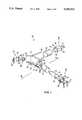
- FIG. 1is an exploded view of the invention
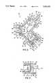
- FIG. 2is a cross sectional top view of the invention taken along a horizontal centerline;
- FIG. 3is a cross sectional side view of the first transmitter end taken along the line 3--3 of FIG. 2;
- FIG. 4is a circuit diagram showing the transmitter and receiver circuits.
- FIG. 5is a circuit diagram showing the signal processing circuits.
- the gas-sensor deviceis indicated by the numeral 10 and is used to detect the concentration of oxygen, based upon analysis of ultrasonic sound waves traveling through a binary gas sample.
- the sound-wave delay through the binary gasmay be measured for calculation of the oxygen concentration level within a binary gas sample.
- An accurate determination of the concentration of oxygenrequires analysis of various environmental conditions including, but not limited to, length of the chamber, temperature, pressure, and humidity.
- the gas-sensor device 10is preferably used for analysis of a binary gas composed of a mixture of oxygen and nitrogen. As such, all components of the gas-sensor device 10 are preferably selected to be unaffected by, and/or non-reactive to, oxygen and nitrogen gas.
- the gas-sensor device 10includes the following elements: an L-shaped housing 12 having a first transmitter end 14, a second gas outflow end 16, a junction open receiver end 18, and a gas inlet port 20; a transmitter assembly 22 having a transmitter/transducer 24, and a diode 26; a gas outflow cap assembly 28 having a sonic baffle 30, and a gas outlet port 32; a receiver assembly 34 having a receiver/transducer 36; and a sound buffer 38.
- the L-shaped housing 12is preferably of one-piece construction and is formed of injection-molded polycarbonate plastic material. Alternatively, the L-shaped housing 12 may be formed by bonding two pieces of polycarbonate material together proximal to the junction open receiver end 18.
- the L-shaped housing 12is preferably formed to withstand internal gas pressure of twenty, plus or minus two pounds per square inch.
- the gas-sensor device 10is preferably exposed to five pounds per square inch of pressure during normal operational conditions. In the event of a failure of an external pressure regulator, pressures in the range of twelve to fifteen pounds per square inch may be exposed to the L-shaped housing 12.
- the L-shaped housing 12is preferably tubular, having a circular cross-sectional dimension.
- the L-shaped housing 12preferably has an exterior diameter dimension approximating one inch and an interior diameter dimension approximating three-quarters of an inch.
- a transducer chamberexists between the first open transmitter end 14 and the junction open receiver end 18.
- the transducer chamberis preferably linear, having a length dimension approximating one inch.
- a defined length for the transducer chamberoptimizes the performance of the gas-sensor device 10, specifically with respect to the pulse width of the generated ultrasonic waves, over temperature and concentration conditions, within the L-shaped housing 12.
- a linear transducer chambermaximizes performance of the gas-sensor device 10 during use of a pulsed sound wave.
- L-shaped housing 12maximizes performance of the gas-sensor device 10 during use of sound waves which are continuously excited within the transducer chamber.
- An advantage of use of an L-shaped housing 12, during continuous sound-wave operation,is the reduction in the complication of electrical circuitry. Specifically, the delay and sample-and-hold circuitry are not required in continuous sound-wave operation, but are required in pulsed sound-wave operational conditions.
- the L-shaped housing 12includes a first open transmitter end 14, a second open gas outflow end 16, a junction open receiver end 18, and a gas inlet port 20.
- the first open transmitter end 14 and the second open gas outflow end 16are preferably positioned at opposite ends of the L-shaped housing 12.
- the junction open receiver end 18is preferably positioned equal distances from each of the first open transmitter end 14 and the second open gas outflow end 16.
- the gas inlet port 20is preferably positioned equal distances between the first open transmitter end 14 and the junction open receiver end 18, passing through an exterior wall of the L-shaped housing 12.
- the first open transmitter end 14generally includes a first grooved surface 40, a second grooved surface 42, and a first interior surface 44.
- Second grooved surface 42is preferably engaged to the transmitter assembly 22.
- the first grooved surface 40is preferably positioned proximal, and encircles, the interior of the first open transmitter end 14.
- the first grooved surface 40preferably has a diameter dimension slightly smaller than the exterior diameter dimension of the L-shaped housing 12.
- the second grooved surface 42is preferably positioned proximal to the first grooved surface 40 encircling the interior of the L-shaped housing 12.
- the second grooved surface 42is preferably of smaller diameter than the first grooved surface 40, facilitating engagement to the transmitter assembly 22.
- the first interior surface 44is preferably positioned proximal to the second grooved surface 42 and extends the length of the transducer chamber within the interior of the L-shaped housing 12.
- the first interior surface 44forms the interior diameter dimension of the L-shaped housing 12, which approximates three-quarters inch.
- a plurality of engagement slots 46traverse the first grooved surface 40.
- the engagement slots 46are preferably adapted for coupling receipt of lead wires 47 which are electrically connected to electrical contacts of the transmitter/transducer 24.
- the first open transmitter end 14is adapted for receiving engagement of the transmitter assembly 22 within the interior of the L-shaped housing 12.
- the ledge created between the second grooved surface 42 and the first interior surface 44preferably functions as a stop limiting the penetrating engagement of the transmitter assembly 22 within the first open transmitter end 14. The exact positioning of the transmitter assembly 22 is thereby accomplished by the precise formation of the width of the second grooved surface 42.
- the open gas outflow end 16generally includes a first channel surface 48 and a second interior surface 50.
- the first channel surface 48is preferably engaged to the gas outflow end cap assembly 28.
- the first channel surface 48is preferably positioned proximal to, and encircles, the interior edge of the second open gas outflow end 16.
- the first channel surface 48preferably has a diameter dimension slightly smaller than the exterior diameter dimension of the L-shaped housing 12.
- the second interior surface 50is preferably positioned proximal to the first channel surface 48 and extends the length of the L-shaped housing 12, between the second open gas outflow end 16 and the junction open receiver end 18.
- the second interior surface 50forms the interior dimension of the L-shaped housing 12, which approximates three-quarters of an inch.
- a portion of the circumference of the first channel surface 48is preferably in flush engagement to the exterior surface of the gas outflow end cap assembly 28.
- the open gas outflow end 16is thereby adapted for receiving engagement of the gas outflow end cap assembly 28 within the interior of the L-shaped housing 12.
- the ledge created between the first channel surface 48, and the second interior surface 50,preferably functions as a stop limiting the penetrating engagement of the gas outflow end cap assembly 28 within the second open gas outflow end 16.
- the exact positioning of the gas outflow end cap assembly 28is thereby accomplished by the precise formation of the width of the first channel surface 48.
- the first channel surface 48preferably has the same diameter dimension as the first grooved surface 40, and the second interior surface 50 preferably has the same diameter dimension as the first interior surface 44.
- the junction open receiver end 18generally includes a first ridge surface 52 and a second ridge surface 54.
- the second ridge surface 54is preferably engaged to the receiver assembly 34.
- the first ridge surface 52is preferably positioned proximal to, and encircles, the interior of the junction open receiver end 18.
- the first ridge surface 52preferably has a diameter dimension slightly smaller than the exterior diameter dimension of the L-shaped housing 12.
- the second ridge surface 54is preferably positioned proximal to the first ridge surface 52 encircling the interior of the L-shaped housing 12.
- the second ridge surface 54is preferably of smaller diameter dimension than the first ridge surface 52, facilitating engagement to the receiver assembly 34.
- a plurality of engagement slots 46atraverse the first ridge surface 52.
- the engagement slots 46aare preferably adapted for coupling receipt of lead wires 49 which are electrically connected to the electrical contacts of the receiver/transponder 36.
- the entire circumference of the second ridge surface 54is in flush engagement to the exterior surface of the receiver assembly 34.
- the junction open receiver end 18is thereby adapted for receiving engagement of the receiver assembly 34 within the interior of the L-shaped housing 12.
- the exact positioning of the receiver assembly 34is thereby accomplished by the precise formation of the width of the second ridge surface 54.
- the first ridge surface 52preferably has the same diameter dimension as the first grooved surface 40 and the first channel surface 48; the second ridge surface 54 preferably has the same diameter dimension as the second grooved surface 42.
- the diameter of the second ridge surface 54has a smaller dimension than either the first interior surface 44 or the second interior surface 50.
- a stop ledge 56is thereby established at the position of the interface between the second ridge surface 54 and the first interior surface 44 and the second interior surface 50. The stop ledge 56 functions to limit the penetration of the receiver assembly 34 into the junction open receiver end 18.
- the gas inlet port 20is preferably positioned equidistant between the first open transmitter end 14 and the junction open receiver end 18.
- the gas inlet port 20includes a central aperture 58 and is preferably molded through the L-shaped housing 12.
- the central aperture 58preferably passes through an exterior wall of the L-shaped housing 12 defining the inlet for the flow of binary gas to be analyzed by the gas-sensor device 10. It should be noted that the position of the gas inlet port 20 may be suitably relocated to any preferred position with respect to the L-shaped housing 12, so long as the binary gas inlet is positioned proximal to the transducer chamber.
- the gas inlet port 20may be of any preferred length, width, and diameter dimensions at the discretion of an individual provided that the essential functions, features, and attributes described herein are not sacrificed.
- the gas inlet port 20is preferably formed of the same plastic material as the L-shaped housing 12 and is thereby able to withstand, without fracture or fail, gas pressure within the range of twenty pounds per square inch.
- a gas inlet port 20may be attached to the L-shaped housing 12 by threaded penetrating and receiving means as may be available. If a threaded inlet port is to be used, a sealing means may additionally be required to insure the sealed integrity between the gas inlet port 20 and the L-shaped housing 12.
- the gas inlet port 20may include ribs at the preference of an individual to facilitate engagement to a hose connected in air-flow relation to a binary gas source.
- the transmitter assembly 22includes a transmitter/transducer 24 mounted to a transmitter base 59, an electrical ground connection 60, and an electrical input connection 62; a diode 26 having an anode 64 and a cathode 66; and a transmitter end cap 68 having a plurality of apertures 70 (FIGS. 1 and 2).
- the transmitter end cap 68is preferably formed of the same polycarbonate or plastic material as the L-shaped housing 12.
- the transmitter end cap 68is preferably cylindrical in shape having a diameter adapted for flush and sealed engagement to the second grooved surface 42 of the first open transmitter end 14.
- the width dimension of the transmitter end cap 68is preferably equal to the width dimension of the second grooved surface 42.
- the transmitter end cap 68includes a plurality of apertures 70 which are adapted for alignment to the engagement slots 46 of the first grooved surface 40.
- the apertures 70provide for the convenient electrical connection of lead wires 47 to the electrical ground connection 60, electrical input connection 62, anode 64, and cathode 66.
- the purpose of the transmitter end cap 68is to seal the first open transmitter end 14, and centrally position the transmitter/transducer 24 within the interior of the L-shaped housing 12. Another purpose of the transmitter end cap 68 is to position the transmitter/transducer 24 at a fixed location with respect to the transducer chamber, such that a defined calculated distance dimension exists between transmitter/transducer 24 and the receiver/transponder 36. A known distance between the transmitter/transducer 24 and the receiver/transponder 36 enables an individual to calculate the time delay for the passing of ultrasonic waves through a binary gas, thereby enabling an individual to determine the concentration of a gas within a binary gas mixture.
- the transmitter/transducer 24is preferably mounted to a transmitter base 59 which is cylindrical in shape and is formed of the same plastic material as the transmitter end cap 68.
- the electrical ground connection 60 and the electrical input connection 62preferably pass through the transmitter base 59 for the ultimate electrical connection to the lead wires 47.
- the electrical ground connection 60 and the electrical input connection 62then pass through the central pair of apertures 70 of the transmitter end cap 68.
- the transmitter base 59is preferably affixed to the transmitter end cap 68 and is positioned for flush engagement thereto.
- the lead wires 47are preferably positioned for electrical connection to the electrical ground connection 60 and the electrical input connection 62, and the anode and cathode connections.
- the diode 26preferably extends from the transmitter end cap 68 toward the receiver/transponder 36 a distance approximating 0.6 inches.
- the diode 26includes connector wires which pass through the exterior pair of apertures 70, of the transmitter end cap 68, for connection to the lead wires 47.
- Diode 26may be a Type IN4148, and the purpose of the diode 26 is to continuously monitor the temperature of the binary gas within the transducer chamber. The temperature of the binary gas, in addition to the distance between the transmitter and receiver elements, is required in order to calculate the concentration of a gas within the gas detection device 10.
- the diode 26is angularly offset with respect to the transducer chamber and the path existing between the transmitter/transducer 24 and the receiver/transponder 36.
- the diode 26preferably does not interfere with the ultrasonic waves generated by the transmitter/transducer 26, to an extent requiring inclusion of a factor or term in a time delay equation during the calculation of the concentration of a gas within a binary gas mixture.
- the diode 26preferably does not cause standing waves within the transducer chamber thereby interfering with the signals to be detected by the receiver/transponder 36 during use of the gas-sensor device 10.
- the diode 26is preferably located at a substantially central position approximately equidistant between the transmitter/transducer 24 and the receiver/transponder 36.
- the diode 26is also preferably positioned proximal to, but not in contact with, the sound buffer 74 within the interior of the L-shaped housing 12.
- the transmitter end cap 68, electrical ground connection 60, electrical input connection 62, anode 64, and cathode 66are preferably sealed within the first open transmitter end 14 by potting compound.
- the apertures 70are preferably restricted or plugged following engagement to the electrical ground connection 60, electrical input connection 62, anode 64, and cathode 66, in order to facilitate sealing of the first open transmitter end 14.
- a seal of the transmitter end cap 68should occur where the seal is able to withstand pressure of twenty pounds per square inch plus or minus two pounds per square inch.
- the potting compoundpreferably is filled to establish a flush surface with respect to the edge of the L-shaped housing 12, thereby covering and enclosing the lead wires 47 with a minimum thickness of potting compound approximating 100 mil.
- the purpose of the transmitter/transducer 24is to generate ultrasonic sound waves for detection by the receiver/transponder 36.
- the reduction of standing waves, and/or standing wave signals caused by the reflection/refraction of the ultrasonic sound waves within the L-shaped housing 12,is of primary importance.
- the optimization for reduction of the signal-to-noise ratio and improvement of the accuracy and performance of the gas saving device 10is highly desirable.
- the transmitter/transducer 24is preferably able to function and produce a stable output of ultrasonic sound waves over a temperature range of 10° to 45° C.
- a stable output of ultrasonic sound wavesis required in order to provide an operating frequency for the transmitter/transducer 24, and for receipt by the receiver/transponder 36, such that the sound-wave delay measurement must fall within one period of the oscillator frequency.
- the preferred operational frequency for the transmitter/transducer 24is 40 khz.
- the transmitter/transducer 24is preferably selected to provide sound delays within the transducer chamber such that the pulse width determined by the electronic circuits remains within a twenty-five micro second window of the oscillator. Preferably the pulse width for the ultrasonic signals continues within one to twenty-four micro seconds over the full temperature and concentration ranges for the gas detection device 10.
- the pulse width for the ultrasonic signalsmay be controlled by selecting the correct polarity of the transmitter/transducer 24 and receiver/transponder 36 elements. It should be noted that the total sound delay through the transducer chamber is greater than the actual pulse width measured.
- the transmitter/transducer 24is preferably selected for its temperature stability and its operating frequency.
- the temperature stabilityis required for the transmitter/transducer 24 characteristics to remain stable and resist change over the operating temperature range of the device.
- the operating frequencyis preferably selected for the availability of the gas-sensor device 10 and the pulse width range at the indicated frequency.
- the preferred distance between the transmitter/transducer 24 and the receiver/transponder 36approximates 0.850 ⁇ 0.005 inches.
- the transmitter/transducer 24 in the preferred embodimentis a Panasonic P/N EFROSB 4 ⁇ K65 unit.
- the diode 26is preferably a IN4148 unit as available from National SemiConductor, Inc.
- the gas outflow end cap assembly 28includes a sonic baffle 30 and a gas outlet port 32.
- the gas outlet port 32is preferably formed of the same polycarbonate or plastic material as the L-shaped housing 12 and the transmitter end cap 68.
- the gas outflow end cap assembly 28in general includes a circular base 76 having a centrally-positioned aperture 78 therethrough, and a cylindrically-shaped barbed extension 80 extending outward from the circular base 76.
- the cylindrical-shaped barb extension 80is preferably aligned to the centrally-positioned aperture 78.
- the diameter dimension for the centrally-positioned aperture 78 and the cylindrically-shaped barbed extension 80is preferably the same as the diameter dimension for central aperture 58 of the gas inlet port 20.
- the diameter dimension for the circular base 76is preferably equal to the diameter dimension for the first channel surface 48.
- the circular base 76is preferably adapted for flush and airtight engagement to the first channel surface 48.
- the purpose of the circular base 76is to seal the second open gas outflow end 16 defining a gas flow course from the gas inlet port 20 to the gas outlet port 32. Another purpose of the circular base 76 is to fixedly position the sonic baffle 30 within the second open outflow end 16.
- the sonic baffle 30preferably includes a collar 82 which is affixed to the circular base 76 proximal to its circumference.
- the sonic baffle 30is preferably conical in shape, and includes a plurality of baffle slots 84 which extend longitudinally through the conical portion.
- the sonic baffle 30extends outwardly from the circular base 76 where the tip of the conical portion is positioned centrally within the interior of the second open gas outflow end 16 facing the receiver/transponder 36.
- the collar 82is preferably positioned in flush contact with the ridge established between the first channel surface 48 and the second interior surface 50, which functions as a stop, limiting the penetrating engagement of the gas outflow end cap assembly 28 within the second open outflow end 16. It should be noted that the sonic baffle 30 completely traverses the interior of the L-shaped housing 12 proximal to the second open gas outflow end 16.
- the sonic baffle 30is preferably formed of injected molded plastic and functions to dampen and reduce reflected and/or refracted ultrasonic sound waves within the L-shaped housing 12. Sonic baffle 30 functions to significantly reduce the standing waves within the L-shaped housing 12. The minimization of standing waves significantly enhances the performance of the gas-sensor device 10 by improving the signal-to-noise ratio and elevating of the performance of the receiver/transponder 36.
- the baffle slots 84function to permit passage of air into the rear interior of the sonic baffle 30.
- a binary gas flow courseis established within the interior of the L-shaped housing 12, between the gas inlet port 20 and the gas outlet port 32.
- a binary gas sourceis attached to the gas inlet port 20.
- the binary gas sourcepreferably permits access of gas within the gas-sensor device 10 at a rate of zero to five liters per minute.
- the binary gasinitially enters the transducer chamber proximal to the transmitter/transducer 24.
- the binary gasthen flows toward the receiver/transponder 36 as indicated by arrow 5.
- the binary gasthen follows the L-shaped housing 12 toward the sonic baffle 30 and the gas outlet port 32 as indicated by arrow 6.
- the binary gasthen exits the L-shaped housing 12, via the gas outlet port 32, as indicated by arrow 7.
- the interior of the L-shaped housing 12is preferably sealed for limiting access of the binary gas air-flow course between the gas inlet port 20 and the gas outlet port 32. A desired level of pressure within the gas-sensor device 10 is thereby sustained.
- the second open gas outflow end 16is preferably sealed by the application and drying of potting compound which forms a good seal.
- the seal of the gas outflow end cap assembly 28 to the second open gas outflow end 16is preferably of sufficient strength to withstand internal pressure approximating twenty pounds per square inch. Following curing of the potting compound, for a period approximating 24 hours, the seal of the second open gas outflow end 16 is preferable to withstand a pressure of twenty pounds per square inch, plus or minus two pounds per square inch.
- a volume of potting compoundis preferably filled into the second open gas outflow end 16 in order to establish a flush surface with respect to the edge of the L-shaped housing 12, having a minimum thickness approximating 100 mil.
- the receiver assembly 34includes a receiver/transponder 36 mounted to a receiver base 85, an electrical connection 86, an electrical connection 88, and a receiver end cap 90.
- the receiver end cap 90is preferably formed of the same plastic material as the L-shaped housing 12.
- the receiver end cap 90is preferably cylindrical in shape having a diameter dimension adapted for flush and sealed engagement to the second ridge surface 54 of the junction open receiver end 18.
- the width dimension of the receiver end cap 90is preferably equal to the width dimension of the second ridge surface 54.
- the receiver end cap 90includes a pair of apertures 92 which are adapted for alignment to the engagement slots 46a of the first ridge surface 52.
- the apertures 92provide for the convenient electrical connection of lead wires 49 to the electrical connection 86 and the electrical connection 88.
- receiver end cap 90The purpose of the receiver end cap 90 is to seal the junction open receiver end 18 and centrally position the receiver/transponder 36 within the interior of the L-shaped housing 12. Another purpose of the receiver end cap 90 is to position the receiver/transponder 36 at a fixed location within the transducer chamber, such that a defined calculated distance dimension exists between the transmitter/transducer 24 and the receiver/transponder 36.
- the receiver/transponder 36is preferably mounted to a receiver base 85 which is cylindrical in shape and is formed of the same plastic material as the receiver end cap 90.
- the electrical connection 86 and the electrical connection 88preferably pass through the receiver base 85 for ultimate electrical connection to the lead wires 49.
- the electrical connection 86 and the electrical connection 88pass through the respective pair of apertures 92 of the receiver end cap 90.
- the receiver base 85is preferably affixed to the receiver end cap 90 and is positioned for flush engagement thereto.
- the lead wires 49are positioned for electrical connection to the electrical connection 86 and the electrical connection 88.
- the receiver end cap 90, the electrical connection 86, and the electrical connection 88are preferably sealed within the junction open receiver end 18 by potting compound. It should be noted that the pair of apertures 92 of the receiver end cap 90 are preferably restricted or plugged following engagement to the electrical ground connection 86 and electrical output connection 88 in order to facilitate sealing of the junction open receiver end 18. Following the curing of the potting compound, for a period approximating twenty-four hours, the sealing of the receiving end cap 90, within the junction open receiver end 18, should occur where the seal is able to withstand a pressure of twenty pounds per square inch, plus or minus two pounds per square inch.
- a volume of potting compoundpreferably is into the junction open receiver end 18 to establish a flush surface with respect to the edge of the L-shaped housing 12, thereby covering and enclosing the lead wires 49 with a minimum thickness of potting compound approximating 100 mil.
- An oscillator/driver circuit 100generates a continuous sequence of pulses at a frequency determined by crystal oscillator 101.
- Crystal oscillator 101is preferably selected to provide a 40 khz signal.
- the oscillator frequency signalis shaped and amplified by drivers 102, and applied to transmitter 24 via input connection 62.
- Input connection 60is connected to ground potential.
- Transmitter 24forms a part of the sensor and signal condition circuits 104. Transmitter 24 generates an acoustical signal which is received by receiver 36, and converted into an electrical signal applied across electrical connections 86 and 88.
- a comparator 105which generates an output signal whenever the input signal exceeds a predetermined value.
- the output from comparator 105is applied via inverter circuits to a flip-flop circuit 108.
- Flip-flop circuit 106receives the initial oscillator pulse signal via line 107, indicative of the time at which the initial signal was generated.
- the signal on line 107causes flip-flop circuit 106 to become set, thereby generating a signal on line 110; the signal from flip-flop circuit 108 causes flip-flop 106 to reset, thereby removing the signal on line 110. Therefore, the signal on line 10 is present during the time interval beginning with a generation of the oscillator signal and ending with the receipt of the acoustical signal by receiver 36.
- Temperature diode 26generates a voltage level on output line 112, which voltage is representative of the temperature within housing 12.
- the temperature signal on line 112is coupled into temperature compensation circuit 114.
- This signalis compared against a reference value and is applied to a summing circuit 122 via line 115.
- the sensor circuit output signal on line 110is applied to a pulse width/voltage converter circuit 124, which integrates the pulse signal input to develop an output voltage on line 120 which is the function of the time of the input pulse.
- the signals on lines 115 and 120are applied to summer circuit 122, and the sum of these signals is applied via line 125 to the calibration and output circuit 130.
- the calibration and output circuit 130provides potentiometer adjustments for calibrating the ambient temperature value and the maximum voltage swing for the output signal. This circuit is adjusted so as to provide an analog output voltage on line 140 which is directly representative of the oxygen content of the gas flowing through gas-sensor device 10.
- the circuit components utilized in the diagrams of FIGS. 4 and 5are commercially available components, which may be obtained from a number of manufacturers under well-known type designations.
- the amplifiers Aare preferably Type LM358 or Type LM324 circuits;
- the inverters Iare preferably Type 4049 circuits;
- the flip-flop circuitsare preferably Type 4013 circuits, available from various manufacturers such as Motorola.
- the purpose of the receiver/transponder 36is to detect ultrasonic sound waves as produced by the transmitter/transducer 22.
- the receiver/transponder 36is preferably positioned parallel to the junction open receiver end 18, which angularly offsets the position of the receiver/transponder 36 with respect to the transmitter/transducer 24 by an angle of approximately 45°.
- the angularly offset positioning of the receiver/transponder 36 with respect to the transmitter/transducer 24reduces reflection of ultrasonic sound waves back toward the transmitter/transducer 24, thereby significantly reducing standing waves. It is expected that ultrasonic waves reflecting off the receiver/transponder 36 emanate toward the sonic baffle 30, as opposed to return to the transmitter/transducer 24.
- the receiver/transponder 36is centrally positioned within the interior of the L-shaped housing 12 proximal to the junction open receiver end 18 and is unobstructively aligned to the transmitter/transducer 24.
- the receiver/transponder 36operates on the frequency of 40 khz for receipt of signals as generated by the transmitter/transducer 24.
- the spacing between the transmitter/transducer 24 and the receiver/transponder 36is selected to provide sound delays in the transducer chamber such that the pulse width determined by the electronic circuitry remains within a twenty-five micro second window of the oscillator.
- the pulse width for the signalpreferably continues within one to twenty-four micro seconds over the full temperature and concentration operational ranges for the gas-sensor device 10.
- the pulse widthcan be controlled also by selecting the correct polarity of the transmitter/transducer 24 or receiver/transponder 36 elements. It should be noted that the total sound delay through the transducer chamber is greater than the actual pulse width measured.
- the receiver/transponder 36is preferably selected for its temperature stability within the noted operating frequency. Temperature stability is required so that the receiver/transponder 36 characteristics do not change over the operating temperature ranges for the device.
- the receiver/transponder 36is preferably located 0.85 inches from the transmitter/transducer 24. The mounting of the receiver/transponder 36 at a 45° degree angle from the center line of the transmitter/transducer 24 reduces the reflection effects of ultrasonic waves back into emanating sounds waves from the transmitter/transducer 24. It is also required that the receiver/transponder 36 include a reasonably constant output amplitude over the full concentration ranges of gas to be detected. If the receiver/transponder 36 amplitude is not constant, the rise time of the output signal will have an effect on the measured output.
- the spacing of the receiver/transponder 36 from a transmitter/transducer 24must be selected so that the pulse width value falls within twenty-five micro seconds. Therefore, this spacing should approximate 0.850 ⁇ 0.005 inches.
- the actual sound delay between the transmitter/transducer 24 and the receiver/transponder 36is between 50 to 75 micro seconds. During the generation of a continuous ultrasonic sound wave through the transducer chamber, 50 micro seconds are subtracted off the total time by starting the pulse width measurement with the oscillator signal. During implementation of a pulsed ultrasonic sound waves through the transducer chamber, 50 micro seconds are subtracted by delaying the start pulse by an appropriate amount. Therefore, the spacing would be identical for both excitation methods.
- the mounting of the receiver/transponder 36 the end of a straight chamberoperates efficiently for pulsed mode operations. Standing sound waves are minimized due to the dying out of the ultrasonic sound waves between each burst of sound pulses.
- the use of a straight tubecauses the ultrasonic sound waves to bounce off the receiver/transponder 36 back into the oncoming ultrasonic waves, which extenuates the incoming signals at different rates over the concentration range. This phenomena causes the output error to be larger than desired. Therefore, the L-shaped housing 12 is preferred when a continuous ultrasonic sound wave is generated.
- the ultrasonic sound wavestravel down the L-shaped housing 12 where they are reflected off the receiver/transponder 36 down into the second open gas outflow end 16, which includes the sonic baffle 30.
- the sonic baffle 30functions to dampen the signal as the ultrasonic sound waves contact the sonic baffle 30 and the sound buffer means 74.
- the receiver/transponder 36is preferably a Panasonic EFRRSB 4 ⁇ K65 unit.
- the sound buffer 74is preferably positioned proximal to the interior walls of the L-shaped housing 12 within the first open transmitter end 14 and the second open gas outflow end 16.
- the sound buffer 74preferably reduces reflective/refracted ultrasonic sound waves within the L-shaped housing 12.
- the sound buffer 74is preferably formed of a fabric material, and in the preferred embodiment is comprised of wool felt.
- any preferred materialmay be used as the sound buffer 74, including but not limited to the use of cotton, paper, synthetic fibers, and/or foam sound insulating material, provided that the essential functions, features, and attributes described herein are not sacrificed.
- the sound buffer 74completely covers the interior of the L-shaped housing 12 including the transducer chamber, without gaps especially along mating seams.
- the edges of the sound buffer 74are preferably cut to flushly cover all interior surfaces of the L-shaped housing without overlap of material.
- the sound buffer 74preferably functions to reduce the reflection/refraction of ultrasonic sound waves as generated by the transmitter/transducer 24.
- the reduction of reflected/refracted ultrasonic sound wavesminimizes standing waves, which in turn minimizes background noise, thereby improving the signal-to-noise ratio and performance of the gas-sensor device 10. A more accurate determination of the concentration of oxygen within a binary gas sample is therefore available.
- the primary function of the sound buffer 74is to attenuate the reflection of ultrasonic sound waves off of the internal sidewalls of the L-shaped housing 12.
- the sound buffer 74is preferably sufficiently dense to keep ultrasonic sound waves from traversing the fabric material and reflecting back through the material into the interior of the L-shaped housing 12.
- the material selected for the sound buffer 74may, however, not be so dense as to cause that ultrasonic sound waves to reflect off the sound buffer 74, thereby escalating the volume and amount of standing waves and background noise within the interior of the L-shaped housing 12. It should be noted that many acoustical foams do not include a sufficient density to attenuate ultrasonic sound waves before reflecting off of the sidewalls of the interior of the L-shaped housing 12.
- the sound buffer 74preferably reduces the turbulence between the transmitter/transducer 24 and the receiver/transponder 36.
- the sound buffer, in the form of wool felt, 74may be obtained from the manufacture of Armstrong/Kover Kwick Inc., part no. KK5016 which has 1/16 inch thickness dimension and a density/weight of one pound per square inch.
- the temperature of the binary gasis required to be measured via the diode 26 in order to compensate the output reading for an accurate determination of the concentration of oxygen within the gas sample.
- the ultrasonic sound waves generated within the L-shaped housing 12travel through the binary gas at a faster rate due to the molecules of the gas moving at an increased rate due to the higher temperature.
- the object of the gas-sensor device 10is to calculate the concentration of oxygen within the gas sample.
- the humidity of the binary gas sampleeffects the ultrasonic sound-wave delay between the transmitter/transducer 24 and the receiver/transponder 36. If the gas-sensor device 10 is to be used as a portion of an oxygen concentrator apparatus, then the humidity parameter factor may be ignored.
- the pressure level of the binary gas samplemay effect the performance of the gas-sensor device 10.
- the pressureis typically regulated at a constant five pounds per square inch.
- the pressure parametermay also be ignored.
- the ultrasonic sound-wave equation generated by a gas-sensor deviceis nonlinear over distance; however, at the distance which the ultrasonic sound waves travel within the transducer chamber the ultrasonic sound-wave equation may be considered as linear for calculation purposes. If continuous ultrasonic sound-wave operation is required for the gas-sensor device 10, an L-shaped housing 12 should be used to keep the ultrasonic sound waves from being reflected back into the oncoming ultrasonic sound waves as generated by the transmitter/transducer 24. If the gas-sensor device 10 is to be used in determinations of oxygen concentration below forty percent, the pulsed method for generation of ultrasonic sound waves is preferred above a continuous ultrasonic sound-wave generation device.
- the gas inlet port 20 and gas outlet port 32are located such that the binary gas sample must cross the path of the ultrasonic sound waves generated within the transducer chamber.
- the gas inlet port 20is located proximal to and in front of the transmitter/transducer 24.
- the gas outlet port 32is positioned in the gas outflow end cap assembly 28 which is at the opposite end of the L-shaped housing 12 from the transmitter/transducer 24.
- the gas flow pathis generally shown by arrows 5, 6 and 7 in FIG. 2.
Landscapes
- Physics & Mathematics (AREA)
- Biochemistry (AREA)
- Health & Medical Sciences (AREA)
- Life Sciences & Earth Sciences (AREA)
- Chemical & Material Sciences (AREA)
- Analytical Chemistry (AREA)
- General Health & Medical Sciences (AREA)
- General Physics & Mathematics (AREA)
- Immunology (AREA)
- Pathology (AREA)
- Acoustics & Sound (AREA)
- Engineering & Computer Science (AREA)
- Computer Networks & Wireless Communication (AREA)
- Investigating Or Analyzing Materials By The Use Of Ultrasonic Waves (AREA)
Abstract
Description
This invention relates generally to an ultrasonic gas measuring device for detecting and determining the concentration of oxygen within a binary oxygen gas mixture. The concentration of oxygen within a binary gas mixture is then used in therapeutic medicinal applications. The invention incorporates a means for providing a more efficient and precise determination of the concentration of oxygen within a binary gas mixture, such as an oxygen/nitrogen mixture.
In the past, the analysis of simpler gas mixtures normally required the use of measurement techniques which involved difficult calibration procedures, replenishment of reagent chemicals, and/or other awkward, costly or time-consuming procedures.
Prior art devices have been developed to continuously monitor the ratio of two known gases within a gas mixture. A typical example of a binary gas composition to be measured would include oxygen/nitrogen mixtures used in the therapeutic administration of oxygen from oxygen concentrators in home health care environments. Additionally, respirators, ventilators, and air/oxygen blenders are commonly used in hospitals requiring known ranges of oxygen concentration. Gas concentration detection devices are also used in medical applications involving the application of anesthesia to individuals. In the medical field, many patients require supplemental oxygen. The two most common forms for the supply of oxygen include bottled oxygen compressed and confined within a canister, and oxygen concentrators which convert room air into oxygen. Many states require oxygen concentrators to include oxygen monitors installed to verify the concentration levels for the supply of therapeutic oxygen. Oxygen concentrator suppliers may therefore use oxygen monitors to verify correct operation, and reduce the need for maintenance of oxygen detection devices.
Prior art oxygen measurement devices are extremely sensitive to changes in temperature and are generally poorly temperature compensated. In addition, these devices are extremely sensitive to barometric pressure or humidity changes. Acoustical techniques have been used for gas analysis for measurement of the concentration of a particular gas within a binary gas mixture. The use of acoustical techniques creates severe technical problems with respect to the analysis of gases, due to the mechanical, electronic, and thermal problems associated with standing waves, temperature variations, and barometric pressure or humidity variances. The temperature of the gas must be measured and used to compensate for an accurate output reading. As the temperature increases, the sound waves within the transducer chamber travel at a faster rate due to the increased speed of the molecules of gas moving within the chamber.
Continuous wave systems have been considered appealing, due to the ability of such systems to use a resonant transmitter and receiver element which affords an adequate signal-to-noise ratio, acceptable sensitivity, and simplicity of design for a gas concentration measurement device. However, the continuous-wave approach is not free from problems, particularly with respect to standing waves within the closed transducer chamber. In a continuous-wave system, the receiver accepts acoustic energy from the transmitter within a transducer chamber and generates a signal, with a phase shift, which is affected by the mean molecular weight and temperature of the gas to be detected. The acoustical waves within the transducer chamber reflect from various surfaces, thus setting up standing waves that frustrate repeatability measurements. In addition, upon excitation of the transmitted energy, the receiver retransmits a signal at its anti-resonant frequency, in a complex fashion, back toward the transmitter. As a result, a beat frequency is encountered which yields unpredictable effects in response to temperature variations. The primary problem of gas-sensing devices, as known, is the standing waves which are encountered within the transducer chamber yielding unacceptable high signal-to-noise ratios and/or signal frequency errors.
The disclosed invention provides a more precise analysis of the concentration of a gas or gases within a gaseous mixture, primarily through the elimination of reflected standing waves within a transducer chamber. The invention thereby furnishes a more consistent and accurate analysis of the specific concentration of any one of the gases being detected, particularly oxygen, than can be achieved through the usage of the individual or combined prior art teachings.
An example of the prior art teachings include the U.S. Pat. No. 5,060,506 to Douglas and the U.S. Pat. No. 5,060,514 issued to Aylsworth. Both patents generally disclose ultrasonic gas measuring devices for the measurement of gas mixtures involving a transducer chamber having a design which does not minimize signal-to-noise ratios resulting from standing waves.
In general, the invention relates to an oxygen sensor which measures the concentration of oxygen based upon ultrasonic sound waves traveling through a binary gas. The measured sound wave delay through the gases determines the concentration level for oxygen within the transducer chamber. The invention includes an L-shaped housing where a transmitter/transducer is attached to one end of the housing and the receiver/transponder is positioned at the junction between the two substantially straight portions of the L-shaped housing. A straight transducer chamber is thereby provided, while simultaneously providing a housing design which minimizes reflected standing waves for detection by the receiver/transponder. Background noise is thereby significantly reduced while enhancing the signal-to-noise ratio for the gas detection device. The invention includes a sonic baffle positioned at the opposite end of the L-shaped housing from the transmitter/transducer which minimizes standing waves thereby improving the performance of the gas detection device. The invention also includes a sound buffer means affixed to the interior of the L-shaped housing which further reduces the existence and reflection of standing waves for detection by the receiver/transponder. Temperature is monitored within the transducer chamber by an angularly offset sensor which provides the necessary environmental conditions for the accurate determination of a gas concentration within the gas detection device.
It is an object of the present invention to provide a new and improved gas-sensor device of relatively simple and inexpensive design, construction, and operation which is accurate, safe, durable, and reliable, and which fulfills the intended purpose of measuring the concentration of oxygen within a binary gas mixture without fear of inaccurate readings, injury to persons, and/or damage to property.
It is another object of the present invention to reduce standing ultrasonic waves within a transducer chamber thereby improving the accuracy of the measured concentration of oxygen within the gas-sensor device.
It is still another object of the present invention to improve the signal-to-noise ratio within a transducer chamber thereby improving the accuracy of the measured concentration of oxygen within the gas-sensor device.
A feature of the present invention includes an L-shaped housing having a transmitter/transducer at one end, a sonic baffle at the opposite end of the L-shaped housing, and a receiver/transponder positioned approximately equal distances between the transmitter/transducer and the sonic baffle, where the L-shaped housing reduces standing waves for detection by the receiver/transponder.
Another feature of the present invention includes an angularly offset sensor for measuring the temperature of the gas within the transducer chamber for the provision of accurate environmental conditions for calculation of the concentration of oxygen within the gas-sensing device.
Still another feature of the present invention includes a conical-shaped sonic baffle having a plurality of longitudinal slots for reduction of standing waves within the L-shaped housing, thereby minimizing errors in the calculation of oxygen concentration within the transducer chamber.
Still another feature of the present invention includes a sound buffer means, formed of a sound-absorbent material, which is positioned proximal to the interior walls of the L-shaped housing minimizing standing waves within the transducer chamber.
FIG. 1 is an exploded view of the invention;
FIG. 2 is a cross sectional top view of the invention taken along a horizontal centerline;
FIG. 3 is a cross sectional side view of the first transmitter end taken along theline 3--3 of FIG. 2;
FIG. 4 is a circuit diagram showing the transmitter and receiver circuits; and
FIG. 5 is a circuit diagram showing the signal processing circuits.
One form of the gas-sensor device is illustrated and described herein. In general, the gas-sensor device is indicated by thenumeral 10 and is used to detect the concentration of oxygen, based upon analysis of ultrasonic sound waves traveling through a binary gas sample. The sound-wave delay through the binary gas may be measured for calculation of the oxygen concentration level within a binary gas sample. An accurate determination of the concentration of oxygen requires analysis of various environmental conditions including, but not limited to, length of the chamber, temperature, pressure, and humidity. The gas-sensor device 10 is preferably used for analysis of a binary gas composed of a mixture of oxygen and nitrogen. As such, all components of the gas-sensor device 10 are preferably selected to be unaffected by, and/or non-reactive to, oxygen and nitrogen gas.
In general, the gas-sensor device 10 includes the following elements: an L-shaped housing 12 having afirst transmitter end 14, a secondgas outflow end 16, a junctionopen receiver end 18, and agas inlet port 20; atransmitter assembly 22 having a transmitter/transducer 24, and adiode 26; a gasoutflow cap assembly 28 having asonic baffle 30, and agas outlet port 32; areceiver assembly 34 having a receiver/transducer 36; and asound buffer 38.
The L-shaped housing 12 is preferably of one-piece construction and is formed of injection-molded polycarbonate plastic material. Alternatively, the L-shaped housing 12 may be formed by bonding two pieces of polycarbonate material together proximal to the junctionopen receiver end 18. The L-shaped housing 12 is preferably formed to withstand internal gas pressure of twenty, plus or minus two pounds per square inch. The gas-sensor device 10 is preferably exposed to five pounds per square inch of pressure during normal operational conditions. In the event of a failure of an external pressure regulator, pressures in the range of twelve to fifteen pounds per square inch may be exposed to the L-shapedhousing 12. The L-shapedhousing 12 is preferably tubular, having a circular cross-sectional dimension. The L-shapedhousing 12 preferably has an exterior diameter dimension approximating one inch and an interior diameter dimension approximating three-quarters of an inch. Within the interior of the L-shapedhousing 12, a transducer chamber exists between the firstopen transmitter end 14 and the junctionopen receiver end 18. The transducer chamber is preferably linear, having a length dimension approximating one inch. A defined length for the transducer chamber optimizes the performance of the gas-sensor device 10, specifically with respect to the pulse width of the generated ultrasonic waves, over temperature and concentration conditions, within the L-shapedhousing 12.
Generally, a linear transducer chamber maximizes performance of the gas-sensor device 10 during use of a pulsed sound wave. L-shapedhousing 12 maximizes performance of the gas-sensor device 10 during use of sound waves which are continuously excited within the transducer chamber. An advantage of use of an L-shapedhousing 12, during continuous sound-wave operation, is the reduction in the complication of electrical circuitry. Specifically, the delay and sample-and-hold circuitry are not required in continuous sound-wave operation, but are required in pulsed sound-wave operational conditions.
The L-shapedhousing 12 includes a firstopen transmitter end 14, a second opengas outflow end 16, a junctionopen receiver end 18, and agas inlet port 20. The firstopen transmitter end 14 and the second opengas outflow end 16 are preferably positioned at opposite ends of the L-shapedhousing 12. The junctionopen receiver end 18 is preferably positioned equal distances from each of the firstopen transmitter end 14 and the second opengas outflow end 16. Thegas inlet port 20 is preferably positioned equal distances between the firstopen transmitter end 14 and the junctionopen receiver end 18, passing through an exterior wall of the L-shapedhousing 12.
The firstopen transmitter end 14 generally includes a firstgrooved surface 40, a secondgrooved surface 42, and a firstinterior surface 44. Secondgrooved surface 42 is preferably engaged to thetransmitter assembly 22. The firstgrooved surface 40 is preferably positioned proximal, and encircles, the interior of the firstopen transmitter end 14. The firstgrooved surface 40 preferably has a diameter dimension slightly smaller than the exterior diameter dimension of the L-shapedhousing 12. The secondgrooved surface 42 is preferably positioned proximal to the firstgrooved surface 40 encircling the interior of the L-shapedhousing 12. The secondgrooved surface 42 is preferably of smaller diameter than the firstgrooved surface 40, facilitating engagement to thetransmitter assembly 22. The firstinterior surface 44 is preferably positioned proximal to the secondgrooved surface 42 and extends the length of the transducer chamber within the interior of the L-shapedhousing 12. The firstinterior surface 44 forms the interior diameter dimension of the L-shapedhousing 12, which approximates three-quarters inch.
A plurality ofengagement slots 46 traverse the firstgrooved surface 40. Theengagement slots 46 are preferably adapted for coupling receipt oflead wires 47 which are electrically connected to electrical contacts of the transmitter/transducer 24.
The firstopen transmitter end 14 is adapted for receiving engagement of thetransmitter assembly 22 within the interior of the L-shapedhousing 12. The ledge created between the secondgrooved surface 42 and the firstinterior surface 44 preferably functions as a stop limiting the penetrating engagement of thetransmitter assembly 22 within the firstopen transmitter end 14. The exact positioning of thetransmitter assembly 22 is thereby accomplished by the precise formation of the width of the secondgrooved surface 42.
Referring to FIG. 2, the opengas outflow end 16 generally includes afirst channel surface 48 and a secondinterior surface 50. Thefirst channel surface 48 is preferably engaged to the gas outflowend cap assembly 28. Thefirst channel surface 48 is preferably positioned proximal to, and encircles, the interior edge of the second opengas outflow end 16. Thefirst channel surface 48 preferably has a diameter dimension slightly smaller than the exterior diameter dimension of the L-shapedhousing 12. The secondinterior surface 50 is preferably positioned proximal to thefirst channel surface 48 and extends the length of the L-shapedhousing 12, between the second opengas outflow end 16 and the junctionopen receiver end 18. The secondinterior surface 50 forms the interior dimension of the L-shapedhousing 12, which approximates three-quarters of an inch.
A portion of the circumference of thefirst channel surface 48 is preferably in flush engagement to the exterior surface of the gas outflowend cap assembly 28. The opengas outflow end 16 is thereby adapted for receiving engagement of the gas outflowend cap assembly 28 within the interior of the L-shapedhousing 12. The ledge created between thefirst channel surface 48, and the secondinterior surface 50, preferably functions as a stop limiting the penetrating engagement of the gas outflowend cap assembly 28 within the second opengas outflow end 16. The exact positioning of the gas outflowend cap assembly 28 is thereby accomplished by the precise formation of the width of thefirst channel surface 48. Thefirst channel surface 48 preferably has the same diameter dimension as the firstgrooved surface 40, and the secondinterior surface 50 preferably has the same diameter dimension as the firstinterior surface 44.
The junctionopen receiver end 18 generally includes afirst ridge surface 52 and asecond ridge surface 54. Thesecond ridge surface 54 is preferably engaged to thereceiver assembly 34. Thefirst ridge surface 52 is preferably positioned proximal to, and encircles, the interior of the junctionopen receiver end 18. Thefirst ridge surface 52 preferably has a diameter dimension slightly smaller than the exterior diameter dimension of the L-shapedhousing 12. Thesecond ridge surface 54 is preferably positioned proximal to thefirst ridge surface 52 encircling the interior of the L-shapedhousing 12. Thesecond ridge surface 54 is preferably of smaller diameter dimension than thefirst ridge surface 52, facilitating engagement to thereceiver assembly 34.
A plurality ofengagement slots 46a traverse thefirst ridge surface 52. Theengagement slots 46a are preferably adapted for coupling receipt oflead wires 49 which are electrically connected to the electrical contacts of the receiver/transponder 36. Preferably, the entire circumference of thesecond ridge surface 54 is in flush engagement to the exterior surface of thereceiver assembly 34. The junctionopen receiver end 18 is thereby adapted for receiving engagement of thereceiver assembly 34 within the interior of the L-shapedhousing 12. The exact positioning of thereceiver assembly 34 is thereby accomplished by the precise formation of the width of thesecond ridge surface 54. Thefirst ridge surface 52 preferably has the same diameter dimension as the firstgrooved surface 40 and thefirst channel surface 48; thesecond ridge surface 54 preferably has the same diameter dimension as the secondgrooved surface 42.
It should be noted that the diameter of thesecond ridge surface 54 has a smaller dimension than either the firstinterior surface 44 or the secondinterior surface 50. Astop ledge 56 is thereby established at the position of the interface between thesecond ridge surface 54 and the firstinterior surface 44 and the secondinterior surface 50. Thestop ledge 56 functions to limit the penetration of thereceiver assembly 34 into the junctionopen receiver end 18.
Thegas inlet port 20 is preferably positioned equidistant between the firstopen transmitter end 14 and the junctionopen receiver end 18. Thegas inlet port 20 includes acentral aperture 58 and is preferably molded through the L-shapedhousing 12. Thecentral aperture 58 preferably passes through an exterior wall of the L-shapedhousing 12 defining the inlet for the flow of binary gas to be analyzed by the gas-sensor device 10. It should be noted that the position of thegas inlet port 20 may be suitably relocated to any preferred position with respect to the L-shapedhousing 12, so long as the binary gas inlet is positioned proximal to the transducer chamber. Thegas inlet port 20 may be of any preferred length, width, and diameter dimensions at the discretion of an individual provided that the essential functions, features, and attributes described herein are not sacrificed.
Thegas inlet port 20 is preferably formed of the same plastic material as the L-shapedhousing 12 and is thereby able to withstand, without fracture or fail, gas pressure within the range of twenty pounds per square inch. Alternatively, agas inlet port 20 may be attached to the L-shapedhousing 12 by threaded penetrating and receiving means as may be available. If a threaded inlet port is to be used, a sealing means may additionally be required to insure the sealed integrity between thegas inlet port 20 and the L-shapedhousing 12.
Thegas inlet port 20 may include ribs at the preference of an individual to facilitate engagement to a hose connected in air-flow relation to a binary gas source.
In general, thetransmitter assembly 22 includes a transmitter/transducer 24 mounted to atransmitter base 59, anelectrical ground connection 60, and anelectrical input connection 62; adiode 26 having ananode 64 and acathode 66; and atransmitter end cap 68 having a plurality of apertures 70 (FIGS. 1 and 2).
Thetransmitter end cap 68 is preferably formed of the same polycarbonate or plastic material as the L-shapedhousing 12. Thetransmitter end cap 68 is preferably cylindrical in shape having a diameter adapted for flush and sealed engagement to the secondgrooved surface 42 of the firstopen transmitter end 14. The width dimension of thetransmitter end cap 68 is preferably equal to the width dimension of the secondgrooved surface 42. Thetransmitter end cap 68 includes a plurality ofapertures 70 which are adapted for alignment to theengagement slots 46 of the firstgrooved surface 40. Theapertures 70 provide for the convenient electrical connection oflead wires 47 to theelectrical ground connection 60,electrical input connection 62,anode 64, andcathode 66.
The purpose of thetransmitter end cap 68 is to seal the firstopen transmitter end 14, and centrally position the transmitter/transducer 24 within the interior of the L-shapedhousing 12. Another purpose of thetransmitter end cap 68 is to position the transmitter/transducer 24 at a fixed location with respect to the transducer chamber, such that a defined calculated distance dimension exists between transmitter/transducer 24 and the receiver/transponder 36. A known distance between the transmitter/transducer 24 and the receiver/transponder 36 enables an individual to calculate the time delay for the passing of ultrasonic waves through a binary gas, thereby enabling an individual to determine the concentration of a gas within a binary gas mixture.
The transmitter/transducer 24 is preferably mounted to atransmitter base 59 which is cylindrical in shape and is formed of the same plastic material as thetransmitter end cap 68. Theelectrical ground connection 60 and theelectrical input connection 62 preferably pass through thetransmitter base 59 for the ultimate electrical connection to thelead wires 47. Theelectrical ground connection 60 and theelectrical input connection 62 then pass through the central pair ofapertures 70 of thetransmitter end cap 68. It should be noted that thetransmitter base 59 is preferably affixed to thetransmitter end cap 68 and is positioned for flush engagement thereto. It should also be noted that thelead wires 47 are preferably positioned for electrical connection to theelectrical ground connection 60 and theelectrical input connection 62, and the anode and cathode connections.
Thediode 26 preferably extends from thetransmitter end cap 68 toward the receiver/transponder 36 a distance approximating 0.6 inches. Thediode 26 includes connector wires which pass through the exterior pair ofapertures 70, of thetransmitter end cap 68, for connection to thelead wires 47.Diode 26 may be a Type IN4148, and the purpose of thediode 26 is to continuously monitor the temperature of the binary gas within the transducer chamber. The temperature of the binary gas, in addition to the distance between the transmitter and receiver elements, is required in order to calculate the concentration of a gas within thegas detection device 10.
Thediode 26 is angularly offset with respect to the transducer chamber and the path existing between the transmitter/transducer 24 and the receiver/transponder 36. Thediode 26 preferably does not interfere with the ultrasonic waves generated by the transmitter/transducer 26, to an extent requiring inclusion of a factor or term in a time delay equation during the calculation of the concentration of a gas within a binary gas mixture. Thediode 26 preferably does not cause standing waves within the transducer chamber thereby interfering with the signals to be detected by the receiver/transponder 36 during use of the gas-sensor device 10. Thediode 26 is preferably located at a substantially central position approximately equidistant between the transmitter/transducer 24 and the receiver/transponder 36. Thediode 26 is also preferably positioned proximal to, but not in contact with, thesound buffer 74 within the interior of the L-shapedhousing 12.
Thetransmitter end cap 68,electrical ground connection 60,electrical input connection 62,anode 64, andcathode 66 are preferably sealed within the firstopen transmitter end 14 by potting compound. It should be noted that theapertures 70 are preferably restricted or plugged following engagement to theelectrical ground connection 60,electrical input connection 62,anode 64, andcathode 66, in order to facilitate sealing of the firstopen transmitter end 14. Following the curing of the potting compound for a period approximating twenty-four hours, a seal of thetransmitter end cap 68 should occur where the seal is able to withstand pressure of twenty pounds per square inch plus or minus two pounds per square inch. The potting compound preferably is filled to establish a flush surface with respect to the edge of the L-shapedhousing 12, thereby covering and enclosing thelead wires 47 with a minimum thickness of potting compound approximating 100 mil.
The purpose of the transmitter/transducer 24 is to generate ultrasonic sound waves for detection by the receiver/transponder 36. The reduction of standing waves, and/or standing wave signals caused by the reflection/refraction of the ultrasonic sound waves within the L-shapedhousing 12, is of primary importance. The optimization for reduction of the signal-to-noise ratio and improvement of the accuracy and performance of thegas saving device 10 is highly desirable.
The transmitter/transducer 24 is preferably able to function and produce a stable output of ultrasonic sound waves over a temperature range of 10° to 45° C. A stable output of ultrasonic sound waves is required in order to provide an operating frequency for the transmitter/transducer 24, and for receipt by the receiver/transponder 36, such that the sound-wave delay measurement must fall within one period of the oscillator frequency. The preferred operational frequency for the transmitter/transducer 24 is 40 khz.
The transmitter/transducer 24 is preferably selected to provide sound delays within the transducer chamber such that the pulse width determined by the electronic circuits remains within a twenty-five micro second window of the oscillator. Preferably the pulse width for the ultrasonic signals continues within one to twenty-four micro seconds over the full temperature and concentration ranges for thegas detection device 10. The pulse width for the ultrasonic signals may be controlled by selecting the correct polarity of the transmitter/transducer 24 and receiver/transponder 36 elements. It should be noted that the total sound delay through the transducer chamber is greater than the actual pulse width measured. The following formula is used for determination of the pulse width for the ultrasonic signals; the "pulse width" equals the "total delay" through the transducer chamber minus the number of oscillation cycles multiplied by the oscillation period. The transmitter/transducer 24 is preferably selected for its temperature stability and its operating frequency. The temperature stability is required for the transmitter/transducer 24 characteristics to remain stable and resist change over the operating temperature range of the device. The operating frequency is preferably selected for the availability of the gas-sensor device 10 and the pulse width range at the indicated frequency.
The preferred distance between the transmitter/transducer 24 and the receiver/transponder 36 approximates 0.850±0.005 inches. The transmitter/transducer 24 in the preferred embodiment is a Panasonic P/N EFROSB 4φK65 unit. In the preferred embodiment, thediode 26 is preferably a IN4148 unit as available from National SemiConductor, Inc.
In general, the gas outflowend cap assembly 28 includes asonic baffle 30 and agas outlet port 32. Thegas outlet port 32 is preferably formed of the same polycarbonate or plastic material as the L-shapedhousing 12 and thetransmitter end cap 68.
The gas outflowend cap assembly 28 in general includes acircular base 76 having a centrally-positionedaperture 78 therethrough, and a cylindrically-shapedbarbed extension 80 extending outward from thecircular base 76. The cylindrical-shapedbarb extension 80 is preferably aligned to the centrally-positionedaperture 78. The diameter dimension for the centrally-positionedaperture 78 and the cylindrically-shapedbarbed extension 80, is preferably the same as the diameter dimension forcentral aperture 58 of thegas inlet port 20. The diameter dimension for thecircular base 76 is preferably equal to the diameter dimension for thefirst channel surface 48. Thecircular base 76 is preferably adapted for flush and airtight engagement to thefirst channel surface 48. The purpose of thecircular base 76 is to seal the second opengas outflow end 16 defining a gas flow course from thegas inlet port 20 to thegas outlet port 32. Another purpose of thecircular base 76 is to fixedly position thesonic baffle 30 within the secondopen outflow end 16.
Thesonic baffle 30 preferably includes acollar 82 which is affixed to thecircular base 76 proximal to its circumference. Thesonic baffle 30 is preferably conical in shape, and includes a plurality ofbaffle slots 84 which extend longitudinally through the conical portion. Thesonic baffle 30 extends outwardly from thecircular base 76 where the tip of the conical portion is positioned centrally within the interior of the second opengas outflow end 16 facing the receiver/transponder 36. Thecollar 82 is preferably positioned in flush contact with the ridge established between thefirst channel surface 48 and the secondinterior surface 50, which functions as a stop, limiting the penetrating engagement of the gas outflowend cap assembly 28 within the secondopen outflow end 16. It should be noted that thesonic baffle 30 completely traverses the interior of the L-shapedhousing 12 proximal to the second opengas outflow end 16.
Thesonic baffle 30 is preferably formed of injected molded plastic and functions to dampen and reduce reflected and/or refracted ultrasonic sound waves within the L-shapedhousing 12. Sonic baffle 30 functions to significantly reduce the standing waves within the L-shapedhousing 12. The minimization of standing waves significantly enhances the performance of the gas-sensor device 10 by improving the signal-to-noise ratio and elevating of the performance of the receiver/transponder 36. Thebaffle slots 84 function to permit passage of air into the rear interior of thesonic baffle 30.
It should be noted that a binary gas flow course is established within the interior of the L-shapedhousing 12, between thegas inlet port 20 and thegas outlet port 32. Initially, a binary gas source is attached to thegas inlet port 20. The binary gas source preferably permits access of gas within the gas-sensor device 10 at a rate of zero to five liters per minute. The binary gas initially enters the transducer chamber proximal to the transmitter/transducer 24. The binary gas then flows toward the receiver/transponder 36 as indicated by arrow 5. The binary gas then follows the L-shapedhousing 12 toward thesonic baffle 30 and thegas outlet port 32 as indicated byarrow 6. The binary gas then exits the L-shapedhousing 12, via thegas outlet port 32, as indicated byarrow 7. The interior of the L-shapedhousing 12 is preferably sealed for limiting access of the binary gas air-flow course between thegas inlet port 20 and thegas outlet port 32. A desired level of pressure within the gas-sensor device 10 is thereby sustained.
The second opengas outflow end 16 is preferably sealed by the application and drying of potting compound which forms a good seal. The seal of the gas outflowend cap assembly 28 to the second opengas outflow end 16 is preferably of sufficient strength to withstand internal pressure approximating twenty pounds per square inch. Following curing of the potting compound, for a period approximating 24 hours, the seal of the second opengas outflow end 16 is preferable to withstand a pressure of twenty pounds per square inch, plus or minus two pounds per square inch. A volume of potting compound is preferably filled into the second opengas outflow end 16 in order to establish a flush surface with respect to the edge of the L-shapedhousing 12, having a minimum thickness approximating 100 mil.
In general, thereceiver assembly 34 includes a receiver/transponder 36 mounted to areceiver base 85, anelectrical connection 86, anelectrical connection 88, and areceiver end cap 90. Thereceiver end cap 90 is preferably formed of the same plastic material as the L-shapedhousing 12. Thereceiver end cap 90 is preferably cylindrical in shape having a diameter dimension adapted for flush and sealed engagement to thesecond ridge surface 54 of the junctionopen receiver end 18. The width dimension of thereceiver end cap 90 is preferably equal to the width dimension of thesecond ridge surface 54. Thereceiver end cap 90 includes a pair ofapertures 92 which are adapted for alignment to theengagement slots 46a of thefirst ridge surface 52. Theapertures 92 provide for the convenient electrical connection oflead wires 49 to theelectrical connection 86 and theelectrical connection 88.
The purpose of thereceiver end cap 90 is to seal the junctionopen receiver end 18 and centrally position the receiver/transponder 36 within the interior of the L-shapedhousing 12. Another purpose of thereceiver end cap 90 is to position the receiver/transponder 36 at a fixed location within the transducer chamber, such that a defined calculated distance dimension exists between the transmitter/transducer 24 and the receiver/transponder 36.
The receiver/transponder 36 is preferably mounted to areceiver base 85 which is cylindrical in shape and is formed of the same plastic material as thereceiver end cap 90. Theelectrical connection 86 and theelectrical connection 88 preferably pass through thereceiver base 85 for ultimate electrical connection to thelead wires 49. Theelectrical connection 86 and theelectrical connection 88 pass through the respective pair ofapertures 92 of thereceiver end cap 90. It should also be noted that thereceiver base 85 is preferably affixed to thereceiver end cap 90 and is positioned for flush engagement thereto. It should also be noted that thelead wires 49 are positioned for electrical connection to theelectrical connection 86 and theelectrical connection 88.
Thereceiver end cap 90, theelectrical connection 86, and theelectrical connection 88 are preferably sealed within the junctionopen receiver end 18 by potting compound. It should be noted that the pair ofapertures 92 of thereceiver end cap 90 are preferably restricted or plugged following engagement to theelectrical ground connection 86 andelectrical output connection 88 in order to facilitate sealing of the junctionopen receiver end 18. Following the curing of the potting compound, for a period approximating twenty-four hours, the sealing of the receivingend cap 90, within the junctionopen receiver end 18, should occur where the seal is able to withstand a pressure of twenty pounds per square inch, plus or minus two pounds per square inch. A volume of potting compound preferably is into the junctionopen receiver end 18 to establish a flush surface with respect to the edge of the L-shapedhousing 12, thereby covering and enclosing thelead wires 49 with a minimum thickness of potting compound approximating 100 mil.
Referring next to FIG. 4, a circuit diagram illustrating the transmitter and receiver circuits is illustrated. An oscillator/driver circuit 100 generates a continuous sequence of pulses at a frequency determined bycrystal oscillator 101.Crystal oscillator 101 is preferably selected to provide a 40 khz signal. The oscillator frequency signal is shaped and amplified bydrivers 102, and applied totransmitter 24 viainput connection 62.Input connection 60 is connected to ground potential.Transmitter 24 forms a part of the sensor andsignal condition circuits 104.Transmitter 24 generates an acoustical signal which is received byreceiver 36, and converted into an electrical signal applied acrosselectrical connections comparator 105 which generates an output signal whenever the input signal exceeds a predetermined value. The output fromcomparator 105 is applied via inverter circuits to a flip-flop circuit 108. Flip-flop circuit 106 receives the initial oscillator pulse signal vialine 107, indicative of the time at which the initial signal was generated. The signal online 107 causes flip-flop circuit 106 to become set, thereby generating a signal online 110; the signal from flip-flop circuit 108 causes flip-flop 106 to reset, thereby removing the signal online 110. Therefore, the signal online 10 is present during the time interval beginning with a generation of the oscillator signal and ending with the receipt of the acoustical signal byreceiver 36.Temperature diode 26 generates a voltage level onoutput line 112, which voltage is representative of the temperature withinhousing 12.
Referring to FIG. 5, the temperature signal online 112 is coupled intotemperature compensation circuit 114. This signal is compared against a reference value and is applied to a summingcircuit 122 vialine 115. The sensor circuit output signal online 110 is applied to a pulse width/voltage converter circuit 124, which integrates the pulse signal input to develop an output voltage online 120 which is the function of the time of the input pulse. The signals onlines summer circuit 122, and the sum of these signals is applied vialine 125 to the calibration andoutput circuit 130. The calibration andoutput circuit 130 provides potentiometer adjustments for calibrating the ambient temperature value and the maximum voltage swing for the output signal. This circuit is adjusted so as to provide an analog output voltage online 140 which is directly representative of the oxygen content of the gas flowing through gas-sensor device 10.
The circuit components utilized in the diagrams of FIGS. 4 and 5 are commercially available components, which may be obtained from a number of manufacturers under well-known type designations. For example, the amplifiers A are preferably Type LM358 or Type LM324 circuits; the inverters I are preferably Type 4049 circuits; the flip-flop circuits are preferably Type 4013 circuits, available from various manufacturers such as Motorola.
The purpose of the receiver/transponder 36 is to detect ultrasonic sound waves as produced by the transmitter/transducer 22. The receiver/transponder 36 is preferably positioned parallel to the junctionopen receiver end 18, which angularly offsets the position of the receiver/transponder 36 with respect to the transmitter/transducer 24 by an angle of approximately 45°. The angularly offset positioning of the receiver/transponder 36 with respect to the transmitter/transducer 24 reduces reflection of ultrasonic sound waves back toward the transmitter/transducer 24, thereby significantly reducing standing waves. It is expected that ultrasonic waves reflecting off the receiver/transponder 36 emanate toward thesonic baffle 30, as opposed to return to the transmitter/transducer 24. It should be noted that the receiver/transponder 36 is centrally positioned within the interior of the L-shapedhousing 12 proximal to the junctionopen receiver end 18 and is unobstructively aligned to the transmitter/transducer 24.
The receiver/transponder 36 operates on the frequency of 40 khz for receipt of signals as generated by the transmitter/transducer 24. The spacing between the transmitter/transducer 24 and the receiver/transponder 36 is selected to provide sound delays in the transducer chamber such that the pulse width determined by the electronic circuitry remains within a twenty-five micro second window of the oscillator. The pulse width for the signal preferably continues within one to twenty-four micro seconds over the full temperature and concentration operational ranges for the gas-sensor device 10. The pulse width can be controlled also by selecting the correct polarity of the transmitter/transducer 24 or receiver/transponder 36 elements. It should be noted that the total sound delay through the transducer chamber is greater than the actual pulse width measured. The receiver/transponder 36 is preferably selected for its temperature stability within the noted operating frequency. Temperature stability is required so that the receiver/transponder 36 characteristics do not change over the operating temperature ranges for the device. The receiver/transponder 36 is preferably located 0.85 inches from the transmitter/transducer 24. The mounting of the receiver/transponder 36 at a 45° degree angle from the center line of the transmitter/transducer 24 reduces the reflection effects of ultrasonic waves back into emanating sounds waves from the transmitter/transducer 24. It is also required that the receiver/transponder 36 include a reasonably constant output amplitude over the full concentration ranges of gas to be detected. If the receiver/transponder 36 amplitude is not constant, the rise time of the output signal will have an effect on the measured output. The spacing of the receiver/transponder 36 from a transmitter/transducer 24 must be selected so that the pulse width value falls within twenty-five micro seconds. Therefore, this spacing should approximate 0.850±0.005 inches. The actual sound delay between the transmitter/transducer 24 and the receiver/transponder 36 is between 50 to 75 micro seconds. During the generation of a continuous ultrasonic sound wave through the transducer chamber, 50 micro seconds are subtracted off the total time by starting the pulse width measurement with the oscillator signal. During implementation of a pulsed ultrasonic sound waves through the transducer chamber, 50 micro seconds are subtracted by delaying the start pulse by an appropriate amount. Therefore, the spacing would be identical for both excitation methods.
The mounting of the receiver/transponder 36 the end of a straight chamber operates efficiently for pulsed mode operations. Standing sound waves are minimized due to the dying out of the ultrasonic sound waves between each burst of sound pulses. During use of a continuous ultrasonic sound-wave signal, the use of a straight tube causes the ultrasonic sound waves to bounce off the receiver/transponder 36 back into the oncoming ultrasonic waves, which extenuates the incoming signals at different rates over the concentration range. This phenomena causes the output error to be larger than desired. Therefore, the L-shapedhousing 12 is preferred when a continuous ultrasonic sound wave is generated. In this embodiment, the ultrasonic sound waves travel down the L-shapedhousing 12 where they are reflected off the receiver/transponder 36 down into the second opengas outflow end 16, which includes thesonic baffle 30. Thesonic baffle 30 functions to dampen the signal as the ultrasonic sound waves contact thesonic baffle 30 and the sound buffer means 74. The receiver/transponder 36 is preferably a Panasonic EFRRSB 4φK65 unit.
Thesound buffer 74 is preferably positioned proximal to the interior walls of the L-shapedhousing 12 within the firstopen transmitter end 14 and the second opengas outflow end 16. Thesound buffer 74 preferably reduces reflective/refracted ultrasonic sound waves within the L-shapedhousing 12. Thesound buffer 74 is preferably formed of a fabric material, and in the preferred embodiment is comprised of wool felt. Alternatively, any preferred material may be used as thesound buffer 74, including but not limited to the use of cotton, paper, synthetic fibers, and/or foam sound insulating material, provided that the essential functions, features, and attributes described herein are not sacrificed. It should be noted that thesound buffer 74 completely covers the interior of the L-shapedhousing 12 including the transducer chamber, without gaps especially along mating seams. The edges of thesound buffer 74 are preferably cut to flushly cover all interior surfaces of the L-shaped housing without overlap of material.
Thesound buffer 74 preferably functions to reduce the reflection/refraction of ultrasonic sound waves as generated by the transmitter/transducer 24. The reduction of reflected/refracted ultrasonic sound waves minimizes standing waves, which in turn minimizes background noise, thereby improving the signal-to-noise ratio and performance of the gas-sensor device 10. A more accurate determination of the concentration of oxygen within a binary gas sample is therefore available.
The primary function of thesound buffer 74 is to attenuate the reflection of ultrasonic sound waves off of the internal sidewalls of the L-shapedhousing 12. Thesound buffer 74 is preferably sufficiently dense to keep ultrasonic sound waves from traversing the fabric material and reflecting back through the material into the interior of the L-shapedhousing 12. The material selected for thesound buffer 74 may, however, not be so dense as to cause that ultrasonic sound waves to reflect off thesound buffer 74, thereby escalating the volume and amount of standing waves and background noise within the interior of the L-shapedhousing 12. It should be noted that many acoustical foams do not include a sufficient density to attenuate ultrasonic sound waves before reflecting off of the sidewalls of the interior of the L-shapedhousing 12. These acoustical foams attenuate sound waves below 5 khz. In addition to the reduction of standing waves within the interior of the L-shapedhousing 12, thesound buffer 74 preferably reduces the turbulence between the transmitter/transducer 24 and the receiver/transponder 36.
The sound buffer, in the form of wool felt, 74 may be obtained from the manufacture of Armstrong/Kover Kwick Inc., part no. KK5016 which has 1/16 inch thickness dimension and a density/weight of one pound per square inch.
During operation of the gas-sensor device 10, the temperature of the binary gas is required to be measured via thediode 26 in order to compensate the output reading for an accurate determination of the concentration of oxygen within the gas sample. As the temperature of the binary gas increases, the ultrasonic sound waves generated within the L-shapedhousing 12 travel through the binary gas at a faster rate due to the molecules of the gas moving at an increased rate due to the higher temperature. The object of the gas-sensor device 10 is to calculate the concentration of oxygen within the gas sample. The humidity of the binary gas sample effects the ultrasonic sound-wave delay between the transmitter/transducer 24 and the receiver/transponder 36. If the gas-sensor device 10 is to be used as a portion of an oxygen concentrator apparatus, then the humidity parameter factor may be ignored. In addition, the pressure level of the binary gas sample may effect the performance of the gas-sensor device 10. Again, if an oxygen concentrator device is used, the pressure is typically regulated at a constant five pounds per square inch. Thus, the pressure parameter may also be ignored. Generally, the ultrasonic sound-wave equation generated by a gas-sensor device is nonlinear over distance; however, at the distance which the ultrasonic sound waves travel within the transducer chamber the ultrasonic sound-wave equation may be considered as linear for calculation purposes. If continuous ultrasonic sound-wave operation is required for the gas-sensor device 10, an L-shapedhousing 12 should be used to keep the ultrasonic sound waves from being reflected back into the oncoming ultrasonic sound waves as generated by the transmitter/transducer 24. If the gas-sensor device 10 is to be used in determinations of oxygen concentration below forty percent, the pulsed method for generation of ultrasonic sound waves is preferred above a continuous ultrasonic sound-wave generation device.
It should be noted that during use of the gas-sensor device 10, thegas inlet port 20 andgas outlet port 32 are located such that the binary gas sample must cross the path of the ultrasonic sound waves generated within the transducer chamber. Thegas inlet port 20 is located proximal to and in front of the transmitter/transducer 24. Thegas outlet port 32 is positioned in the gas outflowend cap assembly 28 which is at the opposite end of the L-shapedhousing 12 from the transmitter/transducer 24. The gas flow path is generally shown byarrows
The present invention may be embodied in other specific forms without departing from the spirit or essential attributes thereof; therefore, the illustrated embodiment should be considered in all respects as illustrative and not restrictive, reference being made to the appended claims rather than to the foregoing description to indicate the scope of the invention.
Claims (46)
1. A gas-sensor device for detection of the presence and concentration of a gas, said gas-sensor device comprising:
(a) an L-shaped housing having a first transmitter end, a second gas outflow end, a junction receiver end, and a gas inlet port through said L-shaped housing proximal to said first transmitter end, said gas inlet port permitting flow-through access of said gas to be detected;
(b) a transmitter assembly having a transmitter/transducer and a temperature sensor positioned in said first transmitter end, said transmitter/transducer having means for generating sound waves for passing through said gas within said L-shaped housing;
(c) a gas outflow end cap assembly having a sonic baffle and a gas outlet port positioned in said second gas outflow end, said sonic baffle having means for reducing reflection of said sound waves within the said L-shaped housing;
(d) a receiver assembly having a receiver/transponder for receipt of said sound waves positioned in said junction receiver end; and
(e) a sound buffer means for reduction of reflected sound waves, said sound buffer means engaged to said L-shaped housing, said first transmitter end, said second gas outflow end, and to said receiver assembly.
2. The gas-sensor device according to claim 1, wherein said L-shaped housing is tubular in shape.
3. The gas-sensor device according to claim 1, wherein said L-shaped housing has a first grooved surface proximal to said first transmitter end.
4. The gas-sensor device according to claim 3, wherein said L-shaped housing has a second grooved surface of smaller diameter than said first grooved surface, said second grooved surface being positioned proximal to said first grooved surface within said first transmitter end of said L-shaped housing.
5. The gas-sensor device according to claim 4, wherein said first transmitter end has a first interior surface of smaller diameter than said second grooved surface, said first interior surface being positioned proximal to said second grooved surface within said first transmitter end of said L-shaped housing.
6. The gas-sensor device according to claim 5, wherein said second gas outflow end has a first channel surface.
7. The gas-sensor device according to claim 6, wherein said second gas outflow end has a second interior surface of smaller diameter than said first channel surface, said second interior surface being positioned proximal to said first channel surface within said second gas outflow end of said L-shaped housing.
8. The gas-sensor device according to claim 1, wherein said junction receiver end has a stop ledge.
9. The gas-sensor device according to claim 1, wherein said transmitter assembly has a transmitter end cap, and input electrical connections affixed to said transmitter/transducer which pass through said transmitter end cap.
10. The gas-sensor device according to claim 9, wherein said temperature sensor further comprises a diode having anode and cathode electrical connections which pass through said transmitter end cap.
11. The gas-sensor device according to claim 1, wherein said temperature sensor is angularly offset with respect to said L-shaped housing and is positioned adjacent to said sound buffer means.
12. The gas-sensor device according to claim 1, wherein said temperature sensor is responsive to the temperature within said L-shaped housing.
13. The gas-sensor device according to claim 1, wherein said transmitter/transducer includes means for generating ultrasonic sound waves.
14. The gas-sensor device according to claim 1, wherein said sonic baffle is conical in shape extending within said L-shaped housing toward said junction receiver end.
15. The gas-sensor device according to claim 1, wherein said gas outlet port has a circular base having a centrally-positioned aperture therethrough and a cylindrical-shaped barbed extension aligned to said aperture.
16. A gas-sensor device according to claim 15, wherein said sonic baffle is affixed to, and extends inwardly from, said circular base of said gas outlet port.
17. The gas-sensor device according to claim 1, wherein said sonic baffle has a plurality of longitudinal slots.
18. The gas-sensor device according to claim 1, wherein said receiver assembly has a receiver end cap, and output electrical connections affixed to said receiver/transponder which traverse said receiver end cap.
19. The gas-sensor device according to claim 1, wherein said receiver assembly is angularly offset with respect to said L-shaped housing.
20. The gas-sensor device according to claim 19, wherein said receiver/transponder is angularly offset with respect to said L-shaped housing at an angle of 45°.
21. The gas-sensor device according to claim 1, wherein said transmitter/transducer and said receiver/transponder are aligned to one another within said L-shaped housing.
22. The gas-sensor device according to claim 1, wherein said sound buffer means comprises at least one felt insert.
23. The gas-sensor device according to claim 7, wherein said sound buffer means engages said first interior surface of said first transmitter end and said second interior surface of said second gas outflow end.
24. A gas-sensor device for detection of the presence and concentration of a gas, said gas-sensor device comprising:
(a) an L-shaped housing having a first transmitter end, a second gas outflow end, a junction receiver end, and a gas inlet port through said L-shaped housing proximal to said first transmitter end, said gas inlet port permitting flow-through access of said gas to be detected;
(b) a transmitter assembly having a transmitter/transducer and a temperature sensor positioned in said first transmitter end, said transmitter/transducer having means for generating sound waves for passing through said gas within said L-shaped housing;
(c) a gas outflow end cap assembly having a sonic baffle and a gas outlet port positioned in said second gas outflow end, said sonic baffle having means for reducing reflection of said sound waves within said L-shaped housing;
(d) a receiver assembly having a receiver/transponder means for receipt of said sound waves, positioned in said junction receiver end; and
(e) a fabric insert for reduction of reflected sound waves, said fabric insert being positioned within said L-shaped housing and being further engaged to said first transmitter end, said transmitter assembly, said second gas outflow end, said gas outflow end cap assembly, and to said receiver assembly.
25. The gas-sensor device according to claim 24, wherein said L-shaped housing is tubular in shape.
26. The gas-sensor device according to claim 24, wherein said L-shaped housing has a first grooved surface proximal to said first transmitter end.
27. The gas-sensor device according to claim 26, wherein said L-shaped housing has a second grooved surface of smaller diameter than said first grooved surface, said second grooved surface being positioned proximal to said first grooved surface within said first transmitter end of said L-shaped housing.
28. The gas-sensor device according to claim 27, wherein said first transmitter end has a first interior surface of smaller diameter than said second grooved surface, said first interior surface being positioned proximal to said second grooved surface within said first transmitter end of said L-shaped housing.
29. The gas-sensor device according to claim 28, wherein said second gas outflow end has a first channel surface.
30. The gas-sensor device according to claim 29, wherein said second gas outflow end has a second interior surface of smaller diameter than said first channel surface, said second interior surface being positioned proximal to said first channel surface within said second gas outflow end of said L-shaped housing.
31. The gas-sensor device according to claim 24, wherein said junction receiver end has a stop ledge.
32. The gas-sensor device according to claim 24, wherein said transmitter assembly has a transmitter end cap, and input electrical connections affixed to said transmitter/transducer which pass through said transmitter end cap.
33. The gas-sensor device according to claim 32, wherein said temperature sensor further comprises a diode having anode and cathode electrical connections which pass through said transmitter end cap.
34. The gas-sensor device according to claim 24, wherein said temperature sensor is angularly offset with respect to said L-shaped housing and is positioned adjacent to said sound buffer means.
35. The gas-sensor device according to claim 24, wherein said temperature sensor includes means for measuring the temperature within said L-shaped housing.
36. The gas-sensor device according to claim 24, wherein said transmitter/transducer includes means for generating ultrasonic sound waves.
37. The gas-sensor device according to claim 36, wherein said sonic baffle is conical in shape extending within said L-shaped housing toward said junction receiver end.
38. The gas-sensor device according to claim 24, wherein said gas outlet port has a circular base having a centrally-positioned aperture therethrough and a cylindrical-shaped barbed extension aligned to said aperture.
39. A gas-sensor device according to claim 38, wherein said sonic baffle is affixed to, and extends inwardly from, said circular base of said gas outlet port.
40. The gas-sensor device according to claim 24, wherein said sonic baffle has a plurality of longitudinal slots.
41. The gas-sensor device according to claim 24, wherein said receiver assembly has a receiver end cap, and output electrical connections affixed to said receiver/transponder which traverse said receiver end cap.
42. The gas-sensor device according to claim 24, wherein said receiver assembly is angularly offset with respect to said L-shaped housing.
43. The gas-sensor device according to claim 42, wherein said receiver/transponder is angularly offset with respect to said L-shaped housing at an angle of 45°.
44. The gas-sensor device according to claim 24, wherein said transmitter/transducer and said receiver/transponder are aligned to one another within said L-shaped housing.
45. The gas-sensor device according to claim 24, wherein said fabric insert is comprised of felt.
46. The gas-sensor device according to claim 30, wherein said fabric insert is engaged to said first interior surface of said first transmitter end and said second interior surface of said second gas outflow end.
Priority Applications (1)
| Application Number | Priority Date | Filing Date | Title |
|---|---|---|---|
| US08/147,326US5351522A (en) | 1993-11-02 | 1993-11-02 | Gas sensor |
Applications Claiming Priority (1)
| Application Number | Priority Date | Filing Date | Title |
|---|---|---|---|
| US08/147,326US5351522A (en) | 1993-11-02 | 1993-11-02 | Gas sensor |
Publications (1)
| Publication Number | Publication Date |
|---|---|
| US5351522Atrue US5351522A (en) | 1994-10-04 |
Family
ID=22521116
Family Applications (1)
| Application Number | Title | Priority Date | Filing Date |
|---|---|---|---|
| US08/147,326Expired - LifetimeUS5351522A (en) | 1993-11-02 | 1993-11-02 | Gas sensor |
Country Status (1)
| Country | Link |
|---|---|
| US (1) | US5351522A (en) |
Cited By (137)
| Publication number | Priority date | Publication date | Assignee | Title |
|---|---|---|---|---|
| WO1998007082A3 (en)* | 1996-08-15 | 1998-03-19 | Nellcor Puritan Bennett Inc | Apparatus and method for controlling output of an oxygen concentrator |
| US5768937A (en)* | 1996-11-13 | 1998-06-23 | Leybold Inficon, Inc. | Acoustic sensor for in-line continuous monitoring of gasses |
| US5792665A (en)* | 1996-05-29 | 1998-08-11 | Morrow, Iii; Donald W. | Oxygen sensing method and hand held analyzer therefore |
| WO1999054709A1 (en)* | 1998-04-17 | 1999-10-28 | Lorex Industries, Inc. | Apparatus and methods for performing acoustical measurements |
| US6202468B1 (en) | 1998-01-14 | 2001-03-20 | Life Measurement Instruments | Apparatus and method for the determination of the relative proportions of gases |
| US6279378B1 (en)* | 1999-10-27 | 2001-08-28 | The University Of Chicago | Ultrasonic gas analyzer and method to analyze trace gases |
| US6378372B1 (en) | 2000-05-17 | 2002-04-30 | Lawrence J. Karr | Acoustic resonance analysis of gas mixtures |
| US6460402B1 (en) | 1999-02-04 | 2002-10-08 | Bechtel Bwtx Idaho, Llc | Ultrasonic fluid quality sensor system |
| US6487916B1 (en) | 2000-02-02 | 2002-12-03 | Bechtel Bxwt Idaho, Llc | Ultrasonic flow metering system |
| US20030177813A1 (en)* | 2002-03-06 | 2003-09-25 | Ngk Spark Plug Co., Ltd. | Gas sensor |
| US20030217584A1 (en)* | 2002-03-06 | 2003-11-27 | Ngk Spark Plug Co., Ltd. | Gas sensor and gas concentration detecting device |
| US20040149285A1 (en)* | 2003-01-23 | 2004-08-05 | Maquet Critical Care Ab | Gas supply monitoring apparatus and method |
| US20040211244A1 (en)* | 2003-04-28 | 2004-10-28 | Maquet Critical Care Ab | Method and arrangement for acoustic determination of moisture content of a gas mixture |
| US6981947B2 (en) | 2002-01-22 | 2006-01-03 | University Of Florida Research Foundation, Inc. | Method and apparatus for monitoring respiratory gases during anesthesia |
| US7052468B2 (en) | 2001-05-24 | 2006-05-30 | University Of Florida Research Foundation, Inc. | Method and apparatus for detecting environmental smoke exposure |
| US7052854B2 (en) | 2001-05-23 | 2006-05-30 | University Of Florida Research Foundation, Inc. | Application of nanotechnology and sensor technologies for ex-vivo diagnostics |
| US7104963B2 (en) | 2002-01-22 | 2006-09-12 | University Of Florida Research Foundation, Inc. | Method and apparatus for monitoring intravenous (IV) drug concentration using exhaled breath |
| WO2006133738A1 (en) | 2005-06-17 | 2006-12-21 | Maquet Critical Care Ab | Reduction of pressure induced temperature influence on the speed of sound in a gas |
| US20090065007A1 (en)* | 2007-09-06 | 2009-03-12 | Wilkinson William R | Oxygen concentrator apparatus and method |
| USD606655S1 (en) | 2008-06-27 | 2009-12-22 | Inova Labs, Llc | Portable oxygen concentrator |
| US20100249549A1 (en)* | 2009-03-24 | 2010-09-30 | Nellcor Puritan Bennett Llc | Indicating The Accuracy Of A Physiological Parameter |
| US7820108B2 (en) | 1999-11-08 | 2010-10-26 | University Of Florida Research Foundation, Inc. | Marker detection method and apparatus to monitor drug compliance |
| EP2280275A2 (en) | 2005-06-17 | 2011-02-02 | Maquet Critical Care AB | Reduction of pressure induced temperature influence on the speed of sound in a gas |
| US7914460B2 (en) | 2006-08-15 | 2011-03-29 | University Of Florida Research Foundation, Inc. | Condensate glucose analyzer |
| US8211035B2 (en) | 2002-01-22 | 2012-07-03 | University Of Florida Research Foundation, Inc. | System and method for monitoring health using exhaled breath |
| US8400290B2 (en) | 2010-01-19 | 2013-03-19 | Covidien Lp | Nuisance alarm reduction method for therapeutic parameters |
| US8418692B2 (en) | 2009-12-04 | 2013-04-16 | Covidien Lp | Ventilation system with removable primary display |
| US8421465B2 (en) | 2009-12-02 | 2013-04-16 | Covidien Lp | Method and apparatus for indicating battery cell status on a battery pack assembly used during mechanical ventilation |
| US8418691B2 (en) | 2009-03-20 | 2013-04-16 | Covidien Lp | Leak-compensated pressure regulated volume control ventilation |
| US8424520B2 (en) | 2008-09-23 | 2013-04-23 | Covidien Lp | Safe standby mode for ventilator |
| US8425428B2 (en) | 2008-03-31 | 2013-04-23 | Covidien Lp | Nitric oxide measurements in patients using flowfeedback |
| US8424521B2 (en) | 2009-02-27 | 2013-04-23 | Covidien Lp | Leak-compensated respiratory mechanics estimation in medical ventilators |
| US8424523B2 (en) | 2009-12-03 | 2013-04-23 | Covidien Lp | Ventilator respiratory gas accumulator with purge valve |
| US8434480B2 (en) | 2008-03-31 | 2013-05-07 | Covidien Lp | Ventilator leak compensation |
| US8434479B2 (en) | 2009-02-27 | 2013-05-07 | Covidien Lp | Flow rate compensation for transient thermal response of hot-wire anemometers |
| US8439032B2 (en) | 2008-09-30 | 2013-05-14 | Covidien Lp | Wireless communications for a breathing assistance system |
| US8443294B2 (en) | 2009-12-18 | 2013-05-14 | Covidien Lp | Visual indication of alarms on a ventilator graphical user interface |
| US8439036B2 (en) | 2009-12-01 | 2013-05-14 | Covidien Lp | Exhalation valve assembly with integral flow sensor |
| US8439037B2 (en) | 2009-12-01 | 2013-05-14 | Covidien Lp | Exhalation valve assembly with integrated filter and flow sensor |
| US8448641B2 (en) | 2009-03-20 | 2013-05-28 | Covidien Lp | Leak-compensated proportional assist ventilation |
| US8453645B2 (en) | 2006-09-26 | 2013-06-04 | Covidien Lp | Three-dimensional waveform display for a breathing assistance system |
| US8453643B2 (en) | 2010-04-27 | 2013-06-04 | Covidien Lp | Ventilation system with system status display for configuration and program information |
| US8469031B2 (en) | 2009-12-01 | 2013-06-25 | Covidien Lp | Exhalation valve assembly with integrated filter |
| US8469030B2 (en) | 2009-12-01 | 2013-06-25 | Covidien Lp | Exhalation valve assembly with selectable contagious/non-contagious latch |
| US8482415B2 (en) | 2009-12-04 | 2013-07-09 | Covidien Lp | Interactive multilevel alarm |
| US8485184B2 (en) | 2008-06-06 | 2013-07-16 | Covidien Lp | Systems and methods for monitoring and displaying respiratory information |
| US8511306B2 (en) | 2010-04-27 | 2013-08-20 | Covidien Lp | Ventilation system with system status display for maintenance and service information |
| US8528554B2 (en) | 2008-09-04 | 2013-09-10 | Covidien Lp | Inverse sawtooth pressure wave train purging in medical ventilators |
| US8539949B2 (en) | 2010-04-27 | 2013-09-24 | Covidien Lp | Ventilation system with a two-point perspective view |
| US8551006B2 (en) | 2008-09-17 | 2013-10-08 | Covidien Lp | Method for determining hemodynamic effects |
| US8554298B2 (en) | 2010-09-21 | 2013-10-08 | Cividien LP | Medical ventilator with integrated oximeter data |
| US8555882B2 (en) | 1997-03-14 | 2013-10-15 | Covidien Lp | Ventilator breath display and graphic user interface |
| USD692556S1 (en) | 2013-03-08 | 2013-10-29 | Covidien Lp | Expiratory filter body of an exhalation module |
| USD693001S1 (en) | 2013-03-08 | 2013-11-05 | Covidien Lp | Neonate expiratory filter assembly of an exhalation module |
| US8585412B2 (en) | 2008-09-30 | 2013-11-19 | Covidien Lp | Configurable respiratory muscle pressure generator |
| US8595639B2 (en) | 2010-11-29 | 2013-11-26 | Covidien Lp | Ventilator-initiated prompt regarding detection of fluctuations in resistance |
| US8597198B2 (en) | 2006-04-21 | 2013-12-03 | Covidien Lp | Work of breathing display for a ventilation system |
| US8603228B2 (en) | 2010-09-07 | 2013-12-10 | Inova Labs, Inc. | Power management systems and methods for use in an oxygen concentrator |
| US8607790B2 (en) | 2010-06-30 | 2013-12-17 | Covidien Lp | Ventilator-initiated prompt regarding auto-PEEP detection during pressure ventilation of patient exhibiting obstructive component |
| US8607789B2 (en) | 2010-06-30 | 2013-12-17 | Covidien Lp | Ventilator-initiated prompt regarding auto-PEEP detection during volume ventilation of non-triggering patient exhibiting obstructive component |
| US8607788B2 (en) | 2010-06-30 | 2013-12-17 | Covidien Lp | Ventilator-initiated prompt regarding auto-PEEP detection during volume ventilation of triggering patient exhibiting obstructive component |
| US8607791B2 (en) | 2010-06-30 | 2013-12-17 | Covidien Lp | Ventilator-initiated prompt regarding auto-PEEP detection during pressure ventilation |
| US8616207B2 (en) | 2010-09-07 | 2013-12-31 | Inova Labs, Inc. | Oxygen concentrator heat management system and method |
| US8638200B2 (en) | 2010-05-07 | 2014-01-28 | Covidien Lp | Ventilator-initiated prompt regarding Auto-PEEP detection during volume ventilation of non-triggering patient |
| US8640700B2 (en) | 2008-03-27 | 2014-02-04 | Covidien Lp | Method for selecting target settings in a medical device |
| US8652064B2 (en) | 2008-09-30 | 2014-02-18 | Covidien Lp | Sampling circuit for measuring analytes |
| US8676285B2 (en) | 2010-07-28 | 2014-03-18 | Covidien Lp | Methods for validating patient identity |
| US8676529B2 (en) | 2011-01-31 | 2014-03-18 | Covidien Lp | Systems and methods for simulation and software testing |
| USD701601S1 (en) | 2013-03-08 | 2014-03-25 | Covidien Lp | Condensate vial of an exhalation module |
| US8707952B2 (en) | 2010-02-10 | 2014-04-29 | Covidien Lp | Leak determination in a breathing assistance system |
| US8714154B2 (en) | 2011-03-30 | 2014-05-06 | Covidien Lp | Systems and methods for automatic adjustment of ventilator settings |
| US8720442B2 (en) | 2008-09-26 | 2014-05-13 | Covidien Lp | Systems and methods for managing pressure in a breathing assistance system |
| US8746248B2 (en) | 2008-03-31 | 2014-06-10 | Covidien Lp | Determination of patient circuit disconnect in leak-compensated ventilatory support |
| US8757152B2 (en) | 2010-11-29 | 2014-06-24 | Covidien Lp | Ventilator-initiated prompt regarding detection of double triggering during a volume-control breath type |
| US8757153B2 (en) | 2010-11-29 | 2014-06-24 | Covidien Lp | Ventilator-initiated prompt regarding detection of double triggering during ventilation |
| US8776790B2 (en) | 2009-07-16 | 2014-07-15 | Covidien Lp | Wireless, gas flow-powered sensor system for a breathing assistance system |
| US8776792B2 (en) | 2011-04-29 | 2014-07-15 | Covidien Lp | Methods and systems for volume-targeted minimum pressure-control ventilation |
| US8788236B2 (en) | 2011-01-31 | 2014-07-22 | Covidien Lp | Systems and methods for medical device testing |
| US8783250B2 (en) | 2011-02-27 | 2014-07-22 | Covidien Lp | Methods and systems for transitory ventilation support |
| US8789529B2 (en) | 2009-08-20 | 2014-07-29 | Covidien Lp | Method for ventilation |
| US8792949B2 (en) | 2008-03-31 | 2014-07-29 | Covidien Lp | Reducing nuisance alarms |
| US8794234B2 (en) | 2008-09-25 | 2014-08-05 | Covidien Lp | Inversion-based feed-forward compensation of inspiratory trigger dynamics in medical ventilators |
| US8800557B2 (en) | 2003-07-29 | 2014-08-12 | Covidien Lp | System and process for supplying respiratory gas under pressure or volumetrically |
| US8844526B2 (en) | 2012-03-30 | 2014-09-30 | Covidien Lp | Methods and systems for triggering with unknown base flow |
| US8902568B2 (en) | 2006-09-27 | 2014-12-02 | Covidien Lp | Power supply interface system for a breathing assistance system |
| US8924878B2 (en) | 2009-12-04 | 2014-12-30 | Covidien Lp | Display and access to settings on a ventilator graphical user interface |
| US8950398B2 (en) | 2008-09-30 | 2015-02-10 | Covidien Lp | Supplemental gas safety system for a breathing assistance system |
| US9022031B2 (en) | 2012-01-31 | 2015-05-05 | Covidien Lp | Using estimated carinal pressure for feedback control of carinal pressure during ventilation |
| US9027552B2 (en) | 2012-07-31 | 2015-05-12 | Covidien Lp | Ventilator-initiated prompt or setting regarding detection of asynchrony during ventilation |
| US9038633B2 (en) | 2011-03-02 | 2015-05-26 | Covidien Lp | Ventilator-initiated prompt regarding high delivered tidal volume |
| USD731049S1 (en) | 2013-03-05 | 2015-06-02 | Covidien Lp | EVQ housing of an exhalation module |
| USD731048S1 (en) | 2013-03-08 | 2015-06-02 | Covidien Lp | EVQ diaphragm of an exhalation module |
| USD731065S1 (en) | 2013-03-08 | 2015-06-02 | Covidien Lp | EVQ pressure sensor filter of an exhalation module |
| US9084865B2 (en) | 2004-09-15 | 2015-07-21 | Covidien Ag | System and method for regulating a heating humidifier |
| US9089657B2 (en) | 2011-10-31 | 2015-07-28 | Covidien Lp | Methods and systems for gating user initiated increases in oxygen concentration during ventilation |
| USD736905S1 (en) | 2013-03-08 | 2015-08-18 | Covidien Lp | Exhalation module EVQ housing |
| US9119925B2 (en) | 2009-12-04 | 2015-09-01 | Covidien Lp | Quick initiation of respiratory support via a ventilator user interface |
| US9144658B2 (en) | 2012-04-30 | 2015-09-29 | Covidien Lp | Minimizing imposed expiratory resistance of mechanical ventilator by optimizing exhalation valve control |
| USD744095S1 (en) | 2013-03-08 | 2015-11-24 | Covidien Lp | Exhalation module EVQ internal flow sensor |
| US9262588B2 (en) | 2009-12-18 | 2016-02-16 | Covidien Lp | Display of respiratory data graphs on a ventilator graphical user interface |
| US9269990B2 (en) | 2008-09-30 | 2016-02-23 | Covidien Lp | Battery management for a breathing assistance system |
| CN105403619A (en)* | 2015-12-11 | 2016-03-16 | 佛山市顺德区键合电子有限公司 | Device for detecting oxygen concentration |
| US9289573B2 (en) | 2012-12-28 | 2016-03-22 | Covidien Lp | Ventilator pressure oscillation filter |
| US9302061B2 (en) | 2010-02-26 | 2016-04-05 | Covidien Lp | Event-based delay detection and control of networked systems in medical ventilation |
| US9327089B2 (en) | 2012-03-30 | 2016-05-03 | Covidien Lp | Methods and systems for compensation of tubing related loss effects |
| US9358355B2 (en) | 2013-03-11 | 2016-06-07 | Covidien Lp | Methods and systems for managing a patient move |
| US9364624B2 (en) | 2011-12-07 | 2016-06-14 | Covidien Lp | Methods and systems for adaptive base flow |
| US9375542B2 (en) | 2012-11-08 | 2016-06-28 | Covidien Lp | Systems and methods for monitoring, managing, and/or preventing fatigue during ventilation |
| US9440180B2 (en) | 2012-10-12 | 2016-09-13 | Inova Labs, Llc | Oxygen concentrator systems and methods |
| US9440036B2 (en) | 2012-10-12 | 2016-09-13 | InovaLabs, LLC | Method and systems for the delivery of oxygen enriched gas |
| US9440179B2 (en) | 2014-02-14 | 2016-09-13 | InovaLabs, LLC | Oxygen concentrator pump systems and methods |
| US9492629B2 (en) | 2013-02-14 | 2016-11-15 | Covidien Lp | Methods and systems for ventilation with unknown exhalation flow and exhalation pressure |
| US9498589B2 (en) | 2011-12-31 | 2016-11-22 | Covidien Lp | Methods and systems for adaptive base flow and leak compensation |
| USD775345S1 (en) | 2015-04-10 | 2016-12-27 | Covidien Lp | Ventilator console |
| US9629971B2 (en) | 2011-04-29 | 2017-04-25 | Covidien Lp | Methods and systems for exhalation control and trajectory optimization |
| US9649458B2 (en) | 2008-09-30 | 2017-05-16 | Covidien Lp | Breathing assistance system with multiple pressure sensors |
| US9675771B2 (en) | 2013-10-18 | 2017-06-13 | Covidien Lp | Methods and systems for leak estimation |
| US20170197056A1 (en)* | 2014-05-27 | 2017-07-13 | Fisher & Paykel Healthcare Limited | Gases mixing and measuring for a medical device |
| US9717876B2 (en) | 2012-10-12 | 2017-08-01 | Inova Labs, Inc. | Dual oxygen concentrator systems and methods |
| US9808591B2 (en) | 2014-08-15 | 2017-11-07 | Covidien Lp | Methods and systems for breath delivery synchronization |
| US9925346B2 (en) | 2015-01-20 | 2018-03-27 | Covidien Lp | Systems and methods for ventilation with unknown exhalation flow |
| US9950129B2 (en) | 2014-10-27 | 2018-04-24 | Covidien Lp | Ventilation triggering using change-point detection |
| US9950135B2 (en) | 2013-03-15 | 2018-04-24 | Covidien Lp | Maintaining an exhalation valve sensor assembly |
| US9981096B2 (en) | 2013-03-13 | 2018-05-29 | Covidien Lp | Methods and systems for triggering with unknown inspiratory flow |
| US9993604B2 (en) | 2012-04-27 | 2018-06-12 | Covidien Lp | Methods and systems for an optimized proportional assist ventilation |
| US10064583B2 (en) | 2013-08-07 | 2018-09-04 | Covidien Lp | Detection of expiratory airflow limitation in ventilated patient |
| US10207069B2 (en) | 2008-03-31 | 2019-02-19 | Covidien Lp | System and method for determining ventilator leakage during stable periods within a breath |
| US10240972B2 (en) | 2015-08-05 | 2019-03-26 | Lovejoy Controls Corporation | Doppler ultrasonic velocity probe |
| US10357629B2 (en) | 2012-04-05 | 2019-07-23 | Fisher & Paykel Healthcare Limited | Respiratory assistance apparatus |
| US10362967B2 (en) | 2012-07-09 | 2019-07-30 | Covidien Lp | Systems and methods for missed breath detection and indication |
| US10668239B2 (en) | 2017-11-14 | 2020-06-02 | Covidien Lp | Systems and methods for drive pressure spontaneous ventilation |
| US10765822B2 (en) | 2016-04-18 | 2020-09-08 | Covidien Lp | Endotracheal tube extubation detection |
| WO2021022168A1 (en) | 2019-08-01 | 2021-02-04 | Evoqua Water Technologies Llc | Continuous wave sonic analyzer |
| WO2021129840A1 (en)* | 2019-12-26 | 2021-07-01 | 四方光电股份有限公司 | Ultrasonic gas sensor |
| US11458274B2 (en) | 2016-05-03 | 2022-10-04 | Inova Labs, Inc. | Method and systems for the delivery of oxygen enriched gas |
| US20230160513A1 (en)* | 2019-04-01 | 2023-05-25 | Inogen, Inc. | Compact portable oxygen concentrator |
| US11666720B2 (en) | 2015-12-02 | 2023-06-06 | Fisher & Paykel Healthcare Limited | Flow path sensing for flow therapy apparatus |
Citations (4)
| Publication number | Priority date | Publication date | Assignee | Title |
|---|---|---|---|---|
| US4144752A (en)* | 1976-10-27 | 1979-03-20 | Danfoss A/S | Ultrasonically operative device for determining physical quantities of a medium |
| NL8303981A (en)* | 1982-11-19 | 1984-06-18 | Nedap Nv | Ultrasonic flowmeter measuring via V=shaped section of pipeline - has electronic circuits detecting differences in pulse transmission time or phase between sinusoidal signals |
| US5060514A (en)* | 1989-11-30 | 1991-10-29 | Puritan-Bennett Corporate | Ultrasonic gas measuring device |
| US5060506A (en)* | 1989-10-23 | 1991-10-29 | Douglas David W | Method and apparatus for monitoring the content of binary gas mixtures |
- 1993
- 1993-11-02USUS08/147,326patent/US5351522A/ennot_activeExpired - Lifetime
Patent Citations (4)
| Publication number | Priority date | Publication date | Assignee | Title |
|---|---|---|---|---|
| US4144752A (en)* | 1976-10-27 | 1979-03-20 | Danfoss A/S | Ultrasonically operative device for determining physical quantities of a medium |
| NL8303981A (en)* | 1982-11-19 | 1984-06-18 | Nedap Nv | Ultrasonic flowmeter measuring via V=shaped section of pipeline - has electronic circuits detecting differences in pulse transmission time or phase between sinusoidal signals |
| US5060506A (en)* | 1989-10-23 | 1991-10-29 | Douglas David W | Method and apparatus for monitoring the content of binary gas mixtures |
| US5060514A (en)* | 1989-11-30 | 1991-10-29 | Puritan-Bennett Corporate | Ultrasonic gas measuring device |
Cited By (230)
| Publication number | Priority date | Publication date | Assignee | Title |
|---|---|---|---|---|
| US5792665A (en)* | 1996-05-29 | 1998-08-11 | Morrow, Iii; Donald W. | Oxygen sensing method and hand held analyzer therefore |
| WO1998007082A3 (en)* | 1996-08-15 | 1998-03-19 | Nellcor Puritan Bennett Inc | Apparatus and method for controlling output of an oxygen concentrator |
| US5768937A (en)* | 1996-11-13 | 1998-06-23 | Leybold Inficon, Inc. | Acoustic sensor for in-line continuous monitoring of gasses |
| US8555882B2 (en) | 1997-03-14 | 2013-10-15 | Covidien Lp | Ventilator breath display and graphic user interface |
| US8555881B2 (en) | 1997-03-14 | 2013-10-15 | Covidien Lp | Ventilator breath display and graphic interface |
| US6520001B2 (en) | 1998-01-14 | 2003-02-18 | Life Measurement, Inc. | Apparatus and method for the determination of the relative proportions of gases |
| US6202468B1 (en) | 1998-01-14 | 2001-03-20 | Life Measurement Instruments | Apparatus and method for the determination of the relative proportions of gases |
| WO1999054709A1 (en)* | 1998-04-17 | 1999-10-28 | Lorex Industries, Inc. | Apparatus and methods for performing acoustical measurements |
| US6116080A (en)* | 1998-04-17 | 2000-09-12 | Lorex Industries, Inc. | Apparatus and methods for performing acoustical measurements |
| US6192739B1 (en) | 1998-04-17 | 2001-02-27 | Lorex Industries, Inc. | Apparatus and methods for performing acoustical measurements |
| US6199423B1 (en) | 1998-04-17 | 2001-03-13 | Lorex Industries, Inc. | Apparatus and methods for performing acoustical measurements |
| US6279379B1 (en) | 1998-04-17 | 2001-08-28 | Lorex Industries, Inc. | Apparatus and methods for performing acoustical measurements |
| US6634239B2 (en) | 1999-02-04 | 2003-10-21 | Bechtel Bwxt Idaho, Llc | Ultrasonic fluid quality sensor system |
| US6460402B1 (en) | 1999-02-04 | 2002-10-08 | Bechtel Bwtx Idaho, Llc | Ultrasonic fluid quality sensor system |
| US6279378B1 (en)* | 1999-10-27 | 2001-08-28 | The University Of Chicago | Ultrasonic gas analyzer and method to analyze trace gases |
| US7820108B2 (en) | 1999-11-08 | 2010-10-26 | University Of Florida Research Foundation, Inc. | Marker detection method and apparatus to monitor drug compliance |
| US6487916B1 (en) | 2000-02-02 | 2002-12-03 | Bechtel Bxwt Idaho, Llc | Ultrasonic flow metering system |
| US6378372B1 (en) | 2000-05-17 | 2002-04-30 | Lawrence J. Karr | Acoustic resonance analysis of gas mixtures |
| US7052854B2 (en) | 2001-05-23 | 2006-05-30 | University Of Florida Research Foundation, Inc. | Application of nanotechnology and sensor technologies for ex-vivo diagnostics |
| US7052468B2 (en) | 2001-05-24 | 2006-05-30 | University Of Florida Research Foundation, Inc. | Method and apparatus for detecting environmental smoke exposure |
| US7104963B2 (en) | 2002-01-22 | 2006-09-12 | University Of Florida Research Foundation, Inc. | Method and apparatus for monitoring intravenous (IV) drug concentration using exhaled breath |
| US8211035B2 (en) | 2002-01-22 | 2012-07-03 | University Of Florida Research Foundation, Inc. | System and method for monitoring health using exhaled breath |
| US6981947B2 (en) | 2002-01-22 | 2006-01-03 | University Of Florida Research Foundation, Inc. | Method and apparatus for monitoring respiratory gases during anesthesia |
| US7082810B2 (en)* | 2002-03-06 | 2006-08-01 | Ngk Spark Plug Co., Ltd. | Gas sensor |
| US6892565B2 (en)* | 2002-03-06 | 2005-05-17 | Ngk Spark Plug Co., Ltd. | Gas sensor and gas concentration detecting device |
| US20030217584A1 (en)* | 2002-03-06 | 2003-11-27 | Ngk Spark Plug Co., Ltd. | Gas sensor and gas concentration detecting device |
| US20030177813A1 (en)* | 2002-03-06 | 2003-09-25 | Ngk Spark Plug Co., Ltd. | Gas sensor |
| US20040149285A1 (en)* | 2003-01-23 | 2004-08-05 | Maquet Critical Care Ab | Gas supply monitoring apparatus and method |
| US7063668B2 (en)* | 2003-04-28 | 2006-06-20 | Maquet Critical Care Ab | Method and arrangement for acoustic determination of moisture content of a gas mixture |
| EP1477798B1 (en)* | 2003-04-28 | 2016-11-16 | Maquet Critical Care AB | Acoustic determination of moisture content of a gas mixture |
| US20040211244A1 (en)* | 2003-04-28 | 2004-10-28 | Maquet Critical Care Ab | Method and arrangement for acoustic determination of moisture content of a gas mixture |
| US8800557B2 (en) | 2003-07-29 | 2014-08-12 | Covidien Lp | System and process for supplying respiratory gas under pressure or volumetrically |
| US9084865B2 (en) | 2004-09-15 | 2015-07-21 | Covidien Ag | System and method for regulating a heating humidifier |
| US20090314058A1 (en)* | 2005-06-17 | 2009-12-24 | Erik Cardelius | Reduction of pressure induced temperature influence on the speed of sound in a gas |
| EP2280275A2 (en) | 2005-06-17 | 2011-02-02 | Maquet Critical Care AB | Reduction of pressure induced temperature influence on the speed of sound in a gas |
| WO2006133738A1 (en) | 2005-06-17 | 2006-12-21 | Maquet Critical Care Ab | Reduction of pressure induced temperature influence on the speed of sound in a gas |
| EP3045905A1 (en) | 2005-06-17 | 2016-07-20 | Maquet Critical Care AB | Reduction of pressure induced temperature influence on the speed of sound in a gas |
| US7784327B2 (en) | 2005-06-17 | 2010-08-31 | Maquet Critical Care Ab | Reduction of pressure induced temperature influence on the speed of sound in a gas |
| US8381574B2 (en) | 2005-06-17 | 2013-02-26 | Maquet Critical Care Ab | Reduction of pressure induced temperature influence on the speed of sound in a gas |
| US8597198B2 (en) | 2006-04-21 | 2013-12-03 | Covidien Lp | Work of breathing display for a ventilation system |
| US10582880B2 (en) | 2006-04-21 | 2020-03-10 | Covidien Lp | Work of breathing display for a ventilation system |
| US7914460B2 (en) | 2006-08-15 | 2011-03-29 | University Of Florida Research Foundation, Inc. | Condensate glucose analyzer |
| US8453645B2 (en) | 2006-09-26 | 2013-06-04 | Covidien Lp | Three-dimensional waveform display for a breathing assistance system |
| US8902568B2 (en) | 2006-09-27 | 2014-12-02 | Covidien Lp | Power supply interface system for a breathing assistance system |
| US8915248B2 (en) | 2007-09-06 | 2014-12-23 | Inova Labs, Inc. | Oxygen concentrator apparatus and method with an oxygen assisted venting system |
| US20110030685A1 (en)* | 2007-09-06 | 2011-02-10 | Wilkinson William R | Oxygen concentrator apparatus and method of delivering pulses of oxygen |
| US9649465B2 (en) | 2007-09-06 | 2017-05-16 | Inova Labs, Inc. | Oxygen concentrator apparatus and method having variable operation modes |
| US9649464B2 (en) | 2007-09-06 | 2017-05-16 | Inova Labs, Inc. | Oxygen concentrator apparatus and method having an ultrasonic detector |
| US20110030689A1 (en)* | 2007-09-06 | 2011-02-10 | Inova Labs, Inc. | Oxygen concentrator apparatus and method having an ultrasonic detector |
| US8794237B2 (en) | 2007-09-06 | 2014-08-05 | Inova Labs, Inc. | Oxygen concentrator apparatus and method having flow restricted coupling of the canisters |
| US20110030684A1 (en)* | 2007-09-06 | 2011-02-10 | Inova Labs, Inc. | Oxygen concentrator apparatus and method having flow restricted coupling of the canisters |
| US20110030687A1 (en)* | 2007-09-06 | 2011-02-10 | Inova Labs, Inc. | Oxygen concentrator apparatus and method with an oxygen assisted venting system |
| US20110030686A1 (en)* | 2007-09-06 | 2011-02-10 | Inova Labs, Inc. | Oxygen concentrator apparatus and method having variable operation modes |
| US9956370B2 (en) | 2007-09-06 | 2018-05-01 | Inova, Labs, LLC. | Oxygen concentrator apparatus and method having flow restricted coupling of the canisters |
| US20090065007A1 (en)* | 2007-09-06 | 2009-03-12 | Wilkinson William R | Oxygen concentrator apparatus and method |
| US8640700B2 (en) | 2008-03-27 | 2014-02-04 | Covidien Lp | Method for selecting target settings in a medical device |
| US8746248B2 (en) | 2008-03-31 | 2014-06-10 | Covidien Lp | Determination of patient circuit disconnect in leak-compensated ventilatory support |
| US11027080B2 (en) | 2008-03-31 | 2021-06-08 | Covidien Lp | System and method for determining ventilator leakage during stable periods within a breath |
| US10207069B2 (en) | 2008-03-31 | 2019-02-19 | Covidien Lp | System and method for determining ventilator leakage during stable periods within a breath |
| US8434480B2 (en) | 2008-03-31 | 2013-05-07 | Covidien Lp | Ventilator leak compensation |
| US9421338B2 (en) | 2008-03-31 | 2016-08-23 | Covidien Lp | Ventilator leak compensation |
| US8792949B2 (en) | 2008-03-31 | 2014-07-29 | Covidien Lp | Reducing nuisance alarms |
| US9820681B2 (en) | 2008-03-31 | 2017-11-21 | Covidien Lp | Reducing nuisance alarms |
| US8425428B2 (en) | 2008-03-31 | 2013-04-23 | Covidien Lp | Nitric oxide measurements in patients using flowfeedback |
| US10828437B2 (en) | 2008-06-06 | 2020-11-10 | Covidien Lp | Systems and methods for triggering and cycling a ventilator based on reconstructed patient effort signal |
| US9126001B2 (en) | 2008-06-06 | 2015-09-08 | Covidien Lp | Systems and methods for ventilation in proportion to patient effort |
| US8485183B2 (en) | 2008-06-06 | 2013-07-16 | Covidien Lp | Systems and methods for triggering and cycling a ventilator based on reconstructed patient effort signal |
| US8485185B2 (en) | 2008-06-06 | 2013-07-16 | Covidien Lp | Systems and methods for ventilation in proportion to patient effort |
| US8826907B2 (en) | 2008-06-06 | 2014-09-09 | Covidien Lp | Systems and methods for determining patient effort and/or respiratory parameters in a ventilation system |
| US9925345B2 (en) | 2008-06-06 | 2018-03-27 | Covidien Lp | Systems and methods for determining patient effort and/or respiratory parameters in a ventilation system |
| US8485184B2 (en) | 2008-06-06 | 2013-07-16 | Covidien Lp | Systems and methods for monitoring and displaying respiratory information |
| US9114220B2 (en) | 2008-06-06 | 2015-08-25 | Covidien Lp | Systems and methods for triggering and cycling a ventilator based on reconstructed patient effort signal |
| US9956363B2 (en) | 2008-06-06 | 2018-05-01 | Covidien Lp | Systems and methods for triggering and cycling a ventilator based on reconstructed patient effort signal |
| USD606655S1 (en) | 2008-06-27 | 2009-12-22 | Inova Labs, Llc | Portable oxygen concentrator |
| US8528554B2 (en) | 2008-09-04 | 2013-09-10 | Covidien Lp | Inverse sawtooth pressure wave train purging in medical ventilators |
| US9414769B2 (en) | 2008-09-17 | 2016-08-16 | Covidien Lp | Method for determining hemodynamic effects |
| US8551006B2 (en) | 2008-09-17 | 2013-10-08 | Covidien Lp | Method for determining hemodynamic effects |
| US8424520B2 (en) | 2008-09-23 | 2013-04-23 | Covidien Lp | Safe standby mode for ventilator |
| US9381314B2 (en) | 2008-09-23 | 2016-07-05 | Covidien Lp | Safe standby mode for ventilator |
| US10493225B2 (en) | 2008-09-23 | 2019-12-03 | Covidien Lp | Safe standby mode for ventilator |
| US11344689B2 (en) | 2008-09-23 | 2022-05-31 | Covidien Lp | Safe standby mode for ventilator |
| US8794234B2 (en) | 2008-09-25 | 2014-08-05 | Covidien Lp | Inversion-based feed-forward compensation of inspiratory trigger dynamics in medical ventilators |
| US8720442B2 (en) | 2008-09-26 | 2014-05-13 | Covidien Lp | Systems and methods for managing pressure in a breathing assistance system |
| US8585412B2 (en) | 2008-09-30 | 2013-11-19 | Covidien Lp | Configurable respiratory muscle pressure generator |
| US9269990B2 (en) | 2008-09-30 | 2016-02-23 | Covidien Lp | Battery management for a breathing assistance system |
| US9649458B2 (en) | 2008-09-30 | 2017-05-16 | Covidien Lp | Breathing assistance system with multiple pressure sensors |
| US8439032B2 (en) | 2008-09-30 | 2013-05-14 | Covidien Lp | Wireless communications for a breathing assistance system |
| US8950398B2 (en) | 2008-09-30 | 2015-02-10 | Covidien Lp | Supplemental gas safety system for a breathing assistance system |
| US8652064B2 (en) | 2008-09-30 | 2014-02-18 | Covidien Lp | Sampling circuit for measuring analytes |
| US8905024B2 (en) | 2009-02-27 | 2014-12-09 | Covidien Lp | Flow rate compensation for transient thermal response of hot-wire anemometers |
| US8424521B2 (en) | 2009-02-27 | 2013-04-23 | Covidien Lp | Leak-compensated respiratory mechanics estimation in medical ventilators |
| US8434479B2 (en) | 2009-02-27 | 2013-05-07 | Covidien Lp | Flow rate compensation for transient thermal response of hot-wire anemometers |
| US8418691B2 (en) | 2009-03-20 | 2013-04-16 | Covidien Lp | Leak-compensated pressure regulated volume control ventilation |
| US8448641B2 (en) | 2009-03-20 | 2013-05-28 | Covidien Lp | Leak-compensated proportional assist ventilation |
| US8973577B2 (en) | 2009-03-20 | 2015-03-10 | Covidien Lp | Leak-compensated pressure regulated volume control ventilation |
| US8978650B2 (en) | 2009-03-20 | 2015-03-17 | Covidien Lp | Leak-compensated proportional assist ventilation |
| US9186075B2 (en)* | 2009-03-24 | 2015-11-17 | Covidien Lp | Indicating the accuracy of a physiological parameter |
| US20100249549A1 (en)* | 2009-03-24 | 2010-09-30 | Nellcor Puritan Bennett Llc | Indicating The Accuracy Of A Physiological Parameter |
| US8776790B2 (en) | 2009-07-16 | 2014-07-15 | Covidien Lp | Wireless, gas flow-powered sensor system for a breathing assistance system |
| US8789529B2 (en) | 2009-08-20 | 2014-07-29 | Covidien Lp | Method for ventilation |
| US8439037B2 (en) | 2009-12-01 | 2013-05-14 | Covidien Lp | Exhalation valve assembly with integrated filter and flow sensor |
| US8469030B2 (en) | 2009-12-01 | 2013-06-25 | Covidien Lp | Exhalation valve assembly with selectable contagious/non-contagious latch |
| US8439036B2 (en) | 2009-12-01 | 2013-05-14 | Covidien Lp | Exhalation valve assembly with integral flow sensor |
| US9205221B2 (en) | 2009-12-01 | 2015-12-08 | Covidien Lp | Exhalation valve assembly with integral flow sensor |
| US8469031B2 (en) | 2009-12-01 | 2013-06-25 | Covidien Lp | Exhalation valve assembly with integrated filter |
| US9987457B2 (en) | 2009-12-01 | 2018-06-05 | Covidien Lp | Exhalation valve assembly with integral flow sensor |
| US8421465B2 (en) | 2009-12-02 | 2013-04-16 | Covidien Lp | Method and apparatus for indicating battery cell status on a battery pack assembly used during mechanical ventilation |
| US9364626B2 (en) | 2009-12-02 | 2016-06-14 | Covidien Lp | Battery pack assembly having a status indicator for use during mechanical ventilation |
| US8547062B2 (en) | 2009-12-02 | 2013-10-01 | Covidien Lp | Apparatus and system for a battery pack assembly used during mechanical ventilation |
| US9089665B2 (en) | 2009-12-03 | 2015-07-28 | Covidien Lp | Ventilator respiratory variable-sized gas accumulator |
| US8434483B2 (en) | 2009-12-03 | 2013-05-07 | Covidien Lp | Ventilator respiratory gas accumulator with sampling chamber |
| US8424523B2 (en) | 2009-12-03 | 2013-04-23 | Covidien Lp | Ventilator respiratory gas accumulator with purge valve |
| US8434481B2 (en) | 2009-12-03 | 2013-05-07 | Covidien Lp | Ventilator respiratory gas accumulator with dip tube |
| US8434484B2 (en) | 2009-12-03 | 2013-05-07 | Covidien Lp | Ventilator Respiratory Variable-Sized Gas Accumulator |
| US8482415B2 (en) | 2009-12-04 | 2013-07-09 | Covidien Lp | Interactive multilevel alarm |
| US9119925B2 (en) | 2009-12-04 | 2015-09-01 | Covidien Lp | Quick initiation of respiratory support via a ventilator user interface |
| US8418692B2 (en) | 2009-12-04 | 2013-04-16 | Covidien Lp | Ventilation system with removable primary display |
| US8924878B2 (en) | 2009-12-04 | 2014-12-30 | Covidien Lp | Display and access to settings on a ventilator graphical user interface |
| US8677996B2 (en) | 2009-12-04 | 2014-03-25 | Covidien Lp | Ventilation system with system status display including a user interface |
| US9814851B2 (en) | 2009-12-04 | 2017-11-14 | Covidien Lp | Alarm indication system |
| US8499252B2 (en) | 2009-12-18 | 2013-07-30 | Covidien Lp | Display of respiratory data graphs on a ventilator graphical user interface |
| US9262588B2 (en) | 2009-12-18 | 2016-02-16 | Covidien Lp | Display of respiratory data graphs on a ventilator graphical user interface |
| US8443294B2 (en) | 2009-12-18 | 2013-05-14 | Covidien Lp | Visual indication of alarms on a ventilator graphical user interface |
| US8400290B2 (en) | 2010-01-19 | 2013-03-19 | Covidien Lp | Nuisance alarm reduction method for therapeutic parameters |
| US9411494B2 (en) | 2010-01-19 | 2016-08-09 | Covidien Lp | Nuisance alarm reduction method for therapeutic parameters |
| US10463819B2 (en) | 2010-02-10 | 2019-11-05 | Covidien Lp | Leak determination in a breathing assistance system |
| US9254369B2 (en) | 2010-02-10 | 2016-02-09 | Covidien Lp | Leak determination in a breathing assistance system |
| US11033700B2 (en) | 2010-02-10 | 2021-06-15 | Covidien Lp | Leak determination in a breathing assistance system |
| US8939150B2 (en) | 2010-02-10 | 2015-01-27 | Covidien Lp | Leak determination in a breathing assistance system |
| US8707952B2 (en) | 2010-02-10 | 2014-04-29 | Covidien Lp | Leak determination in a breathing assistance system |
| US9302061B2 (en) | 2010-02-26 | 2016-04-05 | Covidien Lp | Event-based delay detection and control of networked systems in medical ventilation |
| US8453643B2 (en) | 2010-04-27 | 2013-06-04 | Covidien Lp | Ventilation system with system status display for configuration and program information |
| US8511306B2 (en) | 2010-04-27 | 2013-08-20 | Covidien Lp | Ventilation system with system status display for maintenance and service information |
| US9387297B2 (en) | 2010-04-27 | 2016-07-12 | Covidien Lp | Ventilation system with a two-point perspective view |
| US8539949B2 (en) | 2010-04-27 | 2013-09-24 | Covidien Lp | Ventilation system with a two-point perspective view |
| US9030304B2 (en) | 2010-05-07 | 2015-05-12 | Covidien Lp | Ventilator-initiated prompt regarding auto-peep detection during ventilation of non-triggering patient |
| US8638200B2 (en) | 2010-05-07 | 2014-01-28 | Covidien Lp | Ventilator-initiated prompt regarding Auto-PEEP detection during volume ventilation of non-triggering patient |
| US8607790B2 (en) | 2010-06-30 | 2013-12-17 | Covidien Lp | Ventilator-initiated prompt regarding auto-PEEP detection during pressure ventilation of patient exhibiting obstructive component |
| US8607791B2 (en) | 2010-06-30 | 2013-12-17 | Covidien Lp | Ventilator-initiated prompt regarding auto-PEEP detection during pressure ventilation |
| US8607788B2 (en) | 2010-06-30 | 2013-12-17 | Covidien Lp | Ventilator-initiated prompt regarding auto-PEEP detection during volume ventilation of triggering patient exhibiting obstructive component |
| US8607789B2 (en) | 2010-06-30 | 2013-12-17 | Covidien Lp | Ventilator-initiated prompt regarding auto-PEEP detection during volume ventilation of non-triggering patient exhibiting obstructive component |
| US8676285B2 (en) | 2010-07-28 | 2014-03-18 | Covidien Lp | Methods for validating patient identity |
| US8616207B2 (en) | 2010-09-07 | 2013-12-31 | Inova Labs, Inc. | Oxygen concentrator heat management system and method |
| US8603228B2 (en) | 2010-09-07 | 2013-12-10 | Inova Labs, Inc. | Power management systems and methods for use in an oxygen concentrator |
| US8554298B2 (en) | 2010-09-21 | 2013-10-08 | Cividien LP | Medical ventilator with integrated oximeter data |
| US8595639B2 (en) | 2010-11-29 | 2013-11-26 | Covidien Lp | Ventilator-initiated prompt regarding detection of fluctuations in resistance |
| US8757153B2 (en) | 2010-11-29 | 2014-06-24 | Covidien Lp | Ventilator-initiated prompt regarding detection of double triggering during ventilation |
| US8757152B2 (en) | 2010-11-29 | 2014-06-24 | Covidien Lp | Ventilator-initiated prompt regarding detection of double triggering during a volume-control breath type |
| US8676529B2 (en) | 2011-01-31 | 2014-03-18 | Covidien Lp | Systems and methods for simulation and software testing |
| US8788236B2 (en) | 2011-01-31 | 2014-07-22 | Covidien Lp | Systems and methods for medical device testing |
| US8783250B2 (en) | 2011-02-27 | 2014-07-22 | Covidien Lp | Methods and systems for transitory ventilation support |
| US9038633B2 (en) | 2011-03-02 | 2015-05-26 | Covidien Lp | Ventilator-initiated prompt regarding high delivered tidal volume |
| US8714154B2 (en) | 2011-03-30 | 2014-05-06 | Covidien Lp | Systems and methods for automatic adjustment of ventilator settings |
| US10850056B2 (en) | 2011-04-29 | 2020-12-01 | Covidien Lp | Methods and systems for exhalation control and trajectory optimization |
| US9629971B2 (en) | 2011-04-29 | 2017-04-25 | Covidien Lp | Methods and systems for exhalation control and trajectory optimization |
| US11638796B2 (en) | 2011-04-29 | 2023-05-02 | Covidien Lp | Methods and systems for exhalation control and trajectory optimization |
| US8776792B2 (en) | 2011-04-29 | 2014-07-15 | Covidien Lp | Methods and systems for volume-targeted minimum pressure-control ventilation |
| US9089657B2 (en) | 2011-10-31 | 2015-07-28 | Covidien Lp | Methods and systems for gating user initiated increases in oxygen concentration during ventilation |
| US9364624B2 (en) | 2011-12-07 | 2016-06-14 | Covidien Lp | Methods and systems for adaptive base flow |
| US11833297B2 (en) | 2011-12-31 | 2023-12-05 | Covidien Lp | Methods and systems for adaptive base flow and leak compensation |
| US9498589B2 (en) | 2011-12-31 | 2016-11-22 | Covidien Lp | Methods and systems for adaptive base flow and leak compensation |
| US10709854B2 (en) | 2011-12-31 | 2020-07-14 | Covidien Lp | Methods and systems for adaptive base flow and leak compensation |
| US9022031B2 (en) | 2012-01-31 | 2015-05-05 | Covidien Lp | Using estimated carinal pressure for feedback control of carinal pressure during ventilation |
| US8844526B2 (en) | 2012-03-30 | 2014-09-30 | Covidien Lp | Methods and systems for triggering with unknown base flow |
| US9327089B2 (en) | 2012-03-30 | 2016-05-03 | Covidien Lp | Methods and systems for compensation of tubing related loss effects |
| US10029057B2 (en) | 2012-03-30 | 2018-07-24 | Covidien Lp | Methods and systems for triggering with unknown base flow |
| US11918748B2 (en) | 2012-04-05 | 2024-03-05 | Fisher & Paykel Healthcare Limited | Respiratory assistance apparatus |
| US12296103B2 (en) | 2012-04-05 | 2025-05-13 | Fisher & Paykel Healthcare Limited | Respiratory assistance apparatus |
| US10357629B2 (en) | 2012-04-05 | 2019-07-23 | Fisher & Paykel Healthcare Limited | Respiratory assistance apparatus |
| US10980967B2 (en) | 2012-04-05 | 2021-04-20 | Fisher & Paykel Healthcare Limited | Respiratory assistance apparatus |
| US10806879B2 (en) | 2012-04-27 | 2020-10-20 | Covidien Lp | Methods and systems for an optimized proportional assist ventilation |
| US9993604B2 (en) | 2012-04-27 | 2018-06-12 | Covidien Lp | Methods and systems for an optimized proportional assist ventilation |
| US9144658B2 (en) | 2012-04-30 | 2015-09-29 | Covidien Lp | Minimizing imposed expiratory resistance of mechanical ventilator by optimizing exhalation valve control |
| US11642042B2 (en) | 2012-07-09 | 2023-05-09 | Covidien Lp | Systems and methods for missed breath detection and indication |
| US10362967B2 (en) | 2012-07-09 | 2019-07-30 | Covidien Lp | Systems and methods for missed breath detection and indication |
| US9027552B2 (en) | 2012-07-31 | 2015-05-12 | Covidien Lp | Ventilator-initiated prompt or setting regarding detection of asynchrony during ventilation |
| US11364359B2 (en) | 2012-10-12 | 2022-06-21 | Inova Labs, Inc. | Method and systems for the delivery of oxygen enriched gas |
| US11684744B2 (en) | 2012-10-12 | 2023-06-27 | Inova Labs, Inc. | Method and systems for the delivery of oxygen enriched gas |
| US9440180B2 (en) | 2012-10-12 | 2016-09-13 | Inova Labs, Llc | Oxygen concentrator systems and methods |
| US9440036B2 (en) | 2012-10-12 | 2016-09-13 | InovaLabs, LLC | Method and systems for the delivery of oxygen enriched gas |
| US9717876B2 (en) | 2012-10-12 | 2017-08-01 | Inova Labs, Inc. | Dual oxygen concentrator systems and methods |
| US11229759B2 (en) | 2012-11-08 | 2022-01-25 | Covidien Lp | Systems and methods for monitoring, managing, and preventing fatigue during ventilation |
| US9375542B2 (en) | 2012-11-08 | 2016-06-28 | Covidien Lp | Systems and methods for monitoring, managing, and/or preventing fatigue during ventilation |
| US10543326B2 (en) | 2012-11-08 | 2020-01-28 | Covidien Lp | Systems and methods for monitoring, managing, and preventing fatigue during ventilation |
| US9289573B2 (en) | 2012-12-28 | 2016-03-22 | Covidien Lp | Ventilator pressure oscillation filter |
| US9492629B2 (en) | 2013-02-14 | 2016-11-15 | Covidien Lp | Methods and systems for ventilation with unknown exhalation flow and exhalation pressure |
| USD731049S1 (en) | 2013-03-05 | 2015-06-02 | Covidien Lp | EVQ housing of an exhalation module |
| USD744095S1 (en) | 2013-03-08 | 2015-11-24 | Covidien Lp | Exhalation module EVQ internal flow sensor |
| USD736905S1 (en) | 2013-03-08 | 2015-08-18 | Covidien Lp | Exhalation module EVQ housing |
| USD701601S1 (en) | 2013-03-08 | 2014-03-25 | Covidien Lp | Condensate vial of an exhalation module |
| USD731048S1 (en) | 2013-03-08 | 2015-06-02 | Covidien Lp | EVQ diaphragm of an exhalation module |
| USD692556S1 (en) | 2013-03-08 | 2013-10-29 | Covidien Lp | Expiratory filter body of an exhalation module |
| USD731065S1 (en) | 2013-03-08 | 2015-06-02 | Covidien Lp | EVQ pressure sensor filter of an exhalation module |
| USD693001S1 (en) | 2013-03-08 | 2013-11-05 | Covidien Lp | Neonate expiratory filter assembly of an exhalation module |
| US10639441B2 (en) | 2013-03-11 | 2020-05-05 | Covidien Lp | Methods and systems for managing a patient move |
| US11559641B2 (en) | 2013-03-11 | 2023-01-24 | Covidien Lp | Methods and systems for managing a patient move |
| US9358355B2 (en) | 2013-03-11 | 2016-06-07 | Covidien Lp | Methods and systems for managing a patient move |
| US9981096B2 (en) | 2013-03-13 | 2018-05-29 | Covidien Lp | Methods and systems for triggering with unknown inspiratory flow |
| US9950135B2 (en) | 2013-03-15 | 2018-04-24 | Covidien Lp | Maintaining an exhalation valve sensor assembly |
| US10842443B2 (en) | 2013-08-07 | 2020-11-24 | Covidien Lp | Detection of expiratory airflow limitation in ventilated patient |
| US10064583B2 (en) | 2013-08-07 | 2018-09-04 | Covidien Lp | Detection of expiratory airflow limitation in ventilated patient |
| US10207068B2 (en) | 2013-10-18 | 2019-02-19 | Covidien Lp | Methods and systems for leak estimation |
| US9675771B2 (en) | 2013-10-18 | 2017-06-13 | Covidien Lp | Methods and systems for leak estimation |
| US11235114B2 (en) | 2013-10-18 | 2022-02-01 | Covidien Lp | Methods and systems for leak estimation |
| US9440179B2 (en) | 2014-02-14 | 2016-09-13 | InovaLabs, LLC | Oxygen concentrator pump systems and methods |
| US20170197056A1 (en)* | 2014-05-27 | 2017-07-13 | Fisher & Paykel Healthcare Limited | Gases mixing and measuring for a medical device |
| US12053585B2 (en) | 2014-05-27 | 2024-08-06 | Fisher & Paykel Healthcare Limited | Gases mixing and measuring for a medical device |
| US11433210B2 (en)* | 2014-05-27 | 2022-09-06 | Fisher & Paykel Healthcare Limited | Gases mixing and measuring for a medical device |
| US10864336B2 (en) | 2014-08-15 | 2020-12-15 | Covidien Lp | Methods and systems for breath delivery synchronization |
| US9808591B2 (en) | 2014-08-15 | 2017-11-07 | Covidien Lp | Methods and systems for breath delivery synchronization |
| US9950129B2 (en) | 2014-10-27 | 2018-04-24 | Covidien Lp | Ventilation triggering using change-point detection |
| US10940281B2 (en) | 2014-10-27 | 2021-03-09 | Covidien Lp | Ventilation triggering |
| US11712174B2 (en) | 2014-10-27 | 2023-08-01 | Covidien Lp | Ventilation triggering |
| US9925346B2 (en) | 2015-01-20 | 2018-03-27 | Covidien Lp | Systems and methods for ventilation with unknown exhalation flow |
| USD775345S1 (en) | 2015-04-10 | 2016-12-27 | Covidien Lp | Ventilator console |
| US10240972B2 (en) | 2015-08-05 | 2019-03-26 | Lovejoy Controls Corporation | Doppler ultrasonic velocity probe |
| US11666720B2 (en) | 2015-12-02 | 2023-06-06 | Fisher & Paykel Healthcare Limited | Flow path sensing for flow therapy apparatus |
| CN105403619A (en)* | 2015-12-11 | 2016-03-16 | 佛山市顺德区键合电子有限公司 | Device for detecting oxygen concentration |
| US10765822B2 (en) | 2016-04-18 | 2020-09-08 | Covidien Lp | Endotracheal tube extubation detection |
| US11458274B2 (en) | 2016-05-03 | 2022-10-04 | Inova Labs, Inc. | Method and systems for the delivery of oxygen enriched gas |
| US11559643B2 (en) | 2017-11-14 | 2023-01-24 | Covidien Lp | Systems and methods for ventilation of patients |
| US10668239B2 (en) | 2017-11-14 | 2020-06-02 | Covidien Lp | Systems and methods for drive pressure spontaneous ventilation |
| US11931509B2 (en) | 2017-11-14 | 2024-03-19 | Covidien Lp | Systems and methods for drive pressure spontaneous ventilation |
| US20230160513A1 (en)* | 2019-04-01 | 2023-05-25 | Inogen, Inc. | Compact portable oxygen concentrator |
| US12173827B2 (en)* | 2019-04-01 | 2024-12-24 | Inogen, Inc. | Compact portable oxygen concentrator |
| EP4007913A4 (en)* | 2019-08-01 | 2023-08-16 | Evoqua Water Technologies LLC | CONTINUOUS WAVE SOUND ANALYZER |
| WO2021022168A1 (en) | 2019-08-01 | 2021-02-04 | Evoqua Water Technologies Llc | Continuous wave sonic analyzer |
| US12111300B2 (en) | 2019-08-01 | 2024-10-08 | Evoqua Water Technologies Llc | Continuous wave sonic analyzer |
| US12188907B2 (en) | 2019-12-26 | 2025-01-07 | Cubic Sensor And Instrument Co., Ltd | Ultrasonic gas sensor |
| WO2021129840A1 (en)* | 2019-12-26 | 2021-07-01 | 四方光电股份有限公司 | Ultrasonic gas sensor |
Similar Documents
| Publication | Publication Date | Title |
|---|---|---|
| US5351522A (en) | Gas sensor | |
| US8892399B2 (en) | Sensing apparatus and method | |
| US5627323A (en) | Ultrasonic binary gas measuring device | |
| US4607520A (en) | Method and apparatus for detecting discontinuities in a fluid stream | |
| US4470299A (en) | Ultrasonic liquid level meter | |
| CA1189948A (en) | Ultrasonic flowmeter | |
| US5269188A (en) | Continuous self test time gate ultrasonic sensor and method | |
| US8065922B2 (en) | Flow metering device for an aspirated smoke detector | |
| US6279378B1 (en) | Ultrasonic gas analyzer and method to analyze trace gases | |
| US20100097892A1 (en) | Ultrasonic Level Detection Device With Flared Section for Reduced Distortion | |
| US20020062681A1 (en) | Oxygen sensor and flow meter device | |
| US4320665A (en) | Method and means for measuring flow of a two phase fluid | |
| JPH07501138A (en) | Time-gated ultrasonic sensor and measurement method | |
| US6832516B1 (en) | Integral ultrasonic liquid level continuous transmitter with independent high-level discrete alarm point level | |
| US20020117003A1 (en) | Ultrasonic-wave propagation-time measuring method and gas concentration sensor | |
| GB2321705A (en) | Acoustic measurement of fluid properties | |
| JP2002257801A (en) | Ultrasonic type gas analitical sensor | |
| JP2632041B2 (en) | Current meter | |
| JPH0126008B2 (en) | ||
| US20030209054A1 (en) | Gas concentration sensor | |
| RU5031U1 (en) | ODOR DETECTOR | |
| SU1536229A1 (en) | Receiver of ultrasonic leak detector | |
| JPS6394184A (en) | Ultrasonic wave displacement detecting device | |
| SU1719950A1 (en) | Acoustic leak detector | |
| JPH01118724A (en) | Ultrasonic level gauge |
Legal Events
| Date | Code | Title | Description |
|---|---|---|---|
| AS | Assignment | Owner name:AEQUITRON MEDICAL, INC., MINNESOTA Free format text:ASSIGNMENT OF ASSIGNORS INTEREST;ASSIGNOR:LURA, DAVID B.;REEL/FRAME:006790/0260 Effective date:19931101 | |
| STCF | Information on status: patent grant | Free format text:PATENTED CASE | |
| AS | Assignment | Owner name:NELLCOR PURITAN BENNETT INC., CALIFORNIA Free format text:MERGER AND CHANGE OF NAME;ASSIGNOR:AEQUITRON MEDICAL, INC.;REEL/FRAME:008334/0339 Effective date:19961205 | |
| FEPP | Fee payment procedure | Free format text:PAT HLDR NO LONGER CLAIMS SMALL ENT STAT AS SMALL BUSINESS (ORIGINAL EVENT CODE: LSM2); ENTITY STATUS OF PATENT OWNER: LARGE ENTITY | |
| FPAY | Fee payment | Year of fee payment:4 | |
| FEPP | Fee payment procedure | Free format text:PAYOR NUMBER ASSIGNED (ORIGINAL EVENT CODE: ASPN); ENTITY STATUS OF PATENT OWNER: LARGE ENTITY | |
| FPAY | Fee payment | Year of fee payment:8 | |
| REMI | Maintenance fee reminder mailed | ||
| FPAY | Fee payment | Year of fee payment:12 |