US5351168A - Illumination device for surgery - Google Patents
Illumination device for surgeryDownload PDFInfo
- Publication number
- US5351168A US5351168AUS08/049,092US4909293AUS5351168AUS 5351168 AUS5351168 AUS 5351168AUS 4909293 AUS4909293 AUS 4909293AUS 5351168 AUS5351168 AUS 5351168A
- Authority
- US
- United States
- Prior art keywords
- tip
- optical fiber
- illumination device
- light source
- illumination
- Prior art date
- Legal status (The legal status is an assumption and is not a legal conclusion. Google has not performed a legal analysis and makes no representation as to the accuracy of the status listed.)
- Expired - Lifetime
Links
Images
Classifications
- G—PHYSICS
- G02—OPTICS
- G02B—OPTICAL ELEMENTS, SYSTEMS OR APPARATUS
- G02B6/00—Light guides; Structural details of arrangements comprising light guides and other optical elements, e.g. couplings
- G02B6/0001—Light guides; Structural details of arrangements comprising light guides and other optical elements, e.g. couplings specially adapted for lighting devices or systems
- G02B6/0005—Light guides; Structural details of arrangements comprising light guides and other optical elements, e.g. couplings specially adapted for lighting devices or systems the light guides being of the fibre type
- G02B6/0008—Light guides; Structural details of arrangements comprising light guides and other optical elements, e.g. couplings specially adapted for lighting devices or systems the light guides being of the fibre type the light being emitted at the end of the fibre
- A—HUMAN NECESSITIES
- A61—MEDICAL OR VETERINARY SCIENCE; HYGIENE
- A61B—DIAGNOSIS; SURGERY; IDENTIFICATION
- A61B90/00—Instruments, implements or accessories specially adapted for surgery or diagnosis and not covered by any of the groups A61B1/00 - A61B50/00, e.g. for luxation treatment or for protecting wound edges
- A61B90/36—Image-producing devices or illumination devices not otherwise provided for
- B—PERFORMING OPERATIONS; TRANSPORTING
- B24—GRINDING; POLISHING
- B24B—MACHINES, DEVICES, OR PROCESSES FOR GRINDING OR POLISHING; DRESSING OR CONDITIONING OF ABRADING SURFACES; FEEDING OF GRINDING, POLISHING, OR LAPPING AGENTS
- B24B19/00—Single-purpose machines or devices for particular grinding operations not covered by any other main group
- B24B19/22—Single-purpose machines or devices for particular grinding operations not covered by any other main group characterised by a special design with respect to properties of the material of non-metallic articles to be ground
- B24B19/226—Single-purpose machines or devices for particular grinding operations not covered by any other main group characterised by a special design with respect to properties of the material of non-metallic articles to be ground of the ends of optical fibres
- B—PERFORMING OPERATIONS; TRANSPORTING
- B24—GRINDING; POLISHING
- B24B—MACHINES, DEVICES, OR PROCESSES FOR GRINDING OR POLISHING; DRESSING OR CONDITIONING OF ABRADING SURFACES; FEEDING OF GRINDING, POLISHING, OR LAPPING AGENTS
- B24B29/00—Machines or devices for polishing surfaces on work by means of tools made of soft or flexible material with or without the application of solid or liquid polishing agents
- B24B29/02—Machines or devices for polishing surfaces on work by means of tools made of soft or flexible material with or without the application of solid or liquid polishing agents designed for particular workpieces
- B24B29/06—Machines or devices for polishing surfaces on work by means of tools made of soft or flexible material with or without the application of solid or liquid polishing agents designed for particular workpieces for elongated workpieces having uniform cross-section in one main direction
- B24B29/08—Machines or devices for polishing surfaces on work by means of tools made of soft or flexible material with or without the application of solid or liquid polishing agents designed for particular workpieces for elongated workpieces having uniform cross-section in one main direction the cross-section being circular, e.g. tubes, wires, needles
- G—PHYSICS
- G02—OPTICS
- G02B—OPTICAL ELEMENTS, SYSTEMS OR APPARATUS
- G02B6/00—Light guides; Structural details of arrangements comprising light guides and other optical elements, e.g. couplings
- G02B6/24—Coupling light guides
- G02B6/42—Coupling light guides with opto-electronic elements
- G02B6/4201—Packages, e.g. shape, construction, internal or external details
- G02B6/4202—Packages, e.g. shape, construction, internal or external details for coupling an active element with fibres without intermediate optical elements, e.g. fibres with plane ends, fibres with shaped ends, bundles
- G02B6/4203—Optical features
- A—HUMAN NECESSITIES
- A61—MEDICAL OR VETERINARY SCIENCE; HYGIENE
- A61B—DIAGNOSIS; SURGERY; IDENTIFICATION
- A61B17/00—Surgical instruments, devices or methods
- A61B17/00234—Surgical instruments, devices or methods for minimally invasive surgery
- A—HUMAN NECESSITIES
- A61—MEDICAL OR VETERINARY SCIENCE; HYGIENE
- A61B—DIAGNOSIS; SURGERY; IDENTIFICATION
- A61B90/00—Instruments, implements or accessories specially adapted for surgery or diagnosis and not covered by any of the groups A61B1/00 - A61B50/00, e.g. for luxation treatment or for protecting wound edges
- A61B90/30—Devices for illuminating a surgical field, the devices having an interrelation with other surgical devices or with a surgical procedure
- A61B2090/306—Devices for illuminating a surgical field, the devices having an interrelation with other surgical devices or with a surgical procedure using optical fibres
- A—HUMAN NECESSITIES
- A61—MEDICAL OR VETERINARY SCIENCE; HYGIENE
- A61F—FILTERS IMPLANTABLE INTO BLOOD VESSELS; PROSTHESES; DEVICES PROVIDING PATENCY TO, OR PREVENTING COLLAPSING OF, TUBULAR STRUCTURES OF THE BODY, e.g. STENTS; ORTHOPAEDIC, NURSING OR CONTRACEPTIVE DEVICES; FOMENTATION; TREATMENT OR PROTECTION OF EYES OR EARS; BANDAGES, DRESSINGS OR ABSORBENT PADS; FIRST-AID KITS
- A61F9/00—Methods or devices for treatment of the eyes; Devices for putting in contact-lenses; Devices to correct squinting; Apparatus to guide the blind; Protective devices for the eyes, carried on the body or in the hand
Definitions
- the present inventionrelates to illumination devices for use in surgery on the human body and more particularly to such devices especially suited for use in ophthalmic surgery and the like.
- ophthalmic surgeryand other types of surgery such as laparoscopic and orthroscopic surgery
- various proceduressuch as endoscopy typically require an illumination probe or device which provides illumination for the area under treatment.
- the output of the illumination devicebe broadband (simulating sunlight to some degree), that the device itself be rather small (so as to not interfere with other instruments being used in the procedure, for example), that the device illuminate a relatively large area at one time, and that the light output over the illuminated area be fairly uniform (eliminating dark spots, excessively bright spots, etc.).
- the illuminationis transmitted from an illumination source (disposed at some distance from the patient) through an optical fiber cable to a handpiece which is manipulated by the physician/user or an assistant to provide illuminating light on the desired area.
- Optical fiber cablesdo a good job of providing broad spectrum light from a suitable illumination source, but the light output of optical fibers could be improved.
- the numerical aperture of optical fibersare typically rather small, with the result that the field of illumination for these devices is smaller than could be desired.
- these devicesare most often used in liquids (saline solutions and the like) which further reduces the field of illumination.
- Lenseshave been used to spread the light from optical fibers, but these heretofore have resulted in uneven illumination (dark spots, bright spots, light rings, dark rings, etc.).
- At least one device(manufactured by Trek Medical) has been proposed to spread the light by changing the distal configuration of the optical fiber itself from the standard blunt shape. This Trek Medical device is believed to have included a cone formed into the distal end of the optical fiber with the tip of the cone forming the distal end of the fiber. This device also resulted in uneven light distribution.
- an improved illumination devicewhich is especially suited for ophthalmic, laparoscopic, or orthroscopic surgery and endoscopy or the like.
- Another objectis the provision of such an illumination device which provides an improved field of illumination, even when used in liquids.
- a third objectis the provision of such an illumination device which provides even illumination over the field of illumination.
- a fourth objectis the provision of such an illumination device which is reliable, yet relatively simple to manufacture.
- an illumination device for use in surgery on the human bodyincludes a handpiece adapted to allow manipulation thereof by a user, a light source connector adapted for connection to a light source, and a hollow probe extending from a distal end of the handpiece and fixedly connected thereto.
- the probeis sized to fit within one or more cavities in the human body.
- At least one optical fiberextends from the light source connector to the probe for transmitting illuminating light from the light source through the probe.
- the devicealso includes a tip optically connected to the optical fiber, the tip being disposed at the distal end of the optical fiber and having an exterior surface which is a surface of revolution of a predetermined curve about the longitudinal axis of the tip.
- the predetermined curvehas a first proximal segment, a second intermediate segment, and a third distal segment.
- the first segmenthas tangents substantially all of which make less than a first predetermined angle with the longitudinal axis.
- the second segmenthas tangents substantially all of which make angles with the longitudinal axis which are greater than the first predetermined angle and less than a second predetermined angle.
- the third segmenthas tangents substantially all of which make angles with the longitudinal axis which are greater than the second predetermined angle.
- a method of the present inventionis directed to making a tip for a optical fiber for use in surgery on the human body.
- the methodincludes polishing an end of an optical fiber to approximate a desired shape, disposing the polished end of the optical fiber under water and shining illuminating light from a light source through the optical fiber to generate an illumination pattern under water, comparing the illumination pattern under water with a desired illumination pattern, and polishing selected portions of the polished end of the optical fiber to correct any variations between the generated illumination pattern under water and the desired illumination pattern.
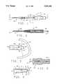
- FIG. 1is is a side elevation of the illumination device of the present invention
- FIG. 2is an enlarged sectional view taken along lines 2--2 of FIG. 1;
- FIG. 3is a an enlarged side elevation of the distal tip of the illumination device of FIG. 1 in use;
- FIG. 4is a view similar to FIG. 3 illustrating how the device functions in part.
- FIG. 5is a partial elevation of the proximal portion of the illumination device of FIG. 1, on an enlarged scale.
- an illumination device 11 of the present inventionincludes a handpiece 13, an illumination light source connector 15, and an optical fiber cable 17.
- Optical fiber cable 17typically includes a protective sheath 19 covering either a single or multiple optical fibers 21.
- a single plastic fiber having a numerical aperture of 0.5 in airis preferred, although multiple fibers or glass fibers could also be used in the present invention.
- a hollow metal probe 25is connected to handpiece 13 and extends distally therefrom. Handpiece 13 is used to manipulate the position of probe 25 to provide illumination passing through the probe to the desired locations during an operation or procedure.
- probe 25is of a size suitable for insertion into a human eye. Illumination devices for other operations and procedures could differ in size.
- illumination device 11is described herein solely as providing illumination, it should be understood that various other features could be added thereto. For example, a pic, an irrigation/aspiration lumen, a laser capability, and various other features could be added as desired.
- optical fiber cable 17terminates proximally in illumination connector 15 in such a manner that it is exposed to illuminating light from the light source.
- the optical cableextends for any desired length (such an eight feet or so) and terminates distally adjacent probe 25.
- Optical fiber cable 17thereby forms an optical path for the illuminating light from the light source to an eye (or other body part or organ).
- sheath 19terminates in handpiece 13 while the optical fiber 21 itself terminates at the distal end of the probe in a bullet-shaped tip 31.
- tip 31is preferably formed on the distal end of optical fiber 21 as described below, it may also be formed as a separate part which is suitably secured to the distal end of probe 25.
- Tip 31is shaped so as to provide uniform illumination over as wide a field of illumination as possible when the tip is disposed under water or some similar liquid.
- bullet-shaped tip 31is optically connected to optical fiber 21 and preferably is an integrally formed part of the optical fiber.
- Tip 31forms the distal end of the optical fiber and has an index of refraction of 1.49 or so.
- the particular values of index of refraction and numerical aperture hereinare for purposes of illustration only, since they will vary depending upon the particular optical fiber being used. It should be appreciated that water (and saline solution) has an index of refraction of 1.33 or so, while air has a refractive index of 1.0.
- Tip 31is shaped to provide even illumination (within twenty per cent or so) over as wide a field as possible in water.
- a field of illumination of 150 degreesis achievable with the present design and is illustrated in FIG. 3.
- the exterior surface of tip 31can be divided into three zones 35, 37 and 39.
- zone 35the curvature of the tip is so slight that substantially all the light passing down optical fiber 21 is internally reflected since all possible angles of incidence are less than the critical angle for the tip in water.
- the critical angleis about 63 degrees.
- transition zone 37Immediately distal of zone 35 is intermediate transition zone 37. In this zone, which is relatively short, total internal reflection stops and some light begins to exit from tip 31. This occurs because the angle of incidence of some light rays in the transition zone exceed the critical angle and those rays are refracted out into the surrounding water.
- Zone 39the remainder of tip 31 distal from zone 37, is the area in which the light exits substantially uniformly from the tip to illuminate the desired portion (labelled 41) of the human body.
- the tip of zone 39is shown as pointed, in fact it is slightly rounded to provide uniform illumination.
- tip 31has an exterior surface which is a surface of revolution of a predetermined curve about the longitudinal axis of the tip.
- the predetermined curveincludes a first proximal segment which generates reflection zone 35, a second intermediate segment which generates transition zone 37, and a third distal segment which generates zone 39.
- the first segment of the generating curvehas tangents substantially all of which make less than a first predetermined angle with the longitudinal axis. This angle is chosen depending upon the material making up the fiber to ensure that substantially all possible light from optical fiber 21 is internally reflected in zone 35.
- the second, transition zone generating segmenthas tangents substantially all of which make angles with the longitudinal axis which are greater than the first predetermined angle and less than a second predetermined angle. These angles are selected to ensure that total internal reflection ceases in the transition zone.
- the third segmenthas tangents substantially all of which make angles with the longitudinal axis which are greater than the second predetermined angle so that in the third zone substantial amounts of light are refracted out of tip 31.
- the generating curvebe a smooth, continuous curve since it has been found that this leads to a more uniform illumination level across the field. Abrupt transitions tend to cause light areas and dark areas by focusing the light preferentially to particular areas. It can also be seen from FIG. 3 that the radii of curvature in the total internal reflection zone, zone 35, are greater than those in zone 37, and that the radii of curvature in zone 37 are greater than those in zone 39. It is preferred that the radii of curvature decrease from proximal end to the distal end of each segment as well so that the angle the tangent to exterior surface of the tip makes with the longitudinal axis of the tip substantially continuously varies from the proximal end of the tip to the distal end of the tip. This provides a complex shape which provides even illumination over a wide field in water.
- optical fiberssuch as fiber 21 include a core and a thin cladding layer.
- the cladding layeris removed so that the optical properties of the tip are not influenced by the cladding, which has a somewhat different index of refraction.
- tip 31 in waterhas a numerical aperture in degrees at least twice the numerical aperture of the optical fiber 21 in water.
- FIG. 4four light rays A, B, C, and D are shown to illustrate some of the characteristics of tip 31.
- transition zone 37is labelled.
- Ray Ais roughly parallel to the longitudinal axis of tip 31 and strikes the surface proximally of the transition zone. Because this is an area of total internal reflection, the ray is reflected toward the distal end of the tip where it strikes the surface and is refracted out.
- Ray Bis parallel to ray A but initially strikes the surface of tip 31 distally of the transition zone and is immediately refracted out of the tip.
- Ray Clike ray A, strikes the surface proximally of the transition zone 37 and is totally internally reflected, even though ray C is incident at a much higher angle than ray A.
- ray Cstrikes the surface distally of zone 37 and is refracted out.
- Ray Dundergoes multiple internal reflections before finally exiting tip 31. It should be appreciated that although ray D is shown exiting near the distal end of the tip, in fact rays which undergo multiple internal reflections may exit the tip at relatively high angles with respect to the axis.
- tip 31is relatively easy to make.
- the end of optical fiber 21is polished (which removes the cladding) in such a manner to approximate the desired bullet shape.
- the tipis then placed in water and the optical fiber tested by shining light therethrough. This generates an illumination pattern under water, which it has been found differs drastically from the illumination pattern for the same tip shape in air.
- the illumination patternis visually compared with the desired uniform illumination pattern. If the generated illumination pattern has excessively bright areas or dark areas, the tip is polished selectively in such a manner as to remove the bright or dark areas and make the illumination under water uniform. It has been found that different generated illumination patterns represent different defects in shape.
- a dark ring disposed around a bright spotindicates that the radii of curvature in zone 39 are too small, while a bright ring disposed around a darker central spot means that radii in zone 39 are too large.
- light source connector 15is shown in more detail. Of special note is the bell-shape 45 of the proximal end of connector 15 which is used to funnel light from the light source into optical fiber 21.
Landscapes
- Physics & Mathematics (AREA)
- Health & Medical Sciences (AREA)
- Engineering & Computer Science (AREA)
- Life Sciences & Earth Sciences (AREA)
- Surgery (AREA)
- Mechanical Engineering (AREA)
- Optics & Photonics (AREA)
- General Physics & Mathematics (AREA)
- Heart & Thoracic Surgery (AREA)
- Medical Informatics (AREA)
- Molecular Biology (AREA)
- Animal Behavior & Ethology (AREA)
- General Health & Medical Sciences (AREA)
- Public Health (AREA)
- Veterinary Medicine (AREA)
- Nuclear Medicine, Radiotherapy & Molecular Imaging (AREA)
- Biomedical Technology (AREA)
- Oral & Maxillofacial Surgery (AREA)
- Pathology (AREA)
- Laser Surgery Devices (AREA)
Abstract
Description
Claims (15)
Priority Applications (1)
| Application Number | Priority Date | Filing Date | Title |
|---|---|---|---|
| US08/049,092US5351168A (en) | 1993-04-16 | 1993-04-16 | Illumination device for surgery |
Applications Claiming Priority (1)
| Application Number | Priority Date | Filing Date | Title |
|---|---|---|---|
| US08/049,092US5351168A (en) | 1993-04-16 | 1993-04-16 | Illumination device for surgery |
Publications (1)
| Publication Number | Publication Date |
|---|---|
| US5351168Atrue US5351168A (en) | 1994-09-27 |
Family
ID=21958009
Family Applications (1)
| Application Number | Title | Priority Date | Filing Date |
|---|---|---|---|
| US08/049,092Expired - LifetimeUS5351168A (en) | 1993-04-16 | 1993-04-16 | Illumination device for surgery |
Country Status (1)
| Country | Link |
|---|---|
| US (1) | US5351168A (en) |
Cited By (28)
| Publication number | Priority date | Publication date | Assignee | Title |
|---|---|---|---|---|
| US5478338A (en)* | 1993-09-24 | 1995-12-26 | Reynard; Michael | Fiber optic sleeve for surgical instruments |
| US5681264A (en)* | 1995-10-25 | 1997-10-28 | Ryan, Jr.; Edwin H. | Shielded illumination device for ophthalmic surgery and the like |
| US5916149A (en)* | 1995-10-25 | 1999-06-29 | Ryan, Jr.; Edwin H. | Shielded illumination device for ophthalmic surgery and the like |
| US5921673A (en)* | 1997-11-13 | 1999-07-13 | Habel; David M. | Illuminated threading tool |
| US5928140A (en)* | 1997-09-02 | 1999-07-27 | Hardten; David R. | Illuminated iris retractor probe system |
| US6050713A (en)* | 1998-05-19 | 2000-04-18 | O'donnell; Joan | Intravenous drip lighting device |
| US6134365A (en)* | 1998-06-01 | 2000-10-17 | Colvin; James Barry | Coherent illumination system and method |
| US6213940B1 (en) | 1996-04-26 | 2001-04-10 | United States Surgical Corporation | Surgical retractor including coil spring suture mount |
| US20020028041A1 (en)* | 2000-09-01 | 2002-03-07 | Easley James C. | Wide angle light diffusing optical fiber tip |
| DE20118502U1 (en) | 2001-11-06 | 2002-04-04 | Nusche, Olaf, 13629 Berlin | lighting device |
| EP1295580A1 (en) | 2001-09-25 | 2003-03-26 | Alcon Inc. | Fiberoptic probe tip |
| US6565508B2 (en) | 1998-01-23 | 2003-05-20 | United States Surgical Corporation | Surgical instrument |
| US20030169603A1 (en)* | 2002-03-05 | 2003-09-11 | Luloh K. Peter | Apparatus and method for illuminating a field of view within an eye |
| US20040160770A1 (en)* | 2003-02-13 | 2004-08-19 | Rodriguez Joel J. | Single intraveneous drip component illumination device |
| EP1672352A1 (en)* | 2004-12-14 | 2006-06-21 | Walter Werne | Device for determining the mixture composition of arbitrary media |
| US7137949B2 (en) | 2001-07-13 | 2006-11-21 | United States Surgical Corporation | Surgical instrument |
| US7294104B2 (en) | 1998-01-23 | 2007-11-13 | United States Surgical Corporation | Surgical instrument holder |
| US20080013900A1 (en)* | 2005-01-21 | 2008-01-17 | Optiscan Pty Ltd. | Fiber bundle for contact endomicroscopy |
| US20080051770A1 (en)* | 2006-08-22 | 2008-02-28 | Synergetics, Inc. | Multiple Target Laser Probe |
| US20080086117A1 (en)* | 2004-09-22 | 2008-04-10 | Cao Group, Inc. | Modular Surgical Laser Systems |
| US20090182313A1 (en)* | 2008-01-15 | 2009-07-16 | Jack Robert Auld | Targeted Illumination For Surgical Instrument |
| US20130137935A1 (en)* | 2011-11-28 | 2013-05-30 | Patrick Haley | Fiber optic illumination device and method of manufacturing |
| US8838212B2 (en) | 2011-05-16 | 2014-09-16 | Bausch & Lomb Incorporated | Apparatus and methods for illuminating substances using color to achieve visual contrast |
| US9364982B2 (en) | 2010-08-09 | 2016-06-14 | Novartis Ag | Method of manufacturing an illuminated surgical instrument |
| US9880337B2 (en) | 2014-01-31 | 2018-01-30 | Ofs Fitel, Llc | Optical fiber assembly, methods of manufacture thereof and articles comprising the same |
| US9956053B2 (en) | 2016-03-04 | 2018-05-01 | Novartis Ag | Cannula with an integrated illumination feature |
| US10244931B2 (en) | 2015-07-13 | 2019-04-02 | Novartis Ag | Illuminated ophthalmic infusion line and associated devices, systems, and methods |
| US11173008B2 (en) | 2015-11-01 | 2021-11-16 | Alcon Inc. | Illuminated ophthalmic cannula |
Citations (15)
| Publication number | Priority date | Publication date | Assignee | Title |
|---|---|---|---|---|
| US3131690A (en)* | 1962-10-22 | 1964-05-05 | American Optical Corp | Fiber optics devices |
| US3439157A (en)* | 1966-02-11 | 1969-04-15 | Singer General Precision | Point light source |
| US3910677A (en)* | 1974-05-13 | 1975-10-07 | Bell Telephone Labor Inc | Hyperbolic type optical fiber lens coupler for coupling the fiber to an optical line source |
| US3932022A (en)* | 1972-11-17 | 1976-01-13 | The Rank Organisation Limited | Light guide arrangement with scanning tip to resist uneven wear |
| US3981709A (en)* | 1974-04-10 | 1976-09-21 | Tokyo Kogaku Kikai Kabushiki Kaisha | Edge processing of chemically toughened lenses |
| JPS57139705A (en)* | 1981-02-24 | 1982-08-28 | Takashi Mori | Optical radiator |
| JPS61248017A (en)* | 1985-04-25 | 1986-11-05 | Olympus Optical Co Ltd | Connector for endoscope |
| US4641912A (en)* | 1984-12-07 | 1987-02-10 | Tsvi Goldenberg | Excimer laser delivery system, angioscope and angioplasty system incorporating the delivery system and angioscope |
| US4678268A (en)* | 1983-10-25 | 1987-07-07 | Consiglio Nazionale Delle Ricerche Roma | Method and apparatus for constructing microlens ends for optical fibers |
| US4693244A (en)* | 1984-05-22 | 1987-09-15 | Surgical Laser Technologies, Inc. | Medical and surgical laser probe I |
| US4693556A (en)* | 1985-06-04 | 1987-09-15 | Laser Therapeutics, Inc. | Apparatus for producing a spherical pattern of light and method of manufacture |
| US4733933A (en)* | 1984-01-20 | 1988-03-29 | Hughes Aircraft Company | Fiber optic structure and method of making |
| US4842390A (en)* | 1987-07-17 | 1989-06-27 | Consiglio Nazionale Delle Ricerche | Fiber optic device for angioplasty |
| US4995691A (en)* | 1989-10-16 | 1991-02-26 | Ensign-Bickford Optics Company | Angled optical fiber input end face and method for delivering energy |
| US5037174A (en)* | 1990-01-31 | 1991-08-06 | E. I. Du Pont De Nemours And Company | Optical fiber having an aspherical lens thereon and method of making same |
- 1993
- 1993-04-16USUS08/049,092patent/US5351168A/ennot_activeExpired - Lifetime
Patent Citations (15)
| Publication number | Priority date | Publication date | Assignee | Title |
|---|---|---|---|---|
| US3131690A (en)* | 1962-10-22 | 1964-05-05 | American Optical Corp | Fiber optics devices |
| US3439157A (en)* | 1966-02-11 | 1969-04-15 | Singer General Precision | Point light source |
| US3932022A (en)* | 1972-11-17 | 1976-01-13 | The Rank Organisation Limited | Light guide arrangement with scanning tip to resist uneven wear |
| US3981709A (en)* | 1974-04-10 | 1976-09-21 | Tokyo Kogaku Kikai Kabushiki Kaisha | Edge processing of chemically toughened lenses |
| US3910677A (en)* | 1974-05-13 | 1975-10-07 | Bell Telephone Labor Inc | Hyperbolic type optical fiber lens coupler for coupling the fiber to an optical line source |
| JPS57139705A (en)* | 1981-02-24 | 1982-08-28 | Takashi Mori | Optical radiator |
| US4678268A (en)* | 1983-10-25 | 1987-07-07 | Consiglio Nazionale Delle Ricerche Roma | Method and apparatus for constructing microlens ends for optical fibers |
| US4733933A (en)* | 1984-01-20 | 1988-03-29 | Hughes Aircraft Company | Fiber optic structure and method of making |
| US4693244A (en)* | 1984-05-22 | 1987-09-15 | Surgical Laser Technologies, Inc. | Medical and surgical laser probe I |
| US4641912A (en)* | 1984-12-07 | 1987-02-10 | Tsvi Goldenberg | Excimer laser delivery system, angioscope and angioplasty system incorporating the delivery system and angioscope |
| JPS61248017A (en)* | 1985-04-25 | 1986-11-05 | Olympus Optical Co Ltd | Connector for endoscope |
| US4693556A (en)* | 1985-06-04 | 1987-09-15 | Laser Therapeutics, Inc. | Apparatus for producing a spherical pattern of light and method of manufacture |
| US4842390A (en)* | 1987-07-17 | 1989-06-27 | Consiglio Nazionale Delle Ricerche | Fiber optic device for angioplasty |
| US4995691A (en)* | 1989-10-16 | 1991-02-26 | Ensign-Bickford Optics Company | Angled optical fiber input end face and method for delivering energy |
| US5037174A (en)* | 1990-01-31 | 1991-08-06 | E. I. Du Pont De Nemours And Company | Optical fiber having an aspherical lens thereon and method of making same |
Cited By (44)
| Publication number | Priority date | Publication date | Assignee | Title |
|---|---|---|---|---|
| US5558669A (en)* | 1993-09-24 | 1996-09-24 | Reynard; Michael | Fiber optic sleeve for surgical instruments |
| US5591160A (en)* | 1993-09-24 | 1997-01-07 | Reynard; Michael | Fiber optic sleeve for surgical instruments |
| US5478338A (en)* | 1993-09-24 | 1995-12-26 | Reynard; Michael | Fiber optic sleeve for surgical instruments |
| US5681264A (en)* | 1995-10-25 | 1997-10-28 | Ryan, Jr.; Edwin H. | Shielded illumination device for ophthalmic surgery and the like |
| US5916149A (en)* | 1995-10-25 | 1999-06-29 | Ryan, Jr.; Edwin H. | Shielded illumination device for ophthalmic surgery and the like |
| US6254530B1 (en) | 1995-10-25 | 2001-07-03 | Edwin H. Ryan, Jr. | Shielded illumination device for ophthalmic surgery and the like |
| US6193650B1 (en) | 1995-10-25 | 2001-02-27 | Edwin H. Ryan, Jr. | Shielded illumination device for ophthalmic surgery and the like |
| US6213940B1 (en) | 1996-04-26 | 2001-04-10 | United States Surgical Corporation | Surgical retractor including coil spring suture mount |
| US6537212B2 (en) | 1996-04-26 | 2003-03-25 | United States Surgical Corporation | Surgical retractor |
| US5928140A (en)* | 1997-09-02 | 1999-07-27 | Hardten; David R. | Illuminated iris retractor probe system |
| US5921673A (en)* | 1997-11-13 | 1999-07-13 | Habel; David M. | Illuminated threading tool |
| US6565508B2 (en) | 1998-01-23 | 2003-05-20 | United States Surgical Corporation | Surgical instrument |
| US7744530B2 (en) | 1998-01-23 | 2010-06-29 | Tyco Healthcare Group Lp | Surgical instrument holder |
| US7294104B2 (en) | 1998-01-23 | 2007-11-13 | United States Surgical Corporation | Surgical instrument holder |
| US6050713A (en)* | 1998-05-19 | 2000-04-18 | O'donnell; Joan | Intravenous drip lighting device |
| US6134365A (en)* | 1998-06-01 | 2000-10-17 | Colvin; James Barry | Coherent illumination system and method |
| US20020028041A1 (en)* | 2000-09-01 | 2002-03-07 | Easley James C. | Wide angle light diffusing optical fiber tip |
| US6829411B2 (en) | 2000-09-01 | 2004-12-07 | Syntec, Inc. | Wide angle light diffusing optical fiber tip |
| US7137949B2 (en) | 2001-07-13 | 2006-11-21 | United States Surgical Corporation | Surgical instrument |
| EP1295580A1 (en) | 2001-09-25 | 2003-03-26 | Alcon Inc. | Fiberoptic probe tip |
| US6730076B2 (en) | 2001-09-25 | 2004-05-04 | Alcon, Inc. | Fiberoptic probe tip |
| DE20118502U1 (en) | 2001-11-06 | 2002-04-04 | Nusche, Olaf, 13629 Berlin | lighting device |
| US20030169603A1 (en)* | 2002-03-05 | 2003-09-11 | Luloh K. Peter | Apparatus and method for illuminating a field of view within an eye |
| US20050117335A1 (en)* | 2003-02-13 | 2005-06-02 | Rodriquez Joel J. | Intravenous drip component illumination device |
| US7052158B2 (en) | 2003-02-13 | 2006-05-30 | Embo-Optics, Llc | Intravenous drip component illumination device |
| US6877877B2 (en) | 2003-02-13 | 2005-04-12 | Embo-Optics, Llc | Single intraveneous drip component illumination device |
| US20040160770A1 (en)* | 2003-02-13 | 2004-08-19 | Rodriguez Joel J. | Single intraveneous drip component illumination device |
| US20080086117A1 (en)* | 2004-09-22 | 2008-04-10 | Cao Group, Inc. | Modular Surgical Laser Systems |
| EP1672352A1 (en)* | 2004-12-14 | 2006-06-21 | Walter Werne | Device for determining the mixture composition of arbitrary media |
| US20080013900A1 (en)* | 2005-01-21 | 2008-01-17 | Optiscan Pty Ltd. | Fiber bundle for contact endomicroscopy |
| US20080051770A1 (en)* | 2006-08-22 | 2008-02-28 | Synergetics, Inc. | Multiple Target Laser Probe |
| US9402643B2 (en) | 2008-01-15 | 2016-08-02 | Novartis Ag | Targeted illumination for surgical instrument |
| US20090182313A1 (en)* | 2008-01-15 | 2009-07-16 | Jack Robert Auld | Targeted Illumination For Surgical Instrument |
| US9510848B2 (en) | 2008-01-15 | 2016-12-06 | Novartis Ag | Targeted illumination for surgical instrument |
| US9510847B2 (en) | 2008-01-15 | 2016-12-06 | Novartis Ag | Targeted illumination for surgical instrument |
| US9364982B2 (en) | 2010-08-09 | 2016-06-14 | Novartis Ag | Method of manufacturing an illuminated surgical instrument |
| US8838212B2 (en) | 2011-05-16 | 2014-09-16 | Bausch & Lomb Incorporated | Apparatus and methods for illuminating substances using color to achieve visual contrast |
| US20130137935A1 (en)* | 2011-11-28 | 2013-05-30 | Patrick Haley | Fiber optic illumination device and method of manufacturing |
| US9888837B2 (en)* | 2011-11-28 | 2018-02-13 | I-Tek Medical Solutions, Inc. | Fiber optic illumination device and method of manufacturing |
| US9880337B2 (en) | 2014-01-31 | 2018-01-30 | Ofs Fitel, Llc | Optical fiber assembly, methods of manufacture thereof and articles comprising the same |
| US9921354B2 (en) | 2014-01-31 | 2018-03-20 | Ofs Fitel, Llc | Optical fiber assembly, methods of manufacture thereof and articles comprising the same |
| US10244931B2 (en) | 2015-07-13 | 2019-04-02 | Novartis Ag | Illuminated ophthalmic infusion line and associated devices, systems, and methods |
| US11173008B2 (en) | 2015-11-01 | 2021-11-16 | Alcon Inc. | Illuminated ophthalmic cannula |
| US9956053B2 (en) | 2016-03-04 | 2018-05-01 | Novartis Ag | Cannula with an integrated illumination feature |
Similar Documents
| Publication | Publication Date | Title |
|---|---|---|
| US5351168A (en) | Illumination device for surgery | |
| US12251273B2 (en) | Illuminated suction apparatus | |
| US6004315A (en) | Optical fiber diffuser and method of making | |
| EP0248520B1 (en) | Endophotocoagulation probe | |
| US3131690A (en) | Fiber optics devices | |
| US4772093A (en) | Fiber-optic image-carrying device | |
| US8936551B2 (en) | Illuminated suction apparatus | |
| US5873877A (en) | Medical probe device with transparent distal extremity | |
| AU604782B2 (en) | Wire guided laser catheter | |
| US4878725A (en) | Apparatus for the circumferential irradiation of objects | |
| US3136310A (en) | Optical catheter | |
| US4046150A (en) | Medical instrument for locating and removing occlusive objects | |
| CN109496259A (en) | Flat illumination device for ophthalmologic operation | |
| WO1998048690A1 (en) | Transilluminating bougie | |
| GB2208805A (en) | Laser catheter | |
| JPH06343651A (en) | Fiberoptic probe for laser operation of pulpy tissue | |
| US5681264A (en) | Shielded illumination device for ophthalmic surgery and the like | |
| CN106659536A (en) | Fiber optic laser surgical instrument having a radial dispersion pattern | |
| CA1275589C (en) | Fiber-optic image-carrying device |
Legal Events
| Date | Code | Title | Description |
|---|---|---|---|
| STPP | Information on status: patent application and granting procedure in general | Free format text:APPLICATION UNDERGOING PREEXAM PROCESSING | |
| AS | Assignment | Owner name:INFINITECH, INC., MISSOURI Free format text:ASSIGNMENT OF ASSIGNORS INTEREST;ASSIGNOR:EASLEY, JAMES C.;REEL/FRAME:006589/0709 Effective date:19930616 | |
| FPAY | Fee payment | Year of fee payment:4 | |
| FEPP | Fee payment procedure | Free format text:PAYOR NUMBER ASSIGNED (ORIGINAL EVENT CODE: ASPN); ENTITY STATUS OF PATENT OWNER: LARGE ENTITY | |
| AS | Assignment | Owner name:INNOVATION MEDICAL TECHNOLOGIES,INC., TEXAS Free format text:MERGER;ASSIGNORS:INFINITECH,INC.;SURGICAL TECHNOLOGY,INC.;REEL/FRAME:009711/0429 Effective date:19981231 | |
| AS | Assignment | Owner name:ALCON LABORATORIES, INC., TEXAS Free format text:MERGER;ASSIGNOR:INNOVATION MEDICAL TECHNOLOGIES, INC.;REEL/FRAME:009737/0020 Effective date:19981231 Owner name:ALCON LABORATORIES, INC., TEXAS Free format text:MERGER;ASSIGNOR:INNOVATION MEDICAL TECHNOLOGIES, INC.;REEL/FRAME:009737/0012 Effective date:19981231 | |
| AS | Assignment | Owner name:ALCON LABORATORIES, INC., TEXAS Free format text:MERGER;ASSIGNOR:INNOVATION MEDICAL TECHNOLOGIES, INC.;REEL/FRAME:009764/0553 Effective date:19981231 | |
| FEPP | Fee payment procedure | Free format text:PAYER NUMBER DE-ASSIGNED (ORIGINAL EVENT CODE: RMPN); ENTITY STATUS OF PATENT OWNER: LARGE ENTITY Free format text:PAYOR NUMBER ASSIGNED (ORIGINAL EVENT CODE: ASPN); ENTITY STATUS OF PATENT OWNER: LARGE ENTITY | |
| AS | Assignment | Owner name:ALCON MANUFACTURING, LTD., TEXAS Free format text:ASSIGNMENT OF ASSIGNORS INTEREST;ASSIGNOR:ALCON LABORATORIES, INC.;REEL/FRAME:011667/0559 Effective date:20010322 | |
| FEPP | Fee payment procedure | Free format text:PAT HOLDER NO LONGER CLAIMS SMALL ENTITY STATUS, ENTITY STATUS SET TO UNDISCOUNTED (ORIGINAL EVENT CODE: STOL); ENTITY STATUS OF PATENT OWNER: LARGE ENTITY | |
| FPAY | Fee payment | Year of fee payment:8 | |
| REMI | Maintenance fee reminder mailed | ||
| FPAY | Fee payment | Year of fee payment:12 | |
| AS | Assignment | Owner name:ALCON RESEARCH, LTD., TEXAS Free format text:MERGER;ASSIGNOR:ALCON MANUFACTURING, LTD.;REEL/FRAME:021266/0729 Effective date:20080101 Owner name:ALCON RESEARCH, LTD.,TEXAS Free format text:MERGER;ASSIGNOR:ALCON MANUFACTURING, LTD.;REEL/FRAME:021266/0729 Effective date:20080101 |