US5350301A - Method and apparatus for applying a direction-adjusting extension piece in a dental implant - Google Patents
Method and apparatus for applying a direction-adjusting extension piece in a dental implantDownload PDFInfo
- Publication number
- US5350301A US5350301AUS08/108,796US10879693AUS5350301AUS 5350301 AUS5350301 AUS 5350301AUS 10879693 AUS10879693 AUS 10879693AUS 5350301 AUS5350301 AUS 5350301A
- Authority
- US
- United States
- Prior art keywords
- extension piece
- arrangement according
- screw thread
- implant
- extension
- Prior art date
- Legal status (The legal status is an assumption and is not a legal conclusion. Google has not performed a legal analysis and makes no representation as to the accuracy of the status listed.)
- Expired - Lifetime
Links
Images


Classifications
- A—HUMAN NECESSITIES
- A61—MEDICAL OR VETERINARY SCIENCE; HYGIENE
- A61C—DENTISTRY; APPARATUS OR METHODS FOR ORAL OR DENTAL HYGIENE
- A61C8/00—Means to be fixed to the jaw-bone for consolidating natural teeth or for fixing dental prostheses thereon; Dental implants; Implanting tools
- A61C8/0048—Connecting the upper structure to the implant, e.g. bridging bars
- A61C8/005—Connecting devices for joining an upper structure with an implant member, e.g. spacers
- A61C8/0066—Connecting devices for joining an upper structure with an implant member, e.g. spacers with positioning means
- A—HUMAN NECESSITIES
- A61—MEDICAL OR VETERINARY SCIENCE; HYGIENE
- A61C—DENTISTRY; APPARATUS OR METHODS FOR ORAL OR DENTAL HYGIENE
- A61C8/00—Means to be fixed to the jaw-bone for consolidating natural teeth or for fixing dental prostheses thereon; Dental implants; Implanting tools
- A61C8/0048—Connecting the upper structure to the implant, e.g. bridging bars
- A61C8/005—Connecting devices for joining an upper structure with an implant member, e.g. spacers
- A61C8/0053—Connecting devices for joining an upper structure with an implant member, e.g. spacers with angular adjustment means, e.g. ball and socket joint
- A—HUMAN NECESSITIES
- A61—MEDICAL OR VETERINARY SCIENCE; HYGIENE
- A61C—DENTISTRY; APPARATUS OR METHODS FOR ORAL OR DENTAL HYGIENE
- A61C8/00—Means to be fixed to the jaw-bone for consolidating natural teeth or for fixing dental prostheses thereon; Dental implants; Implanting tools
- A61C8/0048—Connecting the upper structure to the implant, e.g. bridging bars
- A61C8/005—Connecting devices for joining an upper structure with an implant member, e.g. spacers
- A61C8/006—Connecting devices for joining an upper structure with an implant member, e.g. spacers with polygonal positional means, e.g. hexagonal or octagonal
Definitions
- This inventionrelates to a method for applying a direction-adjusting extension piece in dental implants and to the elements used thereby.
- the known methods for fixedly connecting dentures to a toothless jawcan, among other things, exist in implanting, after opening the mucosa or mucous membrane, of a cylindrical structure from a bio-compatible material, for instance titanium, in the bone of the upper or lower jaw, whereby this cylinder-shaped structure is completely countersunk in the bone, after which the mucosa or mucous membrane is sewn up and a waiting period of approximately six months is required, in order to allow the bone to grow together, osseo-integrate respectively, with the implanted structure.
- a bio-compatible materialfor instance titanium
- the mucosa or mucous membraneis re-opened at the implant, and a temporary extension piece is screwed in the implant, after which the mucous membrane is sewn up again around this temporary extension piece.
- a temporary extension pieceis used for obtaining, during the healing process of the mucous membrane, a correct transmucosal diameter.
- the temporary extension pieceis replaced with a definitive extension piece with the required length.
- Both the temporary and the definitive extension piecesare screwed in along the axis of the implant.
- the definitive extension pieceis provided occlusally with internal screw threads upon which the proper dentures can be screwed in the direction of the axis of the implant.
- a bridge structurefor instance in the form of a tooth ring, to be screwed in.
- small holesare provided through which a prosthesis screw is applied for connecting the tooth ring to each implant.
- the above applied prosthesis screwsare usually screwed tight in the direction of the axis of the extension piece, so that the axis direction of the implant determines the axis direction of the extension piece and thus also the axis direction of the tooth placed thereupon with the prosthesis screw.
- the bone quality, the bone volume and the anatomic limitations of the lower and especially upper jawsometimes force the surgeon to place the implant at a location not corresponding to the natural location of the former tooth position, thus causing afterwards functional, hygienic and aesthetic complications in the prosthetic field.
- the access for the screwis provided at unwanted places, and the axis direction of the connected dentures will also be unfavorable, thus causing aesthetic problems.
- pre-formed and inclined extension piecesare known, which are glued in the implant, having as a disadvantage, however, that a permanent connection is obtained.
- bendable extension pieces with a thin neckare known, which can be screwed in the implant, however, they have been found to break easily.
- deformable or grindable synthetic extension piecesare known, which are cast in metal through a lost wax casting technique, so that an individual extension piece is obtained, which is breakable, however, and usually fits badly in the implant. Moreover, this method is time-consuming and the extension pieces are not reproduceable if a replacement is necessary.
- extension piecesare provided with a ball joint which can be locked. These extension pieces present the disadvantage that they are very complex and very breakable due to their small dimensions.
- the present inventionaims at a method and elements used thereby which provide a solution for applying direction-adjusting extension pieces.
- the inventionrelates to a method for applying a direction-adjusting extension piece in a dental implant, which mainly consists in screwing an orientation axle, provided with marks, in an implant; determining the required axis correction; screwing the orientation axle out and screwing a direction-adjusting extension piece in the implant, thus obtaining the necessary axis adjustment.
- the elements which are used with this methodinclude, on the one hand, an orientation axle with marks and, on the other hand, a series of direction-adjusting extension pieces which allow consecutively an axis correction according to one of the marks on the orientation axle.
- FIG. 1shows a schematic representation of an orientation axle according to the invention in perspective
- FIG. 2represents a cross-section according to line II--II in FIG. 1;
- FIG. 3is a schematic representation of a direction-adjusting extension piece according to the invention.
- FIG. 4represents a cross-section according to line IV--IV in FIG. 3;
- FIGS. 5 and 6represent cross-sections similar to that of FIG. 4, but for different embodiments
- FIG. 7represents a cross-section in an exploded view of a dental implant with an orientation axle according to the invention.
- FIG. 8represents a cross-section to a larger scale of an orientation axle mounted in a dental implant
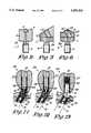
- FIG. 9represents a cross-section in an exploded view of a dental implant and a direction-adjusting extension piece with supra-structure
- FIG. 10represents a cross-section to a larger scale of a direction-adjusting extension piece mounted in a dental implant, and of the corresponding supra-structure;
- FIG. 11represents a view similar to that of FIG. 10, in which the direction-adjusting extension piece according to FIG. 4 is used;
- FIG. 12represents a view similar to that of FIG. 10, in which the direction-adjusting extension piece according to FIG. 5 is used;
- FIG. 13represents a view similar to that of FIG. 10, in which yet another direction-adjusting extension piece is used.
- an orientation axle 1as represented schematically in FIG. 1 which consists of, on the one hand, a screw thread part 2, and, on the other hand, of a cylindrical body 3 with flat top 4 on which marks 5 are provided.
- these marks 5consist of radial stripes 6 applied to the flat top 4 with a corresponding identification element 7, such as for instance numbers or letters, in this case the letters A to H.
- the flat top 4can be provided with a hole 8, for instance a hexagon, to facilitate the screwing in and out of the orientation axle.
- the marks 6can be continued on the circumference of the cylindrical body 3.
- FIGS. 3 and 4represent a schematic view of a first direction-adjusting extension piece 9 according to the invention, which is used with the method according to the invention.
- This extension piece 9consists of, on the one hand, a screw thread part 10 which is identical to the screw thread part 2 of the orientation axle 1, on which a head 11 is provided, and, on the other hand, of a proper direction-adjusting element 12 connected to this head 11, which is provided with a screw thread 13 directed aslant in relation to the axis of the extension piece 9.
- the direction-adjusting element 12is provided at its upper surface with a mark 14 which can correspond to one of the marks 5 of the orientation axle 1 and which is preferably provided in a similar manner with an indication, in this case the indication A, which implies that this extension piece corresponds to a correction mark A of the orientation axle 1.
- FIG. 5represents a direction-adjusting extension piece, which merely differs from the extension piece in FIG. 4 in that its upper surface is directed aslant, more specifically at right angles to the heart line of the screw thread 13.
- FIG. 6represents a direction-adjusting extension piece which will be discussed in further detail hereafter.
- the orientation axle 1can be formed automatically in one part.
- the screw thread part 2 provided at the bottom of the orientation axle 1is manufactured in such a way that it is in accordance with the inner screw thread of the implant with which it is used.
- This orientation axle 1is screwed in a mother matrix, for instance a plate, up to a fixed stop formed by the lower surface of the body 3 of the orientation axle 1.
- the mother matrixis provided around the orientation axle 1 screwed therein, with marks, for instance stripes, which can be similarily applied on the orientation axle 1, for instance by means of a laser technique, etching, scratching or the like.
- orientation axle 1is screwed out of the mother matrix and can be used as such.
- the mother matrixis then used for manufacturing the direction-adjusting extension pieces 9.
- the screw thread part 10 of the head 11is screwed in the mother matrix, more specifically in the screw thread hole in which the orientation axle 1 was screwed, up to a fixed stop formed by the lower surface of head 11.
- the proper direction-adjusting element 12is placed on top of the basic screw thread part 10 and orientated thereupon by placing the mark 14 of element 12 opposite to one of the marks applied in the mother matrix, in this case A to H.
- the marksare standardized on the mother matrix and thus also with respect to the coils of the screw thread parts 2 and 10 of the orientation axle 1 and the head 11 respectively.
- Both the head 11 and the actual direction-adjusting part 12 of the extension piece 9are manufactured automatically.
- these partsare permanently connected, for instance by means of glueing, soldering or a laser technique, to form the complete extension piece 9, after which this extension piece 9 is screwed out of the mother matrix.
- direction-adjusting extension pieces 9will be formed, whose axis adjustment corresponds to one of the marks, in other words extension pieces A, B, C, D, E, F, G and H.
- FIGS. 7 and 8are schematic representations of a dental implant 15 which is applied in the bone 16 of the upper or lower jaw and which is already fully integrated therein.
- the bone 16is covered at the top with the mucosa or mucous membrane 18 which has been opened at the implant 15 so that the end 20 of the implant, provided with internal screw thread 19, can be reached via the mouth.
- an orientation axle 1is subsequently applied in the end 20 of the implant 15, as represented in FIGS. 7 and 8.
- the screw thread parts 2 and 19 of the orientation axle 1 and the implant 15are similar to one another and can only be screwed together from a particular position until the lower surface of the cylindrical body 3 of the orientation axle 1 forms a stop against the upper surface of the implant 15. This causes the orientation axle 1 to be in one specific orientation.
- This orientation axle 1can be freely screwed in or out of the implant 15, or even be replaced with an other orientation axle 1, whose marks are also standardized.
- the dentistcan then decide which correction of the implantation axis 17 has to be executed and determine the corresponding direction-adjusting extension piece with the help of the marks 5 applied on the orientation axle 1.
- the dentistwill read a mark, for instance A, so that he knows that a corresponding direction-adjusting extension piece A will have to be used.
- the orientation axle 1is screwed out of the implant and, as represented in FIGS. 9 and 10, replaced by a direction-adjusting extension piece 9, which is screwed in the implant 15 with its screw thread part 10, until the bottom part of the head 11 of this extension piece 9 forms a stop against the implant 15.
- the axis correctionis therefore automatically obtained since the aslant directed screw thread 13 is directed perpendicularly or almost perpendicularly to the bone 16.
- the actual direction-adjusting element 12is provided with a central part 21 in which for instance a transverse groove 22 is applied allowing for the extension piece 9 to be rotated by means of a fit tool, while around the central part 21 a cylindrical groove 23 is provided, a side edge of which is directed aslant.
- a supra-structure 24is connected by means of a prosthesis screw 25 which is screwed in the screw thread 13 of the extension piece 9, so that the axis 26 of the applied supra-structure 24 is identical to the direction previously determined, being the axis direction of the natural direction of the tooth 27.
- the supra-structure 24consists of a hollow support 28, whose lower extremity has a circumferential rib 29 with a slanting side edge, cooperating with the groove 23 in the extension piece 9 in order to position the hollow support 28 effectively with respect to the extension piece 9.
- the lower extremity of the hollow support 28has a slanting structure in this embodiment which can be connected to the extension piece 9.
- the actual tooth 27is maintained on the hollow structure 28, for instance by means of baked porcelain.
- cavity 30will eventually be provided with a suitable filling 31.
- FIG. 11represents an embodiment of a supra-structure 24 which is meant to be used with a direction-adjusting extension piece 9 according to the embodiment of FIG. 4, whereas FIG. 12 represents an embodiment whereby the supra-structure 24 cooperates with a direction-adjusting extension piece 9 according to the embodiment represented in FIG. 5.
- FIG. 13represents a supra-structure 24 which will be used with a direction-adjusting extension piece 9 which is obtained and applied in the same way as described above, and whereby use is made of a conical axle 32 replacing the screw thread 13 and upon which the supra-structure 24 is maintained by clenching the conical hole 33 on the conical axle 32.
- both the orientation axle 1 and the direction correcting extension pieces 9are preferably provided with a slanting edge 34 which facilitates the penetration of these parts in the mucosa or mucous membrane.
Landscapes
- Health & Medical Sciences (AREA)
- Oral & Maxillofacial Surgery (AREA)
- Orthopedic Medicine & Surgery (AREA)
- Dentistry (AREA)
- Epidemiology (AREA)
- Life Sciences & Earth Sciences (AREA)
- Animal Behavior & Ethology (AREA)
- General Health & Medical Sciences (AREA)
- Public Health (AREA)
- Veterinary Medicine (AREA)
- Dental Prosthetics (AREA)
Abstract
Description
Claims (18)
Applications Claiming Priority (2)
| Application Number | Priority Date | Filing Date | Title |
|---|---|---|---|
| BE09200726 | 1992-08-19 | ||
| BE9200726ABE1006129A3 (en) | 1992-08-19 | 1992-08-19 | Method for applying a richtingkorrigerend lens in a dentaalimplantaat elements and hereby apply. |
Publications (1)
| Publication Number | Publication Date |
|---|---|
| US5350301Atrue US5350301A (en) | 1994-09-27 |
Family
ID=3886400
Family Applications (1)
| Application Number | Title | Priority Date | Filing Date |
|---|---|---|---|
| US08/108,796Expired - LifetimeUS5350301A (en) | 1992-08-19 | 1993-08-19 | Method and apparatus for applying a direction-adjusting extension piece in a dental implant |
Country Status (4)
| Country | Link |
|---|---|
| US (1) | US5350301A (en) |
| EP (1) | EP0583829B1 (en) |
| BE (1) | BE1006129A3 (en) |
| DE (1) | DE69322558T2 (en) |
Cited By (18)
| Publication number | Priority date | Publication date | Assignee | Title |
|---|---|---|---|---|
| US5571015A (en)* | 1994-09-26 | 1996-11-05 | Siegmund; Ernie | Dental replacement mounting system |
| US5622499A (en)* | 1995-04-10 | 1997-04-22 | Simmons; William E. | Method of manufacturing a dental abutment |
| US5695334A (en)* | 1995-12-08 | 1997-12-09 | Blacklock; Gordon D. | Bendable and castable post and core |
| US5716215A (en)* | 1996-03-15 | 1998-02-10 | Blacklock; Gordon D. | Machinable post and core |
| US5876204A (en)* | 1997-11-25 | 1999-03-02 | Sulzer Calcitek Inc. | Dental implant positioning guide |
| US5908298A (en)* | 1995-03-17 | 1999-06-01 | Duerr; Walter | Enossal single tooth implant with spacer sleeve |
| US6280194B1 (en)* | 1997-11-11 | 2001-08-28 | Nobel Biocare Ab | Arrangement and its use for anchoring a threaded implant in bone, for example dentine |
| US6406295B1 (en)* | 2001-07-13 | 2002-06-18 | Brian A. Mahler | Identification of dental implant components |
| US6814577B2 (en) | 2002-10-09 | 2004-11-09 | Gordon D. Blacklock | Dental prosthesis abutment and waxing sleeve assembly |
| US20060015112A1 (en)* | 2003-01-29 | 2006-01-19 | Mcgovern Michael A | Apparatus and method for preparing bone for anti-rotational implantation of an orthopedic endoprosthesis |
| US6994547B1 (en)* | 1999-10-21 | 2006-02-07 | Ashok Sethi | Implant alignment |
| US6997710B2 (en) | 2002-07-29 | 2006-02-14 | Americo Fernendes | Dental prosthesis post and core assembly |
| US20060121417A1 (en)* | 2004-01-19 | 2006-06-08 | Gabriele Scommegna | Dental implant |
| US20100129774A1 (en)* | 2007-05-24 | 2010-05-27 | Martinez Maria Auxiliadora Mourao | System of compensatory slanted copings, converters and extenders and abutments of universal coupling over osseointegrated implants |
| US20140205969A1 (en)* | 2012-11-20 | 2014-07-24 | Gerald M. Marlin | Universal Aligning Adaptor System and Methods |
| US20140302458A1 (en)* | 2013-04-09 | 2014-10-09 | Biomet 3I, Llc | Dental Implant With Coded Upper Surface |
| USD734462S1 (en)* | 2013-08-20 | 2015-07-14 | Medical Corporation It | Guide member for a dental drill |
| US20230025033A1 (en)* | 2021-07-26 | 2023-01-26 | United States Of American As Represented By The Secretary Of The Navy | Dental implant identification system |
Families Citing this family (8)
| Publication number | Priority date | Publication date | Assignee | Title |
|---|---|---|---|---|
| US6790040B2 (en) | 1999-11-10 | 2004-09-14 | Implant Innovations, Inc. | Healing components for use in taking impressions and methods for making the same |
| SE528719C2 (en)* | 2005-06-03 | 2007-01-30 | Nobel Biocare Services Ag | Device for implants extending between a dental installation and the zygoma |
| JP5175291B2 (en)* | 2006-11-03 | 2013-04-03 | マテリアライズ・デンタル・ナムローゼ・フエンノートシャップ | Dental attachment assembly |
| NL2002019C (en) | 2008-09-25 | 2010-03-29 | Biocomp Ind B V | IMPLANT CONSTRUCTION. |
| EP2494938A1 (en)* | 2011-03-03 | 2012-09-05 | Astra Tech AB | Dental implant assembly |
| US8944816B2 (en) | 2011-05-16 | 2015-02-03 | Biomet 3I, Llc | Temporary abutment with combination of scanning features and provisionalization features |
| US9839496B2 (en) | 2013-02-19 | 2017-12-12 | Biomet 3I, Llc | Patient-specific dental prosthesis and gingival contouring developed by predictive modeling |
| EP3998040B1 (en) | 2013-12-20 | 2025-09-03 | Biomet 3i, LLC | Dental method for developing custom prostheses through scanning of coded members |
Citations (8)
| Publication number | Priority date | Publication date | Assignee | Title |
|---|---|---|---|---|
| US4187609A (en)* | 1975-03-17 | 1980-02-12 | Edelman Alfred E | Submerged functional implant and method |
| EP0198306A2 (en)* | 1981-08-14 | 1986-10-22 | TATUM, O Hilt Jr. | Dental implant |
| US4734035A (en)* | 1986-04-09 | 1988-03-29 | Cheng Fat Hing | Endodontic stop positioner |
| EP0313222A2 (en)* | 1987-09-24 | 1989-04-26 | Steven Gorgas Detsch | Dental implant attachment system |
| US5018970A (en)* | 1987-12-17 | 1991-05-28 | Stordahl Finn R | Implant teeth--permanent bases with replaceable caps |
| US5030095A (en)* | 1989-08-16 | 1991-07-09 | Niznick Gerald A | Angled abutment for endosseous implants |
| WO1992009242A1 (en)* | 1990-11-21 | 1992-06-11 | Tatum O Hilt Iii | Rotary dental implant post |
| US5215460A (en)* | 1991-11-20 | 1993-06-01 | Perry William L | Method for paralleling implant restorative components |
- 1992
- 1992-08-19BEBE9200726Apatent/BE1006129A3/enactive
- 1993
- 1993-08-13DEDE69322558Tpatent/DE69322558T2/ennot_activeExpired - Fee Related
- 1993-08-13EPEP93202371Apatent/EP0583829B1/ennot_activeExpired - Lifetime
- 1993-08-19USUS08/108,796patent/US5350301A/ennot_activeExpired - Lifetime
Patent Citations (8)
| Publication number | Priority date | Publication date | Assignee | Title |
|---|---|---|---|---|
| US4187609A (en)* | 1975-03-17 | 1980-02-12 | Edelman Alfred E | Submerged functional implant and method |
| EP0198306A2 (en)* | 1981-08-14 | 1986-10-22 | TATUM, O Hilt Jr. | Dental implant |
| US4734035A (en)* | 1986-04-09 | 1988-03-29 | Cheng Fat Hing | Endodontic stop positioner |
| EP0313222A2 (en)* | 1987-09-24 | 1989-04-26 | Steven Gorgas Detsch | Dental implant attachment system |
| US5018970A (en)* | 1987-12-17 | 1991-05-28 | Stordahl Finn R | Implant teeth--permanent bases with replaceable caps |
| US5030095A (en)* | 1989-08-16 | 1991-07-09 | Niznick Gerald A | Angled abutment for endosseous implants |
| WO1992009242A1 (en)* | 1990-11-21 | 1992-06-11 | Tatum O Hilt Iii | Rotary dental implant post |
| US5215460A (en)* | 1991-11-20 | 1993-06-01 | Perry William L | Method for paralleling implant restorative components |
Cited By (30)
| Publication number | Priority date | Publication date | Assignee | Title |
|---|---|---|---|---|
| US5571015A (en)* | 1994-09-26 | 1996-11-05 | Siegmund; Ernie | Dental replacement mounting system |
| US5908298A (en)* | 1995-03-17 | 1999-06-01 | Duerr; Walter | Enossal single tooth implant with spacer sleeve |
| US5622499A (en)* | 1995-04-10 | 1997-04-22 | Simmons; William E. | Method of manufacturing a dental abutment |
| US5695334A (en)* | 1995-12-08 | 1997-12-09 | Blacklock; Gordon D. | Bendable and castable post and core |
| US5716215A (en)* | 1996-03-15 | 1998-02-10 | Blacklock; Gordon D. | Machinable post and core |
| US6280194B1 (en)* | 1997-11-11 | 2001-08-28 | Nobel Biocare Ab | Arrangement and its use for anchoring a threaded implant in bone, for example dentine |
| US5876204A (en)* | 1997-11-25 | 1999-03-02 | Sulzer Calcitek Inc. | Dental implant positioning guide |
| US6994547B1 (en)* | 1999-10-21 | 2006-02-07 | Ashok Sethi | Implant alignment |
| US6406295B1 (en)* | 2001-07-13 | 2002-06-18 | Brian A. Mahler | Identification of dental implant components |
| US6997710B2 (en) | 2002-07-29 | 2006-02-14 | Americo Fernendes | Dental prosthesis post and core assembly |
| US6814577B2 (en) | 2002-10-09 | 2004-11-09 | Gordon D. Blacklock | Dental prosthesis abutment and waxing sleeve assembly |
| US7955338B2 (en)* | 2003-01-29 | 2011-06-07 | Howmedica Osteoenics Corp. | Apparatus and method for preparing bone for anti-rotational implantation of an orthopedic endoprosthesis |
| US20060015112A1 (en)* | 2003-01-29 | 2006-01-19 | Mcgovern Michael A | Apparatus and method for preparing bone for anti-rotational implantation of an orthopedic endoprosthesis |
| US8328556B2 (en)* | 2004-01-19 | 2012-12-11 | Leone S.P.A. | Dental implant |
| US20060121417A1 (en)* | 2004-01-19 | 2006-06-08 | Gabriele Scommegna | Dental implant |
| US9603678B2 (en)* | 2007-05-24 | 2017-03-28 | ITP—Instituto de Tecnologia e Pesquisa LTDA | System of compensatory slanted copings, converters and extenders and abutments of universal coupling over osseointegrated implants |
| US20100129774A1 (en)* | 2007-05-24 | 2010-05-27 | Martinez Maria Auxiliadora Mourao | System of compensatory slanted copings, converters and extenders and abutments of universal coupling over osseointegrated implants |
| US20140205969A1 (en)* | 2012-11-20 | 2014-07-24 | Gerald M. Marlin | Universal Aligning Adaptor System and Methods |
| US11666419B2 (en) | 2012-11-20 | 2023-06-06 | Gerald M. Marlin | Universal aligning adaptor system and methods |
| US10390908B2 (en) | 2012-11-20 | 2019-08-27 | Gerald M. Marlin | Universal aligning adaptor system and methods |
| US9364299B2 (en)* | 2012-11-20 | 2016-06-14 | Gerald M. Marlin | Universal aligning adaptor system and methods |
| EP2983611A4 (en)* | 2013-04-09 | 2016-11-30 | Biomet 3I Llc | DENTAL IMPLANT HAVING UPPER CODED SURFACE |
| US11065090B2 (en)* | 2013-04-09 | 2021-07-20 | Biom et 3I, LLC | Dental implant with coded upper surface |
| US20210307879A1 (en)* | 2013-04-09 | 2021-10-07 | Biomet 3I, Llc | Dental implant with coded upper surface |
| US20140302458A1 (en)* | 2013-04-09 | 2014-10-09 | Biomet 3I, Llc | Dental Implant With Coded Upper Surface |
| US11864975B2 (en)* | 2013-04-09 | 2024-01-09 | Biomet 3I, Llc | Dental implant with coded upper surface |
| US20240108443A1 (en)* | 2013-04-09 | 2024-04-04 | Biomet 3I, Llc | Dental implant with coded upper surface |
| US12303353B2 (en)* | 2013-04-09 | 2025-05-20 | Biomet 3I, Llc | Dental implant with coded upper surface |
| USD734462S1 (en)* | 2013-08-20 | 2015-07-14 | Medical Corporation It | Guide member for a dental drill |
| US20230025033A1 (en)* | 2021-07-26 | 2023-01-26 | United States Of American As Represented By The Secretary Of The Navy | Dental implant identification system |
Also Published As
| Publication number | Publication date |
|---|---|
| BE1006129A3 (en) | 1994-05-17 |
| EP0583829B1 (en) | 1998-12-16 |
| DE69322558D1 (en) | 1999-01-28 |
| DE69322558T2 (en) | 1999-06-17 |
| EP0583829A1 (en) | 1994-02-23 |
Similar Documents
| Publication | Publication Date | Title |
|---|---|---|
| US5350301A (en) | Method and apparatus for applying a direction-adjusting extension piece in a dental implant | |
| KR101881421B1 (en) | Abutment assembly | |
| US5651675A (en) | Healing cap system | |
| US4431416A (en) | Endosseous dental implant system for overdenture retention, crown and bridge support | |
| US4608972A (en) | Method of applying a chin implant, drill guide tool and implant | |
| US5674073A (en) | Impression coping | |
| EP0967931B1 (en) | Anatomical restoration dental implant system for posterior and anterior teeth | |
| KR100909912B1 (en) | Implants for use on the aesthetics of the mouth | |
| US6129548A (en) | Two-piece healing abutment system | |
| US6283752B1 (en) | Universal impression coping system | |
| EP0473262B1 (en) | Dental implant collar and post system | |
| US4187609A (en) | Submerged functional implant and method | |
| US4713077A (en) | Method of applying a chin implant, drill guide tool and implant | |
| US5439380A (en) | Method of forming an abutment post | |
| US4854872A (en) | Prosthetic implant attachment system and method | |
| US5755574A (en) | Endosseous dental implant and method of manufacture | |
| US20020039718A1 (en) | Dental implant system and additional methods of attachment | |
| US7059854B2 (en) | Abutment structure used exclusively in tooth implantation | |
| JP2001258906A (en) | Preparation coping for creating accurate permanent post to support final prosthesis and method for creating the same | |
| US6540516B1 (en) | Impression coping platform and related methods | |
| GR20200100312A (en) | SCANNING SYSTEM SYSTEM AND METHOD | |
| US6524106B1 (en) | Fastener for attaching to a dental fixture and related methods | |
| EP0466267B1 (en) | Method for the realization of an implant prosthesis and parts hereby applied | |
| US20080171301A1 (en) | Depth gauge for use in dental implants | |
| US5597303A (en) | Device and method for confirming bite registration for dental implants |
Legal Events
| Date | Code | Title | Description |
|---|---|---|---|
| AS | Assignment | Owner name:ALPHADENT, NAAMLOZE VENNOTSCHAP, BELGIUM Free format text:ASSIGNMENT OF ASSIGNORS INTEREST;ASSIGNOR:DE BUCK, VINCENT;REEL/FRAME:006686/0655 Effective date:19930724 | |
| STCF | Information on status: patent grant | Free format text:PATENTED CASE | |
| FEPP | Fee payment procedure | Free format text:PAYOR NUMBER ASSIGNED (ORIGINAL EVENT CODE: ASPN); ENTITY STATUS OF PATENT OWNER: LARGE ENTITY | |
| FPAY | Fee payment | Year of fee payment:4 | |
| AS | Assignment | Owner name:ASTRAZENECA AB, SWEDEN Free format text:ASSIGNMENT OF ASSIGNORS INTEREST;ASSIGNOR:ALPHADENT N.V.;REEL/FRAME:011390/0191 Effective date:20001127 | |
| FEPP | Fee payment procedure | Free format text:PAT HOLDER NO LONGER CLAIMS SMALL ENTITY STATUS, ENTITY STATUS SET TO UNDISCOUNTED (ORIGINAL EVENT CODE: STOL); ENTITY STATUS OF PATENT OWNER: LARGE ENTITY | |
| REFU | Refund | Free format text:REFUND - PAYMENT OF MAINTENANCE FEE, 8TH YR, SMALL ENTITY (ORIGINAL EVENT CODE: R284); ENTITY STATUS OF PATENT OWNER: LARGE ENTITY | |
| FPAY | Fee payment | Year of fee payment:8 | |
| SULP | Surcharge for late payment | Year of fee payment:7 | |
| FEPP | Fee payment procedure | Free format text:PAYOR NUMBER ASSIGNED (ORIGINAL EVENT CODE: ASPN); ENTITY STATUS OF PATENT OWNER: LARGE ENTITY Free format text:PAYER NUMBER DE-ASSIGNED (ORIGINAL EVENT CODE: RMPN); ENTITY STATUS OF PATENT OWNER: LARGE ENTITY | |
| FPAY | Fee payment | Year of fee payment:12 |