US5350168A - Corrugated fang for multi media feeder - Google Patents
Corrugated fang for multi media feederDownload PDFInfo
- Publication number
- US5350168A US5350168AUS07/858,262US85826292AUS5350168AUS 5350168 AUS5350168 AUS 5350168AUS 85826292 AUS85826292 AUS 85826292AUS 5350168 AUS5350168 AUS 5350168A
- Authority
- US
- United States
- Prior art keywords
- sheets
- stack
- sheet
- advancing
- queuing
- Prior art date
- Legal status (The legal status is an assumption and is not a legal conclusion. Google has not performed a legal analysis and makes no representation as to the accuracy of the status listed.)
- Expired - Fee Related
Links
Images


Classifications
- B—PERFORMING OPERATIONS; TRANSPORTING
- B65—CONVEYING; PACKING; STORING; HANDLING THIN OR FILAMENTARY MATERIAL
- B65H—HANDLING THIN OR FILAMENTARY MATERIAL, e.g. SHEETS, WEBS, CABLES
- B65H3/00—Separating articles from piles
- B65H3/46—Supplementary devices or measures to assist separation or prevent double feed
- B65H3/52—Friction retainers acting on under or rear side of article being separated
- B65H3/5207—Non-driven retainers, e.g. movable retainers being moved by the motion of the article
- B65H3/523—Non-driven retainers, e.g. movable retainers being moved by the motion of the article the retainers positioned over articles separated from the bottom of the pile
- B65H3/5238—Retainers of the pad-type, e.g. friction pads
- B—PERFORMING OPERATIONS; TRANSPORTING
- B65—CONVEYING; PACKING; STORING; HANDLING THIN OR FILAMENTARY MATERIAL
- B65H—HANDLING THIN OR FILAMENTARY MATERIAL, e.g. SHEETS, WEBS, CABLES
- B65H3/00—Separating articles from piles
- B65H3/46—Supplementary devices or measures to assist separation or prevent double feed
- B65H3/56—Elements, e.g. scrapers, fingers, needles, brushes, acting on separated article or on edge of the pile
Definitions
- This inventionrelates generally to a bottom feed sheet feeding system, and more particularly concerns an improved sheet separator for preventing multi-sheet feeding from the bottom of a stack of sheets in a feeder for original documents and/or copy sheets for use in an electrophotographic printing machine.
- a photoconductive memberis charged to a substantially uniform potential so as to sensitize the surface thereof.
- the charged portion of the photoconductive memberis exposed to a light image of an original document being reproduced.
- Exposure of the charged photoconductive memberselectively dissipates the charges thereon in the irradiated areas.
- Thisrecords an electrostatic latent image on the photoconductive member corresponding to the informational areas contained within the original document.
- the latent imageis developed by bringing a developer material into contact therewith.
- the developer materialcomprises toner particles adhering triboelectrically to carrier granules.
- the toner particlesare attracted from the carrier granules to the latent image forming a toner powder image on the photoconductive member.
- the toner powder imageis then transferred from the photoconductive member to a copy sheet.
- the toner particlesare heated to permanently affix the powder image to the copy sheet.
- a sheet misfeed or multi-fed sheetscan seriously impair the operation of the machine. It is advantageous in many of today's machines to provide for the in seriatim feeding of sheets from the bottom of the stack. This is useful in both recirculating document handlers for original sheets and to enable replenishment of copy sheets without interrupting machine operation for copy sheets. Due to the inherent problems of feeding from the bottom of the paper stack, many devices have been developed to attempt to alleviate the problems and prevent multi-fed sheets. Three typical problems encountered in bottom feeding sheets from a stack include (1) separating a sheet or sheets from the stack; (2) queuing the separated sheets into an order corresponding to their order in the stack; and (3) advancing the queued sheets into the sheet processing system served by the feeding device. The present invention improves over past systems by separating multi-feeds simply, quickly and effectively. The following disclosures may be relevant to various aspects of the present invention:
- U.S. Pat. No. 4,368,881discloses a top feed friction retard feeder that utilizes a spring loaded retard roll tabias the reverse rotation at a predetermined torque level.
- U.S. Pat. No. 4,327,904discloses an apparatus for selectively increasing the effective frictional force between a retard member and a feed member by making both members from conductive elastomers and providing a source of electrical potential to produce electrical potential between them.
- a sensor located downstream of the retard memberwill sense a multi-feed between the pad and retard member and effect the production of electrical potential to increase the friction between the two members.
- U.S. Pat. No. 4,043,549discloses an air flotation bottom feeder employing a whip or paddle/impact feeder to positively separate single sheets from the bottom of the sheet stack.
- U.S. Pat. No. 4,014,537describes a sheet feeding device adapted for feeding sheets from the bottom of the stack utilizing an air flotation stacking tray to minimize sheet to tray and intersheet friction.
- U.S. Pat. No. 3,895,791discloses a belt feeder in which a retard pad is biased against the belt between a pair of rollers and an in-feed chute abuts or restrains the lead edge of the stack and is sloped to slope the stack. The slope generates a normal component between the stack and belt that enhances feeding engagement.
- U.S. Pat. No. 3,941,373describes a sheet feeding device adapted to separate a single sheet from the top of a stack and utilizes a feed belt disposed adjacent to one edge of the stack and a floating gate means biased into engagement with the feed belt to provide a forward stop for the sheet stack.
- the top sheetis frictionally engaged by the belt and the floating biased gate means prevents multiple sheets passing through the feeding means.
- U.S. Pat. No. 3,768,803describes a top feeding device in which a feed belt is positioned against a curved retard means forming a sheet queuing throat.
- the beltcontacts a stack of sheets near its edge and separates the sheets from the stack into the throat.
- the throataligns the sheets and the belt advances the queued sheets onto the sheet handling system being served.
- U.S. Pat. No. 3,469,834again describes a top of stack sheet feeding device in which sheets are advanced into a wrap formed between a stationary retarding roll or abutment member and a moving belt surface. Multiple sheets are separated due to frictional contact with the abutment member.
- Xerox Disclosure Journal, Vol. 8, No. 4discloses a sheet retard member utilizing relatively stiffer materials for improved abrasion resistance and further utilizing either grooves and/or holes in the surface to enable separation.
- Xerox Disclosure Journal, Vol. 12, No. 1discloses a spring-loaded retarding device which utilizes a steep sloped ski to hold back the edge of the stack and further discloses a friction pad with a shallower taper on the bottom of the ski to shingle out the documents.
- Xerox Disclosure Journal, Vol. 7, No. 2describes a dual-gate sheet feeding device which utilizes a floating gate and additionally has integral outriggers on both sides of the regular floating stack engaging face.
- the outriggersserve to configure the stack face to the same angle as the floating edge gate feed means and limit the number of sheets forwarded to the floating gate.
- an apparatusadapted to advance sheets from a stack of sheets.
- the apparatuscomprises means for supporting the stack of sheets and means, mounted adjacent the support means, for advancing sheets from the stack. Means are provided for queuing and separating sheets being advanced by the advancing means from the stack.
- an electrophotographic printing machineof the type in which a sheet is advanced from a sheet stack.
- the improvementcomprises means for supporting the stack of sheets and means, mounted adjacent the support means, for advancing sheets from the stack. Means are provided for queuing and separating sheets being advanced by the advancing means from the stack.
- a module sheet feeding machineadapted to be removably positioned adjacent a sheet inlet of a printing machine.
- the improvementcomprises means for supporting the stack of sheets and means, mounted adjacent the support means, for advancing sheets from the stack to the sheet inlet of the printing machine. Means are provided for queuing and separating sheets being advanced by the advancing means from the stack.
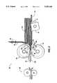
- FIG. 1is a plan view of the sheet separating device of the present invention.
- FIG. 2is an elevational view taken along the line A--A of FIG. 1 in the direction of the arrows;
- FIG. 3is an end view of the sheet separating device of the present invention.
- FIG. 4is a schematic elevational view depicting an illustrative electrophotographic printing machine incorporating the sheet separating apparatus of the present invention therein.
- FIG. 4depicts schematically the various components thereof.
- like reference numeralswill be employed throughout to designate identical elements.
- the apparatus for feeding and separating sheetsis particularly well adapted for use in the electrophotographic printing machine of FIG. 4, it should become evident from the following discussion that it is equally well suited for use in a wide variety of machines and is not necessarily limited in this application to the particular embodiment shown herein.
- FIG. 4Since the practice of electrophotographic printing is well known in the art, the various processing stations for producing a print of document image data are represented in FIG. 4 schematically. Each processing station will be briefly described hereinafter.
- a drum 10 having a photoconductive surface 12 secured to the exterior circumferential surface of a conductive substrateis rotated in the direction of arrow 14 through the various processing stations.
- photoconductive surface 12may be made from selenium.
- a suitable conductive substrateis made from aluminum.
- drum 10rotates a portion of photoconductive surface 12 through charging station A.
- Charging station Aemploys a corona generating device, indicated generally by the reference numeral 16, to charge photoconductive surface 12 to a relatively high, substantially uniform potential.
- Exposure station Bincludes an exposure mechanism, indicated generally by the reference numeral 18, which includes a raster output scanner (ROS) having a suitable source of high intensity light, such as laser, modulated in accordance with the content of the image data as by an acousto-optic modulator to provide zero and first order imaging beams.
- ROSraster output scanner
- the imaging beamis scanned across the photoconductive surface 12 at the exposure station B by a scanning polygon to expose the previously charged photoconductive surface 12 and create a latent electrostatic image or the document represented by the image signals received from an electronic sub-system (ESS) 19.
- ESSelectronic sub-system
- Drum 10rotates the electrostatic latent image recorded on photoconductive surface 12 to development station C.
- Development station Cincludes a developer unit, indicated generally by the reference numeral 20, having a housing with a supply of developer mix contained therein.
- the developer mixcomprises carrier granules with toner particles adhering triboelectrically thereto.
- the carrier granulesare formed from a magnetic material with the toner particles being made from a heat settable plastic.
- Developer unit 20is preferably a magnetic brush development system. A system of this type moves the developer mix through a directional flux field to form a brush thereof.
- the electrostatic latent image recorded on photoconductive surface 12is developed by bringing the brush of developer mix into contact therewith. In this manner, the toner particles are attracted electrostatically from the carrier granules to the latent image forming a toner powder image on photoconductive surface 12.
- a copy sheetis advanced to the printing machine from an auxiliary, module sheet feeding machine, Indicated generally by the reference numeral 120.
- Module sheet feeding machine 120is adapted to be moved to a position adjacent the printing machine sheet inlet, indicated generally by the reference numeral 30.
- the sheet feeding machine 120advances successive copy sheets to the printing machine for processing therein.
- An operatormay readily remove sheet feeding machine 120 and it may be used with another printing machine.
- Sheet feeding machine 120has a sheet feeding apparatus, generally indicated by the reference numeral 60 which advances the copy sheet to the machine inlet 30. Thereafter the copy sheet is advanced along the paper path by drive rolls 34 and 36 to registration roller 24 and idler roller 26.
- the sheet feeding apparatus 60can also be utilized to advance sheets from an internal paper tray 40 to the registration roller 24 in an electrophotographic printing machine.
- Registration roller 24is driven by a motor (not shown)in the direction of arrow 28 and idler roller 26 rotates in the direction of arrow 38 since roller 26 is in contact therewith.
- feed device 60operates to advance the copy sheet from the tray through a guide along a path having rolls 34 and 36 and then into registration roller pairs 24, 26. In this way, the sheet is forwarded to drum 12 in synchronism with the developed image on the drum. The sheet is advanced in the direction of arrow 43 to transfer station D.
- transfer station Dincludes a corona generating device 42 which applies a spray of ions to the back side of the copy sheet. This attracts the toner powder image from photoconductive surface 12 to the copy sheet. After transfer of the toner powder image to the copy sheet, the sheet is advanced by roller pair 44, in the direction of arrow 43, to fusing station E.
- Fusing station Eincludes a fuser assembly indicated generally by the reference numeral 46.
- Fuser assembly 46includes a fuser roll 49 and a backup roll 48 defining a nip therebetween through which the copy sheet passes.
- rollers 52which may be of the same type as registration rollers 24 and 26, to catch tray 54.
- Cleaning station Fincludes a corona generating device (not shown) adapted to neutralize the remaining electrostatic charge on photoconductive surface 12 and that of the residual toner particles.
- the residual toner particles remaining on the photoconductive surface after the transfer operationare removed from the drum 10 by a cleaning blade (not shown)in scrapping contact with the outer periphery of the drum 10 and contained within a cleaning/charging housing.
- a discharge lamp(not shown) floods photoconductive surface 12 with light to dissipate any residual electrostatic charge remaining thereon prior to the charging thereof for the next successive imaging cycle.
- the toner particlesmay be mechanically cleaned from the photoconductive surface by a cleaning brush as is well known in the art.
- the cleaning station F and the charging station Aare contained within the same removable housing.
- FIGS. 1 through 3 inclusivedepict the sheet separating device in greater detail.
- FIG. 1illustrates a plan view of the paper tray and sheet feeding apparatus indicated generally by the reference numeral 60.
- a sheet stack 100 to be fed into the machineis initially placed in the support tray 102.
- the lead edge, 104 of the sheet stack 100rests against the main fang 90 of the sheet feeding apparatus 60.
- the main fang 90is a substantially planar member approximately 70 mm square.
- the main fang 90is mounted so that there is a space of approximately 5 mm between the bottom of the fang finger 91 and the top surface of the sheet support tray 102.
- a nudger 74is located in the bottom of the support tray 102 and in combination with the feed roll 70 provides a transport means between the support tray 102 and the input portion of the electrophotographic printing machine generally indicated by the reference numeral 30.
- the nudger 74is a substantially square cornered roll which rotates and contacts the bottom of the sheet stack 100.
- a ribbed, frictional retard roll 80is located between the support tray 102 and the machine input 30. The retard roll 80 is mounted so that it rests upon the feed roll 70. In operation, the retard roll 80 rotates so that its tangential direction is in the opposite direction of that of the feed roll 70.
- the frictional force exerted on the sheet by the feed roll 70is greater than the tangential frictional force exerted by the retard roll 80 so the sheet is forwarded to the machine input 30. If multiple sheets enter the nip 82 between the retard roll 80 and feed roll 70, the frictional force between the sheets is less than that exerted by the retard roll 80 and only the bottommost sheet, which is driven by the greater frictional force of the feed roll 70 is forwarded to the machine input 30. Any other sheets are held back by the retard roll 80 until they are driven toward the machine input 30 by the greater force of the feed roll 70.
- the corrugated fang 92 of the present inventionis attached to the main fang 90 on the side of the main fang 90, opposite the lead sheet edge 104 of the stack 100.
- the corrugated fang 92extends from the main fang 90 and straddles the retard roll 80.
- the corrugated fang 92is essentially a squared off, J-shaped member which is affixed to the side of the main fang 90 which does not contact the paper stack 100.
- the portion of the corrugated fang 92 which extends below the finger of the main fang 90has stepped ridges formed horizontally across the face of the corrugated fang 92. The fang then extends beyond and straddles the retard roll 80.
- the corrugated fang 92is approximately 50 mm wide. In FIG.
- the entire sheet stack 100initially has the lead edge 104 of the sheets come into contact with the main fang 90.
- the irregular shape of the nudgeralso acts to fluff and separate the sheets on the bottom of the stack 100 as it rotates.
- the main fang 90acts as a queuing device and allows only a small number of sheets 200 from the bottom of the stack 100 to be forwarded toward the machine input 30.
- the lead edges 204, 206,208in turn contact the separating points 94, 96, 98 of the corrugated fang 92, further separating and shingling the group of sheets 200.
- the corrugated fang 92is free to flex upward to a limited extent to avoid wedging of the sheets 200.
- Final sheet separationoccurs as sheets 202, 210 reach the retard roll 80 which, as is explained previously, due to the higher coefficient of friction of the retard roll 80 to a sheet than a sheet to a sheet, prevents all but a single sheet 202 from being forwarded between the retard roll 80 and feed roll 70 to the machine input 30. Each subsequent sheet is separated in a like manner and individually fed to the machine input 30.
- the configuration of the main fang 90can be seen most clearly in FIG. 3.
- the small finger 91 located at the bottom center of the main fang 90 and the resulting clearance between the bottom of the small finger 91 and the sheet support tray 102is clearly illustrated.
- the multiple steps 94, 96, 98 of the corrugated fang 92are shown between the main fang 90 and the retard roll 80.
- the corrugated fang 92is preferably constructed of a nonelastomer, low-coefficient of friction material such as stainless steel, to prevent stubbing of, and damage to, the lead edges of the sheets and to allow each sheet to be forwarded in seriatim as it clears each separation point.
- the separating devicecan be utilized to feed from the bottom of the stack in a recirculating document handler. It is further evident that the device can be adapted to separate the topmost sheet from a stack in a like manner so as to be adaptable to top feeding sheet handling devices.
- a device for feeding individual sheets from the bottom of a sheet stackThe sheet stack is placed in the paper tray with the lead edge abutting the sheet feeding device. The face of the stack rests against the main fang which acts as an initial queuing device. As the nudger forwards the sheets from the bottom of the stack under the main fang, further sheet separation occurs as the lead edges of the sheets strike the separation points of the corrugated fang located between the main fang and the retard roll. The corrugated portion of the fang causes the sheets to be shingled out individually and only a single sheet is allowed to pass under the retard roll and to be fed by the feed roll into the machine.
Landscapes
- Engineering & Computer Science (AREA)
- Mechanical Engineering (AREA)
- Sheets, Magazines, And Separation Thereof (AREA)
Abstract
Description
Claims (11)
Priority Applications (4)
| Application Number | Priority Date | Filing Date | Title |
|---|---|---|---|
| US07/858,262US5350168A (en) | 1992-03-26 | 1992-03-26 | Corrugated fang for multi media feeder |
| JP5036316AJP2572927B2 (en) | 1992-03-26 | 1993-02-25 | Electrostatographic printing equipment |
| DE69306023TDE69306023T2 (en) | 1992-03-26 | 1993-03-23 | Folded clave in a media feeder |
| EP93302185AEP0562812B1 (en) | 1992-03-26 | 1993-03-23 | Corrugated fang for multi media feeder |
Applications Claiming Priority (1)
| Application Number | Priority Date | Filing Date | Title |
|---|---|---|---|
| US07/858,262US5350168A (en) | 1992-03-26 | 1992-03-26 | Corrugated fang for multi media feeder |
Publications (1)
| Publication Number | Publication Date |
|---|---|
| US5350168Atrue US5350168A (en) | 1994-09-27 |
Family
ID=25327898
Family Applications (1)
| Application Number | Title | Priority Date | Filing Date |
|---|---|---|---|
| US07/858,262Expired - Fee RelatedUS5350168A (en) | 1992-03-26 | 1992-03-26 | Corrugated fang for multi media feeder |
Country Status (4)
| Country | Link |
|---|---|
| US (1) | US5350168A (en) |
| EP (1) | EP0562812B1 (en) |
| JP (1) | JP2572927B2 (en) |
| DE (1) | DE69306023T2 (en) |
Cited By (25)
| Publication number | Priority date | Publication date | Assignee | Title |
|---|---|---|---|---|
| US5899451A (en)* | 1994-07-29 | 1999-05-04 | Canon Kabushiki Kaisha | Sheet supply apparatus |
| WO1999028223A1 (en)* | 1997-11-28 | 1999-06-10 | Diebold, Incorporated | Document unstack system for currency recycling automated banking machine |
| US6102389A (en)* | 1996-11-01 | 2000-08-15 | Canon Aptex Kabushiki Kaisha | Sheet feeding device |
| US6263258B1 (en)* | 1998-08-03 | 2001-07-17 | Stanley P. Dabrowski | Scrip dispenser |
| US6322066B1 (en)* | 2000-05-15 | 2001-11-27 | Chern-Bao Rong | Lottery ticket dispensing assembly |
| US6536758B2 (en)* | 1999-05-10 | 2003-03-25 | Fargo Electronics, Inc. | Card hopper |
| US6536759B1 (en)* | 1999-09-30 | 2003-03-25 | Canon Kabushiki Kaisha | Sheet feeding apparatus, image forming apparatus having the sheet feeding apparatus, and image reading apparatus |
| US6550761B1 (en)* | 2001-11-06 | 2003-04-22 | Umax Data Systems Inc. | Integrated paper presser and stopper for automatic paper feeder |
| US20030138279A1 (en)* | 2002-01-24 | 2003-07-24 | Canon Kabushiki Kaisha | Recording apparatus and method for discriminating recording medium type |
| US20030160379A1 (en)* | 2002-02-28 | 2003-08-28 | Canon Denshi Kabushiki Kaisha | Sheet feeding apparatus and image forming apparatus and image reading apparatus provided with same |
| US6758470B1 (en) | 2000-06-27 | 2004-07-06 | Fargo Electronics, Inc. | Card thickness selection gate for a card feeder |
| US20040164478A1 (en)* | 2003-02-24 | 2004-08-26 | Toshiba Tec Kabushiki Kaisha | Sheet conveying device, image forming apparatus and method for conveying sheet |
| US6834794B2 (en) | 2001-08-23 | 2004-12-28 | Stanley P. Dabrowski | Method and apparatus for autonomous validation of issued scrip media |
| US20050003889A1 (en)* | 1998-08-03 | 2005-01-06 | Dabrowski Stanley P. | Method and apparatus for scrip distribution and management permitting redistribution of issued scrip |
| US20050037841A1 (en)* | 2002-09-17 | 2005-02-17 | De Waal Daniel J. | Method and apparatus for providing customizable player bonuses |
| US20060236331A1 (en)* | 2005-02-21 | 2006-10-19 | Kiyoshi Ueda | Image Recording Apparatus |
| US20060290047A1 (en)* | 2005-06-24 | 2006-12-28 | Xerox Corporation | Printing system sheet feeder |
| US20070253037A1 (en)* | 2006-04-28 | 2007-11-01 | Hewlett-Packard Development Company Lp | Separator |
| US20090079125A1 (en)* | 2007-09-26 | 2009-03-26 | Oki Data Corporation | Sheet supply device and image forming apparatus |
| US20110248442A1 (en)* | 2010-04-13 | 2011-10-13 | Yoshiyuki Kato | Banknote processing apparatus |
| US20120300005A1 (en)* | 2008-01-28 | 2012-11-29 | Brother Kogyo Kabushiki Kaisha | Inkjet recording apparatus |
| US20130292405A1 (en)* | 2012-05-04 | 2013-11-07 | Saint-Fun International Ltd. | Card vending machine |
| US9633508B2 (en) | 2003-10-20 | 2017-04-25 | Igt | Enhanced video gaming machine |
| US9898886B2 (en) | 2002-04-19 | 2018-02-20 | Igt | Methods and apparatus for providing communications services at a gaming machine |
| US10839641B2 (en) | 2018-02-27 | 2020-11-17 | Stanley P. Dabrowski | Method and apparatus for modifying gaming machines to provide supplemental or modified functionality |
Families Citing this family (1)
| Publication number | Priority date | Publication date | Assignee | Title |
|---|---|---|---|---|
| CH689671A5 (en)* | 1994-03-07 | 1999-08-13 | Ocd Sa | Sheet feeding device or envelopes to be printed. |
Citations (21)
| Publication number | Priority date | Publication date | Assignee | Title |
|---|---|---|---|---|
| US3469834A (en)* | 1967-04-21 | 1969-09-30 | Xerox Corp | Sheet feeder and separator apparatus |
| US3768803A (en)* | 1972-02-11 | 1973-10-30 | Xerox Corp | Sheet feeder |
| US3895791A (en)* | 1973-03-19 | 1975-07-22 | Xerox Corp | Bottom sheet feeder using separation belt and retard pad |
| US3941373A (en)* | 1974-11-25 | 1976-03-02 | Xerox Corporation | Floating gate sheet separator |
| JPS5233262A (en)* | 1975-09-09 | 1977-03-14 | Nozaki Insatsu Shigyo Kk | Batch leader |
| US4014537A (en)* | 1975-11-28 | 1977-03-29 | Xerox Corporation | Air floatation bottom feeder |
| US4043549A (en)* | 1975-11-24 | 1977-08-23 | Xerox Corporation | Impact feeder |
| JPS5643143A (en)* | 1979-08-27 | 1981-04-21 | Ricoh Co Ltd | Paper feeding apparatus |
| US4327904A (en)* | 1980-05-02 | 1982-05-04 | Xerox Corporation | Electrostatically assisted retard feeder method and apparatus |
| US4368881A (en)* | 1979-06-27 | 1983-01-18 | Savin Corporation | Friction paper feeder |
| US4443006A (en)* | 1980-07-21 | 1984-04-17 | Billcon Corporation Of America | Document and currency counter |
| FR2588537A1 (en)* | 1985-10-14 | 1987-04-17 | Telephonie Ind Commerciale | Friction sheet dispenser, especially for an automatic copier |
| US4718809A (en)* | 1985-03-13 | 1988-01-12 | Smh Alcatel | Device for unstacking flat objects |
| US4770555A (en)* | 1986-04-08 | 1988-09-13 | Societe D'applications Generales D'electricite Et De Mecanique Sagem | Printing machine equipped with a device for the selective supply of sheets from two feed trays |
| JPH0266033A (en)* | 1988-02-24 | 1990-03-06 | Daiwa Seiko Kk | Sheet paper feed method and its device |
| JPH02117528A (en)* | 1988-02-24 | 1990-05-02 | Daiwa Seiko Kk | Paper sheet delivery device |
| JPH02132018A (en)* | 1988-11-09 | 1990-05-21 | Seiko Epson Corp | Cardboard/envelope separation mechanism in paper feeder |
| JPH02178134A (en)* | 1988-12-28 | 1990-07-11 | Nippon Seimitsu Kogyo Kk | Paper feeder |
| US5044622A (en)* | 1987-10-27 | 1991-09-03 | Sadamel Societe Anonyme Des Apparails De Mesure Et De Laboratoire | Apparatus for automatically dispensing objects |
| US5060408A (en)* | 1987-11-21 | 1991-10-29 | Licinvest Ag | Device for the cyclic rearrangement of a pile of sheets |
| US5193795A (en)* | 1987-11-21 | 1993-03-16 | Licinvest Ag | Device for the cyclic rearrangement of a pile of sheets |
Family Cites Families (10)
| Publication number | Priority date | Publication date | Assignee | Title |
|---|---|---|---|---|
| BE795343A (en)* | 1972-02-22 | 1973-05-29 | Pennsylvania Res Ass Inc | SHEET TRAINING, SEPARATION AND STACKING MACHINE |
| JPS5339600Y2 (en)* | 1974-09-28 | 1978-09-26 | ||
| JPS5145209A (en)* | 1974-10-16 | 1976-04-17 | Hitachi Ltd | |
| US3970298A (en)* | 1975-06-05 | 1976-07-20 | Pitney-Bowes, Inc. | Mixed thickness sheet separator and feeder |
| JPS5623720Y2 (en)* | 1975-06-30 | 1981-06-03 | ||
| JPS5632454Y2 (en)* | 1977-09-08 | 1981-08-01 | ||
| US4715593A (en)* | 1985-12-02 | 1987-12-29 | Godlewski Edward S | Stack-supporting bottom feed conveyor |
| JPH0735227B2 (en)* | 1988-11-25 | 1995-04-19 | 三田工業株式会社 | Refeed device |
| US5083765A (en)* | 1990-07-20 | 1992-01-28 | Actmedia, Inc. | Coupon dispenser |
| JPH0488441U (en)* | 1990-12-11 | 1992-07-31 |
- 1992
- 1992-03-26USUS07/858,262patent/US5350168A/ennot_activeExpired - Fee Related
- 1993
- 1993-02-25JPJP5036316Apatent/JP2572927B2/ennot_activeExpired - Fee Related
- 1993-03-23EPEP93302185Apatent/EP0562812B1/ennot_activeExpired - Lifetime
- 1993-03-23DEDE69306023Tpatent/DE69306023T2/ennot_activeExpired - Fee Related
Patent Citations (21)
| Publication number | Priority date | Publication date | Assignee | Title |
|---|---|---|---|---|
| US3469834A (en)* | 1967-04-21 | 1969-09-30 | Xerox Corp | Sheet feeder and separator apparatus |
| US3768803A (en)* | 1972-02-11 | 1973-10-30 | Xerox Corp | Sheet feeder |
| US3895791A (en)* | 1973-03-19 | 1975-07-22 | Xerox Corp | Bottom sheet feeder using separation belt and retard pad |
| US3941373A (en)* | 1974-11-25 | 1976-03-02 | Xerox Corporation | Floating gate sheet separator |
| JPS5233262A (en)* | 1975-09-09 | 1977-03-14 | Nozaki Insatsu Shigyo Kk | Batch leader |
| US4043549A (en)* | 1975-11-24 | 1977-08-23 | Xerox Corporation | Impact feeder |
| US4014537A (en)* | 1975-11-28 | 1977-03-29 | Xerox Corporation | Air floatation bottom feeder |
| US4368881A (en)* | 1979-06-27 | 1983-01-18 | Savin Corporation | Friction paper feeder |
| JPS5643143A (en)* | 1979-08-27 | 1981-04-21 | Ricoh Co Ltd | Paper feeding apparatus |
| US4327904A (en)* | 1980-05-02 | 1982-05-04 | Xerox Corporation | Electrostatically assisted retard feeder method and apparatus |
| US4443006A (en)* | 1980-07-21 | 1984-04-17 | Billcon Corporation Of America | Document and currency counter |
| US4718809A (en)* | 1985-03-13 | 1988-01-12 | Smh Alcatel | Device for unstacking flat objects |
| FR2588537A1 (en)* | 1985-10-14 | 1987-04-17 | Telephonie Ind Commerciale | Friction sheet dispenser, especially for an automatic copier |
| US4770555A (en)* | 1986-04-08 | 1988-09-13 | Societe D'applications Generales D'electricite Et De Mecanique Sagem | Printing machine equipped with a device for the selective supply of sheets from two feed trays |
| US5044622A (en)* | 1987-10-27 | 1991-09-03 | Sadamel Societe Anonyme Des Apparails De Mesure Et De Laboratoire | Apparatus for automatically dispensing objects |
| US5060408A (en)* | 1987-11-21 | 1991-10-29 | Licinvest Ag | Device for the cyclic rearrangement of a pile of sheets |
| US5193795A (en)* | 1987-11-21 | 1993-03-16 | Licinvest Ag | Device for the cyclic rearrangement of a pile of sheets |
| JPH0266033A (en)* | 1988-02-24 | 1990-03-06 | Daiwa Seiko Kk | Sheet paper feed method and its device |
| JPH02117528A (en)* | 1988-02-24 | 1990-05-02 | Daiwa Seiko Kk | Paper sheet delivery device |
| JPH02132018A (en)* | 1988-11-09 | 1990-05-21 | Seiko Epson Corp | Cardboard/envelope separation mechanism in paper feeder |
| JPH02178134A (en)* | 1988-12-28 | 1990-07-11 | Nippon Seimitsu Kogyo Kk | Paper feeder |
Non-Patent Citations (6)
| Title |
|---|
| Xerox Disclosure Journal, vol. 12, No. 1, Jan./Feb. 1987, p. 51, "Bottom Friction Retard Feeder", William D. Milillo. |
| Xerox Disclosure Journal, vol. 12, No. 1, Jan./Feb. 1987, p. 51, Bottom Friction Retard Feeder , William D. Milillo.* |
| Xerox Disclosure Journal, vol. 7, No. 2, Mar./Apr. 1982, pp. 67 68, Floating Gate Sheet Separator/Feeder with Outriggers , Dennis P. teeter, et al.* |
| Xerox Disclosure Journal, vol. 7, No. 2, Mar./Apr. 1982, pp. 67-68, "Floating Gate Sheet Separator/Feeder with Outriggers", Dennis P. teeter, et al. |
| Xerox Disclosure Journal, vol. 8, No. 4, Jul./Aug. 1983, "Edge Force Sheet Separating System", John Maksymiak, et al. pp. 315-316. |
| Xerox Disclosure Journal, vol. 8, No. 4, Jul./Aug. 1983, Edge Force Sheet Separating System , John Maksymiak, et al. pp. 315 316.* |
Cited By (52)
| Publication number | Priority date | Publication date | Assignee | Title |
|---|---|---|---|---|
| US5899451A (en)* | 1994-07-29 | 1999-05-04 | Canon Kabushiki Kaisha | Sheet supply apparatus |
| US6102389A (en)* | 1996-11-01 | 2000-08-15 | Canon Aptex Kabushiki Kaisha | Sheet feeding device |
| CN1086993C (en)* | 1997-11-28 | 2002-07-03 | 迪布尔特有限公司 | File removal system for currency recycling automated banking machine and method of operation thereof |
| WO1999028223A1 (en)* | 1997-11-28 | 1999-06-10 | Diebold, Incorporated | Document unstack system for currency recycling automated banking machine |
| US9905075B2 (en) | 1998-08-03 | 2018-02-27 | Western Gaming Properties | Method and apparatus for modifying gaming machines to provide supplemental or modified functionality |
| US8133102B2 (en) | 1998-08-03 | 2012-03-13 | Dabrowski Stanley P | Method and apparatus for modifying gaming machines to provide supplemental or modified functionality |
| US8388424B2 (en) | 1998-08-03 | 2013-03-05 | Stanley P. Dabrowski | Method and apparatus for modifying gaming machines to provide supplemental or modified functionality |
| US9022847B2 (en) | 1998-08-03 | 2015-05-05 | Western Gaming Properties | Method and apparatus for modifying gaming machines to provide supplemental or modified functionality |
| US7520810B2 (en) | 1998-08-03 | 2009-04-21 | Dabrowski Stanley P | Method and apparatus for scrip distribution and management permitting redistribution of issued scrip |
| US9437075B2 (en) | 1998-08-03 | 2016-09-06 | Western Gaming Properties | Method and apparatus for modifying gaming machines to provide supplemental or modified functionality |
| US20090054135A1 (en)* | 1998-08-03 | 2009-02-26 | Dabrowski Stanley P | Method and apparatus for modifying gaming machines to provide supplemental or modified functionality |
| US8734213B2 (en) | 1998-08-03 | 2014-05-27 | Western Gaming Properties | Method and apparatus for modifying gaming machines to provide supplemental or modified functionality |
| US9437076B2 (en) | 1998-08-03 | 2016-09-06 | Western Gaming Properties | Method and apparatus for modifying gaming machines to provide supplemental or modified functionality |
| US8968066B2 (en)* | 1998-08-03 | 2015-03-03 | Western Gaming Properties | Method and apparatus for modifying gaming machines to provide supplemental or modified functionality |
| US9177436B2 (en) | 1998-08-03 | 2015-11-03 | Western Gaming Properties | Method and apparatus for modifying gaming machines to provide supplemental or modified functionality |
| US6263258B1 (en)* | 1998-08-03 | 2001-07-17 | Stanley P. Dabrowski | Scrip dispenser |
| US20050003889A1 (en)* | 1998-08-03 | 2005-01-06 | Dabrowski Stanley P. | Method and apparatus for scrip distribution and management permitting redistribution of issued scrip |
| US6536758B2 (en)* | 1999-05-10 | 2003-03-25 | Fargo Electronics, Inc. | Card hopper |
| US6536759B1 (en)* | 1999-09-30 | 2003-03-25 | Canon Kabushiki Kaisha | Sheet feeding apparatus, image forming apparatus having the sheet feeding apparatus, and image reading apparatus |
| US6322066B1 (en)* | 2000-05-15 | 2001-11-27 | Chern-Bao Rong | Lottery ticket dispensing assembly |
| US6758470B1 (en) | 2000-06-27 | 2004-07-06 | Fargo Electronics, Inc. | Card thickness selection gate for a card feeder |
| US20050096127A1 (en)* | 2001-08-23 | 2005-05-05 | Dabrowski Stanley P. | Method and apparatus for autonomous validation of issued scrip media |
| US7036721B2 (en) | 2001-08-23 | 2006-05-02 | Dabrowski Stanley P | Method and apparatus for autonomous validation of issued scrip media |
| US6834794B2 (en) | 2001-08-23 | 2004-12-28 | Stanley P. Dabrowski | Method and apparatus for autonomous validation of issued scrip media |
| WO2003029117A3 (en)* | 2001-09-28 | 2003-07-24 | Fargo Electronics Inc | Card hopper |
| US6550761B1 (en)* | 2001-11-06 | 2003-04-22 | Umax Data Systems Inc. | Integrated paper presser and stopper for automatic paper feeder |
| US6830398B2 (en)* | 2002-01-24 | 2004-12-14 | Canon Kabushiki Kaisha | Recording apparatus and method for discriminating recording medium type |
| US20030138279A1 (en)* | 2002-01-24 | 2003-07-24 | Canon Kabushiki Kaisha | Recording apparatus and method for discriminating recording medium type |
| US6869070B2 (en)* | 2002-02-28 | 2005-03-22 | Canon Kabushiki Kaisha | Sheet feeding apparatus and image forming apparatus and image reading apparatus provided with same |
| US20030160379A1 (en)* | 2002-02-28 | 2003-08-28 | Canon Denshi Kabushiki Kaisha | Sheet feeding apparatus and image forming apparatus and image reading apparatus provided with same |
| US9898886B2 (en) | 2002-04-19 | 2018-02-20 | Igt | Methods and apparatus for providing communications services at a gaming machine |
| US20050037841A1 (en)* | 2002-09-17 | 2005-02-17 | De Waal Daniel J. | Method and apparatus for providing customizable player bonuses |
| US7766744B2 (en) | 2002-09-17 | 2010-08-03 | Igt | Method and apparatus for providing customizable player bonuses |
| US6932337B2 (en)* | 2003-02-24 | 2005-08-23 | Kabushiki Kaisha Toshiba | Sheet conveying device, image forming apparatus and method for conveying sheet |
| US7427060B2 (en) | 2003-02-24 | 2008-09-23 | Kabushiki Kaisha Toshiba | Sheet conveying device, image forming apparatus and method for conveying sheet |
| US20050258587A1 (en)* | 2003-02-24 | 2005-11-24 | Kabushiki Kaisha Toshiba | Sheet conveying device, image forming apparatus and method for conveying sheet |
| US20040164478A1 (en)* | 2003-02-24 | 2004-08-26 | Toshiba Tec Kabushiki Kaisha | Sheet conveying device, image forming apparatus and method for conveying sheet |
| US9633508B2 (en) | 2003-10-20 | 2017-04-25 | Igt | Enhanced video gaming machine |
| US7484725B2 (en)* | 2005-02-21 | 2009-02-03 | Brother Kogyo Kabushiki Kaisha | Image recording apparatus |
| US20060236331A1 (en)* | 2005-02-21 | 2006-10-19 | Kiyoshi Ueda | Image Recording Apparatus |
| US7387297B2 (en)* | 2005-06-24 | 2008-06-17 | Xerox Corporation | Printing system sheet feeder using rear and front nudger rolls |
| US20060290047A1 (en)* | 2005-06-24 | 2006-12-28 | Xerox Corporation | Printing system sheet feeder |
| US7852526B2 (en)* | 2006-04-28 | 2010-12-14 | Hewlett-Packard Development Company, L.P. | Separator |
| US20070253037A1 (en)* | 2006-04-28 | 2007-11-01 | Hewlett-Packard Development Company Lp | Separator |
| US8770575B2 (en)* | 2007-09-26 | 2014-07-08 | Oki Data Corporation | Sheet supply device and image forming apparatus |
| US20090079125A1 (en)* | 2007-09-26 | 2009-03-26 | Oki Data Corporation | Sheet supply device and image forming apparatus |
| US8628192B2 (en)* | 2008-01-28 | 2014-01-14 | Brother Kogyo Kabushiki Kaisha | Inkjet recording apparatus |
| US20120300005A1 (en)* | 2008-01-28 | 2012-11-29 | Brother Kogyo Kabushiki Kaisha | Inkjet recording apparatus |
| US8302960B2 (en)* | 2010-04-13 | 2012-11-06 | Laurel Precision Machines Co., Ltd. | Banknote processing apparatus with separating and feeding portion |
| US20110248442A1 (en)* | 2010-04-13 | 2011-10-13 | Yoshiyuki Kato | Banknote processing apparatus |
| US20130292405A1 (en)* | 2012-05-04 | 2013-11-07 | Saint-Fun International Ltd. | Card vending machine |
| US10839641B2 (en) | 2018-02-27 | 2020-11-17 | Stanley P. Dabrowski | Method and apparatus for modifying gaming machines to provide supplemental or modified functionality |
Also Published As
| Publication number | Publication date |
|---|---|
| DE69306023T2 (en) | 1997-04-03 |
| EP0562812A1 (en) | 1993-09-29 |
| JP2572927B2 (en) | 1997-01-16 |
| JPH061479A (en) | 1994-01-11 |
| EP0562812B1 (en) | 1996-11-20 |
| DE69306023D1 (en) | 1997-01-02 |
Similar Documents
| Publication | Publication Date | Title |
|---|---|---|
| US5350168A (en) | Corrugated fang for multi media feeder | |
| US4591259A (en) | Tri-pass baffle decurler | |
| US5555083A (en) | Decurler apparatus for reducing cross curl in sheets | |
| US4744555A (en) | Sheet transport and registration apparatus | |
| US5211388A (en) | Retard roll enhancement | |
| US4381860A (en) | Paddle wheel retard feeder | |
| US4632533A (en) | Off-set nip roll decurler | |
| US5657983A (en) | Wear resistant registration edge guide | |
| US5149077A (en) | Hybrid nudger roll | |
| US5346199A (en) | Adjustable nudger roll normal force using multiple springs | |
| US5967507A (en) | Automatic document handler having non-relative motion vacuum corrugating device | |
| US3861670A (en) | Sheet feeding apparatus | |
| US4364550A (en) | Corrugation venturi paper feeder | |
| US4984778A (en) | Sheet feeder with skew control | |
| EP0425249B1 (en) | Copiers with side-registration systems | |
| US5967511A (en) | Sheet registration assembly including a force reducing deskew roll | |
| US4515357A (en) | Paddle retard feeder | |
| USRE33843E (en) | Sheet transport and registration apparatus | |
| EP0047139B1 (en) | Sheet feeding apparatus | |
| US5348282A (en) | Self adjusting feed roll | |
| CA1202042A (en) | Sheet feeding and separating apparatus employing a multiple piece entrance guide | |
| US5156392A (en) | Moving edge side registration device | |
| JPH0356475B2 (en) | ||
| CA2126590C (en) | Retard feed apparatus with noise suppression device | |
| JPS60200273A (en) | Separating and conveying device for transfer paper |
Legal Events
| Date | Code | Title | Description |
|---|---|---|---|
| AS | Assignment | Owner name:XEROX CORPORATION A CORP. OF NEW YORK, CONNECTI Free format text:ASSIGNMENT OF ASSIGNORS INTEREST.;ASSIGNOR:SHERIDAN, KEVIN M.;REEL/FRAME:006069/0355 Effective date:19920325 | |
| FPAY | Fee payment | Year of fee payment:4 | |
| FPAY | Fee payment | Year of fee payment:8 | |
| AS | Assignment | Owner name:BANK ONE, NA, AS ADMINISTRATIVE AGENT, ILLINOIS Free format text:SECURITY INTEREST;ASSIGNOR:XEROX CORPORATION;REEL/FRAME:013153/0001 Effective date:20020621 | |
| AS | Assignment | Owner name:JPMORGAN CHASE BANK, AS COLLATERAL AGENT, TEXAS Free format text:SECURITY AGREEMENT;ASSIGNOR:XEROX CORPORATION;REEL/FRAME:015134/0476 Effective date:20030625 Owner name:JPMORGAN CHASE BANK, AS COLLATERAL AGENT,TEXAS Free format text:SECURITY AGREEMENT;ASSIGNOR:XEROX CORPORATION;REEL/FRAME:015134/0476 Effective date:20030625 | |
| REMI | Maintenance fee reminder mailed | ||
| LAPS | Lapse for failure to pay maintenance fees | ||
| STCH | Information on status: patent discontinuation | Free format text:PATENT EXPIRED DUE TO NONPAYMENT OF MAINTENANCE FEES UNDER 37 CFR 1.362 | |
| FP | Lapsed due to failure to pay maintenance fee | Effective date:20060927 | |
| AS | Assignment | Owner name:XEROX CORPORATION, CONNECTICUT Free format text:RELEASE BY SECURED PARTY;ASSIGNOR:JPMORGAN CHASE BANK, N.A. AS SUCCESSOR-IN-INTEREST ADMINISTRATIVE AGENT AND COLLATERAL AGENT TO JPMORGAN CHASE BANK;REEL/FRAME:066728/0193 Effective date:20220822 |