US5349984A - Check valve - Google Patents
Check valveDownload PDFInfo
- Publication number
- US5349984A US5349984AUS08/008,452US845293AUS5349984AUS 5349984 AUS5349984 AUS 5349984AUS 845293 AUS845293 AUS 845293AUS 5349984 AUS5349984 AUS 5349984A
- Authority
- US
- United States
- Prior art keywords
- valve
- valve element
- plug
- axial passageway
- compression spring
- Prior art date
- Legal status (The legal status is an assumption and is not a legal conclusion. Google has not performed a legal analysis and makes no representation as to the accuracy of the status listed.)
- Expired - Lifetime
Links
- 230000006835compressionEffects0.000claimsabstractdescription38
- 238000007906compressionMethods0.000claimsabstractdescription38
- 239000012530fluidSubstances0.000claimsdescription17
- 230000002829reductive effectEffects0.000claimsdescription7
- 239000002184metalSubstances0.000claims1
- 238000005336crackingMethods0.000abstractdescription14
- 239000012858resilient materialSubstances0.000description13
- 239000000463materialSubstances0.000description12
- 230000036961partial effectEffects0.000description10
- 238000003780insertionMethods0.000description7
- 230000037431insertionEffects0.000description7
- 238000004519manufacturing processMethods0.000description5
- 238000007789sealingMethods0.000description5
- 238000000465mouldingMethods0.000description4
- 238000010276constructionMethods0.000description3
- 230000003247decreasing effectEffects0.000description3
- 230000000717retained effectEffects0.000description2
- 229920002725thermoplastic elastomerPolymers0.000description2
- 244000043261Hevea brasiliensisSpecies0.000description1
- 238000007551Shore hardness testMethods0.000description1
- 230000001419dependent effectEffects0.000description1
- 230000002401inhibitory effectEffects0.000description1
- 238000002347injectionMethods0.000description1
- 239000007924injectionSubstances0.000description1
- 238000002156mixingMethods0.000description1
- 229920003052natural elastomerPolymers0.000description1
- 229920001194natural rubberPolymers0.000description1
- 239000004033plasticSubstances0.000description1
- 229920001296polysiloxanePolymers0.000description1
- 239000012815thermoplastic materialSubstances0.000description1
Images


Classifications
- F—MECHANICAL ENGINEERING; LIGHTING; HEATING; WEAPONS; BLASTING
- F16—ENGINEERING ELEMENTS AND UNITS; GENERAL MEASURES FOR PRODUCING AND MAINTAINING EFFECTIVE FUNCTIONING OF MACHINES OR INSTALLATIONS; THERMAL INSULATION IN GENERAL
- F16K—VALVES; TAPS; COCKS; ACTUATING-FLOATS; DEVICES FOR VENTING OR AERATING
- F16K15/00—Check valves
- F16K15/02—Check valves with guided rigid valve members
- F16K15/025—Check valves with guided rigid valve members the valve being loaded by a spring
- F16K15/026—Check valves with guided rigid valve members the valve being loaded by a spring the valve member being a movable body around which the medium flows when the valve is open
- F—MECHANICAL ENGINEERING; LIGHTING; HEATING; WEAPONS; BLASTING
- F16—ENGINEERING ELEMENTS AND UNITS; GENERAL MEASURES FOR PRODUCING AND MAINTAINING EFFECTIVE FUNCTIONING OF MACHINES OR INSTALLATIONS; THERMAL INSULATION IN GENERAL
- F16K—VALVES; TAPS; COCKS; ACTUATING-FLOATS; DEVICES FOR VENTING OR AERATING
- F16K15/00—Check valves
- F16K15/02—Check valves with guided rigid valve members
- F16K15/06—Check valves with guided rigid valve members with guided stems
- F16K15/063—Check valves with guided rigid valve members with guided stems the valve being loaded by a spring
- F16K15/065—Check valves with guided rigid valve members with guided stems the valve being loaded by a spring spring pulling the closure member against the seat
- F—MECHANICAL ENGINEERING; LIGHTING; HEATING; WEAPONS; BLASTING
- F16—ENGINEERING ELEMENTS AND UNITS; GENERAL MEASURES FOR PRODUCING AND MAINTAINING EFFECTIVE FUNCTIONING OF MACHINES OR INSTALLATIONS; THERMAL INSULATION IN GENERAL
- F16K—VALVES; TAPS; COCKS; ACTUATING-FLOATS; DEVICES FOR VENTING OR AERATING
- F16K27/00—Construction of housing; Use of materials therefor
- F16K27/02—Construction of housing; Use of materials therefor of lift valves
- F16K27/0209—Check valves or pivoted valves
- Y—GENERAL TAGGING OF NEW TECHNOLOGICAL DEVELOPMENTS; GENERAL TAGGING OF CROSS-SECTIONAL TECHNOLOGIES SPANNING OVER SEVERAL SECTIONS OF THE IPC; TECHNICAL SUBJECTS COVERED BY FORMER USPC CROSS-REFERENCE ART COLLECTIONS [XRACs] AND DIGESTS
- Y10—TECHNICAL SUBJECTS COVERED BY FORMER USPC
- Y10T—TECHNICAL SUBJECTS COVERED BY FORMER US CLASSIFICATION
- Y10T137/00—Fluid handling
- Y10T137/7722—Line condition change responsive valves
- Y10T137/7837—Direct response valves [i.e., check valve type]
- Y10T137/7904—Reciprocating valves
- Y10T137/7922—Spring biased
- Y10T137/7929—Spring coaxial with valve
- Y10T137/7936—Spring guides valve head
- Y—GENERAL TAGGING OF NEW TECHNOLOGICAL DEVELOPMENTS; GENERAL TAGGING OF CROSS-SECTIONAL TECHNOLOGIES SPANNING OVER SEVERAL SECTIONS OF THE IPC; TECHNICAL SUBJECTS COVERED BY FORMER USPC CROSS-REFERENCE ART COLLECTIONS [XRACs] AND DIGESTS
- Y10—TECHNICAL SUBJECTS COVERED BY FORMER USPC
- Y10T—TECHNICAL SUBJECTS COVERED BY FORMER US CLASSIFICATION
- Y10T137/00—Fluid handling
- Y10T137/7722—Line condition change responsive valves
- Y10T137/7837—Direct response valves [i.e., check valve type]
- Y10T137/7904—Reciprocating valves
- Y10T137/7922—Spring biased
- Y10T137/7929—Spring coaxial with valve
- Y10T137/7938—Guide means integral and coplanar with valve disk
Definitions
- This inventionrelates to check valves. More particularly, this invention relates to check valves having a pre-set cracking pressure.
- check valvesdesigned to control the one-way flow of a fluid therethrough. More particularly, one predominant type of check valve comprises a ball reciprocatingly positioned within a caged area of a fluid passageway. The flow of fluid in one direction through the passageway is uninhibited (unchecked) as it flows around the ball to exit the passageway. However, in the opposite direction, the flow of fluid forces the ball against a valve seat, thereby inhibiting (checking) the flow of fluid therethrough.
- check valvesMany variations of this basic embodiment of a check valve have been developed over the past many decades that check valves have been in use, each having certain advantages when used in certain applications.
- check valvesIn one application area, check valves, commonly referred to as "catheter” check valves, have been developed to control the one-way flow of a fluid into an inflatable bulb of a catheter or endotracheal tube or in similar relatively low-pressure applications. Indeed, due to the relatively low back pressure exerted on the valve element to urge it against the valve seat, it is usually desirable to provide means for constantly urging the valve element against the valve seat such that the valve remains closed when little or no back pressure is present. Consequently, check valves of this nature have a pre-set cracking pressure which must be exerted on the valve element to unseat itself from the valve seat allowing the flow of the fluid in the unchecked direction,
- U.S. Pat. No. 3,831,629discloses a check valve comprising a valve element which is constantly urged in sealing engagement with a valve seat thereby maintaining the valve in a closed condition even during the complete absence of back pressure exerted on the valve. Moreover, a certain amount of forward cracking pressure must be exerted on the valve element in the unchecked direction to unseat the valve element, allowing the flow of fluid therethrough. As illustrated and discussed in said patent, such positive cracking pressure may be overcome by means of a mechanical instrument, such as a syringe, by fluid pressure, or by combination of the same.
- valve elementmay comprise a substantially cylindrical-wall configuration (FIG. 5), a three point star-configuration (FIGS. 6 and 7), or a bellows configuration (FIG. 8).
- FIGS. 5-8 of U.S. 3,831,629it is seen that the valve element may comprise a substantially cylindrical-wall configuration (FIG. 5), a three point star-configuration (FIGS. 6 and 7), or a bellows configuration (FIG. 8).
- a similar star-configuration of a valve elementis illustrated in U.S. Pat. No. 4,429,856.
- a similar valve element having a bellows configurationis disclosed in U.S. Pat. No. 3,385,301.
- valve elementhaving an elongated stem composed of a resilient, porous-form plastic material.
- a valve elementhaving an elongated stem composed of a resilient, porous-form plastic material.
- this inventioncomprises various embodiments of improved check valves having presettable cracking pressures.
- the improved check valvesemploy spring-loaded valve elements.
- the valve element and the compression springare held into position in the valve body by means of an apertured plug.
- the need for an apertured plugis eliminated by capturing the compression spring between a protuberance on the inside of the valve body and a snap ring positioned about the valve element. The use of a compression spring in these embodiments assure that the cracking pressure necessary to open the check valve is very accurately predetermined for a given back pressure.
- the valve bodyincludes an input composed of a resilient material which forms a better seal with the tip of a medical syringe or other instrument.
- the tapered portion of the inputresiliently forms about the tip of a medical syringe as the medical syringe is inserted further and further at their end.
- a sealis therefore formed about a substantial portion of the outer surface of the tip of the syringe, irrespective of the variations in the types of tips and/or the manufacturing tolerances of the tips.
- the check valve of this inventioncomprises a valve element having a star-shaped configuration with rounded tips, rather than the square tips illustrated in U.S. Pat. No. 3,831,629. Coupled with flutes positioned on the lumen of the axial passageway of the valve body, the round tips of the star-shaped valve element assures that the element will not lodge when the deformed in use and then be jammed in place when the syringe tip is removed.
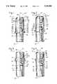
- FIG. 1is a partial cross-sectional view of one embodiment of the check valve of the invention comprising a valve element operatively positioned within a valve body by means of a compression spring and apertured plug, wherein the valve body includes a contoured output for easy insertion within a tube and an input end for receiving the tip of a medical syringe;
- FIG. 2is a partial cross-sectional view of another embodiment of the check valve of the invention comprising a valve element operatively positioned within a valve body by means of a compression spring and apertured plug, wherein the valve body includes a contoured output end for easy insertion within a tube and an input end including a standard female luer lock fitting for receiving a conventional medical syringe having a corresponding male luer lock fitting about its tip;
- FIG. 3is a partial cross-sectional view of another embodiment of the check valve of the invention comprising a valve element operatively positioned within a valve body by means of a compression spring and apertured plug, wherein the valve body comprises a rearwardly sloping annular ring that permits the valve to be inserted into a tube and not easily removed therefrom;
- FIG. 4is a partial cross-sectional view of another embodiment of a check valve of the invention comprising a valve element operatively positioned within a valve body by means of a compression spring and an apertured plug, wherein the valve body includes a forwardly sloping annular ring which facilitates a snap-on clamping sleeve as shown in U.S. Pat. No. 4,776,369;
- FIG. 5is a partial cross-sectional view of another embodiment of a check valve of the invention comprising a valve element operatively positioned within a valve body by means of a compression spring and an apertured plug, wherein the annular ring of the embodiment shown in FIGS. 3 and 4 may be of a slightly increased diameter and may comprise a roughened surface to form a better seal with the lumen of the tube in which it is inserted;
- FIG. 6is a partial cross-sectional view of another embodiment of the check valve of the invention comprising a valve element operatively positioned within a valve body by means of a compression spring and an apertured plug, wherein the apertured plug is asymmetrical and includes a sloped, bullet-shaped configuration to facilitate insertion within a tube;
- FIG. 7is a cross-sectional view and FIG. 7A is an input end view of another embodiment of the check valve of the invention comprising an elongated valve element operatively positioned within a valve body by means of a compression spring and an apertured plug, wherein the valve element comprises an annular disk-shaped ring on which is seated an annular gasket and wherein the apertured plug comprises a bullet-shaped annular ring having depending legs which extend into the output of the axial passageway of the valve body;
- FIG. 8is a partial cross-sectional view of another embodiment of the check valve of the invention comprising an elongated valve element operatively positioned within a valve body by means of a compression spring and a snap ring, wherein the snap ring snaps onto the input end of the elongated valve body to capture the compression spring between the snap ring and an annular protrusion extending within the valve body;
- FIGS. 9-13are partial cross-sectional views of various embodiments of an improved valve body, wherein the input of the valve body is composed of a resilient material which accommodates a variety of sizes of syringe tips and/or variances in manufacturing tolerances to thereby form a better seal with the tip of the medical syringe when inserted therein;
- FIG. 9illustrating the valve body molded by two component molding
- FIGS. 10 and 11illustrating the input and the output being molded separately and then snapped together
- FIGS. 12 and 13A and 13Billustrating the valve body being molded entirely of the resilient material and including an outer sleeve composed of a rigid material positioned over the output of the valve body for adding rigidity to the valve body;
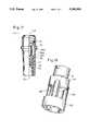
- FIG. 14is a partial cross-sectional view of a star-shaped valve element and apertured plug
- FIG. 14Ais an end view of the apertured plug illustrating the apertures in the plug
- FIGS. 15 and 16are end views of the star-shaped valve element positioned within the valve body illustrating the rounded tips of the points of the star-shaped valve element and their position with respect to the flutes positioned within the valve body;
- FIG. 17is a partial cross-sectional view of another embodiment of a check valve of the invention comprising a valve element operatively positioned within a valve body by means of an apertured plug, wherein the valve element comprises a narrowed diameter to reduce the possibility of the valve element being lodged within the axial passageway of the valve body;
- FIG. 18is a perspective view of a leg-shaped valve element comprising a plurality of legs which extend from the valve element and which are joined at an annular ring;
- FIG. 19is a cross-sectional view of FIG. 18 coupled with an apertured plug.
- the present inventioncomprises many new embodiments of check valves having various features which satisfy the particular needs in the industry.
- the following descriptionbroadly categorizes the check valves according to their respective features.
- the check valve 10 of the inventioncomprises a valve body 14 comprising a sleeve-like integral configuration with a central axial passageway 20 therethrough defining input 22 and output 24.
- a valve element 12is reciprocatably positioned within passageway 20 to check the flow of fluid therethrough from its input 22 to its output 24.
- FIGS. 1-7illustrate an improved check valve 10 of the invention which employs valve element 12 operatively positioned within a valve body 15 by means of a compression spring 16 and an apertured plug 18.
- the valve element 12comprises a reduced diameter portion 26 and an increased diameter portion 28 joined together at a forwardly converging frustro-conical valve seat 30.
- the lumen of the axial passageway 20comprises a reduced diameter portion 32 and an increased diameter portion 34 joined together at a forwardly converging frustro-conical valve seat 36.
- Valve element 12is positioned within the axial passageway 20 such that its valve seat 30 is matable against the valve seat 36 of the body 14 to create an airtight seal therebetween.
- valve element 12 and the compression spring 16are retained in position within the axial passageway 20 by means of a symmetrical plug 38.
- plug 38comprises a symmetrical design such that the plug 38 can be inserted into the passageway 20 without concern for proper orientation during assembly.
- the symmetrical plug 38comprises an annular ring 40 which is engageable within a corresponding annular slot 42 formed within the lumen of the sleeve-like valve body 14.
- a pair of diametrical vanes 44 and 46are integrally formed within the annular ring 40 such that fluid flowing through the passageway 20 flows through the four quadrants or apertures defined by the respective vanes 44 and 46 and the annular ring 40.
- Each of the vanes 44 and 46comprise a lower annular platform portion 48 and an upper annular platform portion 50 joined at sloping edge 52.
- the lower corner 54 formed between the sloping edge 52 and the lower platform portion 48is formed at a diameter substantially equal to the inside diameter of the compression spring 16.
- the valve element 12comprises, at its rearward end, a lower and upper platform positions 56 and 58 joined at the sloping edge 60.
- the lower corner 62 formed between the sloping edge 60 and the lower platform portion 56is formed at a diameter substantially equal to the inside diameter of the compression spring 16 so as to centrally locate the forward end of the compression spring 16 within the axial passageway 20.
- the compression spring 16may be diametrically tapered inwardly or outwardly along its length. In such applications, the diameters defined by corners 54 and 62 of the plug 38 and the valve element 12 should be correspondingly increased or decreased.
- each of these embodiments of the check valve 10 of the inventionare assembled by simply inserting the valve element 12 into the axial passageway 20, inserting the compression spring 16 into the axial passageway 20, and then snapping into place the symmetrical plug 38 into the axial passageway 20 until the plug's annular ring 40 engages into the annular slot 42.
- the spring tension of the compression spring 68determines the amount of cracking pressure necessary to open the valve 10.
- the compression spring 16comprises a linearly constant spring tension; however, without departing from the spirit and scope of this invention, compression spring 16 may comprise increasing or decreasing spring tensions dependent upon the degree in which the compression spring 16 is compressed,
- FIGS. 1 and 2The specific embodiment of the check valve 10 of the invention illustrated in FIGS. 1 and 2 comprises a contoured output end 64 for easily receiving a tube thereabout. It is noted that a flanged mounting extending from the outside of the valve body 10, as shown in FIG. 2 of U.S. Pat. No. 4,681,132, may be provided for gripping about the tube after insertion therein. A stop ring 66 may be annularly formed about the valve body 14 to properly locate the tube along the length of the body 14.
- the input 22 of the axial passageway 20may be configured in a step configuration as shown in FIG. 1 for sealingly receiving the tip of a conventional medical syringe.
- the outside of the valve body 14may include a standard female luer lock fitting 70 for receiving a conventional medical syringe having a corresponding male luer lock fitting about its tip.
- the outside of the valve body 14may include a rearwardly sloping annular ring 72 or a forwardly sloping annular ring 74, respectively.
- the rearwardly sloping annular ring 72 of FIG. 3permits the valve 10 to be inserted into a tube so that fluid may flow into the tube, but fluid flow from the tube is checked.
- the sharp corner 76 of the annular ring 72prevents the valve 10 from being removed from the tube.
- the forwardly sloping annular ring 74 of FIG. 4facilitates a snap-on clamping sleeve as shown in U.S. Pat. No. 4,776,369, the disclosure of which is hereby incorporated by reference herein.
- the cylindrical portion 78 of the annular rings 72 and 74may be of a slightly increased diameter so as to form an additional corner 80. Also, the cylindrical portion 78 may comprise a roughened surface 82 to form a better seal with the lumen of the tube.
- the apertured plug 18comprises an asymmetrical plug 84, similar in construction to the symmetrical plug 38, having perpendicularly disposed vanes 44 and 46 integrally formed with the annular ring 40.
- vanes 44 and 46comprise a sloped, bullet-shaped configuration 86 which facilitates insertion within a tube.
- the bullet-shaped configuration 86may be of a slightly increased diameter relative to the diameter of the valve body 14 so as to define a sharp corner 88 at each of the vanes 44 and 46. The sharp corners 88 preclude removal of the valve 10 after insertion within a tube.
- valve element 12comprises an elongated configuration 90 having a cross cross-sectional configuration as illustrated in FIG. 7A.
- An annular disk-shaped ring 92is formed integrally with the elongated configuration of the valve element 90 and includes a diameter which is appreciably greater than the diameter of the elongated configuration 90 of the valve element so as to define a platform 94 on which is seated an annular gasket 96.
- the axial passageway 20 of the valve body 40comprises a reduced diameter portion 98 of a diameter only appreciably greater than the diameter of the elongated configuration 90 of the valve element 12.
- the reduced diameter portion 98comprises inwardly extending annular valve seat 100 for sealing engagement with gasket 96.
- the annular valve seat 100preferably comprises sloping side walls 102 to assure that an adequate seal with gasket 96 is formed even after considerable wear.
- apertured plug 18comprises a bullet-shaped annular ring 104 having depending legs 106 which extend into the output 24 of the axial passageway 20.
- each of the legs 106includes an outwardly extending protrusion 108 which resiliently engage into a corresponding annular groove 110 formed on the lumen of the output 24 of the axial passageway.
- the apertured plug 18 in this embodimentincludes hole 112 which is of sufficient size to permit the elongated configuration 90 of the valve element 12 to extend therethrough.
- the diameter of hole 112is sufficiently small so as to retain the compression spring 16 against its undersurface 114.
- the annular ring 92 of the elongated configuration 90 of the valve element 12is of sufficient diameter to define platform 116 on the side opposite to the gasket platform 94, which is appreciably greater than the diameter of the compression spring 16.
- the compression spring 16is captured between the plug 18 and the annular ring 92 in such a manner that the gasket 96 is resiliently urged into sealing engagement with the annular valve seat 100 of the valve body 14.
- the valve element 12comprises an elongated configuration 90 having a fluted cross-sectional configuration similar to that illustrated in FIG. 7A.
- the rearward end of the elongated configuration 90comprises a forwardly converging frustro-conical valve seat 118 blending into an increased diameter portion 120.
- the valve body 14includes a reduced diameter portion 98 similar to that shown in FIG. 7, but including a gasket platform 122 in lieu of the annular valve seat 100.
- An annular gasket 124is positioned on the gasket platform 122. As shown, gasket 124 includes an inner sharp corner 126 which sealingly engages the valve seat 118 of the valve element 12.
- the input end of the valve element 12comprises an annular protrusion 128 integrally formed therewith.
- the annular protrusion 128comprises an outermost flat portion 130 with sloping sides 132 and 134.
- a snap ring 136including an inner annular slot 138, is provided for snapping over the annular protrusion 128 and being securely held into position by means of the flat portion 130 engaging into the annular slot 138.
- compression spring 16may be concentrically positioned about the elongated body 90 of the valve element 12 and then captured under compression between the reduced diameter portion 98 of the valve body 14 and the snap ring 136 when the snap ring 136 is snapped into position.
- FIGS. 9-13illustrate additional embodiments of the check valve 10 of the invention wherein at least the tapered portion 22T of the input 22 of the axial passageway 20 is composed of a resilient material which accommodates a variety of sizes of syringe tips and/or variances in manufacturing tolerances to thereby form a better seal with the tip of the medical syringe when inserted therein.
- the components which are closely cross-hatchedare composed of a resilient material whereas the components which are broadly cross-hatched are composed of a harder material.
- the resilient materialincludes a softness substantially equal to 55 to 65 on the D scale of the Shore harness test whereas the harder material includes a hardness substantially equal to 75 on the D scale on the Shore hardness test.
- the softer materialmay comprise natural rubber materials, thermoplastic elastomers, thermoplastic rubbers, and silicones whereas the harder material may comprise rigid or semi-rigid thermoplastic materials.
- the body 14 having a resilient inputcan be readily adapted to receive valve elements 12 with a large variety of embodiments. Hence, FIGS. 9-13 illustrate only the valve body 14 and not any particular type of valve element 12.
- one embodiment of the valve body 14is molded by two component molding with the harder material being molded into the output 24 of the axial passageway 20 and with the resilient material being molded into the input 22 of axial passageway 20.
- This two-component moldingoccurs simultaneously so that the harder and resilient materials will bond together at seam line 140. It is noted that the positioning of the seam line 140 will be consistent and the bond good with proper operation and selection of components.
- FIGS. 10 and 11illustrate another manner in which the two-component valve body 14 may be manufactured. Specifically, in these figures it is illustrated that the input 22 of the axial passageway 20 and the output 24 of the axial passageway 20 are molded separately. In this manner, the input 22 of the axial passageway 20 is composed entirely of the resilient material and the output 24 of the axial passageway 20 is composed entirely of the harder material, The input 22 and the output 24 include an annular slot 142 and an annular protrusion 144 for snap-fitting together- In this regard, it is noted that preferably the output 24 of the axial passageway 20 composed of the harder material encompasses at least a portion of the input 22 composed of the resilient material so as to prevent unsnapping
- the input 24 of the axial passageway 20constitutes only slightly more than the input taper 22T of the axial passageway 20 to facilitate two component molding operation, whereas in FIG. 11, the input 22 comprises the input taper 22T and the valve seat 36 itself to prevent leaks between the two assembled parts.
- valve body 14may be composed of the resilient material, with rigidity being provided by means of an outer sleeve 146 composed of a rigid material.
- the outer sleeve 146may comprise a cylindrical-shaped configuration which fits over the output 24 of the valve body 14.
- the outer surface of the output 24 of the valve body 14includes a sharp corner annular protrudement 148.
- the leading end of the sleeve 146comprises a sharp corner annular slot 150 which snaps over the corner protrudements 148.
- sleeve 146provides rigidity about the output 24 of the axial passageway 20 so that the apertured plug 18 (not shown) is securely retained in position and does not otherwise pop-out due to the resilience of the output 24 being composed of the resilient material.
- sleeve 146may alternatively be a crimp-type sleeve which is first slid over the output 24 of the axial passageway 20 and then crimped inwardly about an annular protrudement 152 positioned about the valve body 14. Also illustrated in this embodiment is the fact that the sleeve 146 retains the valve element 12 into position, thereby eliminating the need for the apertured plug 18.
- FIGS. 14-16illustrate additional embodiments of an improved check valve 10 of the invention, wherein the valve element 12 comprises a star-shaped configuration.
- the improved valve element 12 of this inventionincludes a star-configuration having a plurality of points wherein the edges thereof are rounded 154.
- the starmay be five-pointed or, as shown in FIG. 16, the star may be three-pointed.
- the lumen of the axial passageway 20comprises a plurality of longitudinal flutes 156.
- the rounded tips 154 of the points of the valve element 12combine with the flutes 156, assure that the valve element 12 will not collapse and block the axial passageway 20 even under extreme back pressure or deformation due to syringe tip insertion. Hence, the check valve 10 may be cracked even against extreme back pressure.
- the lower platform portion 48 of the apertured plug 18is positioned inwardly of the upper platform portion 50.
- the end of the star-shaped valve element 12is conically configured. In this manner, the end of the valve element 12 is centered into the lower platform portion 48 of the apertured plug 18.
- the apertured plug 18comprises four apertures 18A to allow fluid flow therethrough,
- the increased diameter portion 28 of the valve element 12is stepped inwardly at step 28S to a narrowed diameter 28R and including a blind hole 28H.
- Thisincreases the gap between the narrowed diameter 28R and the lumen of the longitudinal bore 20, thereby reducing the possibility of the valve element 12 being undesirably lodged in the axial passageway 20.
- FIGS. 18 and 19illustrate still another embodiment of an improved valve element 12 wherein the valve element comprises a legged configuration.
- the improved valve element 12 of this embodimentcomprises a plurality of legs 160 (e.g. three) which extend from the increased diameter portion 28 of the valve element.
- the feet of the legs 160are joined at an annular ring 162.
- the legs 160 and the annular ring 162are integrally formed of a resilient material with the outermost surface 164 of the legs 160 extending beyond the increased diameter portion 28 and being flush with the outermost surface of the ring 162.
- This arrangementfunctions to center the valve element 12 within the axial passageway 20 when the element 12 is positioned therein, yet allows substantially free flow of fluid around the increased diameter portion 28, then among the legs 160, and then through the hole 166 formed by the ring 162.
- the resiliency of the legs 160permits the check valve 10 to be cracked with the tip of a medical syringe or the like without any blockage of the flow of fluid through the valve.
Landscapes
- Engineering & Computer Science (AREA)
- General Engineering & Computer Science (AREA)
- Mechanical Engineering (AREA)
- Check Valves (AREA)
Abstract
Description
Claims (1)
Priority Applications (1)
| Application Number | Priority Date | Filing Date | Title |
|---|---|---|---|
| US08/008,452US5349984A (en) | 1993-01-25 | 1993-01-25 | Check valve |
Applications Claiming Priority (1)
| Application Number | Priority Date | Filing Date | Title |
|---|---|---|---|
| US08/008,452US5349984A (en) | 1993-01-25 | 1993-01-25 | Check valve |
Publications (1)
| Publication Number | Publication Date |
|---|---|
| US5349984Atrue US5349984A (en) | 1994-09-27 |
Family
ID=21731685
Family Applications (1)
| Application Number | Title | Priority Date | Filing Date |
|---|---|---|---|
| US08/008,452Expired - LifetimeUS5349984A (en) | 1993-01-25 | 1993-01-25 | Check valve |
Country Status (1)
| Country | Link |
|---|---|
| US (1) | US5349984A (en) |
Cited By (70)
| Publication number | Priority date | Publication date | Assignee | Title |
|---|---|---|---|---|
| US5887313A (en)* | 1996-01-18 | 1999-03-30 | White Consolidated Industries, Inc. | Reservoir assembly for wet extractor system |
| US5957898A (en) | 1997-05-20 | 1999-09-28 | Baxter International Inc. | Needleless connector |
| US6036171A (en)* | 1997-09-17 | 2000-03-14 | Halkey-Roberts Corporation | Swabbable valve assembly |
| US6068617A (en)* | 1992-12-28 | 2000-05-30 | Richmond; Frank M. | Needleless valve for use in intravenous infusion |
| US6089541A (en)* | 1998-09-10 | 2000-07-18 | Halkey-Roberts Corporation | Valve having a valve body and a deformable stem therein |
| US6106502A (en)* | 1996-12-18 | 2000-08-22 | Richmond; Frank M. | IV sets with needleless fittings and valves |
| US6206860B1 (en) | 1993-07-28 | 2001-03-27 | Frank M. Richmond | Spikeless connection and drip chamber with valve |
| US6261282B1 (en) | 1997-05-20 | 2001-07-17 | Baxter International Inc. | Needleless connector |
| US6299132B1 (en) | 1999-03-31 | 2001-10-09 | Halkey-Roberts Corporation | Reflux valve |
| US6564828B1 (en) | 1999-12-27 | 2003-05-20 | Nippon Pillar Packing Co., Ltd. | Check valve |
| US20030200611A1 (en)* | 2002-04-25 | 2003-10-30 | Chaffee Robert B | Fluidic chambers fluidly connected by one way valve and method for use |
| US6651956B2 (en) | 2002-01-31 | 2003-11-25 | Halkey-Roberts Corporation | Slit-type swabable valve |
| US6755391B2 (en) | 2000-10-23 | 2004-06-29 | Nypro Inc. | Anti-drawback medical valve |
| US20040226101A1 (en)* | 2002-02-26 | 2004-11-18 | Hua-Hsiang Lin | Inflatable product |
| US6869426B2 (en) | 2001-11-13 | 2005-03-22 | Nypro Inc. | Anti-drawback medical valve |
| US6883778B1 (en) | 1996-11-18 | 2005-04-26 | Nypro Inc. | Apparatus for reducing fluid drawback through a medical valve |
| US20050115616A1 (en)* | 2003-09-08 | 2005-06-02 | Mackal Glenn H. | Check valve |
| WO2005053783A1 (en)* | 2003-11-27 | 2005-06-16 | Bespak Plc | Check valve |
| US20050167887A1 (en)* | 2004-01-15 | 2005-08-04 | Jones Rory M. | Rotary moulding |
| US20050212292A1 (en)* | 2002-04-18 | 2005-09-29 | Andrea Parrino | Connection element and connecting device for tubes |
| US20060108554A1 (en)* | 2004-10-01 | 2006-05-25 | Enerson Jon R | Dome check valve |
| US20060130901A1 (en)* | 2004-10-08 | 2006-06-22 | Jansen's Aircraft Systems Controls, Inc. | Relief valve |
| GB2424940A (en)* | 2005-04-08 | 2006-10-11 | Bespak Plc | Check valve for catheter apparatus |
| US20070051410A1 (en)* | 2004-09-08 | 2007-03-08 | Mackal Glenn H | Check valve with locking key and pull cord |
| US20070295410A1 (en)* | 2004-11-12 | 2007-12-27 | Jong-Yoon Choi | Discharge Valve and Valve Assembly of Reciprocating Compressor Having the Same |
| US20080009822A1 (en)* | 2003-12-18 | 2008-01-10 | Halkey-Roberts Corporation | Needleless access vial |
| US20080045919A1 (en)* | 2004-12-23 | 2008-02-21 | Bracco Research S.A. | Liquid Transfer Device for Medical Dispensing Containers |
| US7357792B2 (en) | 2002-10-29 | 2008-04-15 | Nypro Inc. | Positive push medical valve with internal seal |
| US7396348B2 (en) | 2001-08-22 | 2008-07-08 | Nypro Inc. | Medical valve with expandable member |
| US20090183782A1 (en)* | 2008-01-21 | 2009-07-23 | Martin Francis J | Pressure relief valve with singular body |
| US7635357B2 (en) | 1994-06-20 | 2009-12-22 | Mayer Bruno Franz P | Needleless injection site |
| WO2010043913A1 (en) | 2008-10-17 | 2010-04-22 | Cambridge Reactor Design Limited | An improved valve assembly |
| US7713250B2 (en) | 2001-12-07 | 2010-05-11 | Becton, Dickinson And Company | Needleless luer access connector |
| US7753892B2 (en) | 2001-11-13 | 2010-07-13 | Nypro Inc. | Anti-drawback medical valve |
| US7789864B2 (en) | 1996-11-18 | 2010-09-07 | Nypro Inc. | Luer-activated valve |
| US7837658B2 (en) | 2001-11-13 | 2010-11-23 | Nypro Inc. | Anti-drawback medical valve |
| US7887519B2 (en) | 2005-01-14 | 2011-02-15 | Nypro Inc. | Valve with internal lifter |
| US7914502B2 (en) | 2003-07-31 | 2011-03-29 | Nypro Inc. | Anti-drawback medical valve |
| ITRE20100010A1 (en)* | 2010-02-16 | 2011-08-17 | Interpump Engineering Srl | HIGH-PRESSURE AXIAL PUMP VALVE ASSEMBLY FOR WATER |
| US20110208128A1 (en)* | 2010-02-24 | 2011-08-25 | Becton, Dickinson And Company | Safety Drug Delivery Connectors |
| US20110208160A1 (en)* | 2010-02-24 | 2011-08-25 | Becton, Dickinson And Company | Safety Drug Delivery System |
| US8100869B2 (en) | 2006-08-11 | 2012-01-24 | Nypro Inc. | Medical valve with expandable member |
| US20120118406A1 (en)* | 2010-11-16 | 2012-05-17 | Richard Edgeworth | System for Increasing the Efficiency of a Water Meter |
| EP2561900A1 (en)* | 2011-08-23 | 2013-02-27 | Danyu Huang | Medical valve |
| US8465461B2 (en) | 2010-07-27 | 2013-06-18 | Becton, Dickinson And Company | Blunt needle safety drug delivery system |
| WO2013142618A1 (en)* | 2012-03-22 | 2013-09-26 | Icu Medical, Inc. | Pressure-regulating vial adaptors |
| US8568371B2 (en) | 2009-06-22 | 2013-10-29 | Np Medical Inc. | Medical valve with improved back-pressure sealing |
| USD702338S1 (en) | 2012-01-18 | 2014-04-08 | Teal Corporation Limited | Vent |
| US8827977B2 (en) | 2006-04-12 | 2014-09-09 | Icu Medical, Inc. | Vial adaptors and methods for regulating pressure |
| US9089475B2 (en) | 2013-01-23 | 2015-07-28 | Icu Medical, Inc. | Pressure-regulating vial adaptors |
| US9107808B2 (en) | 2007-03-09 | 2015-08-18 | Icu Medical, Inc. | Adaptors for removing medicinal fluids from a container |
| US9132062B2 (en) | 2011-08-18 | 2015-09-15 | Icu Medical, Inc. | Pressure-regulating vial adaptors |
| US9138572B2 (en) | 2010-06-24 | 2015-09-22 | Np Medical Inc. | Medical valve with fluid volume alteration |
| US9200717B2 (en) | 2008-01-21 | 2015-12-01 | Ausco, Inc. | Pressure relief valve with singular body |
| US9351905B2 (en) | 2008-08-20 | 2016-05-31 | Icu Medical, Inc. | Anti-reflux vial adaptors |
| US9429250B2 (en) | 2012-01-03 | 2016-08-30 | Daniel Jay Lewis | Float device |
| US9615997B2 (en) | 2013-01-23 | 2017-04-11 | Icu Medical, Inc. | Pressure-regulating vial adaptors |
| US9976660B2 (en) | 2015-04-23 | 2018-05-22 | Halkey-Roberts Corporation | High pressure dome check valve |
| US9987195B2 (en) | 2012-01-13 | 2018-06-05 | Icu Medical, Inc. | Pressure-regulating vial adaptors and methods |
| US10125877B2 (en)* | 2015-03-24 | 2018-11-13 | Parker-Hannifin Corporation | Shuttle valve stabilization through pressure differential and shuttle valve with hollow poppet with weep hole |
| US10201476B2 (en) | 2014-06-20 | 2019-02-12 | Icu Medical, Inc. | Pressure-regulating vial adaptors |
| US10292904B2 (en) | 2016-01-29 | 2019-05-21 | Icu Medical, Inc. | Pressure-regulating vial adaptors |
| US10406072B2 (en) | 2013-07-19 | 2019-09-10 | Icu Medical, Inc. | Pressure-regulating fluid transfer systems and methods |
| US10544569B2 (en) | 2017-04-25 | 2020-01-28 | Flow Dynamics, Llc | Externally adjustable flow management valve assembly and system |
| CN110864145A (en)* | 2019-10-14 | 2020-03-06 | 中石化石油机械股份有限公司研究院 | Opening pressure adjustable plug-in mounting type high-pressure one-way valve |
| WO2020212313A1 (en)* | 2019-04-15 | 2020-10-22 | Softhale Nv | Improved valve |
| US11016512B2 (en) | 2017-04-25 | 2021-05-25 | Flow Dynamics, Llc | Externally adjustable flow management valve assembly and system |
| US11692636B2 (en) | 2017-04-25 | 2023-07-04 | Flow Dynamics, Llc | Hydrostatically adjustable valve and associated system |
| US11744775B2 (en) | 2016-09-30 | 2023-09-05 | Icu Medical, Inc. | Pressure-regulating vial access devices and methods |
| US12064584B1 (en) | 2021-03-03 | 2024-08-20 | Equashield Medical Ltd | Tamper proof luer lock connector and a valve arrangement for an adaptor |
Citations (7)
| Publication number | Priority date | Publication date | Assignee | Title |
|---|---|---|---|---|
| US2960998A (en)* | 1956-04-30 | 1960-11-22 | David H Sinker | Check valve |
| US3025874A (en)* | 1960-04-25 | 1962-03-20 | Superior Valve And Fittings Co | Pressure relief valve |
| US4665943A (en)* | 1986-02-14 | 1987-05-19 | Swagelok Company | Poppet valve |
| US4681132A (en)* | 1986-05-23 | 1987-07-21 | Halkey-Roberts Corporation | Check valve with preset cracking pressure |
| US4805664A (en)* | 1985-08-01 | 1989-02-21 | Mattei Spartaco F | Spa valve |
| US4953589A (en)* | 1989-02-08 | 1990-09-04 | Diesel Kiki Co., Ltd. | Sealing device of delivery valve for fuel injection units |
| US5098405A (en)* | 1991-01-31 | 1992-03-24 | Becton, Dickinson And Company | Apparatus and method for a side port cathether adapter with a one piece integral combination valve |
- 1993
- 1993-01-25USUS08/008,452patent/US5349984A/ennot_activeExpired - Lifetime
Patent Citations (7)
| Publication number | Priority date | Publication date | Assignee | Title |
|---|---|---|---|---|
| US2960998A (en)* | 1956-04-30 | 1960-11-22 | David H Sinker | Check valve |
| US3025874A (en)* | 1960-04-25 | 1962-03-20 | Superior Valve And Fittings Co | Pressure relief valve |
| US4805664A (en)* | 1985-08-01 | 1989-02-21 | Mattei Spartaco F | Spa valve |
| US4665943A (en)* | 1986-02-14 | 1987-05-19 | Swagelok Company | Poppet valve |
| US4681132A (en)* | 1986-05-23 | 1987-07-21 | Halkey-Roberts Corporation | Check valve with preset cracking pressure |
| US4953589A (en)* | 1989-02-08 | 1990-09-04 | Diesel Kiki Co., Ltd. | Sealing device of delivery valve for fuel injection units |
| US5098405A (en)* | 1991-01-31 | 1992-03-24 | Becton, Dickinson And Company | Apparatus and method for a side port cathether adapter with a one piece integral combination valve |
Cited By (152)
| Publication number | Priority date | Publication date | Assignee | Title |
|---|---|---|---|---|
| US6068617A (en)* | 1992-12-28 | 2000-05-30 | Richmond; Frank M. | Needleless valve for use in intravenous infusion |
| US6206860B1 (en) | 1993-07-28 | 2001-03-27 | Frank M. Richmond | Spikeless connection and drip chamber with valve |
| US7635357B2 (en) | 1994-06-20 | 2009-12-22 | Mayer Bruno Franz P | Needleless injection site |
| US5887313A (en)* | 1996-01-18 | 1999-03-30 | White Consolidated Industries, Inc. | Reservoir assembly for wet extractor system |
| US7100890B2 (en) | 1996-11-18 | 2006-09-05 | Nypro Inc. | Swabbable luer-activated valve |
| US7789864B2 (en) | 1996-11-18 | 2010-09-07 | Nypro Inc. | Luer-activated valve |
| US6883778B1 (en) | 1996-11-18 | 2005-04-26 | Nypro Inc. | Apparatus for reducing fluid drawback through a medical valve |
| US6106502A (en)* | 1996-12-18 | 2000-08-22 | Richmond; Frank M. | IV sets with needleless fittings and valves |
| US6344033B1 (en) | 1997-05-20 | 2002-02-05 | Baxter International, Inc. | Needleless connector |
| USRE43142E1 (en) | 1997-05-20 | 2012-01-24 | Baxter International, Inc. | Needleless connector |
| US6669681B2 (en) | 1997-05-20 | 2003-12-30 | Baxter International Inc. | Needleless connector |
| US6261282B1 (en) | 1997-05-20 | 2001-07-17 | Baxter International Inc. | Needleless connector |
| US5957898A (en) | 1997-05-20 | 1999-09-28 | Baxter International Inc. | Needleless connector |
| US6036171A (en)* | 1997-09-17 | 2000-03-14 | Halkey-Roberts Corporation | Swabbable valve assembly |
| US6089541A (en)* | 1998-09-10 | 2000-07-18 | Halkey-Roberts Corporation | Valve having a valve body and a deformable stem therein |
| US6299132B1 (en) | 1999-03-31 | 2001-10-09 | Halkey-Roberts Corporation | Reflux valve |
| US6564828B1 (en) | 1999-12-27 | 2003-05-20 | Nippon Pillar Packing Co., Ltd. | Check valve |
| US6755391B2 (en) | 2000-10-23 | 2004-06-29 | Nypro Inc. | Anti-drawback medical valve |
| US7014169B2 (en) | 2000-10-23 | 2006-03-21 | Nypro Inc. | Anti-drawback medical valve |
| US7396348B2 (en) | 2001-08-22 | 2008-07-08 | Nypro Inc. | Medical valve with expandable member |
| US7837658B2 (en) | 2001-11-13 | 2010-11-23 | Nypro Inc. | Anti-drawback medical valve |
| US6869426B2 (en) | 2001-11-13 | 2005-03-22 | Nypro Inc. | Anti-drawback medical valve |
| US7753892B2 (en) | 2001-11-13 | 2010-07-13 | Nypro Inc. | Anti-drawback medical valve |
| US8876784B2 (en) | 2001-11-13 | 2014-11-04 | Np Medical Inc. | Anti-drawback medical valve |
| US7713250B2 (en) | 2001-12-07 | 2010-05-11 | Becton, Dickinson And Company | Needleless luer access connector |
| US7947032B2 (en) | 2001-12-07 | 2011-05-24 | Becton, Dickinson And Company | Needleless luer access connector |
| US6651956B2 (en) | 2002-01-31 | 2003-11-25 | Halkey-Roberts Corporation | Slit-type swabable valve |
| US20040226101A1 (en)* | 2002-02-26 | 2004-11-18 | Hua-Hsiang Lin | Inflatable product |
| US20050212292A1 (en)* | 2002-04-18 | 2005-09-29 | Andrea Parrino | Connection element and connecting device for tubes |
| US7306197B2 (en) | 2002-04-18 | 2007-12-11 | Gambro Lundia Ab | Connection element and connecting device for tubes |
| US7412738B2 (en) | 2002-04-25 | 2008-08-19 | Robert Chaffee | Fluidic chambers fluidly connected by one way valve and method for use |
| US20030200611A1 (en)* | 2002-04-25 | 2003-10-30 | Chaffee Robert B | Fluidic chambers fluidly connected by one way valve and method for use |
| US7357792B2 (en) | 2002-10-29 | 2008-04-15 | Nypro Inc. | Positive push medical valve with internal seal |
| US7914502B2 (en) | 2003-07-31 | 2011-03-29 | Nypro Inc. | Anti-drawback medical valve |
| US9604047B2 (en) | 2003-07-31 | 2017-03-28 | Np Medical Inc. | Anti-drawback medical valve |
| US7096884B2 (en) | 2003-09-08 | 2006-08-29 | Halkey Roberts Corporation | Check valve |
| US20050115616A1 (en)* | 2003-09-08 | 2005-06-02 | Mackal Glenn H. | Check valve |
| WO2005026593A3 (en)* | 2003-09-08 | 2005-10-06 | Halkey Roberts Corp | Check valve |
| WO2005053783A1 (en)* | 2003-11-27 | 2005-06-16 | Bespak Plc | Check valve |
| US20080009822A1 (en)* | 2003-12-18 | 2008-01-10 | Halkey-Roberts Corporation | Needleless access vial |
| US8133425B2 (en) | 2004-01-15 | 2012-03-13 | Teal Corporation Limited | Rotary moulding |
| US20050167887A1 (en)* | 2004-01-15 | 2005-08-04 | Jones Rory M. | Rotary moulding |
| US20090261507A1 (en)* | 2004-01-15 | 2009-10-22 | Rory Macpherson Jones | Rotary moulding |
| US7469713B2 (en) | 2004-09-08 | 2008-12-30 | Halkey-Roberts Corporation | Check valve with locking key and pull cord |
| US20070051410A1 (en)* | 2004-09-08 | 2007-03-08 | Mackal Glenn H | Check valve with locking key and pull cord |
| US20080087859A1 (en)* | 2004-10-01 | 2008-04-17 | Enerson Jon R | Dome Check Valve |
| US7641174B2 (en) | 2004-10-01 | 2010-01-05 | Halkey-Roberts Corporation | Dome check valve |
| US7296782B2 (en) | 2004-10-01 | 2007-11-20 | Halkey-Roberts Corporation | Dome check valve |
| US20060108554A1 (en)* | 2004-10-01 | 2006-05-25 | Enerson Jon R | Dome check valve |
| US20060130901A1 (en)* | 2004-10-08 | 2006-06-22 | Jansen's Aircraft Systems Controls, Inc. | Relief valve |
| US7469712B2 (en)* | 2004-10-08 | 2008-12-30 | Jansen's Aircraft Systems Controls, Inc. | Relief valve |
| US20070295410A1 (en)* | 2004-11-12 | 2007-12-27 | Jong-Yoon Choi | Discharge Valve and Valve Assembly of Reciprocating Compressor Having the Same |
| US7766036B2 (en)* | 2004-11-12 | 2010-08-03 | Lg Electronics Inc. | Discharge valve and valve assembly of reciprocating compressor having the same |
| US20080045919A1 (en)* | 2004-12-23 | 2008-02-21 | Bracco Research S.A. | Liquid Transfer Device for Medical Dispensing Containers |
| US7887519B2 (en) | 2005-01-14 | 2011-02-15 | Nypro Inc. | Valve with internal lifter |
| US20060266421A1 (en)* | 2005-04-08 | 2006-11-30 | Kevin Chilvers | Check valve |
| GB2424940A (en)* | 2005-04-08 | 2006-10-11 | Bespak Plc | Check valve for catheter apparatus |
| GB2424940B (en)* | 2005-04-08 | 2007-10-24 | Bespak Plc | Check valve |
| US9005180B2 (en) | 2006-04-12 | 2015-04-14 | Icu Medical, Inc. | Vial adaptors and methods for regulating pressure |
| US9993390B2 (en) | 2006-04-12 | 2018-06-12 | Icu Medical, Inc. | Pressure-regulating vial adaptors and methods |
| US12350234B2 (en) | 2006-04-12 | 2025-07-08 | Icu Medical, Inc. | Devices for accessing medicinal fluid from a container |
| US11963932B2 (en) | 2006-04-12 | 2024-04-23 | Icu Medical, Inc. | Pressure-regulating vial access devices |
| US11696871B2 (en) | 2006-04-12 | 2023-07-11 | Icu Medical, Inc. | Devices for accessing medicinal fluid from a container |
| US11013664B2 (en) | 2006-04-12 | 2021-05-25 | Icu Medical, Inc. | Devices for transferring fluid to or from a vial |
| US10492993B2 (en) | 2006-04-12 | 2019-12-03 | Icu Medical, Inc. | Vial access devices and methods |
| US10327989B2 (en) | 2006-04-12 | 2019-06-25 | Icu Medical, Inc. | Devices and methods for transferring fluid to or from a vial |
| US10327992B2 (en) | 2006-04-12 | 2019-06-25 | Icu Medical, Inc. | Fluid transfer apparatus with pressure regulation |
| US10327993B2 (en) | 2006-04-12 | 2019-06-25 | Icu Medical, Inc. | Vial access devices |
| US10327991B2 (en) | 2006-04-12 | 2019-06-25 | Icu Medical, Inc. | Fluid transfer apparatus with filtered air input |
| US10071020B2 (en) | 2006-04-12 | 2018-09-11 | Icu Medical, Inc. | Devices for transferring fluid to or from a vial |
| US8827977B2 (en) | 2006-04-12 | 2014-09-09 | Icu Medical, Inc. | Vial adaptors and methods for regulating pressure |
| US10022302B2 (en) | 2006-04-12 | 2018-07-17 | Icu Medical, Inc. | Devices for transferring medicinal fluids to or from a container |
| US8882738B2 (en) | 2006-04-12 | 2014-11-11 | Icu Medical, Inc. | Locking vial adaptors and methods |
| US8945084B2 (en) | 2006-04-12 | 2015-02-03 | Icu Medical, Inc. | Pressure-regulating vial adaptors and methods |
| US8974433B2 (en) | 2006-04-12 | 2015-03-10 | Icu Medical, Inc. | Pressure-regulating vials and containers |
| US8992501B2 (en) | 2006-04-12 | 2015-03-31 | Icu Medical, Inc. | Pressure-regulating vial adaptors and methods |
| US9993391B2 (en) | 2006-04-12 | 2018-06-12 | Icu Medical, Inc. | Devices and methods for transferring medicinal fluid to or from a container |
| US9005179B2 (en) | 2006-04-12 | 2015-04-14 | Icu Medical, Inc. | Pressure-regulating apparatus for withdrawing medicinal fluid from a vial |
| US9662272B2 (en) | 2006-04-12 | 2017-05-30 | Icu Medical, Inc. | Devices and methods for transferring fluid to or from a vial |
| US9072657B2 (en) | 2006-04-12 | 2015-07-07 | Icu Medical, Inc. | Pressure-regulating vial adaptors and methods |
| US9060921B2 (en) | 2006-04-12 | 2015-06-23 | Icu Medical, Inc. | Air-filtering vial adaptors and methods |
| US8100869B2 (en) | 2006-08-11 | 2012-01-24 | Nypro Inc. | Medical valve with expandable member |
| US9107808B2 (en) | 2007-03-09 | 2015-08-18 | Icu Medical, Inc. | Adaptors for removing medicinal fluids from a container |
| US9371926B2 (en) | 2008-01-21 | 2016-06-21 | Ausco, Inc. | Pressure relief valve with singular body |
| US9200717B2 (en) | 2008-01-21 | 2015-12-01 | Ausco, Inc. | Pressure relief valve with singular body |
| US20090183782A1 (en)* | 2008-01-21 | 2009-07-23 | Martin Francis J | Pressure relief valve with singular body |
| US9931275B2 (en) | 2008-08-20 | 2018-04-03 | Icu Medical, Inc. | Anti-reflux vial adaptors |
| US9351905B2 (en) | 2008-08-20 | 2016-05-31 | Icu Medical, Inc. | Anti-reflux vial adaptors |
| US20110197978A1 (en)* | 2008-10-17 | 2011-08-18 | Cambridge Reactor Design Limited | Improved valve assembly |
| US9022055B2 (en) | 2008-10-17 | 2015-05-05 | Cambridge Reactor Design Limited | Assembling a check valve having a seal |
| WO2010043913A1 (en) | 2008-10-17 | 2010-04-22 | Cambridge Reactor Design Limited | An improved valve assembly |
| US8568371B2 (en) | 2009-06-22 | 2013-10-29 | Np Medical Inc. | Medical valve with improved back-pressure sealing |
| US10744314B2 (en) | 2009-06-22 | 2020-08-18 | Np Medical Inc. | Medical valve with improved back-pressure sealing |
| US9259565B2 (en) | 2009-06-22 | 2016-02-16 | Np Medical Inc. | Medical valve with improved back-pressure sealing |
| US9849274B2 (en) | 2009-06-22 | 2017-12-26 | Np Medical Inc. | Medical valve with improved back-pressure sealing |
| ITRE20100010A1 (en)* | 2010-02-16 | 2011-08-17 | Interpump Engineering Srl | HIGH-PRESSURE AXIAL PUMP VALVE ASSEMBLY FOR WATER |
| US9381339B2 (en) | 2010-02-24 | 2016-07-05 | Becton, Dickinson And Company | Safety drug delivery connectors |
| US9056163B2 (en) | 2010-02-24 | 2015-06-16 | Becton, Dickinson And Company | Safety drug delivery system |
| US9205248B2 (en) | 2010-02-24 | 2015-12-08 | Becton, Dickinson And Company | Safety Drug delivery connectors |
| US20110208160A1 (en)* | 2010-02-24 | 2011-08-25 | Becton, Dickinson And Company | Safety Drug Delivery System |
| US20110208128A1 (en)* | 2010-02-24 | 2011-08-25 | Becton, Dickinson And Company | Safety Drug Delivery Connectors |
| US9138572B2 (en) | 2010-06-24 | 2015-09-22 | Np Medical Inc. | Medical valve with fluid volume alteration |
| US8465461B2 (en) | 2010-07-27 | 2013-06-18 | Becton, Dickinson And Company | Blunt needle safety drug delivery system |
| US9044554B2 (en) | 2010-07-27 | 2015-06-02 | Becton, Dickinson And Company | Blunt needle safety drug delivery system |
| US20120118406A1 (en)* | 2010-11-16 | 2012-05-17 | Richard Edgeworth | System for Increasing the Efficiency of a Water Meter |
| US8707981B2 (en)* | 2010-11-16 | 2014-04-29 | Flow Dynamics, Llc | System for increasing the efficiency of a water meter |
| US9895291B2 (en) | 2011-08-18 | 2018-02-20 | Icu Medical, Inc. | Pressure-regulating vial adaptors |
| US12383469B2 (en) | 2011-08-18 | 2025-08-12 | Icu Medical, Inc. | Pressure-regulating vial adaptors |
| US12350237B2 (en) | 2011-08-18 | 2025-07-08 | Icu Medical, Inc. | Pressure-regulating vial adaptors |
| US9132062B2 (en) | 2011-08-18 | 2015-09-15 | Icu Medical, Inc. | Pressure-regulating vial adaptors |
| US11672734B2 (en) | 2011-08-18 | 2023-06-13 | Icu Medical, Inc. | Pressure-regulating vial adaptors |
| US11129773B2 (en) | 2011-08-18 | 2021-09-28 | Icu Medical, Inc. | Pressure-regulating vial adaptors |
| US10688022B2 (en) | 2011-08-18 | 2020-06-23 | Icu Medical, Inc. | Pressure-regulating vial adaptors |
| EP2561900A1 (en)* | 2011-08-23 | 2013-02-27 | Danyu Huang | Medical valve |
| US9429250B2 (en) | 2012-01-03 | 2016-08-30 | Daniel Jay Lewis | Float device |
| US9987195B2 (en) | 2012-01-13 | 2018-06-05 | Icu Medical, Inc. | Pressure-regulating vial adaptors and methods |
| USD702338S1 (en) | 2012-01-18 | 2014-04-08 | Teal Corporation Limited | Vent |
| WO2013142618A1 (en)* | 2012-03-22 | 2013-09-26 | Icu Medical, Inc. | Pressure-regulating vial adaptors |
| US20220071848A1 (en)* | 2012-03-22 | 2022-03-10 | Icu Medical, Inc. | Pressure-regulating vial adaptors |
| US12280013B2 (en)* | 2012-03-22 | 2025-04-22 | Icu Medical, Inc. | Pressure-regulating vial adaptors |
| US20200069519A1 (en)* | 2012-03-22 | 2020-03-05 | Icu Medical, Inc. | Pressure-regulating vial adaptors |
| US20230355476A1 (en)* | 2012-03-22 | 2023-11-09 | Icu Medical, Inc. | Pressure-regulating vial adaptors |
| US9610217B2 (en) | 2012-03-22 | 2017-04-04 | Icu Medical, Inc. | Pressure-regulating vial adaptors |
| US11654086B2 (en)* | 2012-03-22 | 2023-05-23 | Icu Medical, Inc. | Pressure-regulating vial adaptors |
| US11185471B2 (en) | 2012-03-22 | 2021-11-30 | Icu Medical, Inc. | Pressure-regulating vial adaptors |
| US10299989B2 (en) | 2012-03-22 | 2019-05-28 | Icu Medical, Inc. | Pressure-regulating vial adaptors |
| US10918573B2 (en)* | 2012-03-22 | 2021-02-16 | Icu Medical, Inc. | Pressure-regulating vial adaptors |
| US9763855B2 (en) | 2013-01-23 | 2017-09-19 | Icu Medical, Inc. | Pressure-regulating vial adaptors |
| US10117807B2 (en) | 2013-01-23 | 2018-11-06 | Icu Medical, Inc. | Pressure-regulating devices for transferring medicinal fluid |
| US9089475B2 (en) | 2013-01-23 | 2015-07-28 | Icu Medical, Inc. | Pressure-regulating vial adaptors |
| US11857499B2 (en) | 2013-01-23 | 2024-01-02 | Icu Medical, Inc. | Pressure-regulating vial adaptors |
| US10806672B2 (en) | 2013-01-23 | 2020-10-20 | Icu Medical, Inc. | Pressure-regulating vial adaptors |
| US9615997B2 (en) | 2013-01-23 | 2017-04-11 | Icu Medical, Inc. | Pressure-regulating vial adaptors |
| US11648181B2 (en) | 2013-07-19 | 2023-05-16 | Icu Medical, Inc. | Pressure-regulating fluid transfer systems and methods |
| US10406072B2 (en) | 2013-07-19 | 2019-09-10 | Icu Medical, Inc. | Pressure-regulating fluid transfer systems and methods |
| US11504302B2 (en) | 2013-07-19 | 2022-11-22 | Icu Medical, Inc. | Pressure-regulating fluid transfer systems and methods |
| US10201476B2 (en) | 2014-06-20 | 2019-02-12 | Icu Medical, Inc. | Pressure-regulating vial adaptors |
| US10987277B2 (en) | 2014-06-20 | 2021-04-27 | Icu Medical, Inc. | Pressure-regulating vial adaptors |
| US12377022B2 (en) | 2014-06-20 | 2025-08-05 | Icu Medical, Inc. | Pressure-regulating vial adaptors |
| US10125877B2 (en)* | 2015-03-24 | 2018-11-13 | Parker-Hannifin Corporation | Shuttle valve stabilization through pressure differential and shuttle valve with hollow poppet with weep hole |
| US9976660B2 (en) | 2015-04-23 | 2018-05-22 | Halkey-Roberts Corporation | High pressure dome check valve |
| US11529289B2 (en) | 2016-01-29 | 2022-12-20 | Icu Medical, Inc. | Pressure-regulating vial adaptors |
| US10292904B2 (en) | 2016-01-29 | 2019-05-21 | Icu Medical, Inc. | Pressure-regulating vial adaptors |
| US11744775B2 (en) | 2016-09-30 | 2023-09-05 | Icu Medical, Inc. | Pressure-regulating vial access devices and methods |
| US11692636B2 (en) | 2017-04-25 | 2023-07-04 | Flow Dynamics, Llc | Hydrostatically adjustable valve and associated system |
| US10544569B2 (en) | 2017-04-25 | 2020-01-28 | Flow Dynamics, Llc | Externally adjustable flow management valve assembly and system |
| US11016512B2 (en) | 2017-04-25 | 2021-05-25 | Flow Dynamics, Llc | Externally adjustable flow management valve assembly and system |
| CN113677386A (en)* | 2019-04-15 | 2021-11-19 | 索芙特海尔公司 | Improved valve |
| EP3956000A1 (en)* | 2019-04-15 | 2022-02-23 | Softhale NV | Improved valve |
| WO2020212313A1 (en)* | 2019-04-15 | 2020-10-22 | Softhale Nv | Improved valve |
| CN110864145A (en)* | 2019-10-14 | 2020-03-06 | 中石化石油机械股份有限公司研究院 | Opening pressure adjustable plug-in mounting type high-pressure one-way valve |
| US12064584B1 (en) | 2021-03-03 | 2024-08-20 | Equashield Medical Ltd | Tamper proof luer lock connector and a valve arrangement for an adaptor |
Similar Documents
| Publication | Publication Date | Title |
|---|---|---|
| US5349984A (en) | Check valve | |
| US4681132A (en) | Check valve with preset cracking pressure | |
| US7296782B2 (en) | Dome check valve | |
| US5462255A (en) | Automatic fluid control valve | |
| US4828297A (en) | Fluid coupling | |
| US5573516A (en) | Needleless connector | |
| US4762149A (en) | Double seal press assembled check valve | |
| US4449693A (en) | Catheter check valve | |
| JP2966454B2 (en) | Connection device with valve | |
| US7150478B2 (en) | Integrated seal for tube to hose connection | |
| US9046182B2 (en) | Check valve | |
| US5975489A (en) | Valve and method for assembling the same | |
| US3831629A (en) | Check valve | |
| US7306010B2 (en) | Ball valve with snap-in stem | |
| CA2157429C (en) | Quick connector with tube activated check valve | |
| US20040070197A1 (en) | Coupling assembly | |
| KR20080014954A (en) | Hose connector | |
| EP1491804A1 (en) | Valve core | |
| US4915351A (en) | Hose coupling valve | |
| US5983928A (en) | Gas safety valve | |
| US20050046185A1 (en) | Low pressure fitting | |
| EP1491803B1 (en) | Valve | |
| US6869062B2 (en) | Valve for discharging fluid from a tank | |
| US6854771B1 (en) | Low pressure fitting | |
| WO2004027305A1 (en) | Integral end connection for tube fitting |
Legal Events
| Date | Code | Title | Description |
|---|---|---|---|
| AS | Assignment | Owner name:HALKEY-ROBERTS CORPORATION, FLORIDA Free format text:ASSIGNMENT OF ASSIGNORS INTEREST;ASSIGNORS:WEINHEIMER, JACEK M.;TAYLOR, MICHAEL T.;ALLEN, TERRENCE C.;REEL/FRAME:006574/0201 Effective date:19930322 | |
| STCF | Information on status: patent grant | Free format text:PATENTED CASE | |
| AS | Assignment | Owner name:NATIONSBANK, N.A. (CAROLINAS) AG AGENT, NORTH CARO Free format text:SECURITY AGREEMENT;ASSIGNORS:BEAR ARCHERY INC.;BROWN MOULDING COMPANY, INC.;HRC HOLDINGS INC.;AND OTHERS;REEL/FRAME:007690/0675 Effective date:19950915 | |
| FEPP | Fee payment procedure | Free format text:PAT HOLDER CLAIMS SMALL ENTITY STATUS - SMALL BUSINESS (ORIGINAL EVENT CODE: SM02); ENTITY STATUS OF PATENT OWNER: SMALL ENTITY Free format text:PAYOR NUMBER ASSIGNED (ORIGINAL EVENT CODE: ASPN); ENTITY STATUS OF PATENT OWNER: SMALL ENTITY | |
| AS | Assignment | Owner name:NATIONSBANK, N.A. AS AGENT, NORTH CAROLINA Free format text:RELEASE OF SECURITY INTEREST;ASSIGNORS:BEAR ARCHERY, INC.;HAKLEY-ROBERTS CORPORATION;REEL/FRAME:008896/0049 Effective date:19971230 | |
| FPAY | Fee payment | Year of fee payment:4 | |
| FPAY | Fee payment | Year of fee payment:8 | |
| FPAY | Fee payment | Year of fee payment:12 |