US5349833A - Cryotrap for air pollution analyzer - Google Patents
Cryotrap for air pollution analyzerDownload PDFInfo
- Publication number
- US5349833A US5349833AUS08/020,981US2098193AUS5349833AUS 5349833 AUS5349833 AUS 5349833AUS 2098193 AUS2098193 AUS 2098193AUS 5349833 AUS5349833 AUS 5349833A
- Authority
- US
- United States
- Prior art keywords
- core
- plate
- plates
- cryotrap
- expander
- Prior art date
- Legal status (The legal status is an assumption and is not a legal conclusion. Google has not performed a legal analysis and makes no representation as to the accuracy of the status listed.)
- Expired - Lifetime
Links
- 238000003915air pollutionMethods0.000titleclaimsabstractdescription7
- 239000007789gasSubstances0.000claimsabstractdescription44
- 239000001307heliumSubstances0.000claimsabstractdescription6
- 229910052734heliumInorganic materials0.000claimsabstractdescription6
- SWQJXJOGLNCZEY-UHFFFAOYSA-Nhelium atomChemical compound[He]SWQJXJOGLNCZEY-UHFFFAOYSA-N0.000claimsabstractdescription6
- 239000000112cooling gasSubstances0.000claimsabstractdescription5
- 239000012212insulatorSubstances0.000claimsdescription14
- 239000002985plastic filmSubstances0.000claimsdescription13
- 229920006255plastic filmPolymers0.000claimsdescription13
- 238000009413insulationMethods0.000claimsdescription10
- 239000006260foamSubstances0.000claimsdescription9
- RYGMFSIKBFXOCR-UHFFFAOYSA-NCopperChemical compound[Cu]RYGMFSIKBFXOCR-UHFFFAOYSA-N0.000claimsdescription8
- 238000010276constructionMethods0.000claimsdescription8
- 239000011889copper foilSubstances0.000claimsdescription5
- 229910052802copperInorganic materials0.000claimsdescription3
- 239000010949copperSubstances0.000claimsdescription3
- IJGRMHOSHXDMSA-UHFFFAOYSA-NAtomic nitrogenChemical compoundN#NIJGRMHOSHXDMSA-UHFFFAOYSA-N0.000description10
- 238000001816coolingMethods0.000description10
- 238000010438heat treatmentMethods0.000description7
- 239000000470constituentSubstances0.000description6
- 239000007788liquidSubstances0.000description6
- 239000012159carrier gasSubstances0.000description5
- 229910052757nitrogenInorganic materials0.000description5
- 238000005070samplingMethods0.000description5
- 239000010408filmSubstances0.000description4
- 238000011010flushing procedureMethods0.000description4
- 238000007710freezingMethods0.000description4
- 230000008014freezingEffects0.000description4
- 229920000134Metallised filmPolymers0.000description3
- 239000004820Pressure-sensitive adhesiveSubstances0.000description3
- 238000010586diagramMethods0.000description3
- 239000010410layerSubstances0.000description3
- XAGFODPZIPBFFR-UHFFFAOYSA-NaluminiumChemical compound[Al]XAGFODPZIPBFFR-UHFFFAOYSA-N0.000description2
- 229910052782aluminiumInorganic materials0.000description2
- 239000011888foilSubstances0.000description2
- 239000011810insulating materialSubstances0.000description2
- 229920003223poly(pyromellitimide-1,4-diphenyl ether)Polymers0.000description2
- 239000004642PolyimideSubstances0.000description1
- BQCADISMDOOEFD-UHFFFAOYSA-NSilverChemical compound[Ag]BQCADISMDOOEFD-UHFFFAOYSA-N0.000description1
- 230000005540biological transmissionEffects0.000description1
- 150000001875compoundsChemical class0.000description1
- 230000006835compressionEffects0.000description1
- 238000007906compressionMethods0.000description1
- 239000002826coolantSubstances0.000description1
- 125000004122cyclic groupChemical group0.000description1
- 239000004519greaseSubstances0.000description1
- 239000000463materialSubstances0.000description1
- 239000011104metalized filmSubstances0.000description1
- 229920001721polyimidePolymers0.000description1
- 229920007790polymethacrylimide foamPolymers0.000description1
- 229920001296polysiloxanePolymers0.000description1
- 238000005057refrigerationMethods0.000description1
- 229910052709silverInorganic materials0.000description1
- 239000004332silverSubstances0.000description1
- 239000007787solidSubstances0.000description1
- 229910001220stainless steelInorganic materials0.000description1
- 239000010935stainless steelSubstances0.000description1
- 239000002344surface layerSubstances0.000description1
- 238000010257thawingMethods0.000description1
- 239000010409thin filmSubstances0.000description1
Images

Classifications
- B—PERFORMING OPERATIONS; TRANSPORTING
- B01—PHYSICAL OR CHEMICAL PROCESSES OR APPARATUS IN GENERAL
- B01D—SEPARATION
- B01D8/00—Cold traps; Cold baffles
Definitions
- This inventionrelates to air pollution analyzers and the like which measure constituents in a sample gas stream. More particularly, the invention relates to a cryotrap used for extracting constituents from the sample gas.
- the air sampleis passed through a cryotrap which is maintained at the temperature of liquid nitrogen or other liquid cryogens. Constituents in the gas sample are frozen by the low temperature and solidify on the cold surfaces of the trap.
- the gas flow pathis changed so as to pass a carrier gas through the trap in place of the sample gas.
- the trapis heated. The frozen constituents vaporize and are carried away with the carrier gas to an analyzer or other instrument. The now clean trap is ready for another sampling and flushing cycle.
- liquid nitrogenis the gas chosen for the freezing step.
- the liquid nitrogenis lost to the atmosphere and a new quantity must be utilized for each operation.
- the cost of liquid nitrogen as the freezing gasis very high.
- a further object of the inventionis to provide such a cryotrap with a new and improved construction for obtaining increased efficiency in cooling and heating while enabling a smaller construction and shorter operating cycles.
- Earlier mechanical coolersare bulky, heavy, noisy, and have high mechanical vibration. They have relatively short life cycles and do not cool to liquid nitrogen temperature. It is an object of the present invention to use a Stirling closed cycle linear cooler which is relatively lightweight and compact.
- the Stirling coolerinclude low conducted and radiated emissions, low mechanical vibration, acoustically quiet operation, and improved lifetime and reliability.
- the cryotrap of the inventionincludes a core having first means for receiving a cooling gas expander, a length of tubing carried on the core defining a gas flow path around the gas expander, and an electric heater on the core, with the tubing disposed between the heater and expander.
- the corepreferably has a helical groove around the exterior thereof, with the tubing positioned in the groove, and with the heater positioned around the core over the tubing.
- the coremay be a cylindrical copper rod with a helical groove on the exterior with the tubing wound therein, and an axial opening for the gas expander, and including a copper foil wrapped around the core over the heater.
- the source of coolingmay comprise a Stirling linear drive cooler charged with helium and having a gas compressor connected to one end of the gas expander with the other end of the expander positioned in the core.
- Insulation for the cryotrappreferably includes a support for the core having a first central plate and a plurality of second insulator plates, with at least one second plate on each side of the first plate, and with the core positioned in the first plate.
- Each of the first and second platesis of a low density, closed cell, rigid foam thermal insulation with a plurality of openings therethrough, and metalized plastic film on each side of the plate, and includes crumpled metalized plastic film filling the openings of the second plate.
- a plurality of third insulator platesmay be used with at least one third plate on each side of the first and second plate combination, and a fourth mounting plate on a side of the first, second and third plate combination with the plates joined in a sandwich construction.
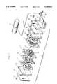
- FIG. 1is an exploded view of a cryotrap incorporating the presently preferred embodiment of the invention
- FIG. 2is an enlarged and exploded view of the core and coil of the cryotrap of FIG. 1;
- FIG. 3is a side view of the core plate of FIG. 1;
- FIG. 4is an enlarged sectional view taken along the line 4--4 of FIG. 3;
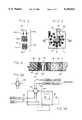
- FIG. 5Ais a diagram illustrating the operation of the cryotrap, with the control valve in the sampling position.
- FIG. 5Bis a diagram similar to that of FIG. 5A with the control valve in the flushing position.
- FIG. 6is an electrical block diagram for the cryotrap.
- a core plate 11, apertured insulator plates 12, solid insulator plates 13, and a mounting plate 14are held together in a sandwich construction by rods 15 and screws 16 positioned at the corners of the plates.
- a core 19is positioned in the core plate 11 and a gas expander 20 is attached to the mounting plate 14 by screws 21, with the tube 22 of the gas expander extending through openings 23 in the plates and into an axial opening 24 in the core 19.
- a thermally conductive compoundsuch as silver-loaded silicone grease may be applied to the end of the expander tube 22 to improve the thermal connection to the core 19.
- the gas expanderis part of a refrigeration system which provides for cooling of the core 19.
- a Stirling linear cooleris utilized, having a compressor 27 connected to the gas expander by a line 28.
- the Stirling linear coolermay be of conventional design, providing a closed cycle with helium being compressed at the compressor and with pressure pulses transferred through the helium to the expander. Cooling is obtained by cyclic out-of-phase motion of a compression piston and a displacer-regenerator located in the expander assembly.
- the compressoris operated for a time prior to the introduction of the sample to allow the core and tubing to reach the desired operating temperature.
- the compressorcontinues to operate during the time that the sample is passed through the trap tubing.
- the compressoris then turned off during the heating mode.
- the core 19preferably is a copper cylinder 30 with a helical groove 31 on the exterior.
- Temperature sensors 33a, 33bmay be positioned in openings 34 in the core, preferably between the gas expander opening 24 and the helical groove B1. The temperature sensors are connected to a control circuit as shown in FIG. 6 by wires 35.
- a flexible heater 36is placed on the core over the tubing and typically is a Kapton film heater consisting of a resistive metallic foil heater element insulated on both sides by a thin film of Kapton polyimide.
- a layer of aluminum foilis bonded to the back of the heater to distribute the heat evenly and a layer of pressure sensitive adhesive is applied to the aluminum.
- the pressure sensitive adhesiveserves to temporarily hold the heater to the core. Copper foils with a pressure sensitive adhesive on one side are then wrapped around the heater and core and soldered in place. The copper foil serves to hold the heater in place.
- the compressor control electronicshold the core temperature to a selectable preset temperature as sensed by the temperature sensor 33a.
- the heater temperature controller 52holds the core temperature to a selectable preset temperature as sensed by the temperature sensor 33b.
- the heater temperature controlleralso provides a display of the core temperature. Cooling and heating modes are controlled by the cryotrap sequence control electronics 53, with power from adc power supply 54.
- the core plate 11 and insulator plates 12, 13are formed of a low density, closed cell, rigid foam for thermal insulation, typically a polymethacrylimide foam.
- the individual platespreferably are about 1/2" thick and about 4" ⁇ 4" square.
- a layer of moralized plastic film 40, typically aluminized Mylar film,is positioned on each side of each plate, typically about 0.0005" thick.
- a plurality of openings 41are provided in each of the core plate and insulator plates, typically about 1/2" in diameter. Prior to applying the surface layers 40, the openings preferably are filled with crumpled metalized plastic film 42, typically aluminized Mylar film. Also, preferably the openings 41 in adjacent plates are misaligned, as seen in FIG. 1.
- the coreis cooled by the gas expander rod 22 in the opening 24 of the core.
- Substantial insulationis provided around the core and the gas expander tube so there is minimal heating from the surrounding atmosphere.
- heatis periodically applied to the tubing for thawing the frozen gas constituents.
- good heat transmission between the heater and the tubingis desired. It has been found that the insulation construction using the foam plates, with the crumpled metalized film in the openings 41 achieves an excellent balance between heating and cooling, permitting freezing of substantially all constituents in the gas while at the same time requiring a minimum of cooling energy and permitting a rapid cycle time.
- the cryotrapis utilized with a six port valve 44 which is movable between a sampling position shown in FIG. 5A and a flushing position shown in FIG. 5B.
- a source of sample gasis connected to the valve through a line 45, and a vent for the sample gas is connected to the valve through another line 46.
- the carrier gas from an analyzer such as a gas chromatographis connected to the valve by an incoming line 47 and an outgoing line 48.
- the tubing 32is connected to the valve 44 by lines 49, 50.
- the sample gasflows through the line 45, the valve 44, through the tubing 32, and back through the valve to the vent line 46, with the carrier gas flowing directly to and from the valve through lines 47, 48.
- the sample gasflows directly into and out of the valve, with the carrier gas flowing through the line 47 to the valve, through the tubing 32 and back to the analyzer through the valve and the line 48.
- the operation of the valvemay be automatic, operating on a predetermined cycle or may be manually operated as desired.
Landscapes
- Chemical & Material Sciences (AREA)
- Chemical Kinetics & Catalysis (AREA)
- Sampling And Sample Adjustment (AREA)
Abstract
Description
This invention relates to air pollution analyzers and the like which measure constituents in a sample gas stream. More particularly, the invention relates to a cryotrap used for extracting constituents from the sample gas.
In a typical air pollution application, the air sample is passed through a cryotrap which is maintained at the temperature of liquid nitrogen or other liquid cryogens. Constituents in the gas sample are frozen by the low temperature and solidify on the cold surfaces of the trap. After the desired amount of sample gas has passed through the trap, the gas flow path is changed so as to pass a carrier gas through the trap in place of the sample gas. At this time, the trap is heated. The frozen constituents vaporize and are carried away with the carrier gas to an analyzer or other instrument. The now clean trap is ready for another sampling and flushing cycle.
In the cryotraps commonly used, liquid nitrogen is the gas chosen for the freezing step. However, the liquid nitrogen is lost to the atmosphere and a new quantity must be utilized for each operation. For instruments which operate continuously, the cost of liquid nitrogen as the freezing gas is very high.
It is an object of the present invention to provide a new and improved cryotrap which uses a closed cycle cooler for the freezing with no coolant being discharged after each sampling cycle.
A further object of the invention is to provide such a cryotrap with a new and improved construction for obtaining increased efficiency in cooling and heating while enabling a smaller construction and shorter operating cycles.
Earlier mechanical coolers are bulky, heavy, noisy, and have high mechanical vibration. They have relatively short life cycles and do not cool to liquid nitrogen temperature. It is an object of the present invention to use a Stirling closed cycle linear cooler which is relatively lightweight and compact. Features of the Stirling cooler include low conducted and radiated emissions, low mechanical vibration, acoustically quiet operation, and improved lifetime and reliability.
Other objects, advantages, features and results will more fully appear in the course of the following description.
The cryotrap of the invention includes a core having first means for receiving a cooling gas expander, a length of tubing carried on the core defining a gas flow path around the gas expander, and an electric heater on the core, with the tubing disposed between the heater and expander. The core preferably has a helical groove around the exterior thereof, with the tubing positioned in the groove, and with the heater positioned around the core over the tubing. The core may be a cylindrical copper rod with a helical groove on the exterior with the tubing wound therein, and an axial opening for the gas expander, and including a copper foil wrapped around the core over the heater.
The source of cooling may comprise a Stirling linear drive cooler charged with helium and having a gas compressor connected to one end of the gas expander with the other end of the expander positioned in the core.
Insulation for the cryotrap preferably includes a support for the core having a first central plate and a plurality of second insulator plates, with at least one second plate on each side of the first plate, and with the core positioned in the first plate. Each of the first and second plates is of a low density, closed cell, rigid foam thermal insulation with a plurality of openings therethrough, and metalized plastic film on each side of the plate, and includes crumpled metalized plastic film filling the openings of the second plate. A plurality of third insulator plates may be used with at least one third plate on each side of the first and second plate combination, and a fourth mounting plate on a side of the first, second and third plate combination with the plates joined in a sandwich construction.
FIG. 1 is an exploded view of a cryotrap incorporating the presently preferred embodiment of the invention;
FIG. 2 is an enlarged and exploded view of the core and coil of the cryotrap of FIG. 1;
FIG. 3 is a side view of the core plate of FIG. 1;
FIG. 4 is an enlarged sectional view taken along the line 4--4 of FIG. 3;
FIG. 5A is a diagram illustrating the operation of the cryotrap, with the control valve in the sampling position; and
FIG. 5B is a diagram similar to that of FIG. 5A with the control valve in the flushing position; and
FIG. 6 is an electrical block diagram for the cryotrap.
In the cryotrap shown in FIG. 1, a core plate 11, aperturedinsulator plates 12,solid insulator plates 13, and amounting plate 14 are held together in a sandwich construction byrods 15 andscrews 16 positioned at the corners of the plates. Acore 19 is positioned in the core plate 11 and agas expander 20 is attached to themounting plate 14 byscrews 21, with thetube 22 of the gas expander extending throughopenings 23 in the plates and into anaxial opening 24 in thecore 19. A thermally conductive compound such as silver-loaded silicone grease may be applied to the end of theexpander tube 22 to improve the thermal connection to thecore 19.
The gas expander is part of a refrigeration system which provides for cooling of thecore 19. In the preferred embodiment illustrated, a Stirling linear cooler is utilized, having acompressor 27 connected to the gas expander by aline 28. The Stirling linear cooler may be of conventional design, providing a closed cycle with helium being compressed at the compressor and with pressure pulses transferred through the helium to the expander. Cooling is obtained by cyclic out-of-phase motion of a compression piston and a displacer-regenerator located in the expander assembly.
The compressor is operated for a time prior to the introduction of the sample to allow the core and tubing to reach the desired operating temperature. The compressor continues to operate during the time that the sample is passed through the trap tubing. The compressor is then turned off during the heating mode.
The preferred construction for the core and the plates is shown in greater detail in FIGS. 2-4. Thecore 19 preferably is acopper cylinder 30 with ahelical groove 31 on the exterior. A length oftubing 32, preferably of stainless steel, is wound on the core in the helical groove.Temperature sensors 33a, 33b may be positioned inopenings 34 in the core, preferably between the gas expander opening 24 and the helical groove B1. The temperature sensors are connected to a control circuit as shown in FIG. 6 bywires 35.
Aflexible heater 36 is placed on the core over the tubing and typically is a Kapton film heater consisting of a resistive metallic foil heater element insulated on both sides by a thin film of Kapton polyimide. A layer of aluminum foil is bonded to the back of the heater to distribute the heat evenly and a layer of pressure sensitive adhesive is applied to the aluminum. The pressure sensitive adhesive serves to temporarily hold the heater to the core. Copper foils with a pressure sensitive adhesive on one side are then wrapped around the heater and core and soldered in place. The copper foil serves to hold the heater in place.
During the cooling mode the compressor control electronics hold the core temperature to a selectable preset temperature as sensed by thetemperature sensor 33a. During the heating mode theheater temperature controller 52 holds the core temperature to a selectable preset temperature as sensed by the temperature sensor 33b. The heater temperature controller also provides a display of the core temperature. Cooling and heating modes are controlled by the cryotrapsequence control electronics 53, with power fromadc power supply 54.
Desirably, the core plate 11 andinsulator plates plastic film 40, typically aluminized Mylar film, is positioned on each side of each plate, typically about 0.0005" thick.
A plurality ofopenings 41 are provided in each of the core plate and insulator plates, typically about 1/2" in diameter. Prior to applying the surface layers 40, the openings preferably are filled with crumpledmetalized plastic film 42, typically aluminized Mylar film. Also, preferably theopenings 41 in adjacent plates are misaligned, as seen in FIG. 1.
In operation, the core is cooled by thegas expander rod 22 in theopening 24 of the core. Substantial insulation is provided around the core and the gas expander tube so there is minimal heating from the surrounding atmosphere. At the same time, heat is periodically applied to the tubing for thawing the frozen gas constituents. Hence, good heat transmission between the heater and the tubing is desired. It has been found that the insulation construction using the foam plates, with the crumpled metalized film in theopenings 41 achieves an excellent balance between heating and cooling, permitting freezing of substantially all constituents in the gas while at the same time requiring a minimum of cooling energy and permitting a rapid cycle time.
It is desirable to cool the core quickly. Rapid cooling minimizes wear on the Stirling cooler and enables the cryotrap to complete a cooling/heating cycle quickly. To cool the core quickly it is necessary to minimize the amount of material that must be cooled. This includes the insulating material around the core, therefore insulating material is removed resulting in a plurality ofopenings 41 in each of the core plates and insulator plates. The openings are typically 1/2" in diameter leaving a "web" of foam insulation to support the core and providing a longer path through the foam from the core to the outside. To prevent air currents from circulating in these openings, the openings are filled with crumpledmetalized plastic film 42, typically aluminized Mylar film. Metalized plastic film is also bonded to each side of the insulating plate. The metalized plastic film also serves to reflect external radiant energy away from the core.
The cryotrap is utilized with a sixport valve 44 which is movable between a sampling position shown in FIG. 5A and a flushing position shown in FIG. 5B. A source of sample gas is connected to the valve through aline 45, and a vent for the sample gas is connected to the valve through anotherline 46. The carrier gas from an analyzer such as a gas chromatograph is connected to the valve by anincoming line 47 and anoutgoing line 48. Thetubing 32 is connected to thevalve 44 bylines
During the sampling mode, the sample gas flows through theline 45, thevalve 44, through thetubing 32, and back through the valve to thevent line 46, with the carrier gas flowing directly to and from the valve throughlines
With the valve turned to the flushing mode, the sample gas flows directly into and out of the valve, with the carrier gas flowing through theline 47 to the valve, through thetubing 32 and back to the analyzer through the valve and theline 48.
The operation of the valve may be automatic, operating on a predetermined cycle or may be manually operated as desired.
Claims (13)
1. In a cryotrap for an air pollution analyzer, the combination of:
a core having first means for receiving a cooling gas expander;
a length of tubing carried on said core defining a gas flow path around said gas expander; and
an electric heater on said core, with said tubing disposed between said heater and expander;
said core having a helical groove around the exterior thereof, with said length of tubing positioned in said groove, and with said heater positioned around said core over said tubing.
2. A cryotrap as defined in claim 1 wherein said core is a cylindrical copper rod with a helical groove around the exterior with said tubing wound therein, with an axial opening for said gas expander, and including a copper foil wrapped around said core over said heater.
3. A cryotrap as defined in claim 2 including a second opening in said core between said axial opening and said helical groove for receiving a temperature sensor.
4. A cryotrap as defined in claim 1 including a Stirling linear drive cooler charged with helium and having a gas compressor connected to one end of said gas expander with the other end of said expander positioned in said core.
5. In a cryotrap for an air pollution analyzer, the combination of:
a core having first means for receiving a cooling gas expander;
a length of tubing carried on said core defining a gas flow path around said gas expander;
an electric heater on said core, with said tubing disposed between said heater and expander; and
a support for said core having a first central plate and a plurality of second insulator plates, with at least one second plate on each side of said first plate, and with said core positioned in said first plate.
6. A cryotrap as defined in claim 5 wherein each of said first and second plates is of a low density, closed cell, rigid foam thermal insulation with a plurality of insulator openings therethrough, and metalized plastic film on each side of the plate.
7. A cryotrap as defined in claim 6 including crumpled metalized plastic film filling said insulator openings of said second plates.
8. A cryotrap as defined in claim 7 including a plurality of third insulator plates with at least one third plate on each side of the first and second plate combination, and a fourth mounting plate on a side of the first, second and third plate combination; and
means for joining said plates in a sandwich construction;
with each of said third plates of a low density, closed cell, rigid foam thermal insulation and an metalized plastic film on each side of the plate; and
with aligned expander openings through the second, third and fourth plates on one side of said first plate aligned with said core in said first plate for receiving said gas expander.
9. A cryotrap as defined in claim 8 wherein said insulator openings in adjacent plates are out of alignment with each other.
10. A cryotrap as defined in claim 9 wherein said plates are in the order of 1/2 inch thick and square and about 4 inches long on a side.
11. In a cryotrap for an air pollution analyzer, the combination of:
a core having a first opening for receiving a cooling gas expander and a helical groove around the exterior thereof;
a length of tubing carried on said core in said helical groove and defining a gas flow path around said gas expander;
an electric heater on said core, positioned around said core over said tubing;
a copper foil wrapped around said core over said heater; and
a support for said core having a first central plate and a plurality of second insulator plates, with at least one second plate on each side of said first plate, and with said core positioned in said first plate,
with each of said first and second plates of a low density, closed cell, rigid foam thermal insulation with a plurality of openings therethrough, and a metalized plastic film on each side of the plate, and with crumpled metalized plastic film filling said openings of said second plates.
12. A cryotrap as defined in claim 11 including a Stirling linear drive cooler charged with helium and having a gas compressor connected to one end of said gas expander with the other end of said expander positioned in said axial opening of said core.
13. A cryotrap as defined in claim 12 including a plurality of third insulator plates with at least one third plate on each side of the first and second plate combination, and a fourth mounting plate on a side of the first, second and third plate combination; and
means for joining said plates in a sandwich construction;
with each of said third plates of a low density, closed cell, rigid foam thermal insulation and a metalized plastic film on each side of the plate; and
with aligned openings through the second, third and fourth plates on one side of said first plate aligned with said axial opening of said first plate for receiving said gas expander.
Priority Applications (1)
| Application Number | Priority Date | Filing Date | Title |
|---|---|---|---|
| US08/020,981US5349833A (en) | 1993-02-22 | 1993-02-22 | Cryotrap for air pollution analyzer |
Applications Claiming Priority (1)
| Application Number | Priority Date | Filing Date | Title |
|---|---|---|---|
| US08/020,981US5349833A (en) | 1993-02-22 | 1993-02-22 | Cryotrap for air pollution analyzer |
Publications (1)
| Publication Number | Publication Date |
|---|---|
| US5349833Atrue US5349833A (en) | 1994-09-27 |
Family
ID=21801681
Family Applications (1)
| Application Number | Title | Priority Date | Filing Date |
|---|---|---|---|
| US08/020,981Expired - LifetimeUS5349833A (en) | 1993-02-22 | 1993-02-22 | Cryotrap for air pollution analyzer |
Country Status (1)
| Country | Link |
|---|---|
| US (1) | US5349833A (en) |
Cited By (6)
| Publication number | Priority date | Publication date | Assignee | Title |
|---|---|---|---|---|
| US5847291A (en)* | 1995-11-13 | 1998-12-08 | Tekmar Company | Air sampler with trap |
| US20080006099A1 (en)* | 2005-01-25 | 2008-01-10 | Oscillogy Llc | Temperature Controller for Small Fluid Samples With Different Heat Capacities |
| US20130055791A1 (en)* | 2010-02-12 | 2013-03-07 | Gl Sciences Incorporated | Sample trapping method and sample trapping apparatus |
| US20140080221A1 (en)* | 2012-09-14 | 2014-03-20 | Wayne Allen Stollings | Semi-Continious Non-Methane Organic Carbon Analyzer |
| US20160144564A1 (en)* | 2014-07-18 | 2016-05-26 | Fusion3 Design LLC | Apparatus and method for fabricating three-dimensional objects |
| IT202300002766A1 (en)* | 2023-02-17 | 2024-08-17 | Snf Envirotech Srl | SYSTEM FOR HEAT REMOVAL FROM A FLUID TO BE COOLED |
Citations (17)
| Publication number | Priority date | Publication date | Assignee | Title |
|---|---|---|---|---|
| US2880615A (en)* | 1954-11-30 | 1959-04-07 | Exxon Research Engineering Co | Vapor sampler |
| US3485054A (en)* | 1966-10-27 | 1969-12-23 | Cryogenic Technology Inc | Rapid pump-down vacuum chambers incorporating cryopumps |
| US3611812A (en)* | 1970-05-13 | 1971-10-12 | Olson Lab Inc | Sampling process for combustion gases |
| US3673871A (en)* | 1971-06-28 | 1972-07-04 | Us Air Force | Portable liquid gas sampler system |
| US3712074A (en)* | 1970-04-17 | 1973-01-23 | Air Liquide | Cryogenic gas trap |
| US3881359A (en)* | 1974-04-26 | 1975-05-06 | Us Navy | Hot atmosphere particulate sampler |
| US4148196A (en)* | 1977-04-25 | 1979-04-10 | Sciex Inc. | Multiple stage cryogenic pump and method of pumping |
| US4154088A (en)* | 1975-02-12 | 1979-05-15 | F. L. Smidth & Co. | Apparatus for measuring the particulate matter content of a gas |
| US4283948A (en)* | 1979-12-21 | 1981-08-18 | Air Products And Chemicals, Inc. | Cryogenic air sampler |
| US4425811A (en)* | 1979-10-19 | 1984-01-17 | Kernforschungsanlage Julch GmbH | Cryogenic pump and air sampler |
| US4479927A (en)* | 1982-08-09 | 1984-10-30 | The Perkin-Elmer Corporation | Regenerable cold trap for aluminum chloride effluent |
| US4506513A (en)* | 1983-06-17 | 1985-03-26 | Max John K | Cold trap |
| US4607491A (en)* | 1984-01-27 | 1986-08-26 | Hajime Ishimaru | Cooling trap for vacuum |
| US4677863A (en)* | 1984-04-12 | 1987-07-07 | The United States Of America As Represented By The United States Department Of Energy | Sub-micron particle sampler apparatus |
| US4964278A (en)* | 1989-03-06 | 1990-10-23 | American Air Liquide | Method of separating condensible vapors from particles in highly compressed gases |
| US4977749A (en)* | 1989-04-25 | 1990-12-18 | Sercel Jeffrey P | Apparatus and method for purification of gases used in exciplex (excimer) lasers |
| US5073896A (en)* | 1991-04-18 | 1991-12-17 | Lumonics Inc. | Purification of laser gases |
- 1993
- 1993-02-22USUS08/020,981patent/US5349833A/ennot_activeExpired - Lifetime
Patent Citations (17)
| Publication number | Priority date | Publication date | Assignee | Title |
|---|---|---|---|---|
| US2880615A (en)* | 1954-11-30 | 1959-04-07 | Exxon Research Engineering Co | Vapor sampler |
| US3485054A (en)* | 1966-10-27 | 1969-12-23 | Cryogenic Technology Inc | Rapid pump-down vacuum chambers incorporating cryopumps |
| US3712074A (en)* | 1970-04-17 | 1973-01-23 | Air Liquide | Cryogenic gas trap |
| US3611812A (en)* | 1970-05-13 | 1971-10-12 | Olson Lab Inc | Sampling process for combustion gases |
| US3673871A (en)* | 1971-06-28 | 1972-07-04 | Us Air Force | Portable liquid gas sampler system |
| US3881359A (en)* | 1974-04-26 | 1975-05-06 | Us Navy | Hot atmosphere particulate sampler |
| US4154088A (en)* | 1975-02-12 | 1979-05-15 | F. L. Smidth & Co. | Apparatus for measuring the particulate matter content of a gas |
| US4148196A (en)* | 1977-04-25 | 1979-04-10 | Sciex Inc. | Multiple stage cryogenic pump and method of pumping |
| US4425811A (en)* | 1979-10-19 | 1984-01-17 | Kernforschungsanlage Julch GmbH | Cryogenic pump and air sampler |
| US4283948A (en)* | 1979-12-21 | 1981-08-18 | Air Products And Chemicals, Inc. | Cryogenic air sampler |
| US4479927A (en)* | 1982-08-09 | 1984-10-30 | The Perkin-Elmer Corporation | Regenerable cold trap for aluminum chloride effluent |
| US4506513A (en)* | 1983-06-17 | 1985-03-26 | Max John K | Cold trap |
| US4607491A (en)* | 1984-01-27 | 1986-08-26 | Hajime Ishimaru | Cooling trap for vacuum |
| US4677863A (en)* | 1984-04-12 | 1987-07-07 | The United States Of America As Represented By The United States Department Of Energy | Sub-micron particle sampler apparatus |
| US4964278A (en)* | 1989-03-06 | 1990-10-23 | American Air Liquide | Method of separating condensible vapors from particles in highly compressed gases |
| US4977749A (en)* | 1989-04-25 | 1990-12-18 | Sercel Jeffrey P | Apparatus and method for purification of gases used in exciplex (excimer) lasers |
| US5073896A (en)* | 1991-04-18 | 1991-12-17 | Lumonics Inc. | Purification of laser gases |
Cited By (9)
| Publication number | Priority date | Publication date | Assignee | Title |
|---|---|---|---|---|
| US5847291A (en)* | 1995-11-13 | 1998-12-08 | Tekmar Company | Air sampler with trap |
| US20080006099A1 (en)* | 2005-01-25 | 2008-01-10 | Oscillogy Llc | Temperature Controller for Small Fluid Samples With Different Heat Capacities |
| US7841247B2 (en)* | 2005-01-25 | 2010-11-30 | Oscillogy Llc | Temperature controller for small fluid samples with different heat capacities |
| US20130055791A1 (en)* | 2010-02-12 | 2013-03-07 | Gl Sciences Incorporated | Sample trapping method and sample trapping apparatus |
| US20140080221A1 (en)* | 2012-09-14 | 2014-03-20 | Wayne Allen Stollings | Semi-Continious Non-Methane Organic Carbon Analyzer |
| US9791425B2 (en)* | 2012-09-14 | 2017-10-17 | Wayne Allen Stollings | Semi-continious non-methane organic carbon analyzer |
| US20160144564A1 (en)* | 2014-07-18 | 2016-05-26 | Fusion3 Design LLC | Apparatus and method for fabricating three-dimensional objects |
| US10780628B2 (en)* | 2014-07-18 | 2020-09-22 | Fusion3 Design LLC | Apparatus and method for fabricating three-dimensional objects |
| IT202300002766A1 (en)* | 2023-02-17 | 2024-08-17 | Snf Envirotech Srl | SYSTEM FOR HEAT REMOVAL FROM A FLUID TO BE COOLED |
Similar Documents
| Publication | Publication Date | Title |
|---|---|---|
| US9791425B2 (en) | Semi-continious non-methane organic carbon analyzer | |
| US6682699B2 (en) | Reduced power consumption gas chromatograph system | |
| US5585772A (en) | Magnetostrictive superconducting actuator | |
| US7667476B2 (en) | Measuring module for rapid measurement of electrical, electronic and mechanical components at cryogenic temperatures and measuring device having such a module | |
| Frossati | Experimental techniques: Methods for cooling below 300 mK | |
| Rondeaux et al. | Thermal conductivity measurements of epoxy systems at low temperature | |
| US5349833A (en) | Cryotrap for air pollution analyzer | |
| US20080227647A1 (en) | Current lead with high temperature superconductor for superconducting magnets in a cryostat | |
| EP1891431A2 (en) | Thermal modulation for gas chromatography | |
| JP3898231B2 (en) | Current supply for cooling electrical equipment | |
| US20070051115A1 (en) | Cryostat configuration with cryocooler and gas gap heat transfer device | |
| JP4142754B2 (en) | Permanent magnet system | |
| EP0136687B1 (en) | Infrared receiver | |
| Prashantha et al. | Design construction and performance of 10 W thermoacoustic refrigerators | |
| JPH11337631A (en) | Strong magnetic field low-temperature device for measuring physical property | |
| JPH07324991A (en) | Apparatus for measuring thermoelectric characteristic | |
| JPH06249902A (en) | Superconducting-critical-current measuring apparatus | |
| JP2952552B2 (en) | Current leads for superconducting equipment | |
| Jirmanus | Introduction to laboratory cryogenics | |
| JP4275640B2 (en) | Cryogenic cooling device | |
| Freund et al. | Design and flight performance of a space borne 3He refrigerator for the infrared telescope in space | |
| JP2020031119A (en) | Superconducting magnet | |
| McKinley et al. | Characterization testing of Lockheed Martin Micro1-2 cryocoolers for the Mapping Imaging Spectrometer for Europa (MISE) instrument | |
| JP6172979B2 (en) | Superconducting device | |
| JP2001066354A (en) | Cryogenic container for storing superconducting quantum interference devices |
Legal Events
| Date | Code | Title | Description |
|---|---|---|---|
| AS | Assignment | Owner name:XONTECH, INC., CALIFORNIA Free format text:ASSIGNMENT OF ASSIGNORS INTEREST.;ASSIGNORS:PARDEE, MICHAEL A.;YOONG, MATTHIAS J.C.;REEL/FRAME:006450/0567 Effective date:19930216 | |
| FPAY | Fee payment | Year of fee payment:4 | |
| FPAY | Fee payment | Year of fee payment:8 | |
| REMI | Maintenance fee reminder mailed | ||
| AS | Assignment | Owner name:RM ENVIRONMENTAL SYSTEMS INC., CALIFORNIA Free format text:PURCHASE AGREEMENT;ASSIGNOR:XONTECH, INC.;REEL/FRAME:012875/0084 Effective date:20011031 | |
| REMI | Maintenance fee reminder mailed | ||
| REIN | Reinstatement after maintenance fee payment confirmed | ||
| FP | Lapsed due to failure to pay maintenance fee | Effective date:20060927 | |
| FEPP | Fee payment procedure | Free format text:PETITION RELATED TO MAINTENANCE FEES FILED (ORIGINAL EVENT CODE: PMFP); ENTITY STATUS OF PATENT OWNER: SMALL ENTITY | |
| FEPP | Fee payment procedure | Free format text:PETITION RELATED TO MAINTENANCE FEES GRANTED (ORIGINAL EVENT CODE: PMFG); ENTITY STATUS OF PATENT OWNER: SMALL ENTITY | |
| FPAY | Fee payment | Year of fee payment:12 | |
| SULP | Surcharge for late payment | ||
| PRDP | Patent reinstated due to the acceptance of a late maintenance fee | Effective date:20080822 | |
| STCF | Information on status: patent grant | Free format text:PATENTED CASE |