US5349640A - Option bus adapter - Google Patents
Option bus adapterDownload PDFInfo
- Publication number
- US5349640A US5349640AUS08/082,658US8265893AUS5349640AUS 5349640 AUS5349640 AUS 5349640AUS 8265893 AUS8265893 AUS 8265893AUS 5349640 AUS5349640 AUS 5349640A
- Authority
- US
- United States
- Prior art keywords
- option
- data
- telephony
- bus
- telephone
- Prior art date
- Legal status (The legal status is an assumption and is not a legal conclusion. Google has not performed a legal analysis and makes no representation as to the accuracy of the status listed.)
- Expired - Lifetime
Links
- 238000000034methodMethods0.000claimsabstractdescription14
- 238000004891communicationMethods0.000claimsdescription34
- 230000004044responseEffects0.000claimsdescription9
- 238000012545processingMethods0.000claimsdescription5
- 238000012546transferMethods0.000description19
- 238000010586diagramMethods0.000description12
- 230000006870functionEffects0.000description9
- TVZRAEYQIKYCPH-UHFFFAOYSA-N3-(trimethylsilyl)propane-1-sulfonic acidChemical compoundC[Si](C)(C)CCCS(O)(=O)=OTVZRAEYQIKYCPH-UHFFFAOYSA-N0.000description7
- 230000001360synchronised effectEffects0.000description6
- 230000002093peripheral effectEffects0.000description4
- 230000009471actionEffects0.000description3
- 230000000694effectsEffects0.000description3
- 230000001404mediated effectEffects0.000description2
- 238000012544monitoring processMethods0.000description2
- 230000008569processEffects0.000description2
- 230000005236sound signalEffects0.000description2
- 238000011144upstream manufacturingMethods0.000description2
- 230000005540biological transmissionEffects0.000description1
- 238000006243chemical reactionMethods0.000description1
- 239000004020conductorSubstances0.000description1
- 239000000835fiberSubstances0.000description1
- 238000012360testing methodMethods0.000description1
Images


Classifications
- H—ELECTRICITY
- H04—ELECTRIC COMMUNICATION TECHNIQUE
- H04M—TELEPHONIC COMMUNICATION
- H04M1/00—Substation equipment, e.g. for use by subscribers
- H04M1/253—Telephone sets using digital voice transmission
- H—ELECTRICITY
- H04—ELECTRIC COMMUNICATION TECHNIQUE
- H04M—TELEPHONIC COMMUNICATION
- H04M1/00—Substation equipment, e.g. for use by subscribers
- H04M1/60—Substation equipment, e.g. for use by subscribers including speech amplifiers
- H04M1/6033—Substation equipment, e.g. for use by subscribers including speech amplifiers for providing handsfree use or a loudspeaker mode in telephone sets
- H—ELECTRICITY
- H04—ELECTRIC COMMUNICATION TECHNIQUE
- H04M—TELEPHONIC COMMUNICATION
- H04M11/00—Telephonic communication systems specially adapted for combination with other electrical systems
- H04M11/06—Simultaneous speech and data transmission, e.g. telegraphic transmission over the same conductors
- H—ELECTRICITY
- H04—ELECTRIC COMMUNICATION TECHNIQUE
- H04Q—SELECTING
- H04Q11/00—Selecting arrangements for multiplex systems
- H04Q11/04—Selecting arrangements for multiplex systems for time-division multiplexing
- H04Q11/0428—Integrated services digital network, i.e. systems for transmission of different types of digitised signals, e.g. speech, data, telecentral, television signals
- H04Q11/0435—Details
Definitions
- This inventionrelates to a telephone control interface system for use with digital telephones using a bus protocol which is coupled to programmable computer control.
- Option buscommon bus
- the Option Busprovides a method and apparatus for connecting remote options to a digital telephone base.
- the methodprovides physical and communications protocols for connections and provides a flexible control scheme which can be as simple or elaborate as a given option requires.
- the ROLMphone 600includes an option bay connection, having a hierarchical control protocol to a digital telephone and makes available several types of information, including local analog audio, analog voice, digital voice, digital data and telephone control streams.
- DCOData Communications Option
- APIapplications programming interface
- the API interfaceis useful because it provides an abstraction of telephony control that is more straightforward to a programmer than the actual telephone control protocol used in the telephone. Consequently, however, the DCO does not always present to the programmable computing device a detailed and accurate picture of what is happening within the telephone. In addition, the DCO may report information that is moving within the telephone, but in many instances does not provide a method to alter or altogether stop the flow of control information within the telephone. Further, the DCO operates at a fixed option bus priority and thus can only provide a "picture" of activities from its view of the option bus. Finally, the DCO is an expensive option, costing roughly the same amount as the telephone itself.
- What is neededis a way for the user to be able to directly monitor and manipulate the telephone control information at the programmable computing device by having all of the telephone control information received at an option slot in an unaltered form. It would also be desirable to allow the user to select the priority of the option on the bus and thus customize the function of the telephone.
- a system and method of providing all option control bus information to a programmable computing devicethere is provided a system and method of providing all option control bus information to a programmable computing device.
- a user installable optionis provided in the form of Option Bus Adaptor.
- the Option Bus Adaptorpasses that information to a programmable computing device over a standard RS-232 connection.
- the Option Bus Adaptortakes any information received from the programmable computing device via the RS-232 connection and sends it over the telephone's option bus, observing proper option control bus rules.
- the programmable computing deviceIt is the responsibility of the programmable computing device to send any received telephony control information that should continue on in the telephone back to the Option Bus Adaptor once it has been examined and/or modified. Thus the programmable computing device can delete undesirable control information from the control information that continues on in the telephone.
- FIG. 1is a diagram of a digital telephone according to an embodiment of the present invention
- FIG. 2details the components of the Option Bus of FIG. 1;
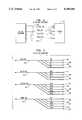
- FIG. 3is a more detailed diagram showing the component signal lines of the Data Bus, Audio Bus, Control Bus and Power Bus of FIG. 2;
- FIG. 4is a diagram of the frame format of the data and its relationship to the control signals on the Data Bus of FIGS. 1-3;
- FIG. 5is a more detailed diagram of the Audio Control Block of FIG. 2, showing an example of an interconnection with two options by way of the Option Bus;
- FIG. 6is a flow diagram of message flow in an embodiment having two options
- FIG. 7is a flow diagram showing how command flow in the embodiment of FIG. 6 is accomplished.
- FIG. 8is a flow diagram showing how event flow in the embodiment of FIG. 6 is accomplished.
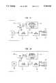
- FIG. 9is a block diagram of an Option Control Bus Adaptor (OCBA).
- OCBAOption Control Bus Adaptor
- FIG. 10is a flow diagram of the operation of the main loop of the OCBA firmware
- FIG. 11is a block diagram of a message flow where a downlink message from a PBX is altered
- FIG. 12is a block diagram of a message flow where an uplink message intended for a PBX is altered
- FIG. 13is a block diagram of an Option Bus Adapter.
- FIG. 1A telephone of a type that can be used in conjunction with the present invention is illustrated schematically in FIG. 1.
- the telephoneincludes a connection to a digital telephone line 102 (e.g. a ROLMlink line) and one or more connections for optional peripherals 104.
- the optional peripherals 104will alternately be referred to in this disclosure as Option modules 104.
- the telephonealso has a handset 106, speaker 108, microphone 110, display 112, and keyboard 114 with keys and indicators.
- the telephoneis connected to the digital telephone line 102 via the link interface 116 which handles transfers of telephone control information between a microcontroller 118 and the digital telephone line 102.
- the link interface 116also translates the digital telephone line's voice and data format to the data format used on the Option Data Bus 120.
- the link interface 116also provides miscellaneous timing signals required by the rest of the telephone.
- a power supply 122which converts the telephone line's voltage to other voltages required by the telephone. These voltages are distributed within the telephone on a Power Bus 124.
- the microcontroller 118is connected to the link interface 116 via an Option Control Bus 126.
- the microcontroller 118is a conventional microprocessor which controls all the telephone's functions, and is the source and destination of all communications with a private branch exchange (PBX) switch (not shown).
- PBXprivate branch exchange
- the microcontroller 118is also connected to a keyboard 114 and, optionally, to a display 112.
- the keyboard 114includes the telephone keys, the indicators and associated control logic.
- the display 112typically an LCD device, is used to display messages sent from the PBX via the digital telephone line 102, or messages from an Option module 104 sent via the Option Control Bus protocol (described more in detail later in this document).
- an external memory 128, which may be of non-volatile type,can be attached to the microcontroller 118 via the Option Control Bus 126.
- a coder/decoder (CODEC) 130is connected to the Option Data Bus 120 to convert the digital voice information to an analog form.
- the analog voiceis amplified appropriately and routed to/from a handset 106 and/or a speaker 108 and microphone 110 by an audio control block 132.
- the audio routingis controlled by connections from the microcontroller 118.
- the audio control block 132contains circuitry required for the hands-free speakerphone function.
- the audio control block 132also routes analog audio signals to/from the Option Audio Bus 134 for use by the Option modules 104.
- the Option Control Bus 126, the Option Data Bus 120, the Option Audio Bus 134 and the Power Bus 124are collected together as the Option Bus 136.
- FIG. 2further details the component busses of the Option Bus 136.
- the Option Bus 136is linked to connectors in the telephone for connection to the Option modules 104.
- the Option modules 104can be of the "plug-in" type which are user installable.
- Option modules 104include but are not limited to additional keys and indicators, headset attachment, data communications, digital voice processing, alternate telephone personality modules etc. All resources and information of the telephone can be made available to an Option module 104, regardless in which Option module 104 bay it is connected. Resources include but are not limited to the handset 106, speaker 108, microphone 110, display 112, keys and indicators 114, and ringer circuits. Information includes downlink audio, uplink audio, audio from other modules, downlink control messages, uplink event messages, downlink data, and uplink data.
- the option modulescan be of a user installable type which plug into option bays provided at the base of the telephone.
- the ROLMphone 600available from ROLM Company of Santa Clara, Calif. is an example of a telephone providing such option bays.
- the physical configuration of the optionscan be, for example, as described in U.S. patent application Ser. No. 7/903,582 (filed on Jun. 25, 1992).
- Access to the telephone resources and some of the informationis arbitrated by the microcontroller 118 via a hierarchical option control protocol (described in more detail later in this document). Not all elements of the Option Bus 136 may be required by a Option module 104. For example, additional keys and indicators (sometimes referred to as a DSS) only require the Option Control Bus 126 and only those signals are needed at its connector.
- FIG. 3details the signals included in the Option Bus 136.
- the Option Data Bus 120is based on the public domain standard GCI bus.
- the Option Data Bus 120is a bit synchronous, time division multiplexed, full duplex, serial data bus.
- Downlink data from the link interface 116is carried on Data Downstream (DD) line 302.
- Uplink datais carried on Data Upstream (DU) line 304 to the link interface 116.
- the Data Clock (DCL) line 306carries the clocking signal, sourced by the link interface 116, which is in sync with the bit transfers.
- the Frame Sync (FSC) line 308carries the FSC signal, which is indicative of the start of each data frame and is also sourced by the link interface 116.
- DDData Downstream
- DUData Upstream
- DCLData Clock
- FSCFrame Sync
- Each data frameis organized into fields, as detailed in FIG. 4. These fields include Data Communications and Data Control (DCDC) 402, data 404, voice 406, and auxiliary voice 408.
- DCDCData Communications and Data Control
- auxiliary voice 408By using the timing relationships between the FSC and DCL signals, an Option module 104 can send or receive digital data or voice.
- the CODEC 130also transfers its voice data to the link interface 116 via the Option Data Bus 120. In normal telephone operation the CODEC 130 transfers the voice data through the voice field 406. However, a special mode permits the CODEC 130 to transfer voice data through the auxiliary voice field 408, however, the voice data to and from the PBX remains in the voice field 406. This allows an Option module 104 to intercept the voice data for processing and then pass it on. This is useful for advanced digital audio processing applications.
- the Option Audio Bus 134provides Option modules 104 with access to several audio sources and destinations within the telephone.
- Downlink audio from the CODEC 130is provided on Downlink Voice (DLVn) line 310.
- Uplink audio to the CODEC 130is put onto the Uplink Voice (ULVn) line 312.
- Audio to be sent devices in the telephone basesuch as the handset 106 or the speaker 108, is put on the Base Input Voice (BIVn) line 314.
- BIVnBase Input Voice
- module bay 1 502would be connected to DLV1 504, ULV1 506, and BIV1 508; likewise module bay 2 510 would be connected to DLV2 512, ULV2 514, and BIV2 516. This facilitates the proper amplifying and combining of audio signals such that multiple modules can coexist.
- An audio toneis produced whenever a key is pressed on the telephone keypad or an extended keyboard option such as a DSS. This signal is carried on keytone (KT) line 316 to each module (not shown). All Option modules 104 have access to uplink and downlink audio whenever the telephone is active. Additionally, each Option module 104 receives, with its downlink audio, the uplink audio of the other Option modules 104. This allows the Option modules 104 to "talk" to each other. The Option modules 104 can send audio to the handset 106 receiver, the speaker 108 or both. Likewise, the Option modules 104 can receive audio from the handset 106 microphone or the speakerphone microphone 110.
- KTkeytone
- Switching of these audio pathsis controlled by the microcontroller 118 by way of a conventional multiplexer 518 and facilitated by the hierarchical option control protocol.
- a conventional speakerphone circuit 520(FIG. 5) can be installed between the speaker 108 and microphone 110 and the multiplexer 518.
- the Option Control Bus 126is based on the conventional Serial Peripheral Interface (SPI) bus.
- the Option Control Bus 126is a bit synchronous, full duplex, serial data bus.
- the Option Control Bus 126is used to transfer control information between the microcontroller 118 and the option modules 104.
- Data from the Option modules 104 to the microcontroller 118is carried on the Master In/Slave Out (MISO) line 320.
- Data from the microcontroller 118 to the Option modules 104is carried on the Master Out/Slave In (MOSI) line 318.
- the Serial Clock (SCLK) line 322carries the serial clocking signal for the data bits.
- the slave select (SS*n) line 324carries a slave select signal which enables (or addresses) transfers to option modules 104.
- Each option modulehas a unique slave select line 324 such that only one is enabled at a given time.
- the signals SS*1, SS*2 and SS*3would be provided, respectively, to ports 1, 2 and 3.
- a RESET line 326is provided on the Option Bus 136 to synchronize option modules during reset events, such as "power on", within the telephone.
- Option Power Bus 124Power to the Option modules 104 is provided by the Option Power Bus 124.
- These lines 328-336provide the logic voltages +5 V, -5 V and Data Ground (DGND) as well as an auxiliary power supply, +VAUX and -VAUX, for Option modules 104 requiring higher levels of power.
- DGNDData Ground
- Information flow between the microcontroller 118 and the option modules 104is mediated by a hierarchical option control protocol.
- Devices internal to the telephonesuch as the link interface 116 and the memory communicate with the microcontroller via the Option Control Bus 126. Though the interface is the same for these devices, the protocol used may differ from that of external option modules 104.
- FIG. 6is an example of message flow in an embodiment with two options. Independent of the physical connection of FIG. 1, options are ordered according to priority.
- a high priority optionwould typically be a data option, such as a data communications option (DCO).
- a low priority optionwould typically be an extended keyboard option (DSS).
- DCOdata communications option
- DSSextended keyboard option
- commands(messages from the PBX to the telephone) is illustrated by the set of blocks at the top of the figure. Commands flow first to the highest priority options (Message 1), to the lower priority option (Message 2) and finally to the remainder of the telephone and its associated microcontroller 118 (via Message 3).
- Eventsflow from the microcontroller 118 to the lowest priority option (Message 4), to the highest priority option (Message 5) to the PBX (Message 6).
- the microcontroller's 118 firmwareis logically split into two components: the Base Processor and the Option Processor.
- the base processorcontrols the digital telephony functions of the telephone.
- the Option Processordistributes messages to options and the Base Processor.
- an option or the Base Processorcan intercept, modify or synthesize a command or event message.
- the PBXcan independently send messages at will.
- the systemcan include any number of smart options (from zero to N).
- the flow of messagesis independent of the particular option module bay to which an option is connected. Options have no requirement of knowledge of the outside system to communicate. Operation codes contained in the messages contain no address information and only encode the direction (command or event) and the type of message.
- FIG. 7shows how the flow of command messages is accomplished.
- the PBXsends a Message 1 to the telephone. Message 1 travels from the PBX (via the link interface 116) to the Option Processor 702.
- the Option Processorthen sends Message 1 to the highest priority option (the high priority option 704).
- the high priority option 704then responds with Message 2, which is sent to the Option Processor 702.
- the Option Processor 702sends Message 2 to the next highest priority option (the low priority option 706).
- the low priority option 706generates Message 3, which is sent to the Option Processor 702.
- the Option Processor 702sends Message 3 to the Base Processor 708.
- the Base Processor 708sends Message 4 to the Option Processor 702 which, in turn, relays Message 4 to the lowest priority option (the low priority option 706).
- the low priority option 706responds with Message 5 and sends it to the Option Processor 702.
- Message 5is then sent by the Option Processor 702 to the next highest priority option (the high priority option 704).
- the high priority option 704responds with Message 6 and sends it to the Option Processor 702. As no more options exist, the Option Processor sends Message 6 to the PBX.
- An example of a typical message sequenceis a PBX request for phone ID, as illustrated by the following sequence.
- the PBXrequests a phone ID from the telephone via Message 1.
- Message 1is relayed to the high priority option 704 by the Option Processor 702.
- the high priority option 704then sends Message 1 unchanged (as Message 2), to the Option Processor 702 which, in turn relays the message to the low priority option 706.
- the low priority optionsends Message 2, unchanged, back to the Option Processor 702 as Message 3.
- the Option Processor 702then relays Message 3 to the Base Processor 708.
- the telephone baseresponds to Message 3, a request for phone ID, by identifying its ID, which it sends to the Option Processor as Message 4.
- the Option processorthen relays this message to the next highest priority option (the low priority option 702).
- the low priority option 702imparts its own ID on top of the Base phone ID (for example, if it is a DSS, indicating that more keys exist) and sends this collection of information (the Base phone ID and the low priority option ID), to the Option Processor as Message 5.
- the Option Processorthen relays Message 5 to the high priority option 706.
- the high priority option 706imparts its ID information on top of the message, for example indicating that it is a data communications option, and forwards this information (all three IDs), as an event (Message 6), to the Option Processor 702.
- the Option Processor 702receives Message 6, it relays it to the PBX.
- the final message (Message 6)indicates that the telephone contains both a data communications option and additional keys as well as information about the base model.
- an optioncan handle a message in a number of ways. Some options will receive the message, take some action, and then not forward or modify the message at all. For example, in order to turn a speaker-phone option "on" in response to a PBX command, the microcontroller will send a command over the Option Bus. In response, the speaker-phone option will activate; however, it will not relay the message. Other options may modify a message without taking any action. For example, an extended keyboard option (DSS) may respond to a command to activate an indicator (e.g. light an LED) that the DSS determines is not present, by remapping the command to an indicator that is present elsewhere (e.g. on the main telephone).
- DSSextended keyboard option
- the DSSwill then transmit the modified command to the Option Processor, in place of the original command which it received.
- the Option Processorthen forwards the modified command to the telephone's main keyboard.
- Still other optionswill take some action and modify the message as well. For example, in response to a diagnostic command, each option may perform a test, append its status to the message and then forward the message on the next option by way of the Option Processor.
- an Option for which a particular message is not intendedwill simply relay the message, unchanged, back to the Option Processor.
- Commandsare sent to and from options with polled simultaneous command exchange on the Option Control Bus 126. Only one option at a time is selected by the telephone. This is referred to as polling.
- the Option Control Bus transfersare bi-directional, and both the telephone and the option will issue a command to each other when the telephone initiates the first transfer to an option. As the telephone can issue a poll to an option at any time, an option is required to have a command available for transfer within timing constraints. If a command with a specific function is not available, a NOP command is sent. A NOP can be issued by both the telephone and an option.
- a convention for command acceptanceis used to determine if the command from the telephone or option will be accepted. If the telephone issues a command, other than a NOP, it will always be accepted, regardless of the command issued by the polled option. If the polled option issues a command, other than a NOP, and the telephone issued a NOP, the polled option command is accepted. If both sides issue a NOP, the command transfer is complete and no data is sent. An individual command may include data associated with it or be a request for specific data.
- An example of a command without associated datais an indication that the PBX issued a "phone reset".
- An example of a command with associated datais communication of a ROLMlink command.
- An example of a command with a request for datais a request for an option ID. Either the telephone or an option can issue any of the above-described types of commands.
- a No Operation (NOP) commandis issued by the Option Processor or an Option when no operation needs to be performed.
- NOPNo Operation
- the pollis complete and no more Option Control Bus transfers will occur until the next poll of the opinion.
- the non-NOP commandis always accepted. This command enables the option processor to poll options for commands. It also enables options to indicate that they have no command to issue during a poll.
- the Software Reset Option (RESET) commandis issued by the Option Processor when it wants to perform a software reset of one or more options.
- the definition of the software resetwill vary from option to option.
- the RESET commandis issued twice to ensure synchronization. Options must respond to a single command, however, since they may be out of synchronization when the first reset command occurs.
- the RESET commandis issued by the Option Processor whenever a microcontroller reset occurs.
- the Report Specified ID (REPORT) commandis issued by the Option Processor when it wants to request one of the following from an option: Option ID, Data Priority, Data Mask or Function ID.
- the commandincludes a single operand which identifies which information is to be reported.
- REPORTis a two byte command, while the response from the option is one byte containing the requested information. The information is reported by the option on the second byte of the command transfer.
- the Base Receiving Data (BRD) commandis a value which the Option Processor issues during the second transfer when the microcontroller is receiving a second transfer of a two byte command from an option.
- the valuehas no effect on the command accepted, however, it can help communicate the protocol externally to any external monitoring during debug.
- the Option Receiving Data (ORD) commandis issued by the option when it is receiving the second transfer of a two byte command from the Option Processor.
- This commandis similar to BRD in that it has no effect on the command accepted; however, it can help communicate the protocol externally to any external monitoring during debug.
- the Module Data (DATA) commandcan be issued by an option or the Option Processor.
- control dataof an encoded type, is transferred to the option to which the command is directed.
- the data direction (command or event)is specified by a one bit field (D) of the command and the type of control data (TTT) is specified by a three bit field.
- Examples of control data typesare Keyboard, Display, and Data (e.g. from a data communications option).
- the timing of commandsis as follows: Between the first and second command bytes (if a second command byte exists) at least 125 microseconds will have elapsed to allow for the option processor to respond and complete any other impending tasks. In addition, before a new command is issued, a minimum of 125 microseconds will elapse, to permit the option processor to respond and complete any other impending tasks.
- One of the options provided on the telephonecan be an Option Control Bus Adaptor (OCBA).
- OCBAOption Control Bus Adaptor
- the OCBA 902connects to the Option Bus 136, but only requires the signals of the Option Control Bus 126 and the Option Power Bus 124.
- the OCBA 902communicates with the base digital telephone via the hierarchical option control protocol as any option module would.
- the OCBA 902includes a microcontroller 904, a set of RS-232 drivers/receivers 906, a DIP switch 908, and a standard RS-232 connector 910 for connection to a standard RS-232 cable 912 and further connection to the standard RS-232 serial port 914 of a programmable computing device 916 (such as a personal computer).
- Data from the base telephone's microcontroller 118is carried to the OCBA's microcontroller 904 on the MOSI line 318.
- Data from the OCBA's microcontroller 904is carried to the telephone's microcontroller 118 by the MISO line 320.
- the SCLK 322 and SS*n 324are provided to the OCBA's microcontroller 904 and operate as previously described. Information flow between the telephone and the OCBA 902 is mediated by the hierarchical option control protocol.
- the Reset line 326is used by the OCBA 902 to synchronize during reset events within the telephone such as power on. Power is provided to the OCBA 902 from the Option Power Bus 124.
- the embodiment of the OCBA 902 shown in FIG. 9does not connect to the entire option bus 136, it can be desirable to make other information (such as that on the Option Data Bus 120) available to the programmable computing device 916 as well. Since the rate of information flow contained on this bus is much higher than what can be matched on standard RS-232 link, a faster conduit to the programmable computing device would used as described in more detail with respect to the embodiment of FIG. 13.
- the DIP switch bank 908is accessible to the user so that the user can set the switches to indicate any priority ranging from the lowest possible priority to the highest possible priority.
- the DIP switch bank 908is connected to the microcontroller 904 so that the value of the entered priority can be read for transmission over the option bus at the appropriate time.
- the microcontroller 904comprises firmware 918 which dictates its handling of the option bus protocol and information received over the RS/232 link 912, a Universal Asynchronous Receiver Transmitter (UART) 920 which handles communications over the RS-232 link 912, and a random access memory (RAM) 922 which provides workspace and queue space.
- the queues formed in the RAM 922include a "To Phone” queue which contains telephony control information received from the programmable computing device 916 and bound for the telephone and the "To Computing Device” queue which contains telephony control information which is received from the telephone and bound for the programmable computing device 916.
- a set of RS-232 Driver/Receivers 906connects the UART 920 to the a standard RS-232 physical connector 910 which provides the connection to a standard RS-232 cable 912.
- the RS-232 Driver/Receivers 920produce signals which conform to the RS-232 standard.
- the RS-232 cable 912is in turn connected to the standard RS-232 serial communications port 914 of the programmable computing device 916.
- the application program 924executing on the programmable computing device 916, sends and receives telephony control information to and from the OCBA 902 via the serial communications port 914.
- the operation of the main loop of the OCBA firmware 918is illustrated in FIG. 10.
- the "To Phone" queueis checked in step 1002. If there is no information waiting to be sent to the telephone, then a Command of NOP is placed on the option control bus (step 1004) so that it will be read when the OCBA option 902 is polled by the telephone.
- Step 1006indicates this service.
- the firmware 918checks for serial information coming from the programmable computing device 916, and if present, enqueues it for a later transfer over the option control bus 136 in the "To Phone" queue.
- the firmware 918also transmits data from the "To Computing Device” queue to the programmable computing device 916 if data is enqueued and the UART 920 is ready to transmit data.
- step 1008the firmware 918 checks to see if the Command from the telephone was a NOP command. If it was, then neither the telephone nor the OCBA 902 tried to transmit over the Option Control bus 126 and the main loop is repeated. If the Command was not a NOP, then the telephone had a command to transmit to the OCBA 902. The process of handling that command takes place starting at step 1020.
- step 1002if information was present in the "To Phone" queue, then the OCBA 902 tries to send the data by placing the "Data Type" Command on the Option Control bus 126. Since the Option Control bus 126 is bi-directional, the Command received from the telephone is also read (step 1010). In exactly the same manner as step 1006, the serial port UART 920 is handled (step 1012) while the Option Control bus 126 exchange takes place.
- step 1014the firmware 918 checks to see if a NOP Command was received from the telephone. If it was, then the OCBA 902 can send its data byte over the Option Control bus 126 and does so in step 1016. As that bus transfer takes place, the serial port UART 920 is handled (step 1018) and control returns to the start of the main loop.
- step 1020if the command from the telephone was something other than a NOP, then control flows to step 1020. Since a command from the telephone always takes precedence over an Option bus Command, this step can also be arrived at from step 1008, as mentioned previously. The command is checked to see if it is one of the Option bus Commands from the telephone that require a response, such as a REPORT command requesting Option ID, Data Priority, Data Mask or Function ID. If this is the case, then control flows to step 1022, where the appropriate Data byte is transferred to the telephone by the OCBA 902. By convention the UART 920 is handled (step 1024) before control is returned to the start of the main loop.
- the UART 920is handled (step 1024) before control is returned to the start of the main loop.
- step 1020If at step 1020, it was determined that the Command from the telephone did not require a response, then control flows to step 1026.
- step 1026the firmware 918 responds with a Option Receiving Data Command and reads the Data transmitted to it over the Option Control bus.
- the UART 920is handled (step 1028) before the Command and Data are enqueued in the "To Computing Device” queue (step 1030). Control then returns to the start of the main loop.
- the OCBA 902can be used to assist the user in many different scenarios. For example, it can allow the user to implement new telephony functions by programming them in application software.
- a usercan use the OCBA 902 to customize his telephone display with information that is important to him. For example, it is useful for a salesperson to be able to easily connect a person's name with the company the person works for. With a PBX that provides Automatic Number Identification (ANI), a caller's number is available on the telephone display.
- the salespersoncan use a specialized application that lets him personalize his telephone display. The salesperson can maintain a database of his sales contacts on his PC. Included could be the contact's name, company and telephone number, and any other data important to the salesperson.
- the specialized applicationintercepts (via the OCBA 902) the display data written to the display and analyzes it to determine the ANI.
- the applicationcan be set up to intercept (via the OCBA 902) depression of a specified key on his telephone and upon depression of that key display (by sending the display data back to the telephone via the OCBA 902) the next item of information about his caller on the telephone display. That key depression, being of a local operation, will not be passed on to the switch during the duration of his call.
- FIG. 11illustrates an example where a downlink message from the PBX is altered.
- Message Acomes from the PBX 1102 down to the telephone and contains the telephone number of the caller to be written to the telephone's integral display.
- the Option Processor 702sends that control message to the OCBA 902.
- the OCBA 902sends the message on to the programmable computing device 916 whose application program 924 captures that display message and uses its contents to look up the appropriate name and company information.
- the application program 924then causes the programmable computing device 916 to send a new Message B to the display which contains the name and company information. That message is passed from the OCBA 902 to the Option Processor 702, the Base Processor 708 and finally to the telephone's display 112, where is it visible to the salesperson.
- FIG. 12illustrates the example where an uplink message intended for the PBX is altered.
- the userpresses the special key on the keyboard 114 which toggles through the special information available on the caller.
- That key depression control message Cis passed from the Base Processor 708 through the Option Processor 702 and on to the OCBA 902.
- the OCBAdelivers the key depression message to the programmable computing device 916.
- the application program 924determines that this particular key is the key which indicates the user wants the next piece of information on the caller.
- the application program 924then sends a new Message D which contains the display information, the last sales call date and subject, to be sent to the telephone display. This message is passed from the OCBA 902 through the Option Processor 702 and the Base Processor 708 to the telephone's display 112.
- An alternate embodimentprovides access to the data streams of the Option Data Bus 120 as well as the Option Control Bus 126.
- this embodiment of an Option Bus Adapter 1302connects to the Option Data Bus 120, the Option Control Bus 126 and the Option Power Bus 124 of the Option Bus 136. Connection to the Option Data Bus 120 provides the Option Bus Adapter 1302 (and ultimately the application program 1304) access to the digital voice and data information in addition to the telephony control information of the Option Control Bus 126.
- the Option Bus Adapter 1302includes a microprocessor 1306, Read Only Memory (ROM) 1308, Random Access Memory (RAM) 1310, a High Speed Data Interface 1312 and a connector 1314 for the connection to the programmable computing device 1316. Connection to the Option Data Bus 120 and the Option Control Bus 126 are made via an Option Bus connector as previously described.
- a selector switch 1307such as a DIP switch, is provided for setting configuration information such as option priority.
- the signals of the Option Control Bus 126are connected to a serial port 1318 of the microprocessor 1306 compatible with the conventional Serial Peripheral Interface (SPI).
- SPISerial Peripheral Interface
- Control data from the phone's microcontroller 118is brought to the Option Bus Adapter's microprocessor 1306 via the MOSI line 320.
- Control data from the Option Bus Adapter's microprocessor 1306is brought to the phone's microcontroller 118 via the MISO line 318.
- the dataare clocked by the SCLK line 322 and enabled by the SS*n line 324 at the appropriate time as previously described.
- the Option Bus Adapter 1302communicates telephony control information with the telephone via the Option Control Bus 126 using the hierarchical option control protocol as previously described.
- the signals of the Option Data Bus 120are connected to another serial port 1320 of the microprocessor 1306 that is compatible with Time Division Multiplexed (TDM) serial data.
- TDMTime Division Multiplexed
- Datais brought from the telephone on the Data Downstream (DD) 302 line to the Option Bus Adapter's microprocessor 1306.
- Data from the Option Bus Adapter's microprocessor 1306is brought to the telephone on the Data Upstream (DU) 304 line.
- the Data Clock (DCL) 306 and the Frame Sync (FSC) 308 signalsare provided on their respective lines to the Option Bus Adapter's microprocessor 1306.
- the voice and data informationare organized into 8 bit fields as detailed previously in FIG. 4.
- the Option Bus Adapter's microprocessor 1306has the ability, built into the TDM serial port's 1320 hardware, to extract the appropriate field from the data frame.
- the Option Bus Adapter 1302is connected to the programmable computing device 1316 via a High Speed Data Link (HSDL) 1322.
- This High Speed Data Link 1322is implemented with a high speed synchronous serial protocol that is compatible with the high speed synchronous interface 1324 for a conventional personal computer (PC).
- the Data Link 1322can be embodied as a conventional high speed synchronous serial data bus such as T1, ISDN or Fiber Optic (FDDI).
- a third serial port 1326 on the Option Bus Adapter's microprocessor 1306is connected to the High Speed Data Interface 1312 via Transmit Data 1328, Receive Data 1330 and Clock 1332 lines.
- the High Speed Data Interface 1312performs the signal conversions necessary to connect to the physical High Speed Data Link 1322.
- a standard connector 1314is provided for the connection to the HSDL cable 1322 which links the Option Bus Adapter 1302 to the programmable computing device 1316. Connection to the programmable computing device 1316 is completed with a standard High Speed Serial interface card 1324 suitable with high speed synchronous serial data.
- the Firmware 1334 for the Option Bus Adapter 1302is contained in the ROM 1308.
- the firmware 1334is responsible for handling the hierarchical Option Control Bus protocol used on the Option Control Bus 126, extracting the voice and data fields from the Option Data Bus 120 and handling the High Speed Data Interface 1312 and its protocol. Telephony control, voice and data information from the telephone are assembled into packets appropriate for the high speed data protocol. This includes the addition of headers, footers and the Frame Check Sequence (FCS) information.
- the firmware 1334disassembles packets from the HSDL interface 1312 and sends the Telephony control, voice and data information to their respective busses. Data queues are maintained in the RAM 1310 for the control, voice and data information in both the uplink and downlink directions.
- DMADirect Memory Access
- the Option Bus Adapter 1302can be used to enhance the capabilities of the programmable computing device 1316. For example, it can add multimedia capabilities such as audio and video to the programmable computing device 1316.
- Digital audio information from the telephonecan be obtained from the Voice field 406 of the Option Data bus 120. This audio can be passed on to the programmable computing device 1316 via the Option Bus adapter 1302 and consequently used by the application program 1304. An example of this would be the annotation of word processed document with digital audio obtained from the telephone. Likewise the application program 1304 can send digital audio to the telephone via the Option Bus adapter 1302. An example of this would be playing a sound from the application program 1304 through the telephone.
- Digital data information from the telephonecan be obtained from the Data field 404 of the Option Data bus 120.
- This Data informationcan be passed on to of the programmable computing device 1316 via the Option Bus adapter 1302 and consequently used by the application program 1304.
- An example of thiswould be live video obtained from the telephone.
- a video conference connectioncould be established with a remote video conferencing system.
- the video informationis sent to telephone via PBX and placed in the Data field 404 of Option Data bus 120.
- the Option Bus Adapter 1302passes the video information on to the programmable computing device 1316 where the video can be displayed by the application program 1304.
- the application program 1304can send video from a local source to the telephone via the Option Bus adapter 1302. An example of this would be using a video capture interface card in the programmable computing device 1316 and an attached camera to complete the video conference in both directions.
Landscapes
- Engineering & Computer Science (AREA)
- Signal Processing (AREA)
- Computer Networks & Wireless Communication (AREA)
- Telephonic Communication Services (AREA)
- Communication Control (AREA)
- Telephone Function (AREA)
- Computer And Data Communications (AREA)
- Bus Control (AREA)
Abstract
Description
Claims (14)
Priority Applications (12)
| Application Number | Priority Date | Filing Date | Title |
|---|---|---|---|
| US08/082,658US5349640A (en) | 1993-06-24 | 1993-06-24 | Option bus adapter |
| AT94920102TATE196046T1 (en) | 1993-06-24 | 1994-06-07 | ADDITIONAL BUS ADAPTER FOR USE IN A DIGITAL TELEPHONE |
| CN94193094.7ACN1129505A (en) | 1993-06-24 | 1994-06-07 | Option bus adapter for use with a digital telephone |
| PT94920102TPT705514E (en) | 1993-06-24 | 1994-06-07 | OPTION BAR ADAPTER FOR USE WITH A DIGITAL PHONE |
| DK94920102TDK0705514T3 (en) | 1993-06-24 | 1994-06-07 | Option bus adapter for use with digital phones |
| ES94920102TES2152983T3 (en) | 1993-06-24 | 1994-06-07 | OPTIONAL BUS ADAPTER FOR USE WITH A DIGITAL PHONE. |
| PCT/US1994/006402WO1995001036A1 (en) | 1993-06-24 | 1994-06-07 | Option bus adapter for use with a digital telephone |
| AU71015/94AAU691185B2 (en) | 1993-06-24 | 1994-06-07 | Option bus adapter for use with a digital telephone |
| DE69425747TDE69425747T2 (en) | 1993-06-24 | 1994-06-07 | ADDITIONAL BUS ADAPTER FOR USE IN A DIGITAL TELEPHONE |
| EP94920102AEP0705514B1 (en) | 1993-06-24 | 1994-06-07 | Option bus adapter for use with a digital telephone |
| FI956152AFI956152A7 (en) | 1993-06-24 | 1995-12-20 | Dial-up bus adapter for use with a digital telephone |
| NO955251ANO955251L (en) | 1993-06-24 | 1995-12-22 | Optional bus adapter for use with a digital phone |
Applications Claiming Priority (1)
| Application Number | Priority Date | Filing Date | Title |
|---|---|---|---|
| US08/082,658US5349640A (en) | 1993-06-24 | 1993-06-24 | Option bus adapter |
Publications (1)
| Publication Number | Publication Date |
|---|---|
| US5349640Atrue US5349640A (en) | 1994-09-20 |
Family
ID=22172565
Family Applications (1)
| Application Number | Title | Priority Date | Filing Date |
|---|---|---|---|
| US08/082,658Expired - LifetimeUS5349640A (en) | 1993-06-24 | 1993-06-24 | Option bus adapter |
Country Status (12)
| Country | Link |
|---|---|
| US (1) | US5349640A (en) |
| EP (1) | EP0705514B1 (en) |
| CN (1) | CN1129505A (en) |
| AT (1) | ATE196046T1 (en) |
| AU (1) | AU691185B2 (en) |
| DE (1) | DE69425747T2 (en) |
| DK (1) | DK0705514T3 (en) |
| ES (1) | ES2152983T3 (en) |
| FI (1) | FI956152A7 (en) |
| NO (1) | NO955251L (en) |
| PT (1) | PT705514E (en) |
| WO (1) | WO1995001036A1 (en) |
Cited By (46)
| Publication number | Priority date | Publication date | Assignee | Title |
|---|---|---|---|---|
| US5521976A (en)* | 1992-11-26 | 1996-05-28 | Grundig E.M.V. | Modular subscriber device |
| FR2736233A1 (en)* | 1995-06-29 | 1997-01-03 | Siemens Ag | DEVICE FOR COUPLING OPTIONAL ADDITIONAL EQUIPMENT TO PABX TERMINALS |
| US5602848A (en)* | 1995-06-05 | 1997-02-11 | International Business Machines Corporation | Multi-mode TDM interface circuit |
| US5608792A (en)* | 1994-04-13 | 1997-03-04 | British Telecommunications Public Limited Company | Apparatus for drawing and processing electrical power from a communications line |
| FR2741223A1 (en)* | 1995-11-14 | 1997-05-16 | Alcatel Business Systems | Telecommunication apparatus for PC |
| US5677946A (en)* | 1995-08-14 | 1997-10-14 | Mci Corporation | Adapter for connecting a modem to a digital private branch exchange |
| DE19636951A1 (en)* | 1996-09-11 | 1998-03-12 | Siemens Ag | Telecommunication network termination unit |
| US5752082A (en)* | 1995-06-29 | 1998-05-12 | Data Race | System for multiplexing pins of a PC card socket and PC card bus adapter for providing audio communication between PC card and computer sound system |
| US5771396A (en)* | 1993-07-13 | 1998-06-23 | Hewlett-Packard Company | Merging serial I/O data and digitized audio data on a serial computer bus |
| US5799036A (en)* | 1995-06-29 | 1998-08-25 | Staples; Leven E. | Computer system which provides analog audio communication between a PC card and the computer's sound system |
| US5848136A (en)* | 1996-12-20 | 1998-12-08 | Ncr Corporation | State machine and method for monitoring and controlling operating modes in a computer-controlled telephony instrument |
| US6009151A (en)* | 1996-08-27 | 1999-12-28 | Data Race, Inc. | PC card modem with microphone and speaker connectivity |
| US6007228A (en)* | 1997-05-21 | 1999-12-28 | Neomagic Corp. | Master digital mixer with digital-audio links to external audio in a docking station and to internal audio inside a portable PC |
| US6404763B1 (en) | 2000-02-11 | 2002-06-11 | General Bandwidth Inc. | System and method for communicating telecommunication information between network equipment and a plurality of local loop circuits |
| US6418203B1 (en) | 1997-06-06 | 2002-07-09 | Data Race, Inc. | System and method for communicating audio information between a computer and a duplex speakerphone modem |
| WO2001084809A3 (en)* | 2000-04-27 | 2002-09-19 | Harris Corp | Interface for conducting serial digital data communications through audio jack |
| US6466573B1 (en) | 2000-02-11 | 2002-10-15 | General Bandwidth Inc. | System and method for communicating telecommunication information between a telecommunication switch and customer premises equipment |
| US6512762B1 (en) | 2000-02-11 | 2003-01-28 | General Bandwidth, Inc. | System and method for communicating telecommunication information between customer premises equipment and network equipment |
| US6512764B1 (en) | 1999-07-16 | 2003-01-28 | General Bandwidth Inc. | Method and apparatus for providing voice signals to and from a telecommunications switch |
| US6526046B1 (en) | 2001-04-24 | 2003-02-25 | General Bandwidth Inc. | System and method for communicating telecommunication information using asynchronous transfer mode |
| US20030039263A1 (en)* | 1999-01-29 | 2003-02-27 | Avaya Technology Corp. | Application module interface for a control channel in a private branch exchange (PBX) environment |
| EP1113651A3 (en)* | 1999-12-27 | 2003-04-02 | Nortel Networks Corporation | Protocol conversion and translation module for terminal applications |
| EP0818909A3 (en)* | 1996-07-12 | 2003-04-09 | DETEWE - DEUTSCHE TELEPHONWERKE Aktiengesellschaft & Co. | Modular communication terminal |
| US6681001B1 (en) | 1996-02-14 | 2004-01-20 | Nortel Networks Limited | Computer integrated telecommunications systems and methods |
| US20040054821A1 (en)* | 2000-08-22 | 2004-03-18 | Warren Christopher E. | Multifunctional network interface node |
| US6754221B1 (en) | 2001-02-15 | 2004-06-22 | General Bandwidth Inc. | System and method for selecting a compression algorithm according to an available bandwidth |
| US6839342B1 (en) | 2000-10-09 | 2005-01-04 | General Bandwidth Inc. | System and method for interfacing signaling information and voice traffic |
| US6879667B1 (en) | 2001-05-07 | 2005-04-12 | General Bandwidth Inc. | System and method for interfacing telephony voice signals with a broadband access network |
| US20060020837A1 (en)* | 2004-06-29 | 2006-01-26 | Rothman Michael A | Booting from a remote BIOS image |
| US6996134B1 (en) | 2001-05-07 | 2006-02-07 | General Bandwidth Inc. | System and method for reliably communicating telecommunication information |
| US20060090166A1 (en)* | 2004-09-30 | 2006-04-27 | Krishna Dhara | System and method for generating applications for communication devices using a markup language |
| US20060242280A1 (en)* | 2005-04-20 | 2006-10-26 | Intel Corporation | Out-of-band platform initialization |
| US7149182B1 (en) | 2001-04-24 | 2006-12-12 | Genband Inc. | System and method for providing lifeline telecommunication service |
| US7170854B1 (en) | 2001-10-02 | 2007-01-30 | Genband Inc. | System and method using switch fabric to support redundant network ports |
| US7184427B1 (en) | 2000-11-28 | 2007-02-27 | Genband Inc. | System and method for communicating telecommunication information from a broadband network to a telecommunication network |
| US7239628B1 (en) | 2002-05-01 | 2007-07-03 | Genband Inc. | Line-powered network interface device |
| US7245583B1 (en) | 2001-09-04 | 2007-07-17 | Genband Inc. | System and method for providing lifeline telecommunication service to line-powered customer premises equipment |
| US7336649B1 (en) | 1995-12-20 | 2008-02-26 | Verizon Business Global Llc | Hybrid packet-switched and circuit-switched telephony system |
| US7385963B1 (en) | 2000-11-28 | 2008-06-10 | Genband Inc. | System and method for communicating telecommunication information from a telecommunication network to a broadband network |
| US20090060151A1 (en)* | 1999-07-20 | 2009-03-05 | Serconet, Ltd | Network for telephony and data communication |
| US7633963B1 (en)* | 1999-09-22 | 2009-12-15 | Plantronics, Inc. | Accessory interface bus for telephone headset adapter |
| US7675900B1 (en) | 2000-10-09 | 2010-03-09 | Genband Inc. | System and method for interfacing between signaling protocols |
| US20100254363A1 (en)* | 2000-04-19 | 2010-10-07 | Mosaid Technologies Incorporated | Network combining wired and non-wired segments |
| CN102159959A (en)* | 2008-09-18 | 2011-08-17 | 若特自动控制公司 | Test adapter configuration |
| US8867523B2 (en) | 1998-07-28 | 2014-10-21 | Conversant Intellectual Property Management Incorporated | Local area network of serial intelligent cells |
| RU226124U1 (en)* | 2024-04-03 | 2024-05-21 | Акционерное общество "Информтехника и Связь" (АО "Информтехника и Связь") | Intercom device |
Families Citing this family (1)
| Publication number | Priority date | Publication date | Assignee | Title |
|---|---|---|---|---|
| DE19804793A1 (en)* | 1998-02-06 | 1999-08-12 | Paul Dr Harten | Telephone for direct connection to data networks |
Citations (3)
| Publication number | Priority date | Publication date | Assignee | Title |
|---|---|---|---|---|
| US4685121A (en)* | 1984-02-01 | 1987-08-04 | U.S. Philips Corporation | Connecting and communication system and means for a telephone station with peripheral apparatus |
| US5046188A (en)* | 1988-03-01 | 1991-09-03 | Trillium Telephone Systems, Inc. | Data interface for telephone system |
| US5185784A (en)* | 1989-01-18 | 1993-02-09 | Ricoh Company, Ltd. | Line switching apparatus |
Family Cites Families (5)
| Publication number | Priority date | Publication date | Assignee | Title |
|---|---|---|---|---|
| US4748656A (en)* | 1986-03-21 | 1988-05-31 | American Telephone And Telegraph Company | Personal computer--as an interface between a telephone station set and a business communication system |
| FR2641093B1 (en)* | 1988-12-23 | 1994-04-29 | Alcatel Business Systems | |
| DE4008667A1 (en)* | 1990-03-17 | 1991-09-19 | Telefonbau & Normalzeit Gmbh | CIRCUIT ARRANGEMENT FOR CONNECTING A COMPUTER TO A DIGITAL TELEPHONE |
| US5298921A (en)* | 1990-09-27 | 1994-03-29 | Advanced Micro Devices, Inc. | System for communicating with external device registers via two-byte data packets over a serial bus |
| DE4228801A1 (en)* | 1991-10-03 | 1993-04-08 | Standard Elektrik Lorenz Ag | SUBSCRIBER TERMINAL FOR ISDN NETWORKS |
- 1993
- 1993-06-24USUS08/082,658patent/US5349640A/ennot_activeExpired - Lifetime
- 1994
- 1994-06-07CNCN94193094.7Apatent/CN1129505A/enactivePending
- 1994-06-07DKDK94920102Tpatent/DK0705514T3/enactive
- 1994-06-07PTPT94920102Tpatent/PT705514E/enunknown
- 1994-06-07ATAT94920102Tpatent/ATE196046T1/ennot_activeIP Right Cessation
- 1994-06-07WOPCT/US1994/006402patent/WO1995001036A1/enactiveIP Right Grant
- 1994-06-07EPEP94920102Apatent/EP0705514B1/ennot_activeExpired - Lifetime
- 1994-06-07ESES94920102Tpatent/ES2152983T3/ennot_activeExpired - Lifetime
- 1994-06-07AUAU71015/94Apatent/AU691185B2/ennot_activeCeased
- 1994-06-07DEDE69425747Tpatent/DE69425747T2/ennot_activeExpired - Fee Related
- 1995
- 1995-12-20FIFI956152Apatent/FI956152A7/enunknown
- 1995-12-22NONO955251Apatent/NO955251L/enunknown
Patent Citations (3)
| Publication number | Priority date | Publication date | Assignee | Title |
|---|---|---|---|---|
| US4685121A (en)* | 1984-02-01 | 1987-08-04 | U.S. Philips Corporation | Connecting and communication system and means for a telephone station with peripheral apparatus |
| US5046188A (en)* | 1988-03-01 | 1991-09-03 | Trillium Telephone Systems, Inc. | Data interface for telephone system |
| US5185784A (en)* | 1989-01-18 | 1993-02-09 | Ricoh Company, Ltd. | Line switching apparatus |
Cited By (69)
| Publication number | Priority date | Publication date | Assignee | Title |
|---|---|---|---|---|
| US5521976A (en)* | 1992-11-26 | 1996-05-28 | Grundig E.M.V. | Modular subscriber device |
| US5771396A (en)* | 1993-07-13 | 1998-06-23 | Hewlett-Packard Company | Merging serial I/O data and digitized audio data on a serial computer bus |
| US5608792A (en)* | 1994-04-13 | 1997-03-04 | British Telecommunications Public Limited Company | Apparatus for drawing and processing electrical power from a communications line |
| US5602848A (en)* | 1995-06-05 | 1997-02-11 | International Business Machines Corporation | Multi-mode TDM interface circuit |
| US5799036A (en)* | 1995-06-29 | 1998-08-25 | Staples; Leven E. | Computer system which provides analog audio communication between a PC card and the computer's sound system |
| US5752082A (en)* | 1995-06-29 | 1998-05-12 | Data Race | System for multiplexing pins of a PC card socket and PC card bus adapter for providing audio communication between PC card and computer sound system |
| US5883896A (en)* | 1995-06-29 | 1999-03-16 | Siemens Aktiengesellschaft | Arrangement for coupling optional auxiliary devices to terminal equipment of private branch exchanges |
| FR2736233A1 (en)* | 1995-06-29 | 1997-01-03 | Siemens Ag | DEVICE FOR COUPLING OPTIONAL ADDITIONAL EQUIPMENT TO PABX TERMINALS |
| US5677946A (en)* | 1995-08-14 | 1997-10-14 | Mci Corporation | Adapter for connecting a modem to a digital private branch exchange |
| FR2741223A1 (en)* | 1995-11-14 | 1997-05-16 | Alcatel Business Systems | Telecommunication apparatus for PC |
| US20090135811A1 (en)* | 1995-12-20 | 2009-05-28 | Verizon Business Global Llc | Hybrid packet-switched and circuit-switched telephony system |
| US7336649B1 (en) | 1995-12-20 | 2008-02-26 | Verizon Business Global Llc | Hybrid packet-switched and circuit-switched telephony system |
| US8780890B2 (en) | 1995-12-20 | 2014-07-15 | Verizon Patent And Licensing Inc. | Hybrid packet-switched and circuit-switched telephony system |
| US6681001B1 (en) | 1996-02-14 | 2004-01-20 | Nortel Networks Limited | Computer integrated telecommunications systems and methods |
| EP0818909A3 (en)* | 1996-07-12 | 2003-04-09 | DETEWE - DEUTSCHE TELEPHONWERKE Aktiengesellschaft & Co. | Modular communication terminal |
| US6009151A (en)* | 1996-08-27 | 1999-12-28 | Data Race, Inc. | PC card modem with microphone and speaker connectivity |
| DE19636951A1 (en)* | 1996-09-11 | 1998-03-12 | Siemens Ag | Telecommunication network termination unit |
| US5848136A (en)* | 1996-12-20 | 1998-12-08 | Ncr Corporation | State machine and method for monitoring and controlling operating modes in a computer-controlled telephony instrument |
| US6007228A (en)* | 1997-05-21 | 1999-12-28 | Neomagic Corp. | Master digital mixer with digital-audio links to external audio in a docking station and to internal audio inside a portable PC |
| US6418203B1 (en) | 1997-06-06 | 2002-07-09 | Data Race, Inc. | System and method for communicating audio information between a computer and a duplex speakerphone modem |
| US8885660B2 (en) | 1998-07-28 | 2014-11-11 | Conversant Intellectual Property Management Incorporated | Local area network of serial intelligent cells |
| US8885659B2 (en) | 1998-07-28 | 2014-11-11 | Conversant Intellectual Property Management Incorporated | Local area network of serial intelligent cells |
| US8908673B2 (en) | 1998-07-28 | 2014-12-09 | Conversant Intellectual Property Management Incorporated | Local area network of serial intelligent cells |
| US8867523B2 (en) | 1998-07-28 | 2014-10-21 | Conversant Intellectual Property Management Incorporated | Local area network of serial intelligent cells |
| US20030039263A1 (en)* | 1999-01-29 | 2003-02-27 | Avaya Technology Corp. | Application module interface for a control channel in a private branch exchange (PBX) environment |
| US6781957B2 (en)* | 1999-01-29 | 2004-08-24 | Avaya Technology Corp. | Application module interface for a control channel in a private branch exchange (PBX) environment |
| US6512764B1 (en) | 1999-07-16 | 2003-01-28 | General Bandwidth Inc. | Method and apparatus for providing voice signals to and from a telecommunications switch |
| US7738449B2 (en) | 1999-07-16 | 2010-06-15 | Genband Inc. | Method and apparatus for providing voice signals to and from a telecommunications switch |
| US7099310B1 (en) | 1999-07-16 | 2006-08-29 | Genband, Inc. | Method and apparatus for providing voice signals to and from a telecommunications switch |
| US8929523B2 (en) | 1999-07-20 | 2015-01-06 | Conversant Intellectual Property Management Inc. | Network for telephony and data communication |
| US20090060151A1 (en)* | 1999-07-20 | 2009-03-05 | Serconet, Ltd | Network for telephony and data communication |
| US7633963B1 (en)* | 1999-09-22 | 2009-12-15 | Plantronics, Inc. | Accessory interface bus for telephone headset adapter |
| EP1113651A3 (en)* | 1999-12-27 | 2003-04-02 | Nortel Networks Corporation | Protocol conversion and translation module for terminal applications |
| US6466573B1 (en) | 2000-02-11 | 2002-10-15 | General Bandwidth Inc. | System and method for communicating telecommunication information between a telecommunication switch and customer premises equipment |
| US6512762B1 (en) | 2000-02-11 | 2003-01-28 | General Bandwidth, Inc. | System and method for communicating telecommunication information between customer premises equipment and network equipment |
| US6404763B1 (en) | 2000-02-11 | 2002-06-11 | General Bandwidth Inc. | System and method for communicating telecommunication information between network equipment and a plurality of local loop circuits |
| US8867506B2 (en) | 2000-04-19 | 2014-10-21 | Conversant Intellectual Property Management Incorporated | Network combining wired and non-wired segments |
| US8848725B2 (en) | 2000-04-19 | 2014-09-30 | Conversant Intellectual Property Management Incorporated | Network combining wired and non-wired segments |
| US8873575B2 (en) | 2000-04-19 | 2014-10-28 | Conversant Intellectual Property Management Incorporated | Network combining wired and non-wired segments |
| US8873586B2 (en) | 2000-04-19 | 2014-10-28 | Conversant Intellectual Property Management Incorporated | Network combining wired and non-wired segments |
| US20100254363A1 (en)* | 2000-04-19 | 2010-10-07 | Mosaid Technologies Incorporated | Network combining wired and non-wired segments |
| US8982904B2 (en) | 2000-04-19 | 2015-03-17 | Conversant Intellectual Property Management Inc. | Network combining wired and non-wired segments |
| US8982903B2 (en) | 2000-04-19 | 2015-03-17 | Conversant Intellectual Property Management Inc. | Network combining wired and non-wired segments |
| WO2001084809A3 (en)* | 2000-04-27 | 2002-09-19 | Harris Corp | Interface for conducting serial digital data communications through audio jack |
| US20040054821A1 (en)* | 2000-08-22 | 2004-03-18 | Warren Christopher E. | Multifunctional network interface node |
| US6839342B1 (en) | 2000-10-09 | 2005-01-04 | General Bandwidth Inc. | System and method for interfacing signaling information and voice traffic |
| US7675900B1 (en) | 2000-10-09 | 2010-03-09 | Genband Inc. | System and method for interfacing between signaling protocols |
| US7385963B1 (en) | 2000-11-28 | 2008-06-10 | Genband Inc. | System and method for communicating telecommunication information from a telecommunication network to a broadband network |
| US7184427B1 (en) | 2000-11-28 | 2007-02-27 | Genband Inc. | System and method for communicating telecommunication information from a broadband network to a telecommunication network |
| US7990984B2 (en) | 2000-11-28 | 2011-08-02 | Genband Us Llc | System and method for communicating telecommunication information between a broadband network and a telecommunication network |
| US6754221B1 (en) | 2001-02-15 | 2004-06-22 | General Bandwidth Inc. | System and method for selecting a compression algorithm according to an available bandwidth |
| US7149182B1 (en) | 2001-04-24 | 2006-12-12 | Genband Inc. | System and method for providing lifeline telecommunication service |
| US6526046B1 (en) | 2001-04-24 | 2003-02-25 | General Bandwidth Inc. | System and method for communicating telecommunication information using asynchronous transfer mode |
| US8861534B2 (en) | 2001-04-24 | 2014-10-14 | Genband Us Llc | System and method for providing lifeline telecommunication service |
| US6879667B1 (en) | 2001-05-07 | 2005-04-12 | General Bandwidth Inc. | System and method for interfacing telephony voice signals with a broadband access network |
| US6996134B1 (en) | 2001-05-07 | 2006-02-07 | General Bandwidth Inc. | System and method for reliably communicating telecommunication information |
| US7245583B1 (en) | 2001-09-04 | 2007-07-17 | Genband Inc. | System and method for providing lifeline telecommunication service to line-powered customer premises equipment |
| US7170854B1 (en) | 2001-10-02 | 2007-01-30 | Genband Inc. | System and method using switch fabric to support redundant network ports |
| US7239628B1 (en) | 2002-05-01 | 2007-07-03 | Genband Inc. | Line-powered network interface device |
| US7406591B2 (en)* | 2004-06-29 | 2008-07-29 | Intel Corporation | Booting from a remote BIOS image |
| US20060020837A1 (en)* | 2004-06-29 | 2006-01-26 | Rothman Michael A | Booting from a remote BIOS image |
| US20060090166A1 (en)* | 2004-09-30 | 2006-04-27 | Krishna Dhara | System and method for generating applications for communication devices using a markup language |
| US20060242280A1 (en)* | 2005-04-20 | 2006-10-26 | Intel Corporation | Out-of-band platform initialization |
| US7660913B2 (en) | 2005-04-20 | 2010-02-09 | Intel Corporation | Out-of-band platform recovery |
| US20110227597A1 (en)* | 2008-09-18 | 2011-09-22 | Jot Automation Oy | Test Adapter Configuration |
| US8860453B2 (en) | 2008-09-18 | 2014-10-14 | Jot Automation Oy | Test adapter configuration for testing a communication device |
| CN102159959A (en)* | 2008-09-18 | 2011-08-17 | 若特自动控制公司 | Test adapter configuration |
| RU226124U1 (en)* | 2024-04-03 | 2024-05-21 | Акционерное общество "Информтехника и Связь" (АО "Информтехника и Связь") | Intercom device |
| RU226289U1 (en)* | 2024-04-03 | 2024-05-30 | Акционерное общество "Информтехника и Связь" (АО "Информтехника и Связь") | Intercom device |
Also Published As
| Publication number | Publication date |
|---|---|
| NO955251D0 (en) | 1995-12-22 |
| AU7101594A (en) | 1995-01-17 |
| DE69425747T2 (en) | 2001-04-19 |
| EP0705514B1 (en) | 2000-08-30 |
| WO1995001036A1 (en) | 1995-01-05 |
| CN1129505A (en) | 1996-08-21 |
| DK0705514T3 (en) | 2001-01-02 |
| ES2152983T3 (en) | 2001-02-16 |
| FI956152A0 (en) | 1995-12-20 |
| NO955251L (en) | 1996-02-26 |
| ATE196046T1 (en) | 2000-09-15 |
| PT705514E (en) | 2001-02-28 |
| FI956152A7 (en) | 1996-02-15 |
| AU691185B2 (en) | 1998-05-14 |
| DE69425747D1 (en) | 2000-10-05 |
| EP0705514A1 (en) | 1996-04-10 |
Similar Documents
| Publication | Publication Date | Title |
|---|---|---|
| US5349640A (en) | Option bus adapter | |
| JP2635190B2 (en) | A personal computer connection device to the telephone network. | |
| KR860008668A (en) | Work station interfaced with video conference network and its interface method | |
| US5631955A (en) | Option bus | |
| US4989235A (en) | Integrated communication system for ensuring effective use of channels | |
| US5339360A (en) | Method of synchronizing LEDS between a digital telephone and remote options | |
| US5764757A (en) | Operator position and method for remote-controlling a speech connection | |
| US6067305A (en) | Computer telephone integration exchange system | |
| KR100479845B1 (en) | Integrated services digital network communication apparatus | |
| JP2586293B2 (en) | Telephone terminal interface device | |
| JP2806773B2 (en) | Information transmission method of voice mail service | |
| US5978453A (en) | Method and apparatus for switching to a modem in a key telephone | |
| KR0157390B1 (en) | Integrated telephone / data processing device of ISDN exchange and its method | |
| JP2537816B2 (en) | Line connection device | |
| JPH053577A (en) | Key telephone system | |
| JP2000032127A (en) | Dealing call system and dealing call terminal device | |
| JPS6318793A (en) | Exchange system | |
| JPH01180169A (en) | Communication route notification system | |
| JPH11146081A (en) | Communication system between data terminal telephone sets | |
| JPH01164154A (en) | Digital telephone system | |
| JPH0369262A (en) | Message transfer system to terminal in busy | |
| JP2002218057A (en) | Telephone device, telephone device status monitoring device, and telephone device status monitoring system | |
| JPS6150440A (en) | Terminal adaptor | |
| JPH1127411A (en) | Control information transmission method for multi-function telephone set of digital system and circuit for the same | |
| JPS59123397A (en) | System for transmitting voice information |
Legal Events
| Date | Code | Title | Description |
|---|---|---|---|
| STPP | Information on status: patent application and granting procedure in general | Free format text:APPLICATION UNDERGOING PREEXAM PROCESSING | |
| AS | Assignment | Owner name:ROLM COMPANY, CALIFORNIA Free format text:ASSIGNMENT OF ASSIGNORS INTEREST;ASSIGNORS:DUNN, TAVE P.;STELL, LARRY A.;DUNN, WILLIAM FRANKLIN, JR.;REEL/FRAME:006679/0200 Effective date:19930802 | |
| FEPP | Fee payment procedure | Free format text:PAYOR NUMBER ASSIGNED (ORIGINAL EVENT CODE: ASPN); ENTITY STATUS OF PATENT OWNER: LARGE ENTITY | |
| FPAY | Fee payment | Year of fee payment:4 | |
| FPAY | Fee payment | Year of fee payment:8 | |
| FPAY | Fee payment | Year of fee payment:12 | |
| AS | Assignment | Owner name:ROLM COMPANY, INC.,CALIFORNIA Free format text:CERTIFICATE OF INCORPORATION;ASSIGNOR:ROLM COMPANY;REEL/FRAME:024218/0818 Effective date:19940829 | |
| AS | Assignment | Owner name:SIEMENS ROLM COMMUNICATIONS INC.,CALIFORNIA Free format text:CERTIFICATE OF AMENDMENT TO CERTIFICATE OF INCORPORATION;ASSIGNOR:ROLM COMPANY, INC.;REEL/FRAME:024233/0593 Effective date:19940930 | |
| AS | Assignment | Owner name:SIEMENS BUSINESS COMMUNICATION SYSTEMS, INC.,CALIF Free format text:CHANGE OF NAME;ASSIGNOR:SIEMENS ROLM COMMUNICATIONS INC.;REEL/FRAME:024244/0257 Effective date:19961001 | |
| AS | Assignment | Owner name:SIEMENS INFORMATION AND COMMUNICATION NETWORKS, IN Free format text:MERGER;ASSIGNOR:SIEMENS BUSINESS COMMUNICATION SYSTEMS, INC.;REEL/FRAME:024244/0679 Effective date:19980930 | |
| AS | Assignment | Owner name:SIEMENS COMMUNICATIONS, INC.,FLORIDA Free format text:MERGER;ASSIGNOR:SIEMENS INFORMATION AND COMMUNICATION NETWORKS, INC.;REEL/FRAME:024263/0817 Effective date:20040922 Owner name:SIEMENS COMMUNICATIONS, INC., FLORIDA Free format text:MERGER;ASSIGNOR:SIEMENS INFORMATION AND COMMUNICATION NETWORKS, INC.;REEL/FRAME:024263/0817 Effective date:20040922 | |
| AS | Assignment | Owner name:SIEMENS ENTERPRISE COMMUNICATIONS, INC.,FLORIDA Free format text:ASSIGNMENT OF ASSIGNORS INTEREST;ASSIGNOR:SIEMENS COMMUNICATIONS, INC.;REEL/FRAME:024294/0040 Effective date:20100304 Owner name:SIEMENS ENTERPRISE COMMUNICATIONS, INC., FLORIDA Free format text:ASSIGNMENT OF ASSIGNORS INTEREST;ASSIGNOR:SIEMENS COMMUNICATIONS, INC.;REEL/FRAME:024294/0040 Effective date:20100304 | |
| AS | Assignment | Owner name:WELLS FARGO TRUST CORPORATION LIMITED, AS SECURITY Free format text:GRANT OF SECURITY INTEREST IN U.S. PATENTS;ASSIGNOR:SIEMENS ENTERPRISE COMMUNICATIONS, INC.;REEL/FRAME:025339/0904 Effective date:20101109 | |
| AS | Assignment | Owner name:UNIFY INC. (F/K/A SIEMENS ENTERPRISE COMMUNICATION Free format text:TERMINATION AND RELEASE OF SECURITY INTEREST IN PATENTS;ASSIGNOR:WELLS FARGO TRUST CORPORATION LIMITED, AS SECURITY AGENT;REEL/FRAME:037564/0703 Effective date:20160120 | |
| AS | Assignment | Owner name:UNIFY INC., FLORIDA Free format text:RELEASE BY SECURED PARTY;ASSIGNOR:WELLS FARGO TRUST CORPORATION LIMITED;REEL/FRAME:037661/0781 Effective date:20160120 |