US5349635A - Half-duplex or full-duplex automode operation for use in data communications equipment - Google Patents
Half-duplex or full-duplex automode operation for use in data communications equipmentDownload PDFInfo
- Publication number
- US5349635A US5349635AUS07/978,536US97853692AUS5349635AUS 5349635 AUS5349635 AUS 5349635AUS 97853692 AUS97853692 AUS 97853692AUS 5349635 AUS5349635 AUS 5349635A
- Authority
- US
- United States
- Prior art keywords
- modem
- frequency
- duplex
- signal
- mode
- Prior art date
- Legal status (The legal status is an assumption and is not a legal conclusion. Google has not performed a legal analysis and makes no representation as to the accuracy of the status listed.)
- Expired - Lifetime
Links
Images

Classifications
- H—ELECTRICITY
- H04—ELECTRIC COMMUNICATION TECHNIQUE
- H04M—TELEPHONIC COMMUNICATION
- H04M11/00—Telephonic communication systems specially adapted for combination with other electrical systems
- H04M11/06—Simultaneous speech and data transmission, e.g. telegraphic transmission over the same conductors
- H—ELECTRICITY
- H04—ELECTRIC COMMUNICATION TECHNIQUE
- H04L—TRANSMISSION OF DIGITAL INFORMATION, e.g. TELEGRAPHIC COMMUNICATION
- H04L5/00—Arrangements affording multiple use of the transmission path
- H04L5/14—Two-way operation using the same type of signal, i.e. duplex
Definitions
- the present inventionrelates to modems and to communications networks.
- this inventionrelates to the use of 208B compatible modems and V.32 compatible modems in the same communications network.
- EDIElectronic Data Interchange
- Some statesprovide a half-duplex communications network to allow insurance carriers to gain access to a state's division of motor vehicles data base to get information on licensed drivers within a state.
- the 208B type of modemhas been around for a long time and in comparison to a state-of-the-art modem, like the V.32 modem, it has a lower data throughput.
- the V.32 modemcan transfer data via a full-duplex signaling scheme and has a transmission speed of 9600 bits per second.
- the V.32 bis modemis also full-duplex and additionally increases the transmission speed to 14,400 bits per second.
- a V.32 type of modemwill not connect to a 208B modem.
- customer's who have networks comprising 208B modemscan only upgrade to a V.32 type of modem by changing out their entire network of modems--at a large cost.
- U.S. Pat. No. 4,215,243issued Jul. 29, 1980 to Maxwell discloses a central facility that is capable of receiving data calls that may originate from different types of modems.
- the central facilitywhich also comprises a modem pool that includes a number of different types of modems, identifies the calling modem by detecting the frequency of the originating carrier after the central facility has provided an answer tone. Once the calling modem has been identified the central facility connects the calling modem to a respective modem of the same type in its modem pool.
- the approach of the Maxwell referencedoes not adequately address the problem of switching between a V.32 mode and a 208B mode.
- the procedure of the Maxwell referencewould have difficulty working in a V.32 modem environment because it occurs too late in the connect sequence, i.e., after the answer tone has been provided, and it provides no way to vary the answertone in the connect sequence.
- italso presents a solution that requires a central location with a diverse modem pool, i.e., it relies on the presence of different type of modems in its modem pool to complete the data connection sequence.
- itdoes not address the situation where the central site originates the data call, or where a single modem either originates or answers a data call.
- the connect sequence of a V.32 compatible modemis modified so that it automatically determines if the other modem is a 208B modem, i.e., half-duplex, or a V.32 modem, i.e., full-duplex. Once the identity of the other modem is determined, this modified modem then switches to either a half-duplex mode or a full-duplex mode of operation as appropriate. As a result, no customer intervention is required to determine the mode of operation of the data connection. Further, this allows a customer who has a communications network of 208B modems to gradually upgrade their communications network one modem at a time.
- any data connectioncomprising modems over the public switch telephone network (PSTN) there is typically a calling modem, or originating modem, and a called modem, or answering modem.
- PSTNpublic switch telephone network
- the connect sequence of an originating V.32 modemis modified to detect either a 2100 Hz answer tone, which represents that the answering modem is a V.32 type of modem, or a 2021 Hz answer tone, which represents that the answering modem is a 208B type of modem.
- the connect sequence of an answering V.32 modemis modified to transmit first a 2100 Hz answer tone and then, if no 1800 Hz V.32 signal "AA" is received from the originating modem, to transmit a 2021 Hz answer tone, thereby simulating a 208B modem has answered the data call.
- the signal leads between the modified modem and its respective data terminal equipmentare used to signal the DTE whether the data connection is in full-duplex mode or half-duplex mode.
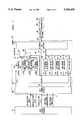
- FIG. 1is a block diagram of a modem embodying the principles of the invention
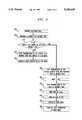
- FIG. 2is a flow diagram of a method embodying the principles of the invention for use in an answering modem
- FIG. 3is a flow diagram of a method embodying the principles of the invention for use in an originating modem.
- FIG. 1shows a modem that embodies the inventive concept.
- the individual components of the data communications systemare well-known and are not described in detail.
- V.32or "208B”
- the signalconforms with the respective well-known specification, e.g., International Cord and Telephone Consultative Committee (CCITT) V.32 , defacto standard Bell System 208B.
- modem 100is connected to telephone network 200, via telephone line 101.
- modem 300is connected to telephone network 200 via telephone line 301.
- the PSTN, or communications channelis represented by telephone lines 101 and 301, and telephone network 200.
- Telephone lines 101 and 301are representative of typical "tip/ring,” or local loop, access provided by telephone network 200. Either modem 100 or modem 300 can place a telephone call to another modem by going "off-hook" and following standard dialing procedures.
- Modem 100comprises data transmitter 160, V.32 answer tone generator 145, 208B answer tone generator 140, V.32 signal AA generator 165, multiplexer 150, V.32 answer tone detector 135, 208B answer tone detector 180, 208B holding tone detector 125, V.32 signal AA detector 120, telephone line interface 170, data receiver 130, data terminal interface 105 and controller 110.
- Both modems 100 and 300are connected to data terminal equipment DTE 50 and DTE 450 via interfaces 51 and 451, respectively. Both of these interfaces represent a collection of signals as specified in Electronic Industry Association (EIA) standard RS-232, which is a representative standard for interconnecting data terminal equipment to data communications equipment, e.g., DTE 50 to modem 100.
- EIAElectronic Industry Association
- a subset of these signalsis shown within interface 51. Since this invention relates to the initial phase of establishing the data connection, other circuitry that is required for maintaining a data connection in either V.32 mode or 208B mode has not been shown. For example, during a 208B mode data connection, a holding tone of 600 Hz is typically provided by the answering modem when the data connection is idle.
- modem 300is the originating modem and places a telephone call to modem 100 through telephone network 200.
- a representative method for processing the incoming telephone call in modem 100is shown in FIG. 2.
- step 505 of FIG. 2telephone line interface 170 of modem 100 answers the telephone call (e.g., by going "off-hook") and provides a signal, which represents that a telephone call has been answered, to controller 110, via lead 172.
- controller 110provides a signal on lead 112 to turn on V.32 answer tone generator 145, which provides a V.32 answer tone on lead 146.
- this V.32 answer toneconforms to CCITT V.32 , e.g., it comprises phase reversals and is a 2100 Hz signal, which is applied to multiplexer 150.
- controller 110provides a control signal to multiplexer 150 to select the signal from V.32 answer tone generator 145 and provide it to telephone line interface 170.
- the latterapplies the V.32 answer tone to telephone line 101 for transmission to modem 300.
- controller 110waits for four seconds for the detection of V.32 signal AA in step 5 15.
- This signal AAhas a frequency of 1800 Hz and is a pan of the V.32 call establishment standard.
- a waiting period of four secondsis useful to take into account the possibility that the call from the originating modem is being performed manually and that a "late connection" may occur.
- a late connectionis one where the originating modem does not receive at least one second of answer tone. This may happen when a person manually dials a telephone (not shown) that is associated with modem 300 to initiate the data call, and delays in depressing the associated "data call” button. The latter switches the received answer tone from modem 100 to apply it to modem 300.
- the incoming signal to modem 100 from modem 300is received by telephone line interface 170 and applied to V.32 signal AA detector 120. It should be noted that this signal is also applied to 208B holding tone detector 125, V.32 answer tone detector 135 and 208B answer tone detector 180. However, it is not expected that these other detectors will detect their respective signal type when modem 100 is the answering modem. Therefore, for simplicity, these other detectors will be ignored in describing the answering procedure for modem 100. In practice, if a signal is detected by one of these other detectors a respective error condition could be recognized by controller 110 and suitable action taken. Also, since the data connection has not yet been established, controller 110 disables data receiver 130 via a signal on lead 116.
- V.32 signal AA detector 120When V.32 signal AA detector 120 detects a signal representative of V.32 signal AA, it signals controller 110 via a signal on lead 121. Controller 110 then turns off V.32 answer tone generator 145, via a signal on lead 112, and switches to V.32 mode in step 520. At this point, controller 110 completes the CCITT V.32 call establishment sequence that includes modem handshaking and training to establish the data connection with modem 300 with the appropriate modulation in step 525.
- controller 110determines whether there is no detection of V.32 signal AA in step 515. If there is no detection of V.32 signal AA in step 515, then controller 110, after waiting the four seconds, proceeds to step 530. In the latter step, controller 110 turns off V.32 answer tone generator 145, via a signal on lead 112, and turns on 208B answer tone generator 140, via a signal on lead 113. In addition, controller 110 applies a control signal to multiplexer 150, which switches the output signal of multiplexer 150 from the output signal of V.32 answer tone generator 145 to the 208B answer tone provided by 208B answer tone generator 140, via lead 141. This answer tone is then applied to telephone line interface 170 for transmission to modem 300 as described above.
- controller 110While the 208B answer tone is being transmitted, controller 110 waits for two seconds in step 535. After transmitting a 208B compatible answer tone for 2 seconds, controller 110, in step 540, turns off 208B answer tone generator 140 and applies a control signal to multiplexer 150 so that its selected input signal is now switched back to the output of V.32 answer tone generator 145, which has been turned off in step 530. At this point, multiplexer 150 applies no signal to telephone line interface 170 so that a period of silence for at least 63 milli-seconds (msec.) is created in step 545. During this period of silence the communications channel between modem 100 and modem 300 is idle.
- msec.milli-seconds
- controller 110turns data set ready (DSR) of interface 51 to the ON state via a signal on lead 109 in step 550. It is assumed that the ON state conforms to the appropriate signal levels in EIA RS-232 representing an active state.
- the DSR signalindicates to DTE 50 that a data connection is established and that modem 100 is "ready.”
- controller 110enters 208B mode, and, in step 560, completes the data connection to modem 300 in 208B mode. It should be noted that although modem 100 does not formally enter 208B mode until step 555 of FIG. 2, it can be observed from FIG. 2 that modem 100 effectively enters a 208B mode of operation once modem 100 determines in step 515 that there was no detection of V.32 signal AA.
- the transmission of an answer tone by modem 100 in step 530should be continuous. In other words, there should be little, if no, silent period between turning off the V.32 answer tone and turning on the 208B answer tone but rather this should be a smooth transition. This is a result of observing the fact that some existing 208B modems will erroneously detect the 2100 Hz V.32 answer tone as a 208B signal. Consequently, if this situation occurs, the presence of a silent interval will cause the originating 208B to be out-of-sequence in the hand-shaking process to establish the data connection. This may result in either the originating modem beginning to transfer data before the answering modem is ready; or the originating modem may become confused upon subsequent detection of the 208B answer tone and fail to establish the data connection.
- modem 100places a telephone call to modem 300 as is known in the prior art.
- modem 100sets a time-out counter in step 610. It is assumed this time-out corresponds to an interrupt service routine as is illustrated by step 615. If the time-out counter expires before it is cleared (discussed below), modem 100 disconnects the telephone call in step 620.
- a typical value for the time-out counteris a number that represents a time delay of 60 seconds.
- modem 100waits to see which of three possible return signals it may receive from modem 300 in step 625.
- This return signalis received by telephone line interface 170 and applied in parallel to V.32 signal AA detector 120, 208B holding tone detector 125, V.32 answer tone detector 135 and 208B answer tone detector 180. Since the data connection has not yet been established, controller 110 disables data receiver 130 via a signal on lead 116. It should also be noted that although the return signal is applied to V.32 signal AA detector, it is not expected in the call origination process that the return signal will be a V.32 signal AA. Therefore V.32 signal AA detector 120 will be ignored in the following description of the origination procedure for modem 100. In practice, if a signal is detected by V.32 signal AA detector 120, a respective error condition could be recognized by controller 110.
- controller 110When a 2021 Hz 208B signal is detected by 208B answer tone detector 180, it signals controller 110 via a signal on lead 181 to go to step 630. Controller 110 then waits for the end of the 2021 Hz 208B signal and for an additional period of 75 msec., and then switches DSR, of interface 51, ON. Then, in step 660, controller 110 enters 208B mode, clears the time-out counter, and completes the data connection as in the prior art.
- V.32 answer tone detector 135if a 2100 Hz V.32 signal is detected in step 625 by V.32 answer tone detector 135, it signals controller 110 via a signal on lead 136 to go to step 640. In the latter step, controller 110 enables V32 signal AA generator 165 to provide V.32 signal AA to multiplexer 150. The latter, via a control signal on lead 149 from controller 110, provides V.32 signal AA to telephone line interface 170. Upon transmission of the V.32 signal AA, controller 110 enters V.32 mode in step 650, clears the time-out counter and in accordance with V.32 specifications completes the data connection to modem 300.
- controller 110switches to 208B mode in step 660, clears the time-out counter, and completes the data connection to modem 300 in accordance with 208B specifications.
- a holding tonemay be detected if a "late connect" has occurred during a manual dialing procedure as described above.
- modem 100 in either originating, or answering, a data callautomodes between a V.32 compatible mode and a 208B compatible mode of operation.
- this automode operationswitches between a full-duplex mode of operation and a half-duplex mode of operation.
- the V.32 mode of operationprovides a full-duplex signalling scheme at a bit rate of 9600 bits/sec.
- the 208B modeprovides a half-duplex signalling scheme at 4800 bits per sec.
- there is more to establishing a data connectionthen just getting the originating modem and the answering modem to pass signals between them.
- the DTE equipment that is coupled to the data communications equipmente.g., DTE 50 to modem 100
- DTE 50 to modem 100must be able to support, in some way, the corresponding mode of operation established between the modems.
- many types of data terminal equipmentcan function correctly in half-duplex mode while the modem to which it is connected is operating in full duplex mode.
- modem 100must simulate half-duplex operation.
- the ability of a V.32 modem to simulate half-duplex operation over a full-duplex data connectionis well-known.
- This type of configurationcan be specified during the administration of modem options by the user. For example, at installation of modem 100, the user configures either through a type of interface, or via hardware straps on the modem itself, that when modem 100 is in V.32 mode it must simulate half-duplex operation.
- DTE 50While even simulated half-duplex operation will provide an increase in data throughput over half-duplex operation, it would be preferable if DTE 50 also supports full-duplex operation. However, if DTE 50 is capable of supporting either full-duplex or half-duplex operation, the user may still have to manually configure DTE 50 to the appropriate setting before even attempting to establish a data connection between modem 100 and modem 300. Therefore, in accordance with a feature of the invention, the EIA RS-232 signal leads are used by the DCE equipment, i.e., modem 100, to signal the DTE equipment whether or not the established data connection is a half-duplex or a full-duplex data connection.
- the DCE equipmenti.e., modem 100
- modem 100manipulates EIA RS-232 signals clear to send (CTS) and DSR to allow DTE 50 to detect in which mode modem 100 connected, i.e., half-duplex or full-duplex.
- CTSclear to send
- the following manipulation of the EIA signal leadsis used to signal DTE 50 as to the operating mode of modem 100.
- signal DSRis switched ON by modem 100 in the process of completing the data connection in either half-duplex mode or full-duplex mode.
- DTE 50switches signal request to send (RTS) ON whenever DTE 50 wants to send data to modem 100. If the data connection is in half-duplex mode, modem 100 switches signal CTS ON when DTE 50 switches signal RTS ON as in the prior art.
- modem 100switches signal CTS ON simultaneously with signal DSR.
- the RTS signal from DTE 50is ignored.
- DTE 50can thus determine that modem 100 is in full-duplex mode because signal RTS is OFF yet signal CTS is ON.
- modem 100can also signal a simulated half duplex mode when DTE 50 switches signal RTS ON. This is accomplished by modem 100 thereafter switching line signal detect (LSD) OFF and switching signal CTS ON within 2 msec.
- LSDline signal detect
- an answer tonei.e., a single frequency signal
- the above-mentioned standardsmay define an answer tone as a narrow frequency band that is centered about, or includes, the above-mentioned frequencies.
- a modemmay generate a tone at 2099 Hz that is an acceptable V.32 answer tone even though a V.32 answer tone was described above as 2100 Hz.
Landscapes
- Engineering & Computer Science (AREA)
- Signal Processing (AREA)
- Computer Networks & Wireless Communication (AREA)
- Telephonic Communication Services (AREA)
- Communication Control (AREA)
Abstract
Description
Claims (13)
Priority Applications (1)
| Application Number | Priority Date | Filing Date | Title |
|---|---|---|---|
| US07/978,536US5349635A (en) | 1992-11-19 | 1992-11-19 | Half-duplex or full-duplex automode operation for use in data communications equipment |
Applications Claiming Priority (1)
| Application Number | Priority Date | Filing Date | Title |
|---|---|---|---|
| US07/978,536US5349635A (en) | 1992-11-19 | 1992-11-19 | Half-duplex or full-duplex automode operation for use in data communications equipment |
Publications (1)
| Publication Number | Publication Date |
|---|---|
| US5349635Atrue US5349635A (en) | 1994-09-20 |
Family
ID=25526186
Family Applications (1)
| Application Number | Title | Priority Date | Filing Date |
|---|---|---|---|
| US07/978,536Expired - LifetimeUS5349635A (en) | 1992-11-19 | 1992-11-19 | Half-duplex or full-duplex automode operation for use in data communications equipment |
Country Status (1)
| Country | Link |
|---|---|
| US (1) | US5349635A (en) |
Cited By (52)
| Publication number | Priority date | Publication date | Assignee | Title |
|---|---|---|---|---|
| WO1995020272A1 (en)* | 1994-01-24 | 1995-07-27 | CODEX COPORATION, a subsidiary company of MOTOROLA INC | Adaptive coherent signal detection method and apparatus |
| US5513213A (en)* | 1993-10-04 | 1996-04-30 | At&T Corp. | Data-driven autorating for use in data communications |
| WO1996019047A1 (en)* | 1994-12-14 | 1996-06-20 | Motorola Inc. | Signalling techniques and device for high speed data transmission over voiceband channels |
| US5550881A (en)* | 1995-04-13 | 1996-08-27 | Motorola, Inc. | Automatic modulation mode selecting unit and method for modems |
| US5561666A (en)* | 1995-03-06 | 1996-10-01 | International Business Machines Corporation | Apparatus and method for determining operational mode for a station entering a network |
| US5592538A (en)* | 1993-03-10 | 1997-01-07 | Momentum, Inc. | Telecommunication device and method for interactive voice and data |
| WO1997016000A1 (en)* | 1995-10-26 | 1997-05-01 | Omnipoint Corporation | Coexisting communication systems |
| US5633890A (en)* | 1994-02-24 | 1997-05-27 | Ricoh Company, Ltd. | Method for intelligent data terminal equipment (DTE) data communication |
| US5636037A (en)* | 1992-04-01 | 1997-06-03 | Ricoh Company, Ltd. | Modem unit |
| US5675641A (en)* | 1996-05-06 | 1997-10-07 | Sony Corporation | Dual-mode speaker telephone |
| USD396044S (en) | 1997-03-04 | 1998-07-14 | Northrop Grumman Corporation | Modem |
| US5787116A (en)* | 1996-06-18 | 1998-07-28 | Motorola Inc. | Apparatus and method for detecting amplitude modulated answer back toned signals |
| US5809085A (en)* | 1995-06-28 | 1998-09-15 | Motorola Inc. | Apparatus and method for detecting and discriminating various signal types in the presence of impulse distortions |
| US5918024A (en)* | 1996-05-08 | 1999-06-29 | Ericsson, Inc. | Method and apparatus for providing single channel communications |
| US5940438A (en)* | 1997-02-18 | 1999-08-17 | Mitsubishi Electric Information Technology Center America, Inc (Ita) | Universal modem for digital video, audio and data communications |
| US5943364A (en)* | 1995-02-16 | 1999-08-24 | Canon Kabushiki Kaisha | Data communication apparatus for setting bit rate according to line quality |
| US5959979A (en)* | 1997-05-05 | 1999-09-28 | Northrop Grumman Corporation | Half-duplex communication system for telemetry modems |
| WO2000041354A1 (en)* | 1999-01-08 | 2000-07-13 | Matsushita Graphic Communication Systems, Inc. | ACTIVATION OF MULTIPLE xDSL MODEMS WITH HALF DUPLEX AND FULL DUPLEX PROCEDURES |
| US6385483B1 (en) | 1994-09-21 | 2002-05-07 | Medrad, Inc. | Patient specific dosing contrast delivery systems and methods |
| WO2001091442A3 (en)* | 2000-05-23 | 2002-05-23 | L 3 Comm Corp | Multimode modem with automatic negotiation of operational mode |
| US20020094071A1 (en)* | 1999-07-13 | 2002-07-18 | Norimasa Niiya | Key telephone system and interface unit for key telephone |
| US6567463B1 (en)* | 1998-05-29 | 2003-05-20 | 3Com Corporation | Method and system for detecting analog and ADPCM links in a communication channel |
| US6639911B1 (en)* | 1998-03-31 | 2003-10-28 | Texas Instruments Incorporated | Data communications system with splitterless operation |
| US20030224825A1 (en)* | 2002-06-03 | 2003-12-04 | Cox Gregory W. | Method and apparatus for interactive communication between half-duplex and full-duplex systems |
| US20040027998A1 (en)* | 1999-01-08 | 2004-02-12 | Panasonic Communications Co., Ltd. | Activation of multiple xDSL modems with half duplex and full duplex procedures |
| US6694470B1 (en) | 1999-05-21 | 2004-02-17 | Panasonic Communications Co., Ltd. | Retransmission procedure and apparatus for handshaking protocol |
| US20040052308A1 (en)* | 1998-04-01 | 2004-03-18 | Panasonic Communications Co., Ltd. | Activation of multiple xDSL modems with implicit channel probe |
| US6735245B1 (en) | 1998-01-09 | 2004-05-11 | Panasonic Communications Co., Ltd. | Activation of multiple XDSL modems with channel probe |
| US6751254B1 (en) | 1999-05-05 | 2004-06-15 | Panasonic Communications Co., Ltd. | Activation of multiple xDSL modems with power control measurement |
| US6788651B1 (en)* | 1999-04-21 | 2004-09-07 | Mindspeed Technologies, Inc. | Methods and apparatus for data communications on packet networks |
| US20060025165A1 (en)* | 2004-07-31 | 2006-02-02 | Nextel Communications, Inc. | Wireless communication system providing seamless switching between full-duplex and half-duplex modes |
| US20070274296A1 (en)* | 2006-05-10 | 2007-11-29 | Cross Charles W Jr | Voip barge-in support for half-duplex dsr client on a full-duplex network |
| US20070282263A1 (en)* | 2004-11-24 | 2007-12-06 | Medrad, Inc. | Devices, systems and methods for determining parameters of one or more phases of an injection procedure |
| US20090042622A1 (en)* | 2007-08-06 | 2009-02-12 | Mspot, Inc. | Method and apparatus for creating, using, and disseminating customized audio/video clips |
| CN102045674A (en)* | 2009-10-22 | 2011-05-04 | 通用汽车有限责任公司 | Modem signaling with multi-tone prefix on voice channel of wireless communication system |
| US9008759B2 (en) | 2007-07-17 | 2015-04-14 | Bayer Medical Care Inc. | Devices and systems for determination of parameters for a procedure, for estimation of cardiopulmonary function and for fluid delivery |
| US9302044B2 (en) | 2006-12-29 | 2016-04-05 | Bayer Healthcare Llc | Patient-based parameter generation systems for medical injection procedures |
| US9421330B2 (en) | 2008-11-03 | 2016-08-23 | Bayer Healthcare Llc | Mitigation of contrast-induced nephropathy |
| US9616166B2 (en) | 2004-11-16 | 2017-04-11 | Bayer Healthcare Llc | Systems and methods of determining injection protocols for diagnostic imaging procedures |
| US9949704B2 (en) | 2012-05-14 | 2018-04-24 | Bayer Healthcare Llc | Systems and methods for determination of pharmaceutical fluid injection protocols based on x-ray tube voltage |
| US9959389B2 (en) | 2010-06-24 | 2018-05-01 | Bayer Healthcare Llc | Modeling of pharmaceutical propagation and parameter generation for injection protocols |
| US10898638B2 (en) | 2016-03-03 | 2021-01-26 | Bayer Healthcare Llc | System and method for improved fluid delivery in multi-fluid injector systems |
| US11141535B2 (en) | 2017-08-31 | 2021-10-12 | Bayer Healthcare Llc | Fluid path impedance assessment for improving fluid delivery performance |
| US11278853B2 (en) | 2013-03-13 | 2022-03-22 | Bayer Healthcare Llc | Method for controlling fluid accuracy and backflow compensation |
| US11478581B2 (en) | 2017-08-31 | 2022-10-25 | Bayer Healthcare Llc | Fluid injector system volume compensation system and method |
| US11598664B2 (en) | 2017-08-31 | 2023-03-07 | Bayer Healthcare Llc | Injector pressure calibration system and method |
| US11779702B2 (en) | 2017-08-31 | 2023-10-10 | Bayer Healthcare Llc | Method for dynamic pressure control in a fluid injector system |
| US11786652B2 (en) | 2017-08-31 | 2023-10-17 | Bayer Healthcare Llc | System and method for drive member position and fluid injector system mechanical calibration |
| US12208239B2 (en) | 2018-08-28 | 2025-01-28 | Bayer Healthcare Llc | Fluid injector system, method of preventing fluid backflow, and computer program product |
| US12251544B2 (en) | 2018-04-19 | 2025-03-18 | Bayer Healthcare Llc | System and method for air detection in fluid injector |
| US12263326B2 (en) | 2016-11-14 | 2025-04-01 | Bayer Healthcare Llc | Methods and systems for verifying the contents of a syringe used for medical fluid delivery |
| US12427249B2 (en) | 2018-08-28 | 2025-09-30 | Bayer Healthcare Llc | Fluid injector system with improved ratio performance |
Citations (6)
| Publication number | Priority date | Publication date | Assignee | Title |
|---|---|---|---|---|
| US4215243A (en)* | 1978-11-17 | 1980-07-29 | Racal-Vadic Inc. | Automatic modem identification system |
| US4471489A (en)* | 1981-03-19 | 1984-09-11 | General Datacomm Industries, Inc. | Automatic answer/originate mode selection in modem |
| US4599719A (en)* | 1984-06-18 | 1986-07-08 | At&T Information Systems Inc. | Full duplex data set with half-duplex emulation |
| US4680773A (en)* | 1985-10-30 | 1987-07-14 | Microcom, Inc. | Data telecommunications system and method utilizing a multi-mode modem |
| US4782498A (en)* | 1986-08-28 | 1988-11-01 | Hayes Microcomputer Products, Inc. | Modem with improved handshaking capability |
| US4931250A (en)* | 1988-05-12 | 1990-06-05 | Codex Corporation | Multimode modem |
- 1992
- 1992-11-19USUS07/978,536patent/US5349635A/ennot_activeExpired - Lifetime
Patent Citations (6)
| Publication number | Priority date | Publication date | Assignee | Title |
|---|---|---|---|---|
| US4215243A (en)* | 1978-11-17 | 1980-07-29 | Racal-Vadic Inc. | Automatic modem identification system |
| US4471489A (en)* | 1981-03-19 | 1984-09-11 | General Datacomm Industries, Inc. | Automatic answer/originate mode selection in modem |
| US4599719A (en)* | 1984-06-18 | 1986-07-08 | At&T Information Systems Inc. | Full duplex data set with half-duplex emulation |
| US4680773A (en)* | 1985-10-30 | 1987-07-14 | Microcom, Inc. | Data telecommunications system and method utilizing a multi-mode modem |
| US4782498A (en)* | 1986-08-28 | 1988-11-01 | Hayes Microcomputer Products, Inc. | Modem with improved handshaking capability |
| US4931250A (en)* | 1988-05-12 | 1990-06-05 | Codex Corporation | Multimode modem |
Non-Patent Citations (6)
| Title |
|---|
| Advertisement, "Motor Mouth." -Racal-Vadic, The Dial-Up Authority, Network World, Nov. 12, 1990. |
| Advertisement, Motor Mouth. Racal Vadic, The Dial Up Authority, Network World, Nov. 12, 1990.* |
| Affidavit by Richard E. McCartney, Largo, Fla.* |
| Annex A to Recommendation V. 32 bis.* |
| Manual pages for Racal Vadic 9642PA, pp. 2 23, 2 24.* |
| Manual pages for Racal-Vadic 9642PA, pp. 2-23, 2-24. |
Cited By (109)
| Publication number | Priority date | Publication date | Assignee | Title |
|---|---|---|---|---|
| US5636037A (en)* | 1992-04-01 | 1997-06-03 | Ricoh Company, Ltd. | Modem unit |
| US5592538A (en)* | 1993-03-10 | 1997-01-07 | Momentum, Inc. | Telecommunication device and method for interactive voice and data |
| US5513213A (en)* | 1993-10-04 | 1996-04-30 | At&T Corp. | Data-driven autorating for use in data communications |
| US5446771A (en)* | 1994-01-24 | 1995-08-29 | Motorola, Inc. | Adaptive coherent signal detection method and apparatus |
| WO1995020272A1 (en)* | 1994-01-24 | 1995-07-27 | CODEX COPORATION, a subsidiary company of MOTOROLA INC | Adaptive coherent signal detection method and apparatus |
| AU691240B2 (en)* | 1994-01-24 | 1998-05-14 | Motorola, Inc. | Adaptive coherent signal detection method and apparatus |
| US5633890A (en)* | 1994-02-24 | 1997-05-27 | Ricoh Company, Ltd. | Method for intelligent data terminal equipment (DTE) data communication |
| US6385483B1 (en) | 1994-09-21 | 2002-05-07 | Medrad, Inc. | Patient specific dosing contrast delivery systems and methods |
| US5732104A (en)* | 1994-12-14 | 1998-03-24 | Motorola, Inc. | Signalling techniques and device for high speed data transmission over voiceband channels |
| WO1996019047A1 (en)* | 1994-12-14 | 1996-06-20 | Motorola Inc. | Signalling techniques and device for high speed data transmission over voiceband channels |
| CN1109412C (en)* | 1994-12-14 | 2003-05-21 | 摩托罗拉公司 | Signaling method and apparatus for high-speed data transmission over a voice-band channel |
| AU692628B2 (en)* | 1994-12-14 | 1998-06-11 | Google Technology Holdings LLC | Signalling techniques and device for high speed data transmission over voiceband channels |
| US5943364A (en)* | 1995-02-16 | 1999-08-24 | Canon Kabushiki Kaisha | Data communication apparatus for setting bit rate according to line quality |
| US5561666A (en)* | 1995-03-06 | 1996-10-01 | International Business Machines Corporation | Apparatus and method for determining operational mode for a station entering a network |
| WO1996032795A1 (en)* | 1995-04-13 | 1996-10-17 | Motorola Inc. | Automatic modulation mode selecting unit and method for modems |
| AU679654B2 (en)* | 1995-04-13 | 1997-07-03 | Motorola, Inc. | Automatic modulation mode selecting unit and method for modems |
| US5550881A (en)* | 1995-04-13 | 1996-08-27 | Motorola, Inc. | Automatic modulation mode selecting unit and method for modems |
| US5809085A (en)* | 1995-06-28 | 1998-09-15 | Motorola Inc. | Apparatus and method for detecting and discriminating various signal types in the presence of impulse distortions |
| WO1997016000A1 (en)* | 1995-10-26 | 1997-05-01 | Omnipoint Corporation | Coexisting communication systems |
| US5732076A (en)* | 1995-10-26 | 1998-03-24 | Omnipoint Corporation | Coexisting communication systems |
| US5675641A (en)* | 1996-05-06 | 1997-10-07 | Sony Corporation | Dual-mode speaker telephone |
| US5918024A (en)* | 1996-05-08 | 1999-06-29 | Ericsson, Inc. | Method and apparatus for providing single channel communications |
| USRE40346E1 (en)* | 1996-05-08 | 2008-05-27 | Telefonaktiebolaget Lm Ericsson (Publ) | Method and apparatus for providing single channel communications |
| US5787116A (en)* | 1996-06-18 | 1998-07-28 | Motorola Inc. | Apparatus and method for detecting amplitude modulated answer back toned signals |
| US5940438A (en)* | 1997-02-18 | 1999-08-17 | Mitsubishi Electric Information Technology Center America, Inc (Ita) | Universal modem for digital video, audio and data communications |
| US6671328B1 (en) | 1997-02-18 | 2003-12-30 | Mitsubishi Electric Research Laboratories, Inc. | Generating signals having different modulation formats |
| USD396044S (en) | 1997-03-04 | 1998-07-14 | Northrop Grumman Corporation | Modem |
| US5959979A (en)* | 1997-05-05 | 1999-09-28 | Northrop Grumman Corporation | Half-duplex communication system for telemetry modems |
| US6735245B1 (en) | 1998-01-09 | 2004-05-11 | Panasonic Communications Co., Ltd. | Activation of multiple XDSL modems with channel probe |
| US6639911B1 (en)* | 1998-03-31 | 2003-10-28 | Texas Instruments Incorporated | Data communications system with splitterless operation |
| US6768772B2 (en) | 1998-04-01 | 2004-07-27 | Panasonic Communications Co., Ltd. | Activation of multiple xDSL modems with implicit channel probe |
| US20040052308A1 (en)* | 1998-04-01 | 2004-03-18 | Panasonic Communications Co., Ltd. | Activation of multiple xDSL modems with implicit channel probe |
| US6765957B2 (en) | 1998-04-01 | 2004-07-20 | Panasonic Communications Co., Ltd. | Activation of multiple xDSL modems with implicit channel probe |
| US7508867B2 (en) | 1998-04-01 | 2009-03-24 | Panasonic Communications Co., Ltd. | Activation of multiple xDSL modems with implicit channel probe |
| US20050129103A1 (en)* | 1998-04-01 | 2005-06-16 | Panasonic Communications Co., Ltd. | Activation of multiple xDSL modems with implicit channel probe |
| US6873652B1 (en) | 1998-04-01 | 2005-03-29 | Panasonic Communications Co., Ltd. | Activation of multiple xDSL modems with implicit channel probe |
| US6934326B2 (en) | 1998-04-01 | 2005-08-23 | Panasonic Communications Co., Ltd | Activation of multiple xDSL modems with implicit channel probe |
| US7272173B2 (en) | 1998-04-01 | 2007-09-18 | Panasonic Communications Co., Ltd. | Activation of multiple xDSL modems with implicit channel probe |
| US20040057510A1 (en)* | 1998-04-01 | 2004-03-25 | Panasonic Communications Co., Ltd. | Activation of multiple xDSL modems with implicit channel probe |
| US6952442B2 (en) | 1998-04-01 | 2005-10-04 | Panasonic Communications Co., Ltd. | Activation of multiple xDSL modems with implicit channel probe |
| US20040179552A1 (en)* | 1998-04-01 | 2004-09-16 | Panasonic Communications Co., Ltd. | Activation of multiple xDSL modems with implicit channel probe |
| US6987802B2 (en) | 1998-04-01 | 2006-01-17 | Panasonic Communications Co., Ltd. | Activation of multiple XDSL modems with implicit channel probe |
| US7012954B2 (en) | 1998-04-01 | 2006-03-14 | Panasonic Communications Co., Ltd | Activation of multiple xDSL modems with implicit channel probe |
| US6567463B1 (en)* | 1998-05-29 | 2003-05-20 | 3Com Corporation | Method and system for detecting analog and ADPCM links in a communication channel |
| US6999506B2 (en) | 1999-01-08 | 2006-02-14 | Panasonic Communications Co., Ltd. | Activation of multiple xDSL modems with half duplex and full duplex procedures |
| US20040131111A1 (en)* | 1999-01-08 | 2004-07-08 | Panasonic Communications Co., Ltd | Activation of multiple xDSL modems with half duplex and full duplex procedures |
| US7058123B2 (en)* | 1999-01-08 | 2006-06-06 | Panasonic Communications Co., Ltd. | Activation of multiple xDSL modems with half duplex and full duplex procedures |
| JP3431600B2 (en) | 1999-01-08 | 2003-07-28 | パナソニック コミュニケーションズ株式会社 | Activation of multiple xDSL modems by half-duplex and full-duplex procedures |
| WO2000041354A1 (en)* | 1999-01-08 | 2000-07-13 | Matsushita Graphic Communication Systems, Inc. | ACTIVATION OF MULTIPLE xDSL MODEMS WITH HALF DUPLEX AND FULL DUPLEX PROCEDURES |
| EP1422918A3 (en)* | 1999-01-08 | 2006-03-29 | Matsushita Graphic Communication Systems, Inc. | Activation of multiple xDSL modems with half duplex and full duplex procedures |
| US20040027998A1 (en)* | 1999-01-08 | 2004-02-12 | Panasonic Communications Co., Ltd. | Activation of multiple xDSL modems with half duplex and full duplex procedures |
| US6950459B1 (en) | 1999-01-08 | 2005-09-27 | Panasonic Communications Co., Ltd. | Activation of multiple xDSL modems with half duplex and full duplex procedures |
| EP1062761A4 (en)* | 1999-01-08 | 2002-04-24 | Matsushita Graphic Communic | ACTIVATION OF MULTIPLE xDSL MODEMS WITH HALF DUPLEX AND FULL DUPLEX PROCEDURES |
| US20050201294A1 (en)* | 1999-01-08 | 2005-09-15 | Panasonic Communications Co., Ltd. | Activation of multiple xDSL modems with half duplex and full duplex procedures |
| US6788651B1 (en)* | 1999-04-21 | 2004-09-07 | Mindspeed Technologies, Inc. | Methods and apparatus for data communications on packet networks |
| US6990112B1 (en) | 1999-04-21 | 2006-01-24 | Mindspeed Technologies, Inc. | Methods and apparatus for data communications on packet networks |
| US6917647B2 (en) | 1999-05-05 | 2005-07-12 | Panasonic Communications Co., Ltd. | Activation of multiple xDSL modems with power control measurement |
| US20040184520A1 (en)* | 1999-05-05 | 2004-09-23 | Panasonic Communications Co., Ltd. | Activation of multiple xDSL modems with power control measurement |
| US6751254B1 (en) | 1999-05-05 | 2004-06-15 | Panasonic Communications Co., Ltd. | Activation of multiple xDSL modems with power control measurement |
| US6901547B2 (en) | 1999-05-21 | 2005-05-31 | Panasonic Communications Co., Ltd. | Retransmission procedure and apparatus for handshaking protocol |
| US7051258B2 (en) | 1999-05-21 | 2006-05-23 | Panasonic Communications Co., Ltd. | Retransmission procedure and apparatus for handshaking protocol |
| US20040068686A1 (en)* | 1999-05-21 | 2004-04-08 | Panasonic Communications Co., Ltd. | Retransmission procedure and apparatus for handshaking protocol |
| US6694470B1 (en) | 1999-05-21 | 2004-02-17 | Panasonic Communications Co., Ltd. | Retransmission procedure and apparatus for handshaking protocol |
| US20020094071A1 (en)* | 1999-07-13 | 2002-07-18 | Norimasa Niiya | Key telephone system and interface unit for key telephone |
| US6978000B2 (en)* | 1999-07-13 | 2005-12-20 | Kabushiki Kaisha Toshiba | Key telephone system and interface unit for key telephone |
| WO2001091442A3 (en)* | 2000-05-23 | 2002-05-23 | L 3 Comm Corp | Multimode modem with automatic negotiation of operational mode |
| US20040170222A1 (en)* | 2000-05-23 | 2004-09-02 | L-3 Communications Corporation | Multimode modem with automatic negotiation of operational mode |
| US6768771B1 (en) | 2000-05-23 | 2004-07-27 | L3-Communications Corporation | Multimode modem with automatic negotiation of operational mode |
| US7313103B2 (en)* | 2002-06-03 | 2007-12-25 | Motorola, Inc. | Method and apparatus for interactive communication between half-duplex and full-duplex systems |
| US20030224825A1 (en)* | 2002-06-03 | 2003-12-04 | Cox Gregory W. | Method and apparatus for interactive communication between half-duplex and full-duplex systems |
| US7415282B2 (en)* | 2004-07-31 | 2008-08-19 | Nextel Communications Inc. | Wireless communication system providing seamless switching between full-duplex and half-duplex modes |
| US20060025165A1 (en)* | 2004-07-31 | 2006-02-02 | Nextel Communications, Inc. | Wireless communication system providing seamless switching between full-duplex and half-duplex modes |
| US9616166B2 (en) | 2004-11-16 | 2017-04-11 | Bayer Healthcare Llc | Systems and methods of determining injection protocols for diagnostic imaging procedures |
| US20070282263A1 (en)* | 2004-11-24 | 2007-12-06 | Medrad, Inc. | Devices, systems and methods for determining parameters of one or more phases of an injection procedure |
| US10166326B2 (en) | 2004-11-24 | 2019-01-01 | Bayer Healthcare Llc | Devices, systems and methods for determining parameters of one or more phases of an injection procedure |
| US9950107B2 (en) | 2004-11-24 | 2018-04-24 | Bayer Healthcare Llc | Systems and methods for managing workflow for injection procedures |
| US9238099B2 (en) | 2004-11-24 | 2016-01-19 | Bayer Healthcare Llc | System and apparatus for modeling pressures generated during an injection procedure |
| US7925330B2 (en) | 2004-11-24 | 2011-04-12 | Medrad, Inc. | Devices, systems and methods for determining parameters of one or more phases of an injection procedure |
| US20070274296A1 (en)* | 2006-05-10 | 2007-11-29 | Cross Charles W Jr | Voip barge-in support for half-duplex dsr client on a full-duplex network |
| US7848314B2 (en)* | 2006-05-10 | 2010-12-07 | Nuance Communications, Inc. | VOIP barge-in support for half-duplex DSR client on a full-duplex network |
| US9302044B2 (en) | 2006-12-29 | 2016-04-05 | Bayer Healthcare Llc | Patient-based parameter generation systems for medical injection procedures |
| US10463782B2 (en) | 2006-12-29 | 2019-11-05 | Bayer Healthcare Llc | Patient-based parameter generation systems for medical injection procedures |
| US9008759B2 (en) | 2007-07-17 | 2015-04-14 | Bayer Medical Care Inc. | Devices and systems for determination of parameters for a procedure, for estimation of cardiopulmonary function and for fluid delivery |
| US8135114B2 (en)* | 2007-08-06 | 2012-03-13 | Mspot, Inc. | Method and apparatus for creating an answer tone for a computing device with phone capabilities or a telephone |
| US9002410B2 (en) | 2007-08-06 | 2015-04-07 | Samsung Electronics Co., Ltd. | Method and apparatus for creating, using, and disseminating customized audio/video clips |
| US20090042622A1 (en)* | 2007-08-06 | 2009-02-12 | Mspot, Inc. | Method and apparatus for creating, using, and disseminating customized audio/video clips |
| US20090041208A1 (en)* | 2007-08-06 | 2009-02-12 | Mspot, Inc. | Method and apparatus for creating an answer tone for a computing device with phone cababilities or a telephone |
| US9421330B2 (en) | 2008-11-03 | 2016-08-23 | Bayer Healthcare Llc | Mitigation of contrast-induced nephropathy |
| CN102045674A (en)* | 2009-10-22 | 2011-05-04 | 通用汽车有限责任公司 | Modem signaling with multi-tone prefix on voice channel of wireless communication system |
| US20110249714A1 (en)* | 2009-10-22 | 2011-10-13 | Gm Global Technology Operations, Inc. | Modem signaling using a multitone prefix over a voice channel of a wireless communication system |
| US9225844B2 (en)* | 2009-10-22 | 2015-12-29 | General Motors Llc | Modem signaling using a multitone prefix over a voice channel of a wireless communication system |
| CN102045674B (en)* | 2009-10-22 | 2015-01-14 | 通用汽车有限责任公司 | Modem signaling with multi-tone prefix on voice channel of wireless communication system |
| US9959389B2 (en) | 2010-06-24 | 2018-05-01 | Bayer Healthcare Llc | Modeling of pharmaceutical propagation and parameter generation for injection protocols |
| US9949704B2 (en) | 2012-05-14 | 2018-04-24 | Bayer Healthcare Llc | Systems and methods for determination of pharmaceutical fluid injection protocols based on x-ray tube voltage |
| US11191501B2 (en) | 2012-05-14 | 2021-12-07 | Bayer Healthcare Llc | Systems and methods for determination of pharmaceutical fluid injection protocols based on x-ray tube voltage |
| US11278853B2 (en) | 2013-03-13 | 2022-03-22 | Bayer Healthcare Llc | Method for controlling fluid accuracy and backflow compensation |
| US11672902B2 (en) | 2016-03-03 | 2023-06-13 | Bayer Healthcare Llc | System and method for improved fluid delivery in multi-fluid injector systems |
| US10898638B2 (en) | 2016-03-03 | 2021-01-26 | Bayer Healthcare Llc | System and method for improved fluid delivery in multi-fluid injector systems |
| US12263326B2 (en) | 2016-11-14 | 2025-04-01 | Bayer Healthcare Llc | Methods and systems for verifying the contents of a syringe used for medical fluid delivery |
| US11141535B2 (en) | 2017-08-31 | 2021-10-12 | Bayer Healthcare Llc | Fluid path impedance assessment for improving fluid delivery performance |
| US11598664B2 (en) | 2017-08-31 | 2023-03-07 | Bayer Healthcare Llc | Injector pressure calibration system and method |
| US11779702B2 (en) | 2017-08-31 | 2023-10-10 | Bayer Healthcare Llc | Method for dynamic pressure control in a fluid injector system |
| US11786652B2 (en) | 2017-08-31 | 2023-10-17 | Bayer Healthcare Llc | System and method for drive member position and fluid injector system mechanical calibration |
| US11826553B2 (en) | 2017-08-31 | 2023-11-28 | Bayer Healthcare Llc | Fluid path impedance assessment for improving fluid delivery performance |
| US12214155B2 (en) | 2017-08-31 | 2025-02-04 | Bayer Healthcare Llc | Fluid injector system volume compensation system and method |
| US11478581B2 (en) | 2017-08-31 | 2022-10-25 | Bayer Healthcare Llc | Fluid injector system volume compensation system and method |
| US12251544B2 (en) | 2018-04-19 | 2025-03-18 | Bayer Healthcare Llc | System and method for air detection in fluid injector |
| US12208239B2 (en) | 2018-08-28 | 2025-01-28 | Bayer Healthcare Llc | Fluid injector system, method of preventing fluid backflow, and computer program product |
| US12427249B2 (en) | 2018-08-28 | 2025-09-30 | Bayer Healthcare Llc | Fluid injector system with improved ratio performance |
Similar Documents
| Publication | Publication Date | Title |
|---|---|---|
| US5349635A (en) | Half-duplex or full-duplex automode operation for use in data communications equipment | |
| CA2094189E (en) | Technique for automatic identification of a remote modem | |
| US5793809A (en) | Transparent technique for Mu-law modems to detect an all-digital circuit connection | |
| EP0631417B1 (en) | Radio telephone system control apparatus and method | |
| US5473675A (en) | Call establishment for simultaneous analog and digital communications | |
| US5513212A (en) | Conversion of a fax modulation to a data modulation | |
| JP3559579B2 (en) | Interface device | |
| US5699414A (en) | Method and apparatus for sharing a single telephone line between a facsimile machine, data modem, telephone answering device, and a person | |
| US5946304A (en) | Method and apparatus for controlling the operation of a modem capable of transmitting and receiving both voice and data signals | |
| US5396486A (en) | Data communications equipment interface leads to signal half-duplex or full-duplex operation | |
| US5440619A (en) | Voice, data and facsimile modem with modified ringback answering | |
| US5123042A (en) | Cordless telephone apparatus which avoids simultaneous connecting unit/cordless telephone call conflicts | |
| US5517550A (en) | ISDN switching apparatus | |
| US6081556A (en) | Transparent technique for Mu-law modems to detect an all-digital circuit connection | |
| US5038373A (en) | Process for determining whether a subscriber is the calling or the called party | |
| KR920004154B1 (en) | Analog/digital communication system | |
| JPS6387068A (en) | Circuit switching device | |
| JPS5839141A (en) | Connection confirming system | |
| JPH03172062A (en) | Facsimile exchange device | |
| JPH04336746A (en) | Facsimile equipment | |
| JPS63236442A (en) | Communication device | |
| JPH05122271A (en) | Line changeover device | |
| JPH0779297A (en) | Terminal adapter device | |
| JPH0371833B2 (en) | ||
| JPH0683249B2 (en) | Modem pool response return method |
Legal Events
| Date | Code | Title | Description |
|---|---|---|---|
| AS | Assignment | Owner name:AMERICAN TELEPHONE AND TELEGRAPH COMPANY, NEW YORK Free format text:ASSIGNMENT OF ASSIGNORS INTEREST.;ASSIGNOR:SCOTT, ROBERT E.;REEL/FRAME:006313/0786 Effective date:19921113 | |
| AS | Assignment | Owner name:PARADYNE CORPORATION (FORMERLY KNOWN AS AT&T PARAD Free format text:ASSIGNMENT OF ASSIGNORS INTEREST;ASSIGNOR:LUCENT TECHNOLOGIES, INC.;REEL/FRAME:008167/0408 Effective date:19960731 | |
| AS | Assignment | Owner name:LUCENT TECHNOLOGIES INC., NEW JERSEY Free format text:ASSIGNMENT OF ASSIGNORS INTEREST;ASSIGNOR:AT&T CORP.;REEL/FRAME:008178/0161 Effective date:19960329 | |
| AS | Assignment | Owner name:BANKAMERICA BUSINESS CREDIT, INC., CALIFORNIA Free format text:SECURITY AGREEMENT;ASSIGNOR:PARADYNE CORPORATION;REEL/FRAME:008261/0384 Effective date:19960731 | |
| AS | Assignment | Owner name:AT&T CORPORATION, NEW JERSEY Free format text:CHANGE OF NAME;ASSIGNOR:AMERICAN TELEPHONE & TELEGRAPH COMPANY;REEL/FRAME:008313/0445 Effective date:19940420 | |
| FEPP | Fee payment procedure | Free format text:PAYOR NUMBER ASSIGNED (ORIGINAL EVENT CODE: ASPN); ENTITY STATUS OF PATENT OWNER: LARGE ENTITY | |
| FPAY | Fee payment | Year of fee payment:4 | |
| SULP | Surcharge for late payment | ||
| AS | Assignment | Owner name:FOOTHILL CAPITAL CORPORATION, CALIFORNIA Free format text:SECURITY AGREEMENT;ASSIGNOR:PARADYNE CORPORATION;REEL/FRAME:012211/0350 Effective date:20010716 | |
| REMI | Maintenance fee reminder mailed | ||
| REIN | Reinstatement after maintenance fee payment confirmed | ||
| FP | Lapsed due to failure to pay maintenance fee | Effective date:20020920 | |
| FEPP | Fee payment procedure | Free format text:PETITION RELATED TO MAINTENANCE FEES FILED (ORIGINAL EVENT CODE: PMFP); ENTITY STATUS OF PATENT OWNER: LARGE ENTITY | |
| FEPP | Fee payment procedure | Free format text:PETITION RELATED TO MAINTENANCE FEES GRANTED (ORIGINAL EVENT CODE: PMFG); ENTITY STATUS OF PATENT OWNER: LARGE ENTITY | |
| FPAY | Fee payment | Year of fee payment:8 | |
| SULP | Surcharge for late payment | ||
| PRDP | Patent reinstated due to the acceptance of a late maintenance fee | Effective date:20040212 | |
| STCF | Information on status: patent grant | Free format text:PATENTED CASE | |
| REMI | Maintenance fee reminder mailed | ||
| FPAY | Fee payment | Year of fee payment:12 | |
| SULP | Surcharge for late payment | Year of fee payment:11 | |
| AS | Assignment | Owner name:PARADYNE CORPORATION, FLORIDA Free format text:RELEASE BY SECURED PARTY;ASSIGNORS:BANK OF AMERICA, N.A.;BANKAMERICA BUSINESS CREDIT, INC.;REEL/FRAME:027846/0117 Effective date:20040722 Owner name:PARADYNE CORPORATION, FLORIDA Free format text:RELEASE BY SECURED PARTY;ASSIGNOR:WELLS FARGO FOOTHILL, INC., F/K/A FOOTHILL CAPITAL CORPORATION;REEL/FRAME:027844/0446 Effective date:20041216 | |
| AS | Assignment | Owner name:WELLS FARGO BANK, NATIONAL ASSOCIATION, CALIFORNIA Free format text:PATENT AND TRADEMARK SECURITY AGREEMENT;ASSIGNOR:PARADYNE CORPORATION;REEL/FRAME:028115/0393 Effective date:20120313 | |
| AS | Assignment | Owner name:PARADYNE CORPORATION, CALIFORNIA Free format text:RELEASE BY SECURED PARTY;ASSIGNOR:WELLS FARGO BANK, NATIONAL ASSOCIATION;REEL/FRAME:049983/0856 Effective date:20190227 |