US5349364A - Electromagnetic power distribution system comprising distinct type couplers - Google Patents
Electromagnetic power distribution system comprising distinct type couplersDownload PDFInfo
- Publication number
- US5349364A US5349364AUS07/904,597US90459792AUS5349364AUS 5349364 AUS5349364 AUS 5349364AUS 90459792 AUS90459792 AUS 90459792AUS 5349364 AUS5349364 AUS 5349364A
- Authority
- US
- United States
- Prior art keywords
- couplers
- coupler
- assemblies
- electromagnetic power
- row
- Prior art date
- Legal status (The legal status is an assumption and is not a legal conclusion. Google has not performed a legal analysis and makes no representation as to the accuracy of the status listed.)
- Expired - Lifetime
Links
- 230000000712assemblyEffects0.000claimsabstractdescription49
- 238000000429assemblyMethods0.000claimsabstractdescription49
- 239000004020conductorSubstances0.000claimsabstractdescription40
- 230000005540biological transmissionEffects0.000claimsabstractdescription15
- 230000010363phase shiftEffects0.000claimsdescription28
- 230000001902propagating effectEffects0.000claimsdescription5
- 230000005855radiationEffects0.000abstractdescription8
- 238000010276constructionMethods0.000description3
- 230000008878couplingEffects0.000description3
- 238000010168coupling processMethods0.000description3
- 238000005859coupling reactionMethods0.000description3
- 238000009825accumulationMethods0.000description2
- 230000015572biosynthetic processEffects0.000description2
- RYGMFSIKBFXOCR-UHFFFAOYSA-NCopperChemical compound[Cu]RYGMFSIKBFXOCR-UHFFFAOYSA-N0.000description1
- 229910052782aluminiumInorganic materials0.000description1
- XAGFODPZIPBFFR-UHFFFAOYSA-NaluminiumChemical compound[Al]XAGFODPZIPBFFR-UHFFFAOYSA-N0.000description1
- PNEYBMLMFCGWSK-UHFFFAOYSA-Naluminium oxideInorganic materials[O-2].[O-2].[O-2].[Al+3].[Al+3]PNEYBMLMFCGWSK-UHFFFAOYSA-N0.000description1
- 230000003321amplificationEffects0.000description1
- 229910052802copperInorganic materials0.000description1
- 239000010949copperSubstances0.000description1
- 238000012217deletionMethods0.000description1
- 230000037430deletionEffects0.000description1
- 230000005684electric fieldEffects0.000description1
- 239000012777electrically insulating materialSubstances0.000description1
- 230000005670electromagnetic radiationEffects0.000description1
- 229910052751metalInorganic materials0.000description1
- 239000002184metalSubstances0.000description1
- 238000012986modificationMethods0.000description1
- 230000004048modificationEffects0.000description1
- 238000003199nucleic acid amplification methodMethods0.000description1
- 238000000206photolithographyMethods0.000description1
- 239000000523sampleSubstances0.000description1
- 238000007493shaping processMethods0.000description1
- 238000010408sweepingMethods0.000description1
Images
Classifications
- H—ELECTRICITY
- H01—ELECTRIC ELEMENTS
- H01Q—ANTENNAS, i.e. RADIO AERIALS
- H01Q3/00—Arrangements for changing or varying the orientation or the shape of the directional pattern of the waves radiated from an antenna or antenna system
- H01Q3/26—Arrangements for changing or varying the orientation or the shape of the directional pattern of the waves radiated from an antenna or antenna system varying the relative phase or relative amplitude of energisation between two or more active radiating elements; varying the distribution of energy across a radiating aperture
- H01Q3/30—Arrangements for changing or varying the orientation or the shape of the directional pattern of the waves radiated from an antenna or antenna system varying the relative phase or relative amplitude of energisation between two or more active radiating elements; varying the distribution of energy across a radiating aperture varying the relative phase between the radiating elements of an array
- H01Q3/34—Arrangements for changing or varying the orientation or the shape of the directional pattern of the waves radiated from an antenna or antenna system varying the relative phase or relative amplitude of energisation between two or more active radiating elements; varying the distribution of energy across a radiating aperture varying the relative phase between the radiating elements of an array by electrical means
- H01Q3/40—Arrangements for changing or varying the orientation or the shape of the directional pattern of the waves radiated from an antenna or antenna system varying the relative phase or relative amplitude of energisation between two or more active radiating elements; varying the distribution of energy across a radiating aperture varying the relative phase between the radiating elements of an array by electrical means with phasing matrix
- H—ELECTRICITY
- H01—ELECTRIC ELEMENTS
- H01P—WAVEGUIDES; RESONATORS, LINES, OR OTHER DEVICES OF THE WAVEGUIDE TYPE
- H01P5/00—Coupling devices of the waveguide type
- H01P5/12—Coupling devices having more than two ports
- H—ELECTRICITY
- H01—ELECTRIC ELEMENTS
- H01Q—ANTENNAS, i.e. RADIO AERIALS
- H01Q21/00—Antenna arrays or systems
- H01Q21/0006—Particular feeding systems
- H01Q21/0075—Stripline fed arrays
Definitions
- This inventionrelates to the distribution, or feeding, of electromagnetic power from a source of the power to an array of power utilization devices, such as radiators of an array antenna and, more particularly, to the feeding of power by a planar system of rows and columns of microwave couplers at a fixed frequency or frequency band allowing for a steering of a beam of radiation from the array antenna in one plane, perpendicular to a plane of the radiators of the antenna, while allowing for differential phase shift and amplitude to signals applied to adjacent radiators by the feed assembly.
- a two-dimensional array antennamay be described in terms of an XYZ coordinate axes system having an X axis, a Y axis and a Z axis which are orthogonal to each other, wherein the radiators are arranged in rows along the Y direction and in columns along the X direction.
- the control circuitryincluding, by way of example, an electronically controlled phase shifter and an electronically controlled attenuator or amplifier.
- the control circuitryextends in the the Z direction, perpendicular to the plane of the radiators and the radiating aperture of the antenna.
- the spacing of the radiators and the corresponding spacing of the control circuitsis less than approximately one free-space wavelength of the electromagnetic radiation radiated by the radiators, for example, less than or equal to 0.9 wavelengths for a beam of radiation which remains stationary relative to the antenna.
- the spacingnormally is less than one wavelength but greater than or equal to one-half wavelength along a coordinate axis for which the beam is to be scanned.
- a planar configuration of a radiator feed systemis preferred to reduce both size and weight of the antenna.
- Planar feed systemshave been built, such as a set of parallel waveguides disposed side by side, and having a set of radiating slots disposed along walls of the waveguides to serve as radiators of the antenna.
- Steering of a beamcan be accomplished by varying the frequency of the radiation, this resulting in a sweeping of the beam in a direction parallel to the waveguides.
- Such a feed systempresents a specific relationship between frequency and beam direction, and cannot be used in the general situation in which beam direction must be independent of frequency.
- a further disadvantage of such a feed systemis the lack of a capacity to adjust individually the values of phase shift and amplitude of signals between adjacent ones of the radiators. Such a capability of adjustment of phase and amplitude is important for developing a desired beam profile.
- Stripline or microstrip feed structureshave also been found useful in the construction of planar feed systems because the physical size of a power divider in stripline or microstrip is smaller than the aforementioned one-half free-space wavelength.
- existing stripline and microstrip feed structuresdo not permit the desired beam formation, scanning, and radiator layout in combination with the capacity for adjustment of phase and amplitude to signals of adjacent radiators.
- the feed systemcomprises assemblies of microwave couplers arranged in rows with the assemblies arranged side by side to provide for a two-dimensional array of couplers corresponding to a two-dimensional array of radiators of an array antenna.
- each coupleris employed as a power divider.
- each coupleris employed as a power combiner.
- the couplershave characteristics which may be demonstrated for the transmission of power.
- the Wilkinson couplerdivides input power among two output terminals with substantially equal phase while providing for power division in a ratio range of 2-4 dB (decibels).
- the hybrid couplerdivides input power among two output terminals with substantially ninety-degree phase difference while providing for power division in a ratio range of 2-10 dB.
- the backward wave couplerdivides input power among two output terminals with substantially ninety-degree phase difference while providing for power division in a ratio range of 10-30 dB.
- each radiator of a row of radiatorsis fed by a respective one of the couplers of an elongated row-shaped assembly of couplers.
- a series of two Wilkinson couplersmay be employed to provide equal amplitude and phasing of signals to two radiators.
- a second series of two Wilkinson couplersmay be employed to provide equal amplitude and phasing of signals to two other radiators of the same row of radiators.
- the two series of couplersare fed via serially connected hybrid couplers to provide for a total of four radiators receiving equal power from the Wilkinson couplers.
- One or more of the hybrid couplersmay be employed to feed further radiators of the row.
- the feed assemblyis employed with an array of slot radiators fed by probes extending transversely of the slot radiators.
- An additional 180 degrees of phase shift introduced by the hybrid couplersis essentially canceled by reversing the directions of feeding transmission line sections which couple to radiators of the antenna.
- the couplers of a coupler assemblycan be oriented along a straight line. This arrangement of the couplers of a coupler assembly allows positioning of the coupler assemblies side by side with a spacing that matches the normal spacing of antenna radiators, namely, less than one free space wavelength but greater than or equal to approximately one half of the free-space wavelength, to permit beam steering in a direction perpendicular to the rows of couplers. However, the principles of the invention allow for a spacing, if desired, of even less than a half of the free-space wavelength.
- the beam steeringis accomplished by feeding each coupler assembly by a distribution network in which each assembly receives the requisite phase for steering the beam.
- the physical size of a coupler of the feed structurecan be made smaller than one half of the free-space wavelength to be transmitted or received by radiators of the array antenna. This permits the couplers to be positioned sufficiently close together for the practice of the invention.
- the couplers for feeding a row of radiatorsare arranged side by side in a row of the feed structure so as to provide a total width of a row of couplers which does not exceed the spacing, of the rows of the antenna radiators.
- This feature of the inventionis accomplished by use of a main conductor, in stripline or microstrip form, which interconnects all couplers in a series of couplers in a row of the feed structure.
- the interconnection of the main conductoris attained by connecting one output terminal of a coupler to a radiator, and by connecting the other output terminal of the coupler to the next coupler in the series of couplers.
- both output terminalsmay be connected to radiators.
- the array of the couplers in a row of the feed structureis a one dimensional array as compared with a prior-art corporate form of feed structure having a two-dimensional array.
- each row of couplershas a width commensurate with the width of a row of radiators of the antenna which is fed by the feed structure.
- Yet another feature of the inventionis attained by use of the main conductor in concert with the small size of each coupler.
- stripline and in microstrip conductorsthere is an accumulation of phase shift to a signal propagating along the conductor.
- advantageis taken of the phase shift accumulation by displacing a coupler slightly along the main conductor, in one direction or in the opposite direction, so as to increase or decrease the phase shift presented to the signal applied to a radiator. This accomplishes a more precise configuration of the antenna radiation pattern.
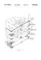
- FIG. 1shows a stylized fragmentary exploded view of a stripline array antenna incorporating a feed system constructed in accordance with the invention
- FIG. 2shows a cross-sectional view of the antenna taken along the line 2--2 in FIG. 1, FIG. 2 showing diagrammatically also external circuitry for energizing radiators of the antenna to accomplish a steering of a beam of the antenna in one plane;
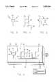
- FIG. 3shows diagrammatically a Wilkinson coupler
- FIG. 4shows diagrammatically a hybrid coupler
- FIG. 5shows diagrammatically a backward wave coupler
- FIG. 6shows diagrammatically a series of interconnected couplers.
- an array antenna 10is constructed in stripline form and includes a top electrically conductive layer 12, a middle layer 14 of electrically conductive elements, an upper dielectric layer 16 disposed between and contiguous to the top layer 12 and the middle layer 14, a bottom electrically conductive layer 18, and a lower dielectric layer 20 disposed between and contiguous to the middle layer 14 and the bottom layer 18.
- the top and the bottom layers 12 and 18serve as ground planes for electromagnetic signals propagating along conductors of the middle layer 14 and having electric fields extending through the dielectric layers 16 and 20 to the ground planes of the layers 12 and 18.
- Radiating elementsare constructed, by way of example, as parallel slots 22 disposed in rows and columns of a two-dimensional array extending in an XY plane of an XYZ orthogonal coordinate system 24.
- the rowsare parallel to the X axis, and the columns are parallel to the Y axis.
- Electromagnetic power radiated from the antenna 10propagates as a beam generally in the Z direction, as indicated by a radius vector R, and may be scanned, as indicated by scan in FIG. 1, in a plane perpendicular to the rows, namely, the XZ plane.
- the slots 22are positioned with a spacing Sx (shown in FIGS.
- the spacing Sy(shown in FIGS. 1 and 2) of the slots 22 along the perpendicular direction, namely, along the Y axis, is also one-half of the free-space wavelength.
- the electrically conductive layers 12, 14, and 18are formed of metal such as copper or aluminum, and the dielectric layers 16 and 20 are formed of a dielectric, electrically insulating material such as alumina.
- Conductors of the middle layer 14, to be described in further detail in FIG. 2,may be formed by photolithography.
- These conductorsinclude transmission line sections 26 which, as shown in FIG. 1, are arranged in alignment with the slots 22, and have their longitudinal dimensions oriented perpendicular to the direction of the slots 22. As will be described hereinafter with reference to FIGS. 2-6, the transmission line sections 26 constitute part of a feed system 28 and serve to couple electromagnetic signals to the slots 22, thereby to activate the slots 22 to emit radiation for formation of the aforementioned beam.
- Each of the transmission line sections 26extends beyond a central portion of its corresponding slot 22 by a distance equal to one quarter of a wavelength of an electromagnetic signal propagating within the stripline for matching impedance of each transmission line section 26 to the impedance of its slot 22.
- FIG. 2provides a sectional view of the antenna 10 taken along a surface of the middle conductor layer 14 so as to show details in the arrangement and the configurations of the conductive elements including stripline couplers which serve as power dividers for distribution of power among the slots 22.
- the circuitry 30comprises a source 32 of microwave power, such as a microwave oscillator (not shown) which is driven by a signal generator 34.
- the generator 34may include a modulator (not shown) for applying a phase and/or an amplitude modulation to a carrier signal outputted by the source 32.
- Power outputted by the source 32is divided by a divider 36 among a plurality of parallel channels 38 of which four channels 38A, 38B, 38C, 38D are shown by way of example.
- a variable phase shifter 40 and an amplifier 42through which a respective output signal of the power divider 36 is applied to the corresponding channel 38.
- each channel 38also comprises an assembly of interconnected stripline couplers including Wilkinson couplers 44, hybrid couplers 46, and backward wave couplers 48.
- input poweris coupled from the amplifier 42 to a central hybrid coupler 46A for distribution to both the left and the right sides of the stripline portion of the channel 38.
- the stripline portion of each channel 38is enclosed by a dashed line designating the middle conductor layer 14 of the antenna 10.
- the phase and the amplitude of each of the signals applied to the respective ones of the channels 38is controlled by the corresponding phase shifter 40 and amplifier 42 under command of a beam controller 50 of the circuitry 30.
- a differential phase shift provided to the respective channels 38, under command of the beam controller 50provides for a scanning of the beam, and the independent amplitude control for the respective channels 38 allows for a shaping of the beam profile.
- each amplifierFor reception of signals by the middle conductor layer 14, each amplifier would be part of a transmit-receive circuit (not shown) including a preamplifier for amplification of received signals.
- the received signals of the respective channels 38would be coupled via the phase shifters 40 and summed by the divider 36.
- the divider 36 and the phase shifters 40are operative in reciprocal fashion so as to allow the stripline circuitry of the middle layer 14 to operate in either the transmit or the receive mode.
- the stripline structure of the antenna 10(FIG. 1) can be converted to a microstrip structure by deletion of the bottom ground layer 18 and the lower dielectric layer 20.
- FIGS. 3-6show details in the construction and interconnection of the microwave couplers in both the stripline and the microstrip embodiments of the invention.
- the Wilkinson coupler 44is a three-terminal device having one input terminal, T1 and two output terminals T2 and T3. The two output terminals are connected by a load resistor 52.
- the hybrid coupler 46is a four terminal device having two input terminals T1 and T4, and two output terminals T2 and T3. One input terminal T1 receives the input signal, and the other input terminal is grounded by a load resistor 54.
- the backward wave coupler 48is a four terminal device having two input terminals T1 and T3, and two output terminals T2 and T4. One input terminal T1 receives the input signal, and the other input terminal is grounded by a load resistor 56.
- FIG. 6shows an example of an interconnection among the three forms of couplers.
- FIG. 6shows only the top layer 12, the middle layer 14, and the upper dielectric layer 16, to simplify the drawing.
- FIG. 6may be regarded as a microstrip embodiment of the invention.
- the two output terminals of the Wilkinson coupler 44are connected each to some form of power utilization device such as an antenna radiator 58.
- one output terminal of the hybrid coupler 46 and the backward wave coupler 48are connected each to a radiator 58.
- the connections of the couplers 44, 46, and 48 with their respective load resistors 52, 54, and 56, respectively,are as shown above with reference to FIGS. 3, 4, and 5.
- all three couplers 44, 46 and 48are interconnected by a single main conductor 60 extending in the row or Y direction, and adding no more than a negligible amount to the width W of the row. This maintains the narrow width of the assembly of couplers so as to permit the placement of the rows of the respective channels 38 within the required limitation of as small as one half of a free-space wavelength.
- Input electromagnetic poweris connected to the right end of the main conductor 60 by application of the microwave signal between the main conductor 60 and the ground of the top layer 12, as well as the ground of the bottom layer 18 (not shown in FIG. 6).
- the electromagnetic powerpropagates toward the left with a portion of the power being drawn off by the backward wave coupler 48 for its radiator 58, a portion being drawn off by the hybrid coupler 46 for its radiator 58, and the remainder being received by the Wilkinson coupler 44 for both its radiators 58.
- the backward wave coupler 48might extract minus 20 dB of the inputs power for its radiator 58
- the hybrid coupler 46might extract 10 dB of the remainder for its radiator 58
- the balancemight be divided evenly among the two radiators 58 of the Wilkinson coupler 44.
- the feature of the main conductor 60is attained by connecting only one output terminal of a coupler to a radiator 58, and by connecting the other output terminal to the next coupler, except for the last coupler in the series of couplers wherein both output terminals are connected to radiators 58.
- the coupler assemblyhas a width W equal essentially to the height of any one of the couplers 44, 46 and 48.
- each of the couplershas a minimum phase lag of 90 degrees between an input terminal and an output terminal.
- a signal propagating along the main conductor 60experiences a phase lag of 90 degrees in the passage through the backward wave coupler 48, another lag of 90 degrees during passage through the hybrid coupler 46, and a further lag of 90 degrees during passage through the Wilkinson coupler 44.
- the signalexperiences phase shift during propagation along the main conductor 60 between the couplers.
- the parameters of dielectric constant and thickness, as well as the widths of the conductors of the middle layer 14are selected to provide an accumulated phase shift of 360 degrees from the input terminal of one coupler to the input terminal of the next coupler.
- the signalexperiences a phase lag of 270 degrees between couplers.
- the backward wave coupler 48introduces a further 90 degrees phase shift between its output terminal on the main conductor 60 and its output terminal connected to the radiator 58.
- the hybrid coupler 48introduces a further 90 degrees phase shift between its output terminal on the main conductor 60 and its output terminal connected to the radiator 58.
- Further phase adjustmentcan be attained by placing bends (not shown in FIG. 6) in the main conductor 60. Thereby, the invention allows for adjustment of both phase and amplitude of signals applied to the radiators 58 of FIG. 6.
- each channel 38there are three main conductors 60A, 60B and 60C, each being generally parallel to the X axis (FIG. 1).
- the main conductor 60Aconnects the amplifier 42 to the center of the coupler assembly, at the central hybrid coupler 46A.
- the main conductor 60Bextends from the hybrid coupler 46A to the right side of the coupler assembly, and the main conductor 60C extends from the central hybrid coupler 46A to the left side of the coupler assembly.
- This opposed direction of feedingreverses the phases of the signals induced in the corresponding slots 22 (shown in FIG. 2) so as to attain substantial uniformity of radiation from the various slots 22.
- Additional phase shift adjustmentcan be obtained by addition of further length of stripline conductor between output terminal of a coupler and its associated transmission line section 62.
- the desired amplitudecan be obtained by configuring each coupler to provide the desired coupling ratio.
- the inventionprovides for a feed system wherein, in each channel 38, a desired phase and amplitude can be obtained by planar circuitry disposed parallel to a radiating aperture of the antenna 10, and within the constraints of one-half of a free-space wavelength in both the X and the Y coordinate directions of the radiating aperture.
Landscapes
- Variable-Direction Aerials And Aerial Arrays (AREA)
Abstract
Description
Claims (12)
Priority Applications (8)
| Application Number | Priority Date | Filing Date | Title |
|---|---|---|---|
| US07/904,597US5349364A (en) | 1992-06-26 | 1992-06-26 | Electromagnetic power distribution system comprising distinct type couplers |
| JP50264694AJP3467038B2 (en) | 1992-06-26 | 1993-06-25 | Electromagnetic force distribution system |
| DE69330953TDE69330953T2 (en) | 1992-06-26 | 1993-06-25 | DISTRIBUTION SYSTEM FOR ELECTROMAGNETIC ENERGY |
| RU94046292ARU2107974C1 (en) | 1992-06-26 | 1993-06-25 | Electromagnetic signal feeder system and antenna |
| AU47692/93AAU4769293A (en) | 1992-06-26 | 1993-06-25 | Electromagnetic power distribution system |
| EP93918136AEP0647358B1 (en) | 1992-06-26 | 1993-06-25 | Electromagnetic power distribution system |
| PCT/US1993/006202WO1994000890A1 (en) | 1992-06-26 | 1993-06-25 | Electromagnetic power distribution system |
| FI946065AFI946065A7 (en) | 1992-06-26 | 1994-12-23 | Electromagnetic distribution system |
Applications Claiming Priority (1)
| Application Number | Priority Date | Filing Date | Title |
|---|---|---|---|
| US07/904,597US5349364A (en) | 1992-06-26 | 1992-06-26 | Electromagnetic power distribution system comprising distinct type couplers |
Publications (1)
| Publication Number | Publication Date |
|---|---|
| US5349364Atrue US5349364A (en) | 1994-09-20 |
Family
ID=25419406
Family Applications (1)
| Application Number | Title | Priority Date | Filing Date |
|---|---|---|---|
| US07/904,597Expired - LifetimeUS5349364A (en) | 1992-06-26 | 1992-06-26 | Electromagnetic power distribution system comprising distinct type couplers |
Country Status (8)
| Country | Link |
|---|---|
| US (1) | US5349364A (en) |
| EP (1) | EP0647358B1 (en) |
| JP (1) | JP3467038B2 (en) |
| AU (1) | AU4769293A (en) |
| DE (1) | DE69330953T2 (en) |
| FI (1) | FI946065A7 (en) |
| RU (1) | RU2107974C1 (en) |
| WO (1) | WO1994000890A1 (en) |
Cited By (31)
| Publication number | Priority date | Publication date | Assignee | Title |
|---|---|---|---|---|
| US5428362A (en)* | 1994-02-07 | 1995-06-27 | Motorola, Inc. | Substrate integrated antenna |
| US5872547A (en)* | 1996-07-16 | 1999-02-16 | Metawave Communications Corporation | Conical omni-directional coverage multibeam antenna with parasitic elements |
| US6087988A (en)* | 1995-11-21 | 2000-07-11 | Raytheon Company | In-line CP patch radiator |
| WO2000051202A1 (en)* | 1999-02-26 | 2000-08-31 | Motorola Inc. | Beam steering planar array antenna |
| US6172654B1 (en) | 1996-07-16 | 2001-01-09 | Metawave Communications Corporation | Conical omni-directional coverage multibeam antenna |
| US6218978B1 (en)* | 1994-06-22 | 2001-04-17 | British Aerospace Public Limited Co. | Frequency selective surface |
| US6335662B1 (en)* | 1999-09-21 | 2002-01-01 | The United States Of America As Represented By The Secretary Of The Army | Ferroelectric-tunable microwave branching couplers |
| US20020061768A1 (en)* | 2000-09-21 | 2002-05-23 | National University Of Singapore | Beam synthesis method for downlink beamforming in FDD wireless communication system |
| US20030052750A1 (en)* | 2001-09-20 | 2003-03-20 | Khosro Shamsaifar | Tunable filters having variable bandwidth and variable delay |
| US6538603B1 (en)* | 2000-07-21 | 2003-03-25 | Paratek Microwave, Inc. | Phased array antennas incorporating voltage-tunable phase shifters |
| US20040130491A1 (en)* | 2001-04-26 | 2004-07-08 | David Hayes | Apparatus for providing a controllable signal delay along a transmission line |
| US20040145427A1 (en)* | 2003-01-27 | 2004-07-29 | Andrew Corporation | Quadrature hybrid low loss directional coupler |
| US20040207206A1 (en)* | 2001-04-20 | 2004-10-21 | Aloys Wobben | Method for operating a wind energy plant |
| US20050007212A1 (en)* | 2001-09-20 | 2005-01-13 | Khosro Shamsaifar | Tunable filters having variable bandwidth and variable delay |
| US20060001506A1 (en)* | 2004-06-30 | 2006-01-05 | Bahram Razmpoosh | Variable power coupling device |
| US7462947B2 (en) | 2001-04-20 | 2008-12-09 | Aloys Wobben | Method for operating a wind turbine |
| US20090190509A1 (en)* | 2008-01-29 | 2009-07-30 | Samsung Electronics Co. Ltd. | Apparatus and method for transmit/receive antenna switch in a tdd wireless communication system |
| US20100045348A1 (en)* | 2006-10-17 | 2010-02-25 | Mitsubishi Electric Corporation | Oscillator, transmitter-receiver and frequency synthesizer |
| US20100259449A1 (en)* | 2007-10-30 | 2010-10-14 | Rambus Inc. | Technique for determining an angle of arrival in a communication system |
| US20100309056A1 (en)* | 2009-06-09 | 2010-12-09 | Ahmadreza Rofougaran | Method and system for scanning rf channels utilizing leaky wave antennas |
| US20100321238A1 (en)* | 2009-06-18 | 2010-12-23 | Lin-Ping Shen | Butler matrix and beam forming antenna comprising same |
| US20140077874A1 (en)* | 2012-01-27 | 2014-03-20 | Freescale Semiconductor, Inc. | Adjustable power splitters and corresponding methods & apparatus |
| US9166301B2 (en) | 2012-02-13 | 2015-10-20 | AMI Research & Development, LLC | Travelling wave antenna feed structures |
| US9219453B2 (en) | 2012-01-27 | 2015-12-22 | Freescale Semiconductor, Inc. | Phase shift and attenuation circuits for use with multiple-path amplifiers |
| US9225291B2 (en) | 2013-10-29 | 2015-12-29 | Freescale Semiconductor, Inc. | Adaptive adjustment of power splitter |
| US9647611B1 (en) | 2015-10-28 | 2017-05-09 | Nxp Usa, Inc. | Reconfigurable power splitters and amplifiers, and corresponding methods |
| US9705199B2 (en) | 2014-05-02 | 2017-07-11 | AMI Research & Development, LLC | Quasi TEM dielectric travelling wave scanning array |
| US9774299B2 (en) | 2014-09-29 | 2017-09-26 | Nxp Usa, Inc. | Modifiable signal adjustment devices for power amplifiers and corresponding methods and apparatus |
| US9912068B2 (en)* | 2014-02-04 | 2018-03-06 | Kabushiki Kaisha Toshiba | Antenna apparatus and radar apparatus |
| US11038263B2 (en)* | 2015-11-12 | 2021-06-15 | Duke University | Printed cavities for computational microwave imaging and methods of use |
| RU208172U1 (en)* | 2021-07-05 | 2021-12-07 | Федеральное государственное автономное образовательное учреждение высшего образования «Южно-Уральский государственный университет (национальный исследовательский университет)» ФГАОУ ВО «ЮУрГУ (НИУ)» | Duplexer based on volumetric strip-slot junctions |
Families Citing this family (2)
| Publication number | Priority date | Publication date | Assignee | Title |
|---|---|---|---|---|
| NZ521823A (en)* | 2002-10-04 | 2005-11-25 | Ind Res Ltd | An array of antenna elements used as a microwave sensor to grade produce such as fruit |
| GB0307558D0 (en)* | 2003-04-02 | 2003-05-07 | Qinetiq Ltd | Phased array antenna system with variable electrical tilt |
Citations (29)
| Publication number | Priority date | Publication date | Assignee | Title |
|---|---|---|---|---|
| US2414431A (en)* | 1942-07-01 | 1947-01-21 | Standard Telephones Cables Ltd | Radio beacon |
| US2789271A (en)* | 1948-10-05 | 1957-04-16 | Bell Telephone Labor Inc | Hybrid ring coupling arrangement |
| US3071769A (en)* | 1958-01-16 | 1963-01-01 | North American Aviation Inc | Four horn feed bridge |
| US3295134A (en)* | 1965-11-12 | 1966-12-27 | Sanders Associates Inc | Antenna system for radiating directional patterns |
| US3307189A (en)* | 1961-03-22 | 1967-02-28 | John E Meade | Microwave antenna lobing |
| US3375524A (en)* | 1963-10-10 | 1968-03-26 | Siemens Ag | Antenna distributor circuit for four dipoles with adjacent dipoles in phase quadrature |
| US3495263A (en)* | 1967-12-06 | 1970-02-10 | Us Army | Phased array antenna system |
| US3668567A (en)* | 1970-07-02 | 1972-06-06 | Hughes Aircraft Co | Dual mode rotary microwave coupler |
| US3701158A (en)* | 1970-01-22 | 1972-10-24 | Motorola Inc | Dual mode wave energy transducer device |
| US4101892A (en)* | 1975-11-19 | 1978-07-18 | Andrew Alford | Localizer antenna array for use with localizer transmitters operating at one carrier frequency |
| US4231040A (en)* | 1978-12-11 | 1980-10-28 | Motorola, Inc. | Simultaneous multiple beam antenna array matrix and method thereof |
| US4241352A (en)* | 1976-09-15 | 1980-12-23 | Ball Brothers Research Corporation | Feed network scanning antenna employing rotating directional coupler |
| US4316159A (en)* | 1979-01-22 | 1982-02-16 | Rca Corporation | Redundant microwave switching matrix |
| US4423392A (en)* | 1981-11-30 | 1983-12-27 | Wolfson Ronald I | Dual-mode stripline antenna feed performing multiple angularly separated beams in space |
| US4427936A (en)* | 1981-06-22 | 1984-01-24 | Microwave Development Labs | Reflection coefficient measurements |
| US4471361A (en)* | 1982-09-23 | 1984-09-11 | Rca Corporation | Phase reconfigurable beam antenna system |
| DE3503445A1 (en)* | 1984-03-27 | 1985-10-03 | Laboratoire Central de Télécommunications, Velizy-Villacoublay | Method for compensation of the phase shift in the case of power distributors, and a distributor for carrying out the method |
| US4584582A (en)* | 1981-08-31 | 1986-04-22 | Motorola, Inc. | Multi-mode direction finding antenna |
| US4639694A (en)* | 1984-04-27 | 1987-01-27 | Mitsubishi Denki Kabushiki Kaisha | Power distribution circuit having center portions of isolation resistors connected together |
| US4652880A (en)* | 1984-06-04 | 1987-03-24 | Allied Corporation | Antenna feed network |
| US4689627A (en)* | 1983-05-20 | 1987-08-25 | Hughes Aircraft Company | Dual band phased antenna array using wideband element with diplexer |
| US4691177A (en)* | 1985-10-02 | 1987-09-01 | Hughes Aircraft Company | Waveguide switch with variable short wall coupling |
| US4710776A (en)* | 1984-01-05 | 1987-12-01 | Agence Spatiale Europeenne | Power divider for multibeam antennas with shared feed elements |
| US4764771A (en)* | 1986-08-04 | 1988-08-16 | Itt Gilfillan, A Division Of Itt Corporation | Antenna feed network employing over-coupled branch line couplers |
| US4827270A (en)* | 1986-12-22 | 1989-05-02 | Mitsubishi Denki Kabushiki Kaisha | Antenna device |
| US4965588A (en)* | 1988-03-18 | 1990-10-23 | Societe Anonyme Dite : Alcatel Espace | Electronically scanned antenna |
| USH880H (en)* | 1987-08-10 | 1991-01-01 | The United States Of America As Represented By The Secretary Of The Air Force | In-plane transmission line crossover |
| US5001492A (en)* | 1988-10-11 | 1991-03-19 | Hughes Aircraft Company | Plural layer co-planar waveguide coupling system for feeding a patch radiator array |
| US5189433A (en)* | 1991-10-09 | 1993-02-23 | The United States Of America As Represented By The Secretary Of The Army | Slotted microstrip electronic scan antenna |
Family Cites Families (2)
| Publication number | Priority date | Publication date | Assignee | Title |
|---|---|---|---|---|
| FR85806E (en) | 1963-05-07 | 1965-10-22 | Csf | Broadband aerial direction finding |
| JPH01157603A (en)* | 1987-12-15 | 1989-06-20 | Matsushita Electric Works Ltd | Plane antenna |
- 1992
- 1992-06-26USUS07/904,597patent/US5349364A/ennot_activeExpired - Lifetime
- 1993
- 1993-06-25DEDE69330953Tpatent/DE69330953T2/ennot_activeExpired - Fee Related
- 1993-06-25JPJP50264694Apatent/JP3467038B2/ennot_activeExpired - Fee Related
- 1993-06-25EPEP93918136Apatent/EP0647358B1/ennot_activeExpired - Lifetime
- 1993-06-25WOPCT/US1993/006202patent/WO1994000890A1/enactiveIP Right Grant
- 1993-06-25AUAU47692/93Apatent/AU4769293A/ennot_activeAbandoned
- 1993-06-25RURU94046292Apatent/RU2107974C1/ennot_activeIP Right Cessation
- 1994
- 1994-12-23FIFI946065Apatent/FI946065A7/enunknown
Patent Citations (29)
| Publication number | Priority date | Publication date | Assignee | Title |
|---|---|---|---|---|
| US2414431A (en)* | 1942-07-01 | 1947-01-21 | Standard Telephones Cables Ltd | Radio beacon |
| US2789271A (en)* | 1948-10-05 | 1957-04-16 | Bell Telephone Labor Inc | Hybrid ring coupling arrangement |
| US3071769A (en)* | 1958-01-16 | 1963-01-01 | North American Aviation Inc | Four horn feed bridge |
| US3307189A (en)* | 1961-03-22 | 1967-02-28 | John E Meade | Microwave antenna lobing |
| US3375524A (en)* | 1963-10-10 | 1968-03-26 | Siemens Ag | Antenna distributor circuit for four dipoles with adjacent dipoles in phase quadrature |
| US3295134A (en)* | 1965-11-12 | 1966-12-27 | Sanders Associates Inc | Antenna system for radiating directional patterns |
| US3495263A (en)* | 1967-12-06 | 1970-02-10 | Us Army | Phased array antenna system |
| US3701158A (en)* | 1970-01-22 | 1972-10-24 | Motorola Inc | Dual mode wave energy transducer device |
| US3668567A (en)* | 1970-07-02 | 1972-06-06 | Hughes Aircraft Co | Dual mode rotary microwave coupler |
| US4101892A (en)* | 1975-11-19 | 1978-07-18 | Andrew Alford | Localizer antenna array for use with localizer transmitters operating at one carrier frequency |
| US4241352A (en)* | 1976-09-15 | 1980-12-23 | Ball Brothers Research Corporation | Feed network scanning antenna employing rotating directional coupler |
| US4231040A (en)* | 1978-12-11 | 1980-10-28 | Motorola, Inc. | Simultaneous multiple beam antenna array matrix and method thereof |
| US4316159A (en)* | 1979-01-22 | 1982-02-16 | Rca Corporation | Redundant microwave switching matrix |
| US4427936A (en)* | 1981-06-22 | 1984-01-24 | Microwave Development Labs | Reflection coefficient measurements |
| US4584582A (en)* | 1981-08-31 | 1986-04-22 | Motorola, Inc. | Multi-mode direction finding antenna |
| US4423392A (en)* | 1981-11-30 | 1983-12-27 | Wolfson Ronald I | Dual-mode stripline antenna feed performing multiple angularly separated beams in space |
| US4471361A (en)* | 1982-09-23 | 1984-09-11 | Rca Corporation | Phase reconfigurable beam antenna system |
| US4689627A (en)* | 1983-05-20 | 1987-08-25 | Hughes Aircraft Company | Dual band phased antenna array using wideband element with diplexer |
| US4710776A (en)* | 1984-01-05 | 1987-12-01 | Agence Spatiale Europeenne | Power divider for multibeam antennas with shared feed elements |
| DE3503445A1 (en)* | 1984-03-27 | 1985-10-03 | Laboratoire Central de Télécommunications, Velizy-Villacoublay | Method for compensation of the phase shift in the case of power distributors, and a distributor for carrying out the method |
| US4639694A (en)* | 1984-04-27 | 1987-01-27 | Mitsubishi Denki Kabushiki Kaisha | Power distribution circuit having center portions of isolation resistors connected together |
| US4652880A (en)* | 1984-06-04 | 1987-03-24 | Allied Corporation | Antenna feed network |
| US4691177A (en)* | 1985-10-02 | 1987-09-01 | Hughes Aircraft Company | Waveguide switch with variable short wall coupling |
| US4764771A (en)* | 1986-08-04 | 1988-08-16 | Itt Gilfillan, A Division Of Itt Corporation | Antenna feed network employing over-coupled branch line couplers |
| US4827270A (en)* | 1986-12-22 | 1989-05-02 | Mitsubishi Denki Kabushiki Kaisha | Antenna device |
| USH880H (en)* | 1987-08-10 | 1991-01-01 | The United States Of America As Represented By The Secretary Of The Air Force | In-plane transmission line crossover |
| US4965588A (en)* | 1988-03-18 | 1990-10-23 | Societe Anonyme Dite : Alcatel Espace | Electronically scanned antenna |
| US5001492A (en)* | 1988-10-11 | 1991-03-19 | Hughes Aircraft Company | Plural layer co-planar waveguide coupling system for feeding a patch radiator array |
| US5189433A (en)* | 1991-10-09 | 1993-02-23 | The United States Of America As Represented By The Secretary Of The Army | Slotted microstrip electronic scan antenna |
Cited By (53)
| Publication number | Priority date | Publication date | Assignee | Title |
|---|---|---|---|---|
| US5428362A (en)* | 1994-02-07 | 1995-06-27 | Motorola, Inc. | Substrate integrated antenna |
| US6218978B1 (en)* | 1994-06-22 | 2001-04-17 | British Aerospace Public Limited Co. | Frequency selective surface |
| US6087988A (en)* | 1995-11-21 | 2000-07-11 | Raytheon Company | In-line CP patch radiator |
| US5872547A (en)* | 1996-07-16 | 1999-02-16 | Metawave Communications Corporation | Conical omni-directional coverage multibeam antenna with parasitic elements |
| US6172654B1 (en) | 1996-07-16 | 2001-01-09 | Metawave Communications Corporation | Conical omni-directional coverage multibeam antenna |
| WO2000051202A1 (en)* | 1999-02-26 | 2000-08-31 | Motorola Inc. | Beam steering planar array antenna |
| US6184827B1 (en) | 1999-02-26 | 2001-02-06 | Motorola, Inc. | Low cost beam steering planar array antenna |
| US6335662B1 (en)* | 1999-09-21 | 2002-01-01 | The United States Of America As Represented By The Secretary Of The Army | Ferroelectric-tunable microwave branching couplers |
| US6538603B1 (en)* | 2000-07-21 | 2003-03-25 | Paratek Microwave, Inc. | Phased array antennas incorporating voltage-tunable phase shifters |
| US7359733B2 (en)* | 2000-09-21 | 2008-04-15 | Ying-Chang Liang | Beam synthesis method for downlink beamforming in FDD wireless communication system |
| US20020061768A1 (en)* | 2000-09-21 | 2002-05-23 | National University Of Singapore | Beam synthesis method for downlink beamforming in FDD wireless communication system |
| US20040207206A1 (en)* | 2001-04-20 | 2004-10-21 | Aloys Wobben | Method for operating a wind energy plant |
| US7462947B2 (en) | 2001-04-20 | 2008-12-09 | Aloys Wobben | Method for operating a wind turbine |
| US7462946B2 (en)* | 2001-04-20 | 2008-12-09 | Aloys Wobben | Method for operating a wind energy plant |
| US20040130491A1 (en)* | 2001-04-26 | 2004-07-08 | David Hayes | Apparatus for providing a controllable signal delay along a transmission line |
| US6879289B2 (en)* | 2001-04-26 | 2005-04-12 | Plasma Antennas, Ltd. | Apparatus for providing a controllable signal delay along a transmission line |
| US20030052750A1 (en)* | 2001-09-20 | 2003-03-20 | Khosro Shamsaifar | Tunable filters having variable bandwidth and variable delay |
| US6801102B2 (en) | 2001-09-20 | 2004-10-05 | Paratek Microwave Incorporated | Tunable filters having variable bandwidth and variable delay |
| US20050007212A1 (en)* | 2001-09-20 | 2005-01-13 | Khosro Shamsaifar | Tunable filters having variable bandwidth and variable delay |
| US7034636B2 (en) | 2001-09-20 | 2006-04-25 | Paratek Microwave Incorporated | Tunable filters having variable bandwidth and variable delay |
| US20040145427A1 (en)* | 2003-01-27 | 2004-07-29 | Andrew Corporation | Quadrature hybrid low loss directional coupler |
| US6956449B2 (en) | 2003-01-27 | 2005-10-18 | Andrew Corporation | Quadrature hybrid low loss directional coupler |
| US7342467B2 (en) | 2004-06-30 | 2008-03-11 | Harris Stratex Networks, Inc. | Variable power coupling device |
| US20070268090A1 (en)* | 2004-06-30 | 2007-11-22 | Harris Stratex Networks, Inc. | Variable Power Coupling Device |
| US7443266B2 (en) | 2004-06-30 | 2008-10-28 | Harris Stratex Networks, Inc. | Variable power coupling device |
| US20060001506A1 (en)* | 2004-06-30 | 2006-01-05 | Bahram Razmpoosh | Variable power coupling device |
| US20100045348A1 (en)* | 2006-10-17 | 2010-02-25 | Mitsubishi Electric Corporation | Oscillator, transmitter-receiver and frequency synthesizer |
| US8018290B2 (en)* | 2006-10-17 | 2011-09-13 | Mitsubishi Electric Corporation | Oscillator, transmitter-receiver and frequency synthesizer |
| US20100259449A1 (en)* | 2007-10-30 | 2010-10-14 | Rambus Inc. | Technique for determining an angle of arrival in a communication system |
| US8207892B2 (en)* | 2007-10-30 | 2012-06-26 | Rambus Inc. | Technique for determining an angle of arrival in a communication system |
| US20090190509A1 (en)* | 2008-01-29 | 2009-07-30 | Samsung Electronics Co. Ltd. | Apparatus and method for transmit/receive antenna switch in a tdd wireless communication system |
| US7844231B2 (en)* | 2008-01-29 | 2010-11-30 | Samsung Electronics Co., Ltd. | Apparatus and method for transmit/receive antenna switch in a TDD wireless communication system |
| US20100309056A1 (en)* | 2009-06-09 | 2010-12-09 | Ahmadreza Rofougaran | Method and system for scanning rf channels utilizing leaky wave antennas |
| US20100309052A1 (en)* | 2009-06-09 | 2010-12-09 | Ahmadreza Rofougaran | Method and system for dynamic tracking utilizing leaky wave antennas |
| US8242957B2 (en)* | 2009-06-09 | 2012-08-14 | Broadcom Corporation | Method and system for dynamic tracking utilizing leaky wave antennas |
| US20100321238A1 (en)* | 2009-06-18 | 2010-12-23 | Lin-Ping Shen | Butler matrix and beam forming antenna comprising same |
| US9219453B2 (en) | 2012-01-27 | 2015-12-22 | Freescale Semiconductor, Inc. | Phase shift and attenuation circuits for use with multiple-path amplifiers |
| US9876475B2 (en) | 2012-01-27 | 2018-01-23 | Nxp Usa, Inc. | Phase shift and attenuation circuits for use with multiple-path amplifiers |
| US9203348B2 (en)* | 2012-01-27 | 2015-12-01 | Freescale Semiconductor, Inc. | Adjustable power splitters and corresponding methods and apparatus |
| US20140077874A1 (en)* | 2012-01-27 | 2014-03-20 | Freescale Semiconductor, Inc. | Adjustable power splitters and corresponding methods & apparatus |
| US9374051B2 (en) | 2012-01-27 | 2016-06-21 | Freescale Semiconductor, Inc. | Phase shift and attenuation circuits for use with multiple-path amplifiers |
| US9490755B2 (en) | 2012-01-27 | 2016-11-08 | Freescale Semiconductor, Inc. | Phase shift and attenuation circuits for use with multiple-path amplifiers |
| US9509056B2 (en) | 2012-02-13 | 2016-11-29 | AMI Research & Development, LLC | Travelling wave antenna feed structures |
| US9166301B2 (en) | 2012-02-13 | 2015-10-20 | AMI Research & Development, LLC | Travelling wave antenna feed structures |
| US9225291B2 (en) | 2013-10-29 | 2015-12-29 | Freescale Semiconductor, Inc. | Adaptive adjustment of power splitter |
| US9912068B2 (en)* | 2014-02-04 | 2018-03-06 | Kabushiki Kaisha Toshiba | Antenna apparatus and radar apparatus |
| US9705199B2 (en) | 2014-05-02 | 2017-07-11 | AMI Research & Development, LLC | Quasi TEM dielectric travelling wave scanning array |
| US9774299B2 (en) | 2014-09-29 | 2017-09-26 | Nxp Usa, Inc. | Modifiable signal adjustment devices for power amplifiers and corresponding methods and apparatus |
| US10027284B2 (en) | 2014-09-29 | 2018-07-17 | Nxp Usa, Inc. | Modifiable signal adjustment devices for power amplifiers and corresponding methods and apparatus |
| US9647611B1 (en) | 2015-10-28 | 2017-05-09 | Nxp Usa, Inc. | Reconfigurable power splitters and amplifiers, and corresponding methods |
| US11038263B2 (en)* | 2015-11-12 | 2021-06-15 | Duke University | Printed cavities for computational microwave imaging and methods of use |
| US20210288397A1 (en)* | 2015-11-12 | 2021-09-16 | Duke University | Printed cavities for computational microwave imaging and methods of use |
| RU208172U1 (en)* | 2021-07-05 | 2021-12-07 | Федеральное государственное автономное образовательное учреждение высшего образования «Южно-Уральский государственный университет (национальный исследовательский университет)» ФГАОУ ВО «ЮУрГУ (НИУ)» | Duplexer based on volumetric strip-slot junctions |
Also Published As
| Publication number | Publication date |
|---|---|
| FI946065A0 (en) | 1994-12-23 |
| EP0647358A4 (en) | 1995-08-02 |
| DE69330953T2 (en) | 2002-07-18 |
| JPH08501419A (en) | 1996-02-13 |
| EP0647358A1 (en) | 1995-04-12 |
| JP3467038B2 (en) | 2003-11-17 |
| AU4769293A (en) | 1994-01-24 |
| RU2107974C1 (en) | 1998-03-27 |
| EP0647358B1 (en) | 2001-10-17 |
| FI946065A7 (en) | 1994-12-23 |
| WO1994000890A1 (en) | 1994-01-06 |
| DE69330953D1 (en) | 2001-11-22 |
Similar Documents
| Publication | Publication Date | Title |
|---|---|---|
| US5349364A (en) | Electromagnetic power distribution system comprising distinct type couplers | |
| US4652880A (en) | Antenna feed network | |
| JP4597985B2 (en) | Method and apparatus for forming millimeter wave phased array antenna | |
| EP0456680B1 (en) | Antenna arrays | |
| JP2585413B2 (en) | Low sidelobe phased array antenna using the same solid state module. | |
| US4812788A (en) | Waveguide matrix including in-plane crossover | |
| EP0600715B1 (en) | Active transmit phased array antenna | |
| US6759980B2 (en) | Phased array antennas incorporating voltage-tunable phase shifters | |
| JP2000244224A (en) | Multi-beam antenna and antenna system | |
| WO1999036992A9 (en) | Array antenna having multiple independently steered beams | |
| EP0313058B1 (en) | Coaxial transmission-line matrix including in-plane crossover | |
| US5955998A (en) | Electronically scanned ferrite line source | |
| US4605931A (en) | Crossover traveling wave feed for microstrip antenna array | |
| GB1600346A (en) | Antenna system having modular coupling network | |
| US3525995A (en) | Amplitude tapering,nonsymmetrical binary feed networks for highpower hf phased arrays | |
| JP3345767B2 (en) | Multi-beam antenna feed circuit | |
| TW202320414A (en) | Phased array antenna device | |
| CN115693180A (en) | Phased Array Antenna Equipment | |
| US4476470A (en) | Three horn E-plane monopulse feed | |
| WO1999012229A1 (en) | Electronically scanned ferrite line source |
Legal Events
| Date | Code | Title | Description |
|---|---|---|---|
| AS | Assignment | Owner name:AVCO CORPORATION, RHODE ISLAND Free format text:ASSIGNMENT OF ASSIGNORS INTEREST.;ASSIGNORS:BRYANOS, JAMES;SOULE, TIMOTHY;HARRIS, MICHAEL;REEL/FRAME:006223/0479 Effective date:19920810 | |
| STCF | Information on status: patent grant | Free format text:PATENTED CASE | |
| CC | Certificate of correction | ||
| AS | Assignment | Owner name:TEXTRON SYSTEMS CORPORATION, DELAWARE Free format text:ASSIGNMENT OF ASSIGNORS INTEREST;ASSIGNOR:AVCO CORPORATION;REEL/FRAME:008392/0930 Effective date:19970311 | |
| FEPP | Fee payment procedure | Free format text:PAYOR NUMBER ASSIGNED (ORIGINAL EVENT CODE: ASPN); ENTITY STATUS OF PATENT OWNER: LARGE ENTITY | |
| FPAY | Fee payment | Year of fee payment:4 | |
| FPAY | Fee payment | Year of fee payment:8 | |
| AS | Assignment | Owner name:TEXTRON IPMP L.P., MICHIGAN Free format text:ASSIGNMENT OF ASSIGNORS INTEREST;ASSIGNORS:AVCO CORPORATION;TEXTRON SYSTEMS;AVCO MICHIGAN;REEL/FRAME:015156/0816 Effective date:20010401 | |
| FPAY | Fee payment | Year of fee payment:12 |