US5349329A - Vehicle security apparatus and method - Google Patents
Vehicle security apparatus and methodDownload PDFInfo
- Publication number
- US5349329A US5349329AUS08/059,448US5944893AUS5349329AUS 5349329 AUS5349329 AUS 5349329AUS 5944893 AUS5944893 AUS 5944893AUS 5349329 AUS5349329 AUS 5349329A
- Authority
- US
- United States
- Prior art keywords
- vehicle
- signal
- operative
- switch
- control circuit
- Prior art date
- Legal status (The legal status is an assumption and is not a legal conclusion. Google has not performed a legal analysis and makes no representation as to the accuracy of the status listed.)
- Expired - Fee Related
Links
Images


Classifications
- B—PERFORMING OPERATIONS; TRANSPORTING
- B60—VEHICLES IN GENERAL
- B60R—VEHICLES, VEHICLE FITTINGS, OR VEHICLE PARTS, NOT OTHERWISE PROVIDED FOR
- B60R25/00—Fittings or systems for preventing or indicating unauthorised use or theft of vehicles
- B60R25/01—Fittings or systems for preventing or indicating unauthorised use or theft of vehicles operating on vehicle systems or fittings, e.g. on doors, seats or windscreens
- B60R25/04—Fittings or systems for preventing or indicating unauthorised use or theft of vehicles operating on vehicle systems or fittings, e.g. on doors, seats or windscreens operating on the propulsion system, e.g. engine or drive motor
Definitions
- the present inventionbroadly concerns protective devices and methods used to provide security for vehicles against theft. More specifically, the present invention relates to apparatus and methods that may be employed to protect against theft while the vehicle is in operation by causing removal of the operator therefrom under force or threat of force.
- the present inventionaddresses the need for security systems to prevent or deter car jacking and employs a new and non-obvious integration of electronic proximity detection with electronic control circuitry of a vehicle.
- vehiclecould broadly encompass any motor powered transportation vehicle including, but not limited to, cars, trucks, boats, etc.
- motor poweredin this context is not limited to vehicles powered by internal combustion engines but could include the developing technology of electric vehicles or other power systems as well.
- the present inventionis directed to interact with the electronic control system of such motor powered vehicles whether it be the electronic ignition system of a typical internal combustion engine driven vehicle or any of the electronic circuitry of an electrically powered vehicle.
- proximity detectionmay utilize a transmitter which transmits a signal, such as a radio signal, on a selected frequency, and a receiver tuned to receive that frequency.
- a signalsuch as a radio signal
- a receivertuned to receive that frequency.
- an alarmis sounded when the transmitter and receiver come within a threshold distance of one another, and the receiver thereby receives the transmitted signal, in order to sound an alarm indicating such closeness.
- Another implementation of such technologycontemplates the indication of an alarm when the transmitter and receiver are separated a distance greater than a threshold communication distance.
- the receivercorrespondingly, is tuned to the selected frequency and is adjustable in sensitivity to set the predetermined range of operation.
- a timer circuitis provided which reset each time a pulse is detected by the receiver but, after the absence of a series of pulses, the timer triggers and activates an alarm.
- U.S. Pat. No. 4,785,291 issued Nov. 15, 1988 to Hawthornediscloses a monitoring apparatus that is affixed to a person, such as a child, to be monitored and a receiver/monitor apparatus that may be maintained, for example, by a parent to monitor the movement of the child beyond a predetermined range.
- U.S. Pat. No. 4,675,656 issued Jun. 23, 1987 to Narcisselikewise shows an out-of-range personal monitor and alarm.
- Another object of the present inventionis to provide an apparatus and method for combating forced usurpation, i.e. "car jacking", of a vehicle from the rightful operator.
- a further object of the present inventionis to provide an apparatus and method for temporarily disabling a vehicle should it be improperly removed from the vicinity of the rightful operator.
- a still further object of the present inventionis to provide an apparatus that may retro-fit onto the existing electronic controlled systems of motor powered vehicles in order to monitor the presence of the rightful operator and to benignly disable operation of the vehicle should the operator be displaced and the vehicle stolen while the vehicle is in operation.
- Yet another object of the present inventionis to provide an inexpensive, reliable security system and method of protecting a vehicle which is simple to install on existing vehicles without interfering with the normal operation thereof yet which will protect against car jacking.
- an anti-theft apparatus and methodfor use with motor powered vehicles.
- the anti-theft apparatusis adapted to interconnect with an electronic control circuit of the vehicle and is operative to selectively disrupt the control circuit to disable the vehicle.
- the apparatusincludes a transmitter which is adapted to be carried by a driver of the vehicle and which is operative to produce a broadcast signal of selected frequency.
- the vehiclecarries a receiver, and this receiver is operative to receive the broadcast signal when the transmitter is within a communication range. When the receiver fails to receive the broadcast signal, when the transmitter is out of the communication range, the receiver operates to produce an out-of-range signal.
- a switch circuitincludes a switch element that is interposed in the electronic control circuit of the vehicle and has a switch active state wherein said control circuit is operative so that the vehicle is enabled and a switch inactive state wherein the control circuit is disrupted to disable the vehicle.
- a switch control circuitis provided and operates in response to the out-of-range signal to cause the switch element to change from the switch active state to the switch inactive state.
- the anti-theft apparatusincludes timer circuitry associated with the receiver so that the out-of-range signal is produced only after the receiver fails to receive the broadcast signal for a selected time duration, for example, approximately five seconds.
- the anti-theft apparatusincludes an event detector operative to sense the occurrence of a selected event, such as the opening of a door of the vehicle, and produces an arming signal in response to the occurrence.
- the switch control circuitis then operative in response to the out-of-range signal to cause the switch element to change from the switch active state to the switch inactive state only when the arming signal is present.
- the event detectorincludes a time out circuit operative to discontinue the arming signal following a time interval after the occurrence of the event, and this time interval may be selected to be in the range of two to ten minutes.
- the event detectormay be electrically connected to a standard door monitoring circuit provided in the vehicle.
- the switch control circuitpreferably operates to lock the switch element in a switch inactive state in response to the out-of-range signal, and a reset circuit is provided in order to be selectively actuated to unlock the switch element from the switch inactive state.
- the broad method according to the present inventioncontemplates the method of protecting a motor vehicle from theft accomplished by usurping operation of the vehicle from an operator thereof, displacing the operator out of the vehicle and removing the vehicle away from the operator.
- the methodis that method which is implemented by the above-described apparatus, and the method includes a first step of providing first means carried by the operator of the vehicle and second means carried by the vehicle with said first and second means for detecting a distance of separation between the operator and the vehicle.
- a second stepincludes the interposition of a switch element in the electronic control circuit of the vehicle wherein the switch element has a switch active state whereby the control circuit is operative and a switch inactive state whereby the control circuit is disrupted.
- the methodincludes the step of monitoring the distance of separation between the operator and the vehicle and changing the switch element from the switch active state to the switch inactive state when a distance of separation exceeds a threshold distance.
- This broad methodmay include the step of changing the switch element from the switch active state to the switch inactive state only after the distance of separation has exceeded the threshold distance continuously for a selected time duration.
- the broad methodmay also include the step of monitoring for an occurrence of a selected event and wherein the step of changing the switch element from the switch active state to the switch inactive state occurs only if the distance of separation exceeds the threshold distance within a selected interval of time following occurrence of the selected event.
- This selected eventis preferred to be the opening of a door, and the method includes the step of interconnecting a detector element to the door monitoring circuit of the motor powered vehicle.
- FIG. 1is a block diagram showing a first exemplary embodiment of the present invention
- FIG. 2is a partial block diagram and partial schematic diagram of the electronic circuitry according to the invention shown in FIG. 1;
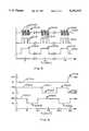
- FIG. 3is a graph showing the wave form of the unprocessed broadcast signal as well as the processed broadcast signal presented by the receiver to the signal loss timer;
- FIG. 4is a graph showing the representative timing and wave form of the arming, out-of-range and disable signals according to the embodiment of the invention shown in FIGS. 1 and 2;
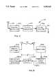
- FIG. 5is a block diagram showing a transmitter of a type for use with the present invention.
- FIG. 6is a schematic diagram of the preferred form of the transmitter of FIG. 5;
- FIG. 7is a block diagram showing a receiver of a type which may be used with the transmitter of FIG. 5;
- FIG. 8is a schematic diagram of the preferred form of the receiver shown in FIG. 7;
- FIG. 9is a block diagram of a more generalized exemplary embodiment of the present invention.
- the present inventionis directed to providing an anti-theft apparatus and method adapted for use with standard motor powered vehicles in order to prevent or deter theft of such vehicles.
- the apparatusis constructed so that it may be included as original equipment with a vehicle during manufacturer or which may be easily and cheaply retro-fitted onto an existing vehicle.
- the apparatus and methodconcerns the interrupting of an electronic control circuit of the vehicle in order to disable the vehicle in the event of theft, and particularly, car jacking.
- the electronic control circuit of the vehiclemay be the ignition circuit for an internal combustion engine driven vehicle or any electrical power circuit for an electric vehicle, and the like.
- anti-theft apparatus 10includes a transmitter 12 having an antenna 13 and a receiver 14 having an antenna 15.
- Receiver 14includes a receiver unit 16 connected to antenna 15 and a signal loss timer 18 operative to receive signals from receiver unit 16.
- Transmitter 12operates to produce a broadcast signal of a selected frequency as represented by broadcast signal "S”.
- Receiver 14operates to receive the broadcast signal at input 17.
- receiver unit 16process analog signal "S" to produce a digital pulse signal that is counted by signal loss timer 18 so that, in the event that receiver 14 looses the broadcast signal for a selected time interval, signal loss timer 18 produces an "out-of-range" signal at output 20.
- Transmitter 12is adapted to be carried by a driver of the vehicle while receiver 14 is adapted to be mounted to or carried in the vehicle and is operative to receive the broadcast signal when transmitter 12 is within a communication range of the receiver 14.
- An event detectoris provided and is operative to sense the occurrence of a selected event and to produce an arming signal in response to that occurrence.
- the occurrence to be sensedis the opening of a selected door of the vehicle.
- anti-theft apparatus 10includes a detector circuit 30 having a door open detector sub-circuit 32 which produces an arming signal at output 34 when the event, such as the opening of the vehicle door, occurs.
- the arming signalis presented to a time out sub-circuit 36 which acts to present the arming signal to an inverter 38 which forms part of detector circuit 30.
- a switch control circuit 50includes a logic element 52 that is operative to receive both the out-of-range signal from output 20 and the inverted arming signal from output 40 from inverter 38.
- the arming signal from time out sub-circuit 36may be presented to an arm alarm 54 while the out-of-range signal may be presented to a signal loss alarm 56 as shown in this Figure.
- Alarms 54 and 56may be audio alarms, visual displays, indicator lights or the like.
- logic element 52acts to sense the presence of both the arming signal and the out-of-range signal to produce a control signal at output 58 thereof.
- Control signal 58is presented to input 62 of flip-flop element 60 which, upon receipt of the control signal at input 62 produces a disable signal at output 64 thereof.
- a disabled signalmay be presented to a disable alarm 66 which again may be an audio, visual or other indicator alarm.
- the disable signal from output 64 of flip-flop 60is presented to a disable sub-circuit 68 that is operative to drive a control circuit switch 80 that is interposed in the control circuit of the vehicle.
- Control circuit switch 80is normally biased into an active state wherein the electronic control circuit of the vehicle is enabled.
- disabled sub-circuit 68causes a control circuit switch to move into an inactive state which disrupts the electronic vehicle control circuit 80 of the vehicle thereby disabling operation of the vehicle.
- the block diagram circuit of FIG. 1may be simply implemented by the electronic circuitry shown in FIG. 2.
- door open detector 32is connected to the door monitoring circuit 100 of a standard vehicle.
- this door monitoring circuitincludes a door switch that normally in an open state but, when the door opens, the door switch activates, for example, to light the interior compartment of the vehicle by means of door or overhead lights.
- This circuitmay also include a "door ajar” alarm to advise the operator that the door is not completely closed.
- the door monitoring circuit of most vehiclesis powered at 12 volts and, when the door is opened, the switch connects the circuit to ground.
- the door open detector sub-circuit of the present inventionincludes a resistor 102 and a diode 104 connected in series between a positive voltage source V + , and a door monitoring circuit 100.
- the connecting point 106 between resistor 102 and diode 104is at voltage V + ; however, when door monitoring circuit is activated, the negative side of diode 104, as indicated at location 108, goes to ground thereby causing location 106 to switch from voltage V + to ground potential.
- Time out sub-circuit 36includes a timer element 110 which may be standard "555” circuit device as known in the art, but is preferably 1/2 of a standard “556” microcircuit, again as known in the art.
- pin 6 of the circuit chip 110is pulled to ground when door monitoring circuit 100 becomes activated which causes chip 110 to produce a positive voltage signal at location 112 corresponding to pin 5 of circuit chip 110.
- This positive voltage signalthus defines the "arm” signal and last for a duration that is set by resistor 114 and capacitor 116.
- pins 1 and 2 of circuit chip 110are interconnected and are connected voltage V + through resistor 114 and to ground through capacitor 116.
- Resistor 114 and capacitor 116thus form an RC circuit defining the time constant for timer circuit chip 110.
- Resistor 114 and capacitor 116may be selected as desired, but it is preferred that they be selected to provide a time interval for the arm signal that is between approximately two and ten minutes.
- the arm signalis then presented to input 37 of inverter 38 so that an inverted arm signal may be outputted at output 40 at inverter 38.
- a light emitting diode 154is connected in series with resistor 118 to ground so that, when the positive voltage alarm signal is present at output 112, diode 154 activates to define the arm alarm 54 described with respect to FIG. 1.
- Resistor 118 and diode 154form part of switch control circuit 50 which includes an OR gate 152 that defines logic element 52, also described with respect to FIG. 1.
- OR gate 152that defines logic element 52, also described with respect to FIG. 1.
- the out-of-range signal for receiver 14is outputted at 20, and this out-of-range signal is presented to OR gate 152 at a second input 153 thereof.
- Light emitting diode 156is connected between input 153 of OR gate 152 and ground so that the presence of the out-of-range signal causes light emitting diode 156 to activate, thus defining the signal loss alarm 56 described with respect to FIG. 1.
- Receiver 14is constructed so that when it is receiving the broadcast signal from transmitter 12 , receiver 14 outputs a positive voltage at potential V + .
- OR gate 152is high, that is voltage V + , if either of inputs 151 or 153 are at a logic high. However, if both of inputs 151 and 153 are at a logic low, output 158 is at a logic low.
- the output of OR gate 152is presented to flip-flop 60 which, is as seen in FIG. 2, comprises a second half of the standard "556" circuit chip 110. Accordingly, input 62 of flip-flop 60 corresponds to pin 8 of circuit chip 110, and flip-flop 60 has an output 64 at pin 9 .
- Output 64is at ground potential in the normal state, that is, when input 62 is at a logic high. However, when a logic low is inputted at input 62, flip-flop 60 changes its output from a logic low to a logic high and remains in that state until reset. To accomplish this, pins 7 and 12 of circuit chip 110 are interconnected to one another and to ground.
- the disable sub-circuit 68is provided by resistor 120, transistor 122 and relay switch 124 which is interposed in the vehicle control circuit 80.
- output 64 of flip-flop 60goes to positive voltage, that is, to the logic high, transistor 122 becomes conductive to ground thereby allowing light emitting diode 166 to activate and define disable alarm 66 described with respect to FIG. 1.
- Relay switch 124is connected between the vehicle's power circuit, normally at 12 volts and to transistor 122. Thus, when transistor 122 becomes conductive, current can flow through relay switch 124 to ground.
- Relay switch 124is selected to be of a type that is biased into the switch active state that, despite its interposition in the electronic control circuit of the vehicle, acts to allow normal operation of the vehicle. However, when transistor 122 becomes conductive, relay switch 124 places its switch portion in an inactive state thereby disrupting the control circuit of the vehicle and thus causing the vehicle to become disabled.
- reset circuit 82which includes a resistor 126 and a capacitor 128 connected between pin 4 of circuit chip 110 and ground.
- Pin 14is connected to voltage V +
- pin 10 of circuit chip 110is connected at location 130 between resistor 126 and capacitor 128.
- a momentary switch 132is interposed between pin 14 and voltage V + and is normal biased into a conductive state but may be momentarily opened to interrupt power to pin 14.
- switch 132When switch 132 is opened, pins 4, 10 and 14 of circuit chip 110 are discharged to ground through capacitor 128. This creates a logic low at these pins.
- switch 132then closes, pins 4, 10 and 14 power up through the logic high when capacitor 128 charges. This then resets flip-flop 60 and signal loss timer 18.
- Transmitter 12is preferably of a standard, low power battery type, which may be conveniently carried in the pocket of the operator. This transmitter may, for example, operate on a carrier frequency in the range of slightly over 312 MHz which is the carrier frequency the type commonly used for garage door openers.
- the broadcast signalis shown in FIG. 3 as signal 200 where it may be seen that broadcast signal 200 is a series of pulse packets 202 each formed as a plurality of pulse bursts such as pulse burst 204 having the carrier frequency. Pulse packets 202 are spaced at one second intervals while pulse bursts 204 may have a coded pattern so that the receiver and transmitter may be coded such that receiver 14 only responds to the broadcast signal of transmitter 12.
- Receiver 14converts pulse burst 204 into digital bursts 214 which are organized in digital packets 212 as is shown for signal 210 in FIG. 3. This signal is then converted into signal 220 which comprises digital packets 222 appearing as a pulse train having a frequency of one second. Pulse bursts 214 preferably have a frequency of approximately 700 Hz while each of pulse packets 202, 212 and 222 have a pulse width of approximately 20 millseconds. Signal 220 is presented to signal loss timer which monitors the presence and absence of pulse packets 222. The signal loss alarm signal is then outputted, at output 20, for example, when five consecutive pulse packets 220 are missing.
- a representative arm signalis shown as signal 250 which is shown to be in a logic high, that is, at a positive 5 volts, at time "zero" and remains at this state until five minutes have passed.
- the operatoropens the door so that the door open detector circuit is pulled to a logic low, at the five minute interval.
- This logic lowdesignated 252
- the alarm signal 250returns to a logic high, designated at 254, for a ten minute interval.
- the operatoragain opens the door so that the alarm signal is inverted to a logic low, again for a five minute interval as represented at 256. After the time out, at the twenty-five minute mark, the signal again inverts to a logic high.
- a representative out-of-range signal 260is diagrammed in FIG. 3 to occur contemporaneously with the example of alarm signal 250.
- the transmitter and the receiverremain in range of one another but, at that interval, it may be seen that the transmitter and receiver are separated beyond the communication range so that receiver 14 generates a logic low signal for a period of approximately six minutes, until the eighteen minute mark when the transmitter and receiver again come within range. This corresponds to logic low 262.
- the out-of-range signalremains at a logic high, as represented at 264, until the twenty-four minute mark when again the transmitter and receivers are separated a distance further than the communication range so that the out-of-range signal is pulled to a logic low.
- the disable signalremains constant, at a logic low, until the twenty-four minute mark notwithstanding the changes between the alarm signal and the out-of-range signal.
- the out-of-range signalgoes to a logic low concurrently with the time out interval of the alarm signal. This corresponds to the vehicle door opening and the separation of the transmitter and the receiver within four minutes following the opening of the door.
- the OR gage 152Upon simultaneous occurrence of the two logic lows, the OR gage 152 generates a logic low which toggles flip-flop 60 to generate a logic high activating the disable signal to disrupt the electronic control circuit of the vehicle and disable the vehicle from operation. This state would continue until the reset circuit, or activated, as described above.
- this situationmight be one where an operator got out of his/her vehicle at the five minute mark, for example to get gasoline.
- the operatormade his/her purchases during the five minute interval and inadvertently left the transmitter on the counter of the station.
- the operatordrove a short distance and, upon observing the out-of-range signal realized that he/she had left the transmitter at the station returned at the eighteen minute mark.
- a theftaccosted the driver, at the twenty minute mark, and forced him/her to exit the vehicle which again armed the system.
- the theftthen drove away with the vehicle and went out-of-range at the twenty-four minute mark, at which time the vehicle became disabled thereby thwarting the theft.
- a representative transmitter circuit 12is shown in block diagram form, in FIG. 5, and in schematic in FIG. 6.
- transmitter 12primarily comprises a Hartley magnetic dipole transmitter 28 which is driven by a square-wave generator 22, a positive going edge detector 24 and a gated square-wave generator 26.
- Square-wave generator 22operates to produce a square-wave having a frequency of 0.1 hertz. That is, square-wave generator 22 produces a voltage pulse every ten seconds, and this pulse is presented to positive going edge detector 24.
- Going edge detector 24responds to the occurrence of each pulse to produce a pulse having a duration of approximately 0.1 seconds so that the resulting signal is a pulse train wherein each pulse has a pulse width of 0.1 second, and where a pulse occurs every ten seconds.
- This pulseis then presented to a gated square-wave generator 26 which modulates the pulses at a selected frequency; this frequency is preferably approximately 700 hertz.
- This pulseis then presented to the Hartley magnetic dipole transmitter 28 so that is operative to switch and off the transmitter with a modulation frequency of 700 hertz for a period of 0.1 seconds at ten second intervals.
- the schematic circuitry for transmitter 12is shown in FIG. 6.
- four nand gatesare connected in series as is shown at 301, 302, 303 and 304.
- this four nand gatesare a single circuit element, such as a 74HC00 CMOS quad nand gate, which is divided to form two oscillators.
- Nand gate 301acts as the square-wave generator 22 and produces a square-wave having a period determined by the values of resistor 310 and capacitor 311.
- Resistor 310is selected to have a value of approximately ten megohm and capacitor 311 is selected to have a capacitance of 0.33 micro farad so that resulting period is approximately ten seconds.
- the duration of this pulseis controlled by resistor 312 and capacitor 313 which are effectively selected to have values of approximately ten megohms and 0.01 micro farads. Thus, the duration of the pulse is approximately 0.1 seconds, thus providing a duty cycle of approximately 1%.
- Nand gates 303 and 304form the gated square-wave generator 26 and act to modulate the pulse from nand gates 301, 302 at a frequency determined by resistor 314 and capacitor 315.
- Resistor 314is selected again to have a resistance of approximately ten megohm while capacitor 315 is selected to have a capacitance of approximately forty-seven pico farad so that resulting modulation frequency is approximately 700 hertz.
- This signalis fed through resistor 320 to a transistor 322 and is part of the Hartley magnetic dipole transmitter.
- Resistor 320preferably has a resistance of approximately 100K ohms and transistor 322 may be any suitable transistor, such as that designated 2N3904.
- the emitter of transistor 322is connected to ground through resistor 330 which may be 150 ohms while the collector of transistor 322 is connected to one side of a magnetic dipole transmitter coil 350.
- the base of transistor 322is connected to the opposite side of transmitter coil 350 through a capacitor 324 that has a value of approximately 5 pico farads.
- a variable capacitor 340is connected across magnetic dipole transmitter coil 350 and varies in a value of approximately 1-10 pico farads.
- magnetic dipole transmitter coil 350is connected to positive voltage through a coil 360 having a value of 0.25 microhenries.
- the circuit of FIG. 6may be placed on a printed circuit board, as is known in the art.
- Magnetic dipole transmitter coil 350may then be actually a printed circuit board trace and should have a diameter of approximately 5/8 of an inch ( ⁇ 1.6 centimeters). Accordingly, transmitter 12 will produce a broadcast signal 200 of the type described with the respect to FIG. 3.
- FIG. 7A representative receiver block diagram is shown in FIG. 7, and in schematic in FIG. 8.
- FIG. 8A representative receiver block diagram is shown in FIG. 7, and in schematic in FIG. 8.
- circuitrysuch as that disclosed in various patents described in the background of this invention, could be implemented as a component of the present invention without departing from the inventive scope.
- receiver 14broadly includes a signal detector 42 which receives at antenna 15 a broadcast signal generated by transmitter 12 when transmitter 12 is within the predetermined range.
- Signal detector 42could, for example, be a super regenerative detector that decodes the signal similar to pulse train 220 shown in FIG. 3. This signal is then presented to audio amplifier 44 which amplifies the detected signal and the amplified pulse train is then presented to pulse counter 46 which senses the presence or absence of voltage pulses.
- pulse detector 46So long as the pulses are present, no alarm signal is generated; however, when pulse counter 46 fails to detect pulses for a defined time interval, as measured by a sequence of the pulses, pulse detector 46 generates the out-of-range signal 20 which may be presented to the signal loss alarm 56 and the logic element 52, as described above.
- FIG. 8One very useful circuit for receiver 14 is shown in FIG. 8. It is believed that this circuit is understandable to the ordinarily skilled person in the electrical engineering field when taken in conjunction with the following table which sets forth a preferred circuit elements.
- loop 450is the receiving antenna that is electrically and magnetically coupled to tuning tank loop 451.
- the antennapreferably is a "C-shaped" loop printed on the circuit board with an OD of 5/8 inch and an ID of 3/8 inch with a gap of 1/16 inch.
- Loop 452is a choke valued at approximately 0.02 microhenries.
- Crystal 500is provided in parallel to loop 453.
- FIG. 9An alternative embodiment of the present invention, in a more simplified form, is shown in FIG. 9.
- a signal S'is generated by transmitter 512 with signal S' being received by receiver 514 which includes a signal loss timer 518.
- Signal loss timer 518generates an out-of-range signal 520 when the distance "d'", exceeds a preselected threshold distance of detection of signal S' by receiver 514.
- failure of receiver 512 to receive signal S' after a selected interval, such as a series of counted lost pulsescauses a disabled relay to activate directly.
- Disabled relay 530thus directly responds to out-of-range signal 520 to interrupt the vehicle ignition system 580.
- the vehicle carrying receiver 514travels a distance greater than the predetermined threshold distance d', the vehicle is disabled and cannot be restarted until such time as that transmitter 512 is brought back within range.
- the general method according to the present inventioncontemplates the protection of a motor vehicle wherein the theft is accomplished by usurping the operation of the vehicle from an operator by displacing the operator out of the vehicle and removing the vehicle away from the vicinity of the operator.
- the vehiclebe motor powered and include an electronic control circuit that allows the vehicle to function and disables the vehicle when disrupted.
- the broad methodincludes several steps, the first of which is the providing of a first means carried by the operator of the vehicle and a second means carried by the vehicle with the first and second means for detecting a distance of separation between the operator and the vehicle.
- the first and second meansare respectively a transmitter and a receiver which are coded to communicate with one another within a selected communication range so that the receiver generates an out-of-range signal when the separation range is exceeded. Preferably this occurs after a distance of separation has exceeded the threshold distance continuously for a selected time duration.
- a second stepthen contemplates interposing a switch element in the control circuit of the vehicle or in the switch element has as switch active state whereby the control circuit remains operative and a switch inactive state whereby the control circuit is disrupted to disable the vehicle.
- the third step of a general methodincludes the monitoring of the distance of separation between the operator and the vehicle and changing said switch element from the switch active to the switch inactive state when the distance of separation exceeds the threshold distance.
- This broad methodologymay also include the step of monitoring for an occurrence of a selected event, such as a door opening, and wherein the step of changing the switch element from the switch active state to the switch inactive state occurs only if the distance of separation exceeds the threshold distance within a selected interval of time following occurrence of the selected event.
- a selected eventsuch as a door opening
Landscapes
- Engineering & Computer Science (AREA)
- Mechanical Engineering (AREA)
- Burglar Alarm Systems (AREA)
Abstract
Description
TABLE I ______________________________________ Value Value Resistors (ohm) Capacitors (micro farads) ______________________________________ 102 10K 116 10 114 10Meg 128 .1 118 470 120 100 126 10K ______________________________________
TABLE II ______________________________________ Resistors Value Value Element (ohm) Element (ohm) ______________________________________ 41082K 419 5.6K 411 27K 420 7.5K 412 1.5K 42115K 413 27K 422 1M 414 5.6K 4231M 415330K 42410M 416 0-1Meg 425470K 417 15K 426 5.6K 4181M 427 510 ______________________________________ Capacitors Value Value Element (micro farad) Element (micro farad) ______________________________________ 430 .000033 438 .01 431 .001 439 .022 432 .01 440 .01 433 .022 441 .00047 434 .001 442 2.2 435 .01 443 .01 436 .022 444 33 437 .01 445 .000013 ______________________________________ Transistors Element Part No. ______________________________________ 460 C 1730 NPN 416 H 9015 PNP ______________________________________ Diodes Element Part No. ______________________________________ 490IN4148 491IN4148 492 IN4148 ______________________________________
Claims (26)
Priority Applications (1)
| Application Number | Priority Date | Filing Date | Title |
|---|---|---|---|
| US08059448US5349329B1 (en) | 1993-05-07 | 1993-05-07 | Vehicle security apparatus and method |
Applications Claiming Priority (1)
| Application Number | Priority Date | Filing Date | Title |
|---|---|---|---|
| US08059448US5349329B1 (en) | 1993-05-07 | 1993-05-07 | Vehicle security apparatus and method |
Publications (2)
| Publication Number | Publication Date |
|---|---|
| US5349329Atrue US5349329A (en) | 1994-09-20 |
| US5349329B1 US5349329B1 (en) | 1996-09-10 |
Family
ID=22023014
Family Applications (1)
| Application Number | Title | Priority Date | Filing Date |
|---|---|---|---|
| US08059448Expired - Fee RelatedUS5349329B1 (en) | 1993-05-07 | 1993-05-07 | Vehicle security apparatus and method |
Country Status (1)
| Country | Link |
|---|---|
| US (1) | US5349329B1 (en) |
Cited By (61)
| Publication number | Priority date | Publication date | Assignee | Title |
|---|---|---|---|---|
| US5459448A (en)* | 1994-06-27 | 1995-10-17 | Dortenzio; Christopher J. | Automotive continuous protection anti-theft system |
| WO1996024120A1 (en)* | 1995-02-02 | 1996-08-08 | Bror Erland Blom | Method and system for limitation of the range at remote control system |
| US5583486A (en)* | 1994-02-23 | 1996-12-10 | Monaad Corporation Pty Limited | Security access arrangement |
| US5604384A (en)* | 1993-02-08 | 1997-02-18 | Winner International Royalty Corporation | Anti-theft device for motor vehicle |
| DE19537175A1 (en)* | 1995-10-06 | 1997-04-10 | Buecking Hans Joerg Prof Dr | Motor vehicle anti-theft device |
| US5638044A (en)* | 1996-03-13 | 1997-06-10 | Chua; Jaime S. | Apparatus and method for preventing car-jacking |
| EP0778184A3 (en)* | 1995-12-06 | 1997-07-09 | Alertcall Inc | |
| GB2310251A (en)* | 1996-02-13 | 1997-08-20 | Amic Ind Ltd | Anti-theft system, eg for motor vehicles |
| US5723911A (en)* | 1994-03-17 | 1998-03-03 | Siemens Aktiengesellschaft | Keyless access control device |
| US5739754A (en)* | 1996-07-29 | 1998-04-14 | International Business Machines Corporation | Circuit antitheft and disabling mechanism |
| US5742227A (en)* | 1996-05-03 | 1998-04-21 | Escareno; Joe | System and method for vehicle theft prevention and recovery |
| US5757305A (en)* | 1994-07-29 | 1998-05-26 | Dimango Products | Transmitter for wireless audible indication system |
| WO1998034417A1 (en)* | 1997-02-03 | 1998-08-06 | Aris Mardirossian, Inc. | System for preventing loss of cellular phone or the like |
| US5801615A (en)* | 1997-10-07 | 1998-09-01 | Su; Yuan Tai | Motor vehicle security system |
| US5838227A (en)* | 1996-04-24 | 1998-11-17 | Murray; Steve | Radio controlled engine kill switch |
| WO1999037510A1 (en)* | 1998-01-22 | 1999-07-29 | Handelman, Joseph, H. | Vehicle security system |
| US5939975A (en)* | 1996-09-19 | 1999-08-17 | Nds Ltd. | Theft prevention system and method |
| US5969595A (en)* | 1996-07-22 | 1999-10-19 | Trimble Navigation Limited | Security for transport vehicles and cargo |
| US5969433A (en)* | 1997-04-23 | 1999-10-19 | Maggiora; David Raymond | Theft preventing and deterring system and method using a remote station |
| DE19834687A1 (en)* | 1998-07-31 | 2000-02-03 | Bayerische Motoren Werke Ag | Method for setting limited utilisation capability of motor vehicle uses coded command to provided setting and by repeated discontinuing of command inside predetermined time the unlimited utilisation capability is restored |
| US6037869A (en)* | 1994-12-30 | 2000-03-14 | Gatekeeper Systems, L.L.C. | Anti-theft vehicle system |
| US6127927A (en)* | 1994-12-30 | 2000-10-03 | Gatekeeper Systems, L.L.C. | Anti-theft vehicle system |
| US6150928A (en)* | 1996-04-24 | 2000-11-21 | Murray; Steve | Multi passenger frequency controlled alarm system |
| FR2807374A1 (en)* | 2000-04-10 | 2001-10-12 | Suma Invest Holding | METHOD FOR MANAGING THE OPERATION OF AN ANTI-THEFT SECURITY DEVICE FOR A MOTOR VEHICLE AND THE DEVICE FOR IMPLEMENTING THE METHOD |
| US6353391B1 (en)* | 2000-09-15 | 2002-03-05 | Kenneth N. Shearer | Baby bottle locating system |
| US6362728B1 (en) | 1997-02-07 | 2002-03-26 | Gatekeeper Systems, Llc. | Anti-theft vehicle system |
| WO2002047942A3 (en)* | 2000-11-16 | 2002-10-10 | Donnelly Corp | Vehicle compartment occupancy detection system |
| US20030035297A1 (en)* | 1999-03-24 | 2003-02-20 | Donnelly Corporation | Safety system for opening the trunk compartment of a vehicle |
| US20030102688A1 (en)* | 1999-03-24 | 2003-06-05 | Donnelly Corporation A Corporation Of The State Of Michigan | Safety system for a closed compartment of a vehicle |
| EP1069012A3 (en)* | 1999-07-14 | 2003-07-02 | Moriyama Manufacturing Co., Ltd. | Engine stopping apparatus |
| US20030169161A1 (en)* | 2002-03-07 | 2003-09-11 | International Business Machines Corporation | Vehicle security system |
| DE19618108C2 (en)* | 1995-12-01 | 2003-11-27 | Mitsubishi Electric Corp | Anti-theft device for a vehicle |
| US20030222775A1 (en)* | 2002-05-31 | 2003-12-04 | International Business Machines Corporation | Smart occupant alarm system |
| US6692056B2 (en) | 1999-03-24 | 2004-02-17 | Donnelly Corporation | Safety release for a trunk of a vehicle |
| US6771168B1 (en)* | 1995-04-24 | 2004-08-03 | Hap Nguyen | Automotive system to prevent carjacking |
| US20040162695A1 (en)* | 2002-12-11 | 2004-08-19 | Nippon Yusoki Co., Ltd. | Unqualified person driving prevention apparatus for vehicle |
| US20040196153A1 (en)* | 2003-04-07 | 2004-10-07 | Cockburn John Malcolm | Continuous feedback container security system |
| US20040260432A1 (en)* | 2003-04-25 | 2004-12-23 | Jackson Donald Wayne | Anti-theft device for motorized vehicles |
| US6856238B2 (en)* | 2000-08-18 | 2005-02-15 | John R. Wootton | Apparatus and method for user control of appliances |
| US20050046571A1 (en)* | 2003-08-29 | 2005-03-03 | Rf Monolithics, Inc. | Integrated security system and method |
| US6867684B1 (en)* | 1998-01-14 | 2005-03-15 | Bayerische Motoren Werke Aktiengesellschaft | Method for operating a vehicle, and a device for carrying out said method |
| US20050156719A1 (en)* | 2000-05-17 | 2005-07-21 | Omega Patents, L.L.C. | Vehicle tracker including input/output features and related methods |
| US20050155824A1 (en)* | 2002-08-16 | 2005-07-21 | Serge Taba | Anti-theft vehicle system |
| US20050242929A1 (en)* | 2004-04-26 | 2005-11-03 | Youji Onishi | Theft prevention apparatus of leisure vehicle |
| US20050257411A1 (en)* | 2000-08-18 | 2005-11-24 | Wootton John R | Apparatus and method for user control of appliances |
| US20060273879A1 (en)* | 2003-08-13 | 2006-12-07 | Herbert Pudelko | Method and device for securing a vehicle against theft |
| US7201619B1 (en) | 2005-11-30 | 2007-04-10 | Autotether, Inc. | Safety shut-off system for a powered vehicle |
| US20070254538A1 (en)* | 2005-11-30 | 2007-11-01 | Autotether, Inc. | Safety shut-off device for vehicle having a rotary on-off switch |
| US20070256620A1 (en)* | 2005-11-30 | 2007-11-08 | Autotether, Inc. | Sailboat safety system for a person falling overboard |
| RU2332720C2 (en)* | 2006-07-26 | 2008-08-27 | Рустем Николаевич Диков | Object loss alarm system |
| US20090102621A1 (en)* | 2005-08-15 | 2009-04-23 | Salomon Sydney Ohayon | Universal electronic immobilizing for a vehicle |
| US20090153296A1 (en)* | 2006-03-23 | 2009-06-18 | Legasse Francis M | Keyless control system |
| US20100229782A1 (en)* | 2006-02-06 | 2010-09-16 | Komatsu Ltd. | Moving Object Monitoring Device and Moving Object Monitoring System |
| US8258932B2 (en) | 2004-11-22 | 2012-09-04 | Donnelly Corporation | Occupant detection system for vehicle |
| US20130158746A1 (en)* | 2011-04-26 | 2013-06-20 | Continental Automotive Systems, Inc. | System and method for self-detecting vehicle theft |
| US9405120B2 (en) | 2014-11-19 | 2016-08-02 | Magna Electronics Solutions Gmbh | Head-up display and vehicle using the same |
| US9403501B2 (en) | 2013-11-13 | 2016-08-02 | Magna Electronics Solutions Gmbh | Carrier system and method thereof |
| WO2018189564A1 (en)* | 2017-04-10 | 2018-10-18 | Gryt Kommanditbolag | Secure autostop |
| US10596998B2 (en) | 2018-02-12 | 2020-03-24 | FELL Technology AS | System and method for combining a wireless device, such as a key or other device with a wireless kill switch |
| CN116788200A (en)* | 2022-03-14 | 2023-09-22 | 博泰车联网科技(上海)股份有限公司 | Vehicle control method, device and storage medium |
| US20230324172A1 (en)* | 2022-04-07 | 2023-10-12 | William R. Oliver | Tilt detection and alarm system and method |
Citations (13)
| Publication number | Priority date | Publication date | Assignee | Title |
|---|---|---|---|---|
| US3646515A (en)* | 1970-03-02 | 1972-02-29 | Frank Vodehnal | Vehicular safety and remote control system |
| US4023138A (en)* | 1975-11-17 | 1977-05-10 | Joseph Ballin | Vehicle theft prevention system |
| US4101873A (en)* | 1976-01-26 | 1978-07-18 | Benjamin Ernest Anderson | Device to locate commonly misplaced objects |
| US4143368A (en)* | 1977-12-05 | 1979-03-06 | General Motors Corporation | Vehicle operator security system |
| US4260982A (en)* | 1979-10-25 | 1981-04-07 | Debenedictis Angelo P | Pulse code modulation responsive alarm system |
| US4598272A (en)* | 1984-08-06 | 1986-07-01 | Cox Randall P | Electronic monitoring apparatus |
| US4598275A (en)* | 1983-05-09 | 1986-07-01 | Marc Industries Incorporated | Movement monitor |
| US4675656A (en)* | 1984-03-16 | 1987-06-23 | Narcisse Bernadine O | Out-of-range personnel monitor and alarm |
| US4733215A (en)* | 1985-11-13 | 1988-03-22 | Delta Elettronica S.P.A. | Remote control apparatus for a property protection device |
| US4785291A (en)* | 1987-03-06 | 1988-11-15 | Hawthorne Candy C | Distance monitor especially for child surveillance |
| US4924206A (en)* | 1988-12-05 | 1990-05-08 | Ayers Robert F | Car security system and method |
| US4987406A (en)* | 1987-04-13 | 1991-01-22 | Reid Philip L | Security system for electrical appliances and other items with electrical circuitry |
| US5132660A (en)* | 1991-01-09 | 1992-07-21 | Nutek Corporation | Vehicle security system |
- 1993
- 1993-05-07USUS08059448patent/US5349329B1/ennot_activeExpired - Fee Related
Patent Citations (13)
| Publication number | Priority date | Publication date | Assignee | Title |
|---|---|---|---|---|
| US3646515A (en)* | 1970-03-02 | 1972-02-29 | Frank Vodehnal | Vehicular safety and remote control system |
| US4023138A (en)* | 1975-11-17 | 1977-05-10 | Joseph Ballin | Vehicle theft prevention system |
| US4101873A (en)* | 1976-01-26 | 1978-07-18 | Benjamin Ernest Anderson | Device to locate commonly misplaced objects |
| US4143368A (en)* | 1977-12-05 | 1979-03-06 | General Motors Corporation | Vehicle operator security system |
| US4260982A (en)* | 1979-10-25 | 1981-04-07 | Debenedictis Angelo P | Pulse code modulation responsive alarm system |
| US4598275A (en)* | 1983-05-09 | 1986-07-01 | Marc Industries Incorporated | Movement monitor |
| US4675656A (en)* | 1984-03-16 | 1987-06-23 | Narcisse Bernadine O | Out-of-range personnel monitor and alarm |
| US4598272A (en)* | 1984-08-06 | 1986-07-01 | Cox Randall P | Electronic monitoring apparatus |
| US4733215A (en)* | 1985-11-13 | 1988-03-22 | Delta Elettronica S.P.A. | Remote control apparatus for a property protection device |
| US4785291A (en)* | 1987-03-06 | 1988-11-15 | Hawthorne Candy C | Distance monitor especially for child surveillance |
| US4987406A (en)* | 1987-04-13 | 1991-01-22 | Reid Philip L | Security system for electrical appliances and other items with electrical circuitry |
| US4924206A (en)* | 1988-12-05 | 1990-05-08 | Ayers Robert F | Car security system and method |
| US5132660A (en)* | 1991-01-09 | 1992-07-21 | Nutek Corporation | Vehicle security system |
Cited By (94)
| Publication number | Priority date | Publication date | Assignee | Title |
|---|---|---|---|---|
| US5604384A (en)* | 1993-02-08 | 1997-02-18 | Winner International Royalty Corporation | Anti-theft device for motor vehicle |
| US5583486A (en)* | 1994-02-23 | 1996-12-10 | Monaad Corporation Pty Limited | Security access arrangement |
| US5723911A (en)* | 1994-03-17 | 1998-03-03 | Siemens Aktiengesellschaft | Keyless access control device |
| US5459448A (en)* | 1994-06-27 | 1995-10-17 | Dortenzio; Christopher J. | Automotive continuous protection anti-theft system |
| US5757305A (en)* | 1994-07-29 | 1998-05-26 | Dimango Products | Transmitter for wireless audible indication system |
| US6127927A (en)* | 1994-12-30 | 2000-10-03 | Gatekeeper Systems, L.L.C. | Anti-theft vehicle system |
| US6037869A (en)* | 1994-12-30 | 2000-03-14 | Gatekeeper Systems, L.L.C. | Anti-theft vehicle system |
| US6353388B1 (en) | 1994-12-30 | 2002-03-05 | Gatekeeper Systems, Llc. | Anti-theft vehicle system |
| WO1996024120A1 (en)* | 1995-02-02 | 1996-08-08 | Bror Erland Blom | Method and system for limitation of the range at remote control system |
| US6771168B1 (en)* | 1995-04-24 | 2004-08-03 | Hap Nguyen | Automotive system to prevent carjacking |
| DE19537175A1 (en)* | 1995-10-06 | 1997-04-10 | Buecking Hans Joerg Prof Dr | Motor vehicle anti-theft device |
| DE19618108C2 (en)* | 1995-12-01 | 2003-11-27 | Mitsubishi Electric Corp | Anti-theft device for a vehicle |
| EP0778184A3 (en)* | 1995-12-06 | 1997-07-09 | Alertcall Inc | |
| US5811886A (en)* | 1995-12-06 | 1998-09-22 | Alertcall, Inc. | Anti-carjacking apparatus |
| GB2310251B (en)* | 1996-02-13 | 1999-10-13 | Amic Ind Ltd | Anti-theft system |
| GB2310251A (en)* | 1996-02-13 | 1997-08-20 | Amic Ind Ltd | Anti-theft system, eg for motor vehicles |
| US5638044A (en)* | 1996-03-13 | 1997-06-10 | Chua; Jaime S. | Apparatus and method for preventing car-jacking |
| US5838227A (en)* | 1996-04-24 | 1998-11-17 | Murray; Steve | Radio controlled engine kill switch |
| US6150928A (en)* | 1996-04-24 | 2000-11-21 | Murray; Steve | Multi passenger frequency controlled alarm system |
| US5742227A (en)* | 1996-05-03 | 1998-04-21 | Escareno; Joe | System and method for vehicle theft prevention and recovery |
| US5969595A (en)* | 1996-07-22 | 1999-10-19 | Trimble Navigation Limited | Security for transport vehicles and cargo |
| US5739754A (en)* | 1996-07-29 | 1998-04-14 | International Business Machines Corporation | Circuit antitheft and disabling mechanism |
| US5939975A (en)* | 1996-09-19 | 1999-08-17 | Nds Ltd. | Theft prevention system and method |
| WO1998034417A1 (en)* | 1997-02-03 | 1998-08-06 | Aris Mardirossian, Inc. | System for preventing loss of cellular phone or the like |
| US5796338A (en)* | 1997-02-03 | 1998-08-18 | Aris Mardirossian, Inc. | System for preventing loss of cellular phone or the like |
| US6362728B1 (en) | 1997-02-07 | 2002-03-26 | Gatekeeper Systems, Llc. | Anti-theft vehicle system |
| US5969433A (en)* | 1997-04-23 | 1999-10-19 | Maggiora; David Raymond | Theft preventing and deterring system and method using a remote station |
| US5801615A (en)* | 1997-10-07 | 1998-09-01 | Su; Yuan Tai | Motor vehicle security system |
| US6867684B1 (en)* | 1998-01-14 | 2005-03-15 | Bayerische Motoren Werke Aktiengesellschaft | Method for operating a vehicle, and a device for carrying out said method |
| WO1999037510A1 (en)* | 1998-01-22 | 1999-07-29 | Handelman, Joseph, H. | Vehicle security system |
| DE19834687B4 (en)* | 1998-07-31 | 2007-09-13 | Bayerische Motoren Werke Ag | Method for setting a restricted possibility of use of a vehicle |
| DE19834687A1 (en)* | 1998-07-31 | 2000-02-03 | Bayerische Motoren Werke Ag | Method for setting limited utilisation capability of motor vehicle uses coded command to provided setting and by repeated discontinuing of command inside predetermined time the unlimited utilisation capability is restored |
| US7097226B2 (en) | 1999-03-24 | 2006-08-29 | Donnelly Corporation | Safety system for a compartment of a vehicle |
| US6783167B2 (en) | 1999-03-24 | 2004-08-31 | Donnelly Corporation | Safety system for a closed compartment of a vehicle |
| US20030102688A1 (en)* | 1999-03-24 | 2003-06-05 | Donnelly Corporation A Corporation Of The State Of Michigan | Safety system for a closed compartment of a vehicle |
| US20030035297A1 (en)* | 1999-03-24 | 2003-02-20 | Donnelly Corporation | Safety system for opening the trunk compartment of a vehicle |
| US6832793B2 (en) | 1999-03-24 | 2004-12-21 | Donnelly Corporation | Safety system for opening the trunk compartment of a vehicle |
| US6692056B2 (en) | 1999-03-24 | 2004-02-17 | Donnelly Corporation | Safety release for a trunk of a vehicle |
| EP1069012A3 (en)* | 1999-07-14 | 2003-07-02 | Moriyama Manufacturing Co., Ltd. | Engine stopping apparatus |
| FR2807374A1 (en)* | 2000-04-10 | 2001-10-12 | Suma Invest Holding | METHOD FOR MANAGING THE OPERATION OF AN ANTI-THEFT SECURITY DEVICE FOR A MOTOR VEHICLE AND THE DEVICE FOR IMPLEMENTING THE METHOD |
| KR100780472B1 (en) | 2000-04-10 | 2007-11-28 | 제빅 지스템 아게 | Method and apparatus for managing operating conditions of vehicle anti-theft security device |
| US20030047371A1 (en)* | 2000-04-10 | 2003-03-13 | Pascal Albert | Method for managing the operating condition of an anti-theft security device for a motor vehicle and device therefor |
| CN1296236C (en)* | 2000-04-10 | 2007-01-24 | 瑟维科系统股份公司 | Method for managing operating conditions of anti-theft security device for motor vehicle and device therefor |
| WO2001076919A1 (en)* | 2000-04-10 | 2001-10-18 | Sevic System Ag | Method for managing the operating conditions of an anti-theft security device for a motor vehicle and device therefor |
| US6861947B2 (en)* | 2000-04-10 | 2005-03-01 | Sevic System Ag | Method for managing the operating condition of an anti-theft security device for a motor vehicle and device therefor |
| US7502687B2 (en)* | 2000-05-17 | 2009-03-10 | Omega Patents, L.L.C. | Vehicle tracker including input/output features and related methods |
| US20050156719A1 (en)* | 2000-05-17 | 2005-07-21 | Omega Patents, L.L.C. | Vehicle tracker including input/output features and related methods |
| US6856238B2 (en)* | 2000-08-18 | 2005-02-15 | John R. Wootton | Apparatus and method for user control of appliances |
| US20050257411A1 (en)* | 2000-08-18 | 2005-11-24 | Wootton John R | Apparatus and method for user control of appliances |
| US6353391B1 (en)* | 2000-09-15 | 2002-03-05 | Kenneth N. Shearer | Baby bottle locating system |
| US6768420B2 (en) | 2000-11-16 | 2004-07-27 | Donnelly Corporation | Vehicle compartment occupancy detection system |
| WO2002047942A3 (en)* | 2000-11-16 | 2002-10-10 | Donnelly Corp | Vehicle compartment occupancy detection system |
| US6833785B2 (en)* | 2002-03-07 | 2004-12-21 | International Business Machines Corporation | Vehicle security system |
| US20030169161A1 (en)* | 2002-03-07 | 2003-09-11 | International Business Machines Corporation | Vehicle security system |
| US20030222775A1 (en)* | 2002-05-31 | 2003-12-04 | International Business Machines Corporation | Smart occupant alarm system |
| US6930614B2 (en)* | 2002-05-31 | 2005-08-16 | International Business Machines Corporation | Smart occupant alarm system |
| US20050155824A1 (en)* | 2002-08-16 | 2005-07-21 | Serge Taba | Anti-theft vehicle system |
| US6945366B2 (en) | 2002-08-16 | 2005-09-20 | Gatekeeper Systems, Llc. | Anti-theft vehicle system |
| US20040162695A1 (en)* | 2002-12-11 | 2004-08-19 | Nippon Yusoki Co., Ltd. | Unqualified person driving prevention apparatus for vehicle |
| US20040196153A1 (en)* | 2003-04-07 | 2004-10-07 | Cockburn John Malcolm | Continuous feedback container security system |
| US6870476B2 (en) | 2003-04-07 | 2005-03-22 | Bulldog Technologies Inc. | Continuous feedback container security system |
| WO2004096603A3 (en)* | 2003-04-25 | 2006-04-06 | Donald Wqyne Jackson | Anti-theft device for motorized vehicles |
| US20040260432A1 (en)* | 2003-04-25 | 2004-12-23 | Jackson Donald Wayne | Anti-theft device for motorized vehicles |
| US7197379B2 (en)* | 2003-04-25 | 2007-03-27 | Donald Wayne Jackson | Anti-theft device for motorized vehicles |
| US20060273879A1 (en)* | 2003-08-13 | 2006-12-07 | Herbert Pudelko | Method and device for securing a vehicle against theft |
| US7551064B2 (en) | 2003-08-13 | 2009-06-23 | Idas Informations-Daten- und Automationssysteme GmbH | Method and device for securing a vehicle against theft |
| US7486187B2 (en) | 2003-08-29 | 2009-02-03 | Rf Monolithics, Inc. | Integrated security system and method |
| US20070008126A1 (en)* | 2003-08-29 | 2007-01-11 | Rf Monolithics, Inc. | Integrated security system and method |
| US20050046571A1 (en)* | 2003-08-29 | 2005-03-03 | Rf Monolithics, Inc. | Integrated security system and method |
| US7046147B2 (en) | 2003-08-29 | 2006-05-16 | Rf Monolithics, Inc. | Integrated security system and method |
| US7656278B2 (en)* | 2004-04-26 | 2010-02-02 | Kawasaki Jukogyo Kabushiki Kaisha | Theft prevention apparatus of leisure vehicle |
| US20050242929A1 (en)* | 2004-04-26 | 2005-11-03 | Youji Onishi | Theft prevention apparatus of leisure vehicle |
| US8258932B2 (en) | 2004-11-22 | 2012-09-04 | Donnelly Corporation | Occupant detection system for vehicle |
| US7999662B2 (en)* | 2005-08-15 | 2011-08-16 | Ohayon Salomon S | Universal electronic immobilizing for a vehicle |
| US20090102621A1 (en)* | 2005-08-15 | 2009-04-23 | Salomon Sydney Ohayon | Universal electronic immobilizing for a vehicle |
| US7497181B2 (en) | 2005-11-30 | 2009-03-03 | Autotether, Inc | Sailboat safety system for a person falling overboard |
| US20070254538A1 (en)* | 2005-11-30 | 2007-11-01 | Autotether, Inc. | Safety shut-off device for vehicle having a rotary on-off switch |
| US20070256620A1 (en)* | 2005-11-30 | 2007-11-08 | Autotether, Inc. | Sailboat safety system for a person falling overboard |
| US7201619B1 (en) | 2005-11-30 | 2007-04-10 | Autotether, Inc. | Safety shut-off system for a powered vehicle |
| US7448925B2 (en) | 2005-11-30 | 2008-11-11 | Autotether, Inc | Safety shut-off device for vehicle having a rotary on-off switch |
| US20100229782A1 (en)* | 2006-02-06 | 2010-09-16 | Komatsu Ltd. | Moving Object Monitoring Device and Moving Object Monitoring System |
| US8102247B2 (en)* | 2006-02-06 | 2012-01-24 | Komatsu Ltd. | Moving object monitoring device and moving object monitoring system |
| US20090153296A1 (en)* | 2006-03-23 | 2009-06-18 | Legasse Francis M | Keyless control system |
| RU2332720C2 (en)* | 2006-07-26 | 2008-08-27 | Рустем Николаевич Диков | Object loss alarm system |
| US20130158746A1 (en)* | 2011-04-26 | 2013-06-20 | Continental Automotive Systems, Inc. | System and method for self-detecting vehicle theft |
| US8798855B2 (en)* | 2011-04-26 | 2014-08-05 | Continental Automotive Systems, Inc | System and method for self-detecting vehicle theft |
| US9403501B2 (en) | 2013-11-13 | 2016-08-02 | Magna Electronics Solutions Gmbh | Carrier system and method thereof |
| US9405120B2 (en) | 2014-11-19 | 2016-08-02 | Magna Electronics Solutions Gmbh | Head-up display and vehicle using the same |
| WO2018189564A1 (en)* | 2017-04-10 | 2018-10-18 | Gryt Kommanditbolag | Secure autostop |
| US10596998B2 (en) | 2018-02-12 | 2020-03-24 | FELL Technology AS | System and method for combining a wireless device, such as a key or other device with a wireless kill switch |
| US10752209B2 (en) | 2018-02-12 | 2020-08-25 | FELL Technology AS | System and method for wirelessly linking electronic components and/or sensors using sub-1 GHz frequencies (700-1000 MHz) for long range, robustness in wet environment and highly resistant to wireless noise |
| CN116788200A (en)* | 2022-03-14 | 2023-09-22 | 博泰车联网科技(上海)股份有限公司 | Vehicle control method, device and storage medium |
| US20230324172A1 (en)* | 2022-04-07 | 2023-10-12 | William R. Oliver | Tilt detection and alarm system and method |
| US12188783B2 (en)* | 2022-04-07 | 2025-01-07 | William R. Oliver | Tilt detection and alarm system and method |
Also Published As
| Publication number | Publication date |
|---|---|
| US5349329B1 (en) | 1996-09-10 |
Similar Documents
| Publication | Publication Date | Title |
|---|---|---|
| US5349329A (en) | Vehicle security apparatus and method | |
| US5432495A (en) | Beeper controlled auto security system | |
| US5382948A (en) | Vehicular security system with remote signalling for auto carjacking functions | |
| KR940002682B1 (en) | User identifying vehicle control and security device | |
| US5790015A (en) | Security apparatus | |
| US5276728A (en) | Remotely activated automobile disabling system | |
| US5905431A (en) | Vehicle security system | |
| US5513244A (en) | Remote-controlled anti-theft, theft reporting, or vehicle recovery system and method for motor vehicles | |
| US6107914A (en) | Vehicle anti-theft and anti-vandalism alarm | |
| US5739747A (en) | Vehicle security system including a remote unit that emulates security system condition local indications and related methods | |
| US5905432A (en) | Vehicle anti-theft and anti-vandalism alarm | |
| US5973592A (en) | Vehicle security system including a remote unit that emulates security system condition local indications and related method | |
| US5850173A (en) | Vehicle alarm system | |
| GB2285704A (en) | Vehicle security systems | |
| US4737763A (en) | Trailer theft and burglary alarm system | |
| CA2451490C (en) | Vehicle security device including pre-warn indicator and related methods | |
| WO1992002911A1 (en) | Automatic control device for an anti-theft system | |
| US20050231335A1 (en) | Vehicle alarm remote paging system | |
| US5638044A (en) | Apparatus and method for preventing car-jacking | |
| US5416464A (en) | Vehicle anti-theft alarm system | |
| CA2452296C (en) | Vehicle security device having pre-warn features and related methods | |
| US6104309A (en) | Anti-theft system for automotive electronic accessory with coded interlock | |
| US4782321A (en) | Auto alarm system | |
| US4658237A (en) | Intrusion alarm system for vehicles | |
| US5274354A (en) | Security device |
Legal Events
| Date | Code | Title | Description |
|---|---|---|---|
| AS | Assignment | Owner name:IDEAZ INTERNATIONAL, INC., COLORADO Free format text:ASSIGNMENT OF ASSIGNORS INTEREST;ASSIGNOR:SMITH, JERRY R.;REEL/FRAME:006553/0932 Effective date:19930506 | |
| RR | Request for reexamination filed | Effective date:19950914 | |
| B1 | Reexamination certificate first reexamination | ||
| FPAY | Fee payment | Year of fee payment:4 | |
| AS | Assignment | Owner name:WINNER INTERNATIONAL ROYALTY LLC, PENNSYLVANIA Free format text:MERGER;ASSIGNOR:WINNER INTERNATIONAL ROYALTY CORPORATION;REEL/FRAME:009596/0678 Effective date:19980928 | |
| FPAY | Fee payment | Year of fee payment:8 | |
| AS | Assignment | Owner name:PNC BANK, NATIONAL ASSOCIATION, PENNSYLVANIA Free format text:SECURITY INTEREST;ASSIGNORS:WINNER INTERNATIONAL, INC.;WINNER INTERNATIONAL ROYALTY LLC;REEL/FRAME:014128/0888 Effective date:20031112 | |
| REMI | Maintenance fee reminder mailed | ||
| LAPS | Lapse for failure to pay maintenance fees | ||
| STCH | Information on status: patent discontinuation | Free format text:PATENT EXPIRED DUE TO NONPAYMENT OF MAINTENANCE FEES UNDER 37 CFR 1.362 | |
| FP | Lapsed due to failure to pay maintenance fee | Effective date:20060920 | |
| AS | Assignment | Owner name:WINNER INTERNATIONAL, INC., PENNSYLVANIA Free format text:RELEASE OF SECURITY AGREEMENT;ASSIGNOR:PNC BANK, NATIONAL ASSOCIATION;REEL/FRAME:018891/0593 Effective date:20070206 Owner name:WINNER INTERNATIONAL ROYALTY LLC, PENNSYLVANIA Free format text:RELEASE OF SECURITY AGREEMENT;ASSIGNOR:PNC BANK, NATIONAL ASSOCIATION;REEL/FRAME:018891/0593 Effective date:20070206 |