US5348485A - Electronic price display system with vertical rail - Google Patents
Electronic price display system with vertical railDownload PDFInfo
- Publication number
- US5348485A US5348485AUS08/045,910US4591093AUS5348485AUS 5348485 AUS5348485 AUS 5348485AUS 4591093 AUS4591093 AUS 4591093AUS 5348485 AUS5348485 AUS 5348485A
- Authority
- US
- United States
- Prior art keywords
- rail
- cable
- snap
- connector
- edges
- Prior art date
- Legal status (The legal status is an assumption and is not a legal conclusion. Google has not performed a legal analysis and makes no representation as to the accuracy of the status listed.)
- Expired - Fee Related
Links
Images


Classifications
- H—ELECTRICITY
- H01—ELECTRIC ELEMENTS
- H01R—ELECTRICALLY-CONDUCTIVE CONNECTIONS; STRUCTURAL ASSOCIATIONS OF A PLURALITY OF MUTUALLY-INSULATED ELECTRICAL CONNECTING ELEMENTS; COUPLING DEVICES; CURRENT COLLECTORS
- H01R25/00—Coupling parts adapted for simultaneous co-operation with two or more identical counterparts, e.g. for distributing energy to two or more circuits
- H01R25/14—Rails or bus-bars constructed so that the counterparts can be connected thereto at any point along their length
Definitions
- One approach to this problemis to provide, within the store, a set of electronic price displays, one for each item of merchandise in the store.
- the information shown on the displaysis desirably based on the same database that informs the checkout scanners, and barring equipment malfunction the price displayed at the shelf will be consistently identical to that charged at checkout.
- One family of difficultiesrelates to the selection of a communications architecture and topology by which a central computer or host may exchange messages with the multitude of electronic price displays (typically several tens of thousands) in a retail store.
- a number of engineering factorslead to a preferred topology that is tied to the physical layout of the store.
- a storegenerally has gondolas with shelves on each side, and the result as perceived by the customer is a number of aisles between the gondolas.
- a central computercommunicates with gondola controllers, one on each gondola. From a gondola controller a horizontal cable runs along the length of the gondola (typically along the top thereof).
- the gondolais made up of sections typically four feet long, and each section holds shelves that are typically four feet long. At each four-foot section, or at least at every other four-foot section, a vertical cable is installed. Each vertical cable is connected with the horizontal cable. On the front of each shelf a shelf rail is installed, and it is necessary to make some sort of connection with the vertical cable.
- a vertical stringer or rail systemis provided for use with an electronic price display system in a store, warehouse or other application.
- a vertical railis made of an insulating material and is of substantially constant cross section along its extent, with ridges along each edge.
- a channel in the front face of the railcarries a plurality of exposed conductors, and the channel and edges are keyed.
- Snap-on connectorsfit to the rail, and due to the keying it is quite difficult if not impossible to snap the connector on backwards.
- the snap-on connectorseach have a flat cable running to a shelf rail at the front of a shelf, and electronic display units lie within the shelf rail. The flat cable exits from the connector directionally, which promotes proper connector orientation.
- U-shaped snap-on cable clampsprovide clamping of the flat cable to the vertical rail nearby to the snap-on connectors, and the cable clamps are captive to the flat cable so they are not easily misplaced. Because the snap-on connectors and clamps may be snapped on at a multitude of locations they can easily accommodate shelves at varying heights. Another fastener clamps onto the vertical bus and adheres to the gondola. Shelf moves are easily accommodated regardless of starting and ending shelf positions.
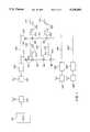
- FIG. 1shows in schematic form a topology for communication links in an electronic price display system
- FIG. 2is a perspective view of a four-foot gondola section
- FIG. 3is a side view of a vertical rail according to the invention.
- FIG. 4is a cross-sectional view of the vertical rail in greater detail
- FIG. 5is a cross sectional view of a rail and a rail fastener against a planar surface
- FIG. 6shows the rail fastener of FIG. 5 in a more detailed cross section
- FIG. 7is a cross section of the vertical rail together with a snap-on connector
- FIG. 8is a front view of the snap-on connector of FIG. 7, defining section A;
- FIG. 9is a sectional view of the snap-on connector of FIG. 8;
- FIG. 10is a rear view of the snap-on connector of FIG. 8;
- FIG. 11is a cross-section view of the vertical rail together with a cable and a cable clamp attached thereto;
- FIG. 12is a cross-sectional view of a cable clamp of FIG. 11, or of a cable cover;
- FIG. 13is a perspective view of the vertical rail system according to the invention.
- FIG. 14shows the connector 80 in side cutaway view
- FIG. 15shows the bottom view of the connector 80
- FIG. 16is a side sectional view of the connector 80.
- FIG. 17is a rear view of the connector 80.
- FIG. 1a typical topology is shown for communication links in an electronic price display system.
- the central computer or host 129is shown, of which there is typically one per store.
- Gondola controllers 128are disposed at each gondola in the store.
- the host and gondola controllersmay be hard-wired to each other, or may instead be in communication by means of low-power spread-spectrum local area network radio frequency modems, or narrow-band RF or other wireless means such as infrared. If RF modems are used, they may be conventional RF modems operating in UHF spectrum set aside for such purposes, in which case the modems 130 are physically identical, differing only in the network addresses for which they are programmed.
- Each gondola controllerhas line drivers and line receivers providing signals for horizontal bus 126 (and 126' and 126") each of which is preferably run along the tops of the gondolas.
- Each horizontal buspreferably carries a three-wire serial bus, with one wire for power, a second for ground, and a third wire for bidirectional data. This bus, as described below, is propagated to corresponding three-wire buses on the shelf rails and from there to electronic display units such as price labels.
- a typical bus design for this useis described in copending U.S. application Ser. No. 7/995,048, assigned to the same assignee as the present application.
- a technique for confining the consequences of a power line short in a shelf railis given in copending U.S. application Ser. No.
- the shelf rails 122are not wired directly to the horizontal bus 126 but are instead wired by jumpers (preferably flat cables) 100 to vertical rails 60.
- the conductors of the shelf rail 122correspond in number to the wires of the flat cable 100 of a corresponding snap-on connector 80 and are electrically connected therewith.
- each electronic price display label 123is able to exchange messages with the host 129.
- FIG. 2there is shown a perspective view of an exemplary four-foot gondola section 120.
- the sectionhas shelves 121 and behind the shelves 121 is a flat wall or planar surface 130.
- the gondola designis such as to permit a particular shelf 121 to be installed at any of numerous vertical positions, and to permit installing, removing, raising, and lowering of shelves arbitrarily often thereafter.
- a gondola controller 128is mounted on the gondola, along with a horizontal bus 126.
- Shelf rails 122are mounted to the front edges of the shelves 121, and each shelf rail 122 can accommodate a number of electronic price displays 123.
- Behind the shelves 121is a vertical rail 60.
- the lengthwise spacing of vertical rails 60 along the gondola 120may be every shelf length (here, four feet) or perhaps every other shelf length (here, every eight feet).
- Each vertical rail 60is electrically connected with the horizontal bus 126 by a jumper 127.
- each end capprovides a connection with a cable 100, preferably a flat cable.
- the flat cables 100are each terminated (preferably prior to the store installation activity) with a connector 80 which snaps onto the vertical rail 80.
- the design of the snap-on connectoris such that it serves not only for the connector 80 of the cable 100 but also as the connector between the jumper 127 and the vertical rail 60.
- the flat cables 100are preferably made with an adhesive on one side, which is protected with a removable strip.
- the horizontal bus 126is preferably a cable.
- the horizontal bus 126may optionally be selected from the same rail stock as the vertical rails 60, in which case the same snap-on connector 80 may be used between the jumper 127 and the rail 126, and at the gondola controller 128.
- the same snap-on connector 80may be used between the jumper 127 and the rail 126, and at the gondola controller 128.
- Use of a single piece part for the snap-on connectors at those locationsoffers economies.
- Use of the same rail stock for the rails 60 and 126also offers economies.
- the rail stock for the vertical rails 60(and, if desired, for the horizontal buses 126) is of constant cross section and is supplied in long lengths capable of being cut to fit on site during installation.
- the cut-to-fit capabilitypermits working with varying store designs and gondola designs. It also makes it easy, during an installation, to work around unexpected shapes and dimensions in a particular store.
- the constant cross section of the rail stockoffers yet another benefit described further below, namely that the connectors 80 may be snapped into place at quite arbitrary locations along the rail. This makes it easy to match any particular shelf location, and makes it easy to dress away any excess length of cable 100 so that it is out of harm's way.
- One way to describe the rail stockis that it comprises a mating connector for the connector 80.
- the snap-on quality of the connectors 80offers still another benefit described further below, namely that if a shelf is later to be removed or moved it is easy to unsnap the connector 80, and to replace it, if the shelf is replaced, at a position matching the new shelf position.
- FIG. 3there is shown a side view of a portion of a vertical rail 60 according to the invention.
- the rail 60is adjacent to a planar surface, not shown for clarity but disposed to the right in FIG. 3.
- the rail 60has ridges 61, one of which is visible in FIG. 3.
- Fastener 50may be seen, with tab 54 and adhesive portion 52.
- more than one fastener 50would preferably be employed, at least one of which would be in the top half of the rail and at least one of which would be in the bottom half of the rail.
- the adhesiveis selected for ready attachment to the planar surface. It is understood of course that other implementations are possible. Alternatively, other means of attachment may be used, such as screws through the tabs, without deviating in any way from the invention.
- a snap-on cover 140which is used to protect the exposed conductors of the rail from metal objects or spills.
- the coverlike the fastener, is preferably extruded from rigid PVC (polyvinyl chloride) and has substantially constant cross section.
- the fasteneris preferably cut to one-inch lengths, while the cover may be longer as needed. Since the cutting is a post-extrusion process, other lengths may readily be chosen if desired.
- the cable clamp 70not only protects the exposed conductors of the rail as does the cover, but also acts as a cable clamp for the flat cable 100. As will be described below in more detail, a ridged inner structure of the clamp 70 mates with the flat cable 100 so that the clamp is not lost when being removed or replaced.
- snap-on connector 80which provides a secure mechanical and electrical connection between the cable 100 and the rail 60.
- the connectorshown in more detail below, is capable of being removed by squeezing tabs 91.
- the cover 140, the clamp 70, the fastener 50, and the connector 80all engage reliably with the rail 60 by its ridge 61.
- the covers 140, the clamps 70, the fasteners 50, and the connectors 80 between themcover substantially all of the otherwise exposed conductors of the rail 60.
- the positioning of the connectors 80 and clamps 70is such as to dress neatly any excess in the length of flat cable 100 so that the flat cable is kept out of harm's way to the extent possible.
- FIG. 4there is shown a cross-sectional view of the vertical rail 60 in greater detail.
- the main body of the railis preferably extruded rigid PVC of constant cross section, although other materials could be used, preferably insulating materials.
- External ridges 61symmetrically disposed, secure other elements to the rail 60.
- Keying ridge feature 68is provided to prevent inadvertent snapping on of a connector backwards to the rail 60.
- Conductors 67are tin-plated metal on a mylar backing 66 which has an adhesive backing 65 already in place. It is understood that other techniques could be used to connect the conductor array and the plastic body of the rail.
- the mylar-backed flat cableis installed to the PVC body by being fed from a reel and guided into place by use of a roller or other mechanical process yielding the same effect.
- the vertical rail stock of the system according to the inventionis rigid enough to be largely self-supporting when being snaked into place on a gondola. Its constant cross section, with the absence of any pre-installed take-off points, lets it slip readily into place. Store installations are much faster than with prior art vertical cabling approaches, with attendant cost savings.
- the vertical rail stockis capable of being radiused to as tightly as 1 foot, permitting the snaking path to accommodate a variety of obstructions and constraints. The result is a rail that has the flexibility of being installed in tight spaces.
- the railmay be characterized as a flexible, semirigid rail, capable of being easily snaked or pushed into place despite obstructions from shelves and the like, thus differing substantially from many cabling systems that have to be pulled into place.
- the flexible yet semirigid characteristics of the railresult from the materials used, and the form or cross section, i.e. section modulus of the extruded stock.
- a vertical rail 60 of an insulating materialsaid rail being of substantially constant cross section along its extent, said rail having a front and a back, said rail having first and second edges along its extent and a ridge 61 along each edge, said rail having a channel in the front face and a plurality of exposed conductors 67 within the channel, the first and second edges further comprising first keying means rendering the first and second edges nonsymmetrical with respect to reflection in the plane lying therebetween.
- FIG. 5there is shown a cross sectional view of a rail 60 and a cable fastener 50 against a planar surface 130.
- Adhesive backing 52may be seen which secure the fastener 50 to the surface, and thus necessarily secure the rail 60 to the surface.
- the back of the rail 60contacts the surface 130, and the front of the rail is away from the surface.
- nothingwill lie between the fastener 50 and the channel of the rail 60 other than conductors 67 (omitted here for clarity) except, in some instances, a loop of cable 100 if folded and dressed into that space to confine any excess length of the cable 100.
- the stock used for the vertical bus 60could be used for the horizontal bus 126 as well, in which case the fasteners 50 may be used as with it as well.
- the fasteners 50may nonetheless happen to be convenient for use as cable clamps for the horizontal bus 126.
- FIG. 6shows the vertical rail fastener of FIG. 5 in a more detailed cross section.
- Internal ridges 51engage with the external ridges 61 of the rail 60.
- Tabs 54extend to the two sides, adhesive 52 (typically a double-sticky foam strip) is placed thereon, and a removable strip 53 is kept in place until the fastener is to be stuck to a wall 130.
- the fasteneris preferably extruded rigid PVC, and the adhesive backings 52 are preferably substantially coplanar to engage adhesively with a flat surface such as the wall 130.
- FIG. 7there is shown a cross section of the vertical rail 60 together with a snap-on connector 80.
- wall 130is typically at the rear of the rail 60, providing a positive support for the action of snapping the connector 80 onto the rail 60.
- FIG. 8shows the snap-on connector of FIG. 7 in front view in more detail.
- Ridges 81are shaped and positioned to engage with ridges 61 of the rail 60.
- Tabs 91may be squeezed toward each other to release the connector 80 from the rail 60.
- Abutment features 92define the spacing between the connector 80 and the conductors 67 (omitted from FIG. 8 for clarity).
- Recess 88is shaped to match keying ridge 68.
- Springy metal contacts 87are positioned to line up with the conductors 67. Barriers integrally formed in the connector lie between the contacts 87 to minimize shorts due to adjacency.
- all the features of the connector 80 visible in the view of FIG. 8are molded integrally of a single plastic, preferably high-density nylon.
- Sectional lines A in FIG. 8define the sectional view shown in FIG. 9.
- Springy contact 87is shown, which is inserted into the main body of the connector 80, and has barbs that are formed into its shaft; the barbs are compressed to slip past retention points which are molded into the plastic.
- Flat cable 100will have been stripped and inserted into the body alongside the contacts 87.
- a plastic retainer 95will have been pressed into a matching slot in the connector body.
- retainer 95is molded along with the main body of the connector.
- the retainer 95ensures both a reliable mechanical connection and a reliable electrical connection.
- retaining slotsare provided so that the flat cable 100 may be folded to 90 degrees (exiting from the right in FIG. 9) and held there by the shape of the connector. As a result, the cable 100 is dressed to run parallel to the rail 60.
- the dimensions, shape, spring constant and composition of the contacts 87are selected so as to provide a reliable tensioned contact between the connector and the conductors 67.
- the contacts 87are preferably made of phosphor bronze with tin plating or other reliable material, and may be made of the same materials as the springy contacts on the electronic price display labels 123 which make contact with the conductors of the shelf rails 122.
- each connector 80having first and second members 81 engaged with the ridges 61 of the first and second edges of the rail 60, each connector 80 further comprising springy contacts 87 corresponding in number with the plurality of exposed conductors 67 of the rail 60 and disposed in tensioned mechanical contact therewith, each connector 80 having a flat cable 100 with wires corresponding in number with the springy contacts 87 and electrically bonded therewith, each connector 80 shaped between its first and second members so as to define a keying means 88 mating with the first keying means 68.
- FIG. 10is a rear view of the snap-on connector of FIG. 8.
- Recess 88is again visible (to the left in FIG. 8, rather than to the right as in FIG. 8) as are contacts 87.
- Retainer 95is seen after it has been pressed into place. Ridges 94 are selected to be closer together than the width of cable 100.
- the cable 100may enter the connector 80 from above, and if so, then after the retainer 95 has been pressed into place the cable 100 will be folded to 90 degrees (as mentioned above) and brought out (out of the page in the view of FIG. 10) between the ridges 94 and the retainer or insert 95.
- FIG. 11is a cross-section view of the vertical rail 60 together with a cable 100 and a cable clamp 70 attached thereto.
- the relative positioning of clamp 70 and wall 130is defined by the clamp 70 having been snapped onto the rail 60, which in turn is secured to the wall 130 by fasteners 50, not visible in FIG. 11.
- the extruded stock from which the cable clamp 70 is madeis shown in more detail in FIG. 12.
- Ridges 71are shaped to fit ridges 61 on the rail.
- Inner ridges 74are located as shown, spaced 0.400 inches apart in this implementation to match the flat flexible cable 100.
- the cable clamp 70is a substantially U-shaped snap-on cable clamp, the U shape of the cable clamp 70 defining a concave side and a convex side, each cable clamp being of substantially constant cross section and shaped to fit over the rail 60, the cable clamp comprising first and second ridges 71 shaped to retain the ridges 61 of the first and second edges of the rail, the cable clamp 70 further comprising third and fourth ridges 74 located interiorly to the concave side of the cable clamp 70 and spaced to fit the flat cable 100.
- Ridges 51, 61, 71, and 81are preferably beveled as shown in the figures so that snapping parts together is easy, and so that separation of the parts is unlikely to happen inadvertently.
- FIG. 13is a perspective view of the vertical rail system according to the invention.
- Rail 60is visible, as are conductors 67.
- Two fasteners 50may be seen, and snap-on connector 80.
- Flat cable 100is retained by cable clamp 70.
- FIG. 14shows the connector 80 in side cutaway view.
- Contact 87is shown in its rest (unstressed) position prior to the connector 80 being snapped onto the rail 60, and at 87' the contact is shown when deformed after the connector 80 has been snapped onto the rail 60.
- Cable 100is shown during assembly and, at 100', it is shown after being folded to 90 degrees.
- FIG. 15shows a bottom view of the connector 80. Contacts 87 are shown, on center lines selected to match the center lines of the conductors 67 of the rail 60. Keying recess 88 and gripping ridges 81 are also visible in FIG. 15.
- FIG. 16is a side sectional view of the connector 80, corresponding in some respects with the sectional view of FIG. 9.
- Contact 87is shown in its rest (unstressed) position prior to the connector 80 being snapped onto the rail 60, and at 87' the contact is shown when deformed after the connector 80 has been snapped onto the rail 60.
- Cable 100is shown during assembly and, at 100' it is shown after being folded to 90 degrees. Insert 95 is omitted for clarity in FIG. 16.
- FIG. 17is a rear view of the connector 80, corresponding in some respects with the rear view of FIG. 10.
- the features 94may be more clearly seen, as may their role in confining cable 100 to its folded position, extending out of the page in FIG. 17.
- a shelf rail 122is mounted at the front of each shelf 121 in the store at which it is desired that electronic price display labels 123 are to be placed;
- vertical rails 60are threaded or snaked into place at the rear of the shelves 121;
- fasteners 50are snapped into place and adhesively bonded to the wall 130 of the gondola;
- each shelf rail 122its flat cable 100 is routed to the corresponding vertical rail 60, its protective strip is removed to expose its adhesive, the strip is pressed into place on the bottom of the shelf, and its snap-on connector 80 is snapped to the vertical rail 60;
- a cable clamp 70 previously fitted to the cable 100is snapped into place on the rail 60, thereby dressing the cable 100 out of harm's way, with the excess if any tucked away under covers 140 or fasteners 50;
- At least one messageis sent by electrical means from the host 129 and conveyed by the vertical rail 60 to the electronic price display label 123.
- the latter stepis done, for example, according to the protocols set forth in the previously mentioned copending applications relating to label protocols.
- the purposeis to test the installation to be sure the host is in full communication with each label.
- the installation methodprovides numerous advantages over those of prior art store price display systems. If the installation is done in a functioning store, the method according to the invention only requires removing stock from shelves in spaces 4 to 6 inches wide, a width that suffices to permit an installer to dress the flat cable into place and to snap the connector into place. This is because the dressing and snapping can be done one-handed. In prior art systems, typically the manipulations connecting the shelf cable to the vertical cable require two hands. The 4-to-6 inch opening also suffices for the manipulating and snaking of the vertical bus into place.
- the installation stepsmay be performed "blind", that is, one need not be able to see the connector snap-on location to be able to perform the associated steps. Instead, one can perform the steps while looking the other way--the flat cable exiting the connector in a particular direction naturally guides the connector into proper polarity (enhancing the protection provided by the polarization ridge 68), and the snapping in of the connector likewise can be done by feel. It will be appreciated that this also means the ambient lighting need not be perfect.
- the snap-on connector 80 corresponding to the shelf 121 to be movedis unsnapped from the vertical rail 60;
- the shelf 121is removed from the gondola 120;
- the shelf 121is moved to a new position at the gondola 120;
- the shelf 121is remounted to the gondola 120;
- the snap-on connector 80is snapped onto the vertical rail 60;
- the cable clamp 70is replaced so as to dress the cable 100 neatly;
- a messageis sent from the host 129 and conveyed via the vertical rail 60 to the electronic price display label 123 to test it.
Landscapes
- Insulated Conductors (AREA)
Abstract
Description
Claims (27)
Priority Applications (2)
| Application Number | Priority Date | Filing Date | Title |
|---|---|---|---|
| US08/045,910US5348485A (en) | 1993-04-12 | 1993-04-12 | Electronic price display system with vertical rail |
| PCT/US1994/003471WO1994024656A1 (en) | 1993-04-12 | 1994-03-24 | Electronic price display system with vertical rail |
Applications Claiming Priority (1)
| Application Number | Priority Date | Filing Date | Title |
|---|---|---|---|
| US08/045,910US5348485A (en) | 1993-04-12 | 1993-04-12 | Electronic price display system with vertical rail |
Publications (1)
| Publication Number | Publication Date |
|---|---|
| US5348485Atrue US5348485A (en) | 1994-09-20 |
Family
ID=21940496
Family Applications (1)
| Application Number | Title | Priority Date | Filing Date |
|---|---|---|---|
| US08/045,910Expired - Fee RelatedUS5348485A (en) | 1993-04-12 | 1993-04-12 | Electronic price display system with vertical rail |
Country Status (2)
| Country | Link |
|---|---|
| US (1) | US5348485A (en) |
| WO (1) | WO1994024656A1 (en) |
Cited By (131)
| Publication number | Priority date | Publication date | Assignee | Title |
|---|---|---|---|---|
| US5537312A (en)* | 1993-05-06 | 1996-07-16 | Hitachi, Ltd. | Electronic rack labeling system |
| WO1996027957A1 (en)* | 1995-03-06 | 1996-09-12 | Electronic Retailing Systems International, Inc. | Low-power two-way wireless communication system for electronic shelf labels |
| US5604923A (en)* | 1994-11-15 | 1997-02-18 | At&T Global Information Solutions Company | Electronic display system capable of displaying communication signal strength on individual electronic display modules and method of using the same |
| US5632010A (en)* | 1992-12-22 | 1997-05-20 | Electronic Retailing Systems, Inc. | Technique for communicating with electronic labels in an electronic price display system |
| WO1997020437A1 (en)* | 1995-11-30 | 1997-06-05 | Tagnology, Inc. | Electronic retail price tag system |
| US5689140A (en)* | 1994-10-14 | 1997-11-18 | Kabushiki Kaisha Toshiba | Method for forming studs and interconnects in a multi-layered semiconductor device |
| US5695261A (en)* | 1996-04-12 | 1997-12-09 | Slesinger; Bruce M. | Integrally powered modular furniture |
| US5704049A (en)* | 1992-12-22 | 1997-12-30 | Electronic Retailing Systems International Inc. | Subglobal area addressing for electronic price displays |
| US5736967A (en)* | 1993-09-03 | 1998-04-07 | Kayser Ventures, Ltd. | Article-information display system using electronically controlled tags |
| US5797132A (en)* | 1994-11-02 | 1998-08-18 | Pricer Ab | Information display system for displaying information such as pricing information on shelves containing retail merchandise |
| US5812986A (en)* | 1996-02-23 | 1998-09-22 | Danelski; Darin L. | RF light directed inventory system |
| WO1998058360A1 (en)* | 1997-06-18 | 1998-12-23 | Store Electronic Systems Communication | Electronic labelling system |
| FR2765018A1 (en)* | 1997-06-18 | 1998-12-24 | Rasec Communication Sa | Electronic label system for labelling merchandise for sale |
| FR2765017A1 (en)* | 1997-06-18 | 1998-12-24 | Rasec Communication Sa | Electronic labelling system for display of prices on supermarket shelves |
| US5943654A (en)* | 1996-12-09 | 1999-08-24 | Ncr Corporation | Method of displaying promotional messages by electronic price labels |
| US5987427A (en)* | 1997-10-30 | 1999-11-16 | Ncr Corporation | Electronic price label system including groups of electronic price labels and method of managing the groups |
| NL1009268C2 (en)* | 1998-05-27 | 1999-11-30 | Leidsche Trust En Beheermaatsc | Electronic article information system for shops. |
| US6016481A (en)* | 1992-04-30 | 2000-01-18 | Electronic Retailing Systems | Space management system |
| US6047263A (en)* | 1998-12-04 | 2000-04-04 | Ncr Corporation | Method of displaying information by an electronic price label |
| EP0913787A3 (en)* | 1997-10-30 | 2000-05-10 | Ncr International Inc. | Electronic price labels |
| US6098049A (en)* | 1997-10-30 | 2000-08-01 | Ncr Corporation | Electronic price label system including groups of electronic price labels and method of managing the groups |
| US6146158A (en)* | 1998-09-14 | 2000-11-14 | Tagnology, Inc. | Self-adjusting shelf mounted interconnect for a digital display |
| EP0765054A3 (en)* | 1995-09-25 | 2000-11-22 | NCR International, Inc. | Apparatus for wireless transmission of information in electronic display systems |
| US6181299B1 (en) | 1993-09-03 | 2001-01-30 | Display Edge Technology, Ltd. | Power and communication system for electronic display tags |
| US6199705B1 (en)* | 1998-04-24 | 2001-03-13 | Angelo Lighting, Inc. | Lighting fixture display |
| US6249263B1 (en) | 1993-09-03 | 2001-06-19 | Display Edge Technology, Ltd. | Article-information display system using electronically controlled tags |
| US6266052B1 (en) | 1993-09-03 | 2001-07-24 | Display Edge Technology, Ltd. | Power and information distribution system for article display or storage areas and related method |
| US6266905B1 (en)* | 1997-10-30 | 2001-07-31 | Ncr Corporation | Apparatus for grouping electronic price labels |
| US6269572B1 (en)* | 1997-10-30 | 2001-08-07 | Ncr Corporation | Apparatus for grouping electronic price labels |
| EP1170835A1 (en)* | 2000-07-07 | 2002-01-09 | Aioi Systems Co., Ltd. | Two-wire type wiring case |
| US6353746B1 (en)* | 1994-12-02 | 2002-03-05 | Ncr Corporation | Apparatus for improving the signal to noise ratio in wireless communication systems through message pooling |
| US6367752B1 (en) | 1999-10-20 | 2002-04-09 | Ncr Corporation | Electronic price label mounting apparatus |
| US6409132B2 (en) | 1999-04-30 | 2002-06-25 | Display Edge Technology, Ltd. | Attachment bracket for a rail |
| US20020085373A1 (en)* | 1996-04-12 | 2002-07-04 | Powerwall, Inc. | Integrally powered modular furniture |
| WO2002097932A1 (en)* | 2001-05-25 | 2002-12-05 | Möbelwerk A. Trüggelmann Gmbh & Co. Kg | Profile element with current tracks |
| US6622410B2 (en) | 1998-02-20 | 2003-09-23 | Illinois Tool Works Inc. | Attachment bracket for a shelf-edge display system |
| US6715676B1 (en) | 2000-11-28 | 2004-04-06 | Ncr Corporation | Methods and apparatus for an electronic price label system |
| US6747547B2 (en)* | 1998-06-15 | 2004-06-08 | Imbros Corporation | Communication method and apparatus improvements |
| US20040165015A1 (en)* | 2003-02-20 | 2004-08-26 | Blum Ronald D. | Electronic display device for floor advertising/messaging |
| US6782652B1 (en)* | 2003-06-13 | 2004-08-31 | Milton W. Erickson | Rail cover for use with a picatinny rail |
| US20040217167A1 (en)* | 2003-05-02 | 2004-11-04 | Huang Chun-Hui | Electronic display |
| US20050146899A1 (en)* | 2001-07-31 | 2005-07-07 | Litesnow Llc | Electrical lighting systems |
| US20050218218A1 (en)* | 2004-03-31 | 2005-10-06 | Karl Koster | Systems and methods for an electronic programmable merchandise tag |
| US20050234785A1 (en)* | 2004-04-13 | 2005-10-20 | Burman Robert F | Electronic shipping label with updateable visual display |
| US20060133994A1 (en)* | 1998-05-11 | 2006-06-22 | Dario Neri | Specific binding molecules for scintigraphy, conjugates containing them and therapeutic method for treatment of angiogenesis |
| US20070081347A1 (en)* | 2005-10-06 | 2007-04-12 | Catalina Lighting Inc. | Method and system for displaying lighting fixtures |
| US20070119795A1 (en)* | 2004-01-20 | 2007-05-31 | Goldring Peter G | Power bus for powering electronic devices operating in retail environments |
| US20070130023A1 (en)* | 2001-10-17 | 2007-06-07 | Wolinsky Robert I | System and method for providing for out-of-home advertising utilizing a satellite network |
| US20070230371A1 (en)* | 2006-03-30 | 2007-10-04 | Obopay Inc. | Data Communications Over Voice Channel With Mobile Consumer Communications Devices |
| US20070233615A1 (en)* | 2006-03-30 | 2007-10-04 | Obopay Inc. | Member-Supported Mobile Payment System |
| US20070244811A1 (en)* | 2006-03-30 | 2007-10-18 | Obopay Inc. | Mobile Client Application for Mobile Payments |
| US20070255652A1 (en)* | 2006-03-30 | 2007-11-01 | Obopay Inc. | Mobile Person-to-Person Payment System |
| US20070255662A1 (en)* | 2006-03-30 | 2007-11-01 | Obopay Inc. | Authenticating Wireless Person-to-Person Money Transfers |
| US20080032741A1 (en)* | 2006-03-30 | 2008-02-07 | Obopay | Programmable Functionalities for Mobile Consumer Communications Devices with Identification-Modules |
| US20080048880A1 (en)* | 1999-05-04 | 2008-02-28 | Intellimats, Llc | Dynamic electronic display system with brightness control |
| WO2008025879A1 (en)* | 2006-09-01 | 2008-03-06 | Upm-Kymmene Corporation | Arrangement for data display units |
| CN100388577C (en)* | 2001-12-25 | 2008-05-14 | Aioi体系有限公司 | Two-wire junction box |
| US20090119190A1 (en)* | 2006-03-30 | 2009-05-07 | Obopay Inc. | Virtual Pooled Account for Mobile Banking |
| US7613630B2 (en) | 2002-10-17 | 2009-11-03 | Automated Media Services, Inc. | System and method for editing existing footage to generate and distribute advertising content to retail locations |
| US7614065B2 (en) | 2001-12-17 | 2009-11-03 | Automated Media Services, Inc. | System and method for verifying content displayed on an electronic visual display |
| US20090287601A1 (en)* | 2008-03-14 | 2009-11-19 | Obopay, Inc. | Network-Based Viral Payment System |
| US20090314835A1 (en)* | 2008-06-23 | 2009-12-24 | United Parcel Services Of America, Inc. | System for shipping an item using an electronic envelope |
| US20090319425A1 (en)* | 2007-03-30 | 2009-12-24 | Obopay, Inc. | Mobile Person-to-Person Payment System |
| US20090319078A1 (en)* | 2008-06-23 | 2009-12-24 | United Parcel Services Of America, Inc. | Method for shipping an item using an electronic envelope |
| US20100175920A1 (en)* | 2009-01-14 | 2010-07-15 | Boston Retail Products, Inc. | System and method for distribution of electrical power |
| EP2248503A1 (en)* | 2009-05-07 | 2010-11-10 | TRUMPF Medizin Systeme GmbH + Co. KG | Medical supply unit with lockable adapters |
| US20100284731A1 (en)* | 2009-05-07 | 2010-11-11 | Trumpf Medizin Systeme Gmbh + Co. Kg | Attaching Modules to a Medical Supply Unit |
| US20120044056A1 (en)* | 2010-08-18 | 2012-02-23 | Byun Gi Young | Electronic shelf label system and communicating method using the same |
| US20120228240A1 (en)* | 2011-03-08 | 2012-09-13 | T-Ink, Llc | Intelligent Display And Fixture System |
| US8479422B1 (en)* | 2004-12-07 | 2013-07-09 | Ncr Corporation | Electronic shelf label with internal information |
| US20130299439A1 (en)* | 2012-05-09 | 2013-11-14 | Maf Technologies Corporation | Powering Assembly and Method For Adjustable Shelving |
| CN103565177A (en)* | 2012-08-08 | 2014-02-12 | 孙业扬 | Low voltage plug, i.e., play display system |
| US20140077489A1 (en)* | 2009-11-12 | 2014-03-20 | Whirlpool Corporation | Adjustable connector system for connection to a modular appliance |
| US8762212B2 (en) | 1995-07-31 | 2014-06-24 | Information Planning & Management Service, Inc. | Electronic product information display system |
| US20140210692A1 (en)* | 2013-01-25 | 2014-07-31 | Opticon, Inc. | System for remote management of electronic shelf display modules |
| US20140218896A1 (en)* | 2009-04-23 | 2014-08-07 | POP Displays USA LLC | Display Assembly Carrier Tray |
| US20140220833A1 (en)* | 2013-02-07 | 2014-08-07 | Whirlpool Corporation | Electrical connector for adjustable refrigerator shelf |
| US20140227893A1 (en)* | 2013-02-14 | 2014-08-14 | L & P Property Management Company | Power-supply device that provides power to a shelving system |
| EP2768085A1 (en) | 2013-02-19 | 2014-08-20 | Phoenix Contact Development & Manufacturing, Inc. | Shelf lighting connector assembly |
| US20140349502A1 (en)* | 2011-12-14 | 2014-11-27 | Dula-Werke Dustmann & Co. Gmbh | Device for supplying electrical energy to a load, and system therefor |
| ITBO20130414A1 (en)* | 2013-07-31 | 2015-02-01 | Cefla Coop | REINFORCED FLOORS FOR METAL SHELVES, SUITABLE FOR SUPPORTING THE ELECTRONIC LABELS AND / OR OTHER PERIPHERALS AND ITS MANUFACTURING PROCEDURE |
| EP2833490A1 (en) | 2013-07-31 | 2015-02-04 | Cefla Societa' Cooperativa | Electrified rail, particularly for powering metal shelving units, and method for its manufacturing |
| US20150079823A1 (en)* | 2013-09-16 | 2015-03-19 | Streater LLC | Electrical Assembly for Connecting Components of a Lighting System for Illuminating Store Shelving |
| US20150173528A1 (en)* | 2013-12-23 | 2015-06-25 | Wal-Mart Stores, Inc. | Modular wall assembly for a cosmetic fixture system |
| US20150201762A1 (en)* | 2012-09-03 | 2015-07-23 | Visplay International Ag | Suspension Device For Presenting Goods, Having A Current-Carrying Profiled Rail And Primary Support Which Can Be Hung Therein |
| US9130327B2 (en) | 2013-06-18 | 2015-09-08 | Trinity, Llc | Power assembly for display |
| WO2016087631A1 (en)* | 2014-12-05 | 2016-06-09 | Vitrinemedia | Luminous display panel |
| US9367851B2 (en) | 2009-09-17 | 2016-06-14 | Information Planning & Management Service, Inc. | System and method for managing compliance with retail display regulations across a plurality of jurisdictions |
| US9404645B1 (en)* | 2015-09-16 | 2016-08-02 | Elemental LED, Inc. | Wiring and connection management system for installation of LED light engines |
| US9418267B1 (en)* | 2015-08-10 | 2016-08-16 | Ground Star Llc | Modular RFID shelving |
| US9446908B2 (en) | 2012-02-05 | 2016-09-20 | Matthews Resources, Inc. | Conveying systems and methods of associating data with an item transported by a conveying system |
| US20160327222A1 (en)* | 2013-03-14 | 2016-11-10 | Apex Technologies, Inc. | Suspended Track and Planar Electrode Systems and Methods |
| US20160344135A1 (en)* | 2015-05-22 | 2016-11-24 | Sunrise R&D Holdings, Llc | Modular shelving systems, magnetic electrical connectors, conductor assemblies, and mounting inserts |
| US9541328B2 (en) | 2013-02-07 | 2017-01-10 | Whirlpool Corporation | Power supplies for lighted shelves in a refrigerator |
| US20170033521A1 (en)* | 2013-11-21 | 2017-02-02 | Elmer A. Wessel | Power Assembly |
| US20170035524A1 (en)* | 2014-04-30 | 2017-02-09 | Maquet (Suzhou) Co., Ltd. | Medical pendant having an electric interface |
| WO2017033010A1 (en)* | 2015-08-24 | 2017-03-02 | Sfd Systems Limited | Connector system |
| ITUB20154261A1 (en)* | 2015-10-09 | 2017-04-09 | Cefla S C | REINFORCED METAL SHELF PLATES PROVIDED WITH OPENINGS FOR THE PASSAGE AND SUPPORT OF ELECTRIC CABLES |
| US9775447B2 (en) | 2011-03-08 | 2017-10-03 | Dci Marketing, Inc. | Illuminated shelving |
| US9883756B2 (en)* | 2013-12-18 | 2018-02-06 | Juvema Ag | Rack system having an electrical supply |
| US20180092472A1 (en)* | 2016-10-05 | 2018-04-05 | Ariel Haroush | Modular powered secure product display mount |
| DE102016124956A1 (en)* | 2016-12-20 | 2018-06-21 | Rehau Ag + Co | System for supplying a plurality of electronic display devices for displaying product-related information and goods presentation system |
| US20180268745A1 (en)* | 2016-12-28 | 2018-09-20 | Opticon Sensors Europe B.V. | Electronic shelf label system |
| US10130196B2 (en) | 2014-08-07 | 2018-11-20 | Artform International Limited | Product display shelf, system and method |
| US20180366041A1 (en)* | 2015-12-15 | 2018-12-20 | Lg Innotek Co., Ltd. | Communication device and electronic device comprising the same |
| US10229383B2 (en) | 2012-02-05 | 2019-03-12 | Matthews International Corporation | Perpetual batch order fulfillment |
| CN109888581A (en)* | 2019-04-28 | 2019-06-14 | 苏州市华仓塑料有限公司 | A kind of eye-splice-type takes the external track power supply system of electricity |
| US10405674B2 (en) | 2016-03-23 | 2019-09-10 | Retail Space Solutions Llc | Low product indicator for self facing merchandiser and related methods |
| US10432001B1 (en)* | 2018-05-29 | 2019-10-01 | Vanessa Bellis | Stackable shelf system for charging electrical devices |
| US10477988B2 (en)* | 2017-03-30 | 2019-11-19 | Walmart Apollo, Llc | Tape for modular shelf system |
| US20190380486A1 (en)* | 2016-11-23 | 2019-12-19 | Shanghai Eyemove Image Printing Co., Ltd. | Bracket connection structure and bracket |
| US20200052438A1 (en)* | 2018-08-08 | 2020-02-13 | Hyperframe Inc. | Framing assembly with modular connectors |
| WO2020051494A1 (en)* | 2018-09-07 | 2020-03-12 | Adroit Worldwide Media, Inc. | Electronic shelving systems, cable-managing coupling brackets, and methods thereof |
| US10646058B2 (en)* | 2018-07-09 | 2020-05-12 | Vira Insight, Llc | Retail display system with power supply interface |
| US10680383B2 (en) | 2013-03-14 | 2020-06-09 | Apex Technologies, Inc. | Linear electrode systems for module attachment with non-uniform axial spacing |
| US10702076B2 (en) | 2016-01-18 | 2020-07-07 | Atlas Bolt & Screw Company Llc | Sensors, devices, adapters and mating structures for merchandisers and related methods |
| WO2020150794A1 (en)* | 2019-01-23 | 2020-07-30 | Gomes Jonas Da Silva | Main and secondary electronic tag and installation thereof on gondolas in commercial establishments for a system for the remote updating of information in real time and management using dedicated software |
| US20200245785A1 (en)* | 2019-02-01 | 2020-08-06 | Xerox Corporation | Point-of-purchase (pop) display |
| CN112271511A (en)* | 2020-10-10 | 2021-01-26 | 赛尔富电子有限公司 | Power taking head and power taking device with same |
| US20210076529A1 (en)* | 2018-03-12 | 2021-03-11 | Zonit Structured Solutions, Llc | Management module, z-strip, and mini-ats systems and related components |
| US10952548B2 (en) | 2016-10-18 | 2021-03-23 | Retail Space Solutions Llc | Illuminated merchandiser, retrofit kit and related methods |
| US11091958B2 (en)* | 2018-01-10 | 2021-08-17 | Sub-Zero Group, Inc. | Shelf electrical signal connector |
| US11223172B2 (en)* | 2019-08-23 | 2022-01-11 | Self Electronics Co., Ltd. | Embedded electrical supply plug, electrical supply support arm, and rack electrical supply system |
| US11221175B1 (en) | 2020-12-18 | 2022-01-11 | Sub-Zero Group, Inc. | Liner hanger |
| US11296433B1 (en) | 2019-10-15 | 2022-04-05 | Sub-Zero Group, Inc. | Shelf with electrical connectivity |
| US11440743B2 (en) | 2010-07-29 | 2022-09-13 | Matthews International Corporation | Networked motorized drive roller conveyor |
| US20220360066A1 (en)* | 2021-05-04 | 2022-11-10 | Walmart Apollo, Llc | Adjustable power shelf system |
| US11555649B2 (en)* | 2016-12-12 | 2023-01-17 | Bsh Hausgeraete Gmbh | Electrical appliance having electric devices in a distributed arrangement |
| US11592879B2 (en)* | 2019-07-26 | 2023-02-28 | Artitalia Group Inc. | Modular back panel assembly for a display structure |
| US20230148748A1 (en)* | 2021-11-12 | 2023-05-18 | Vidir Solutions Inc. | Storage system with movable platforms and internal electrical power distribution system |
| WO2025108538A1 (en)* | 2023-11-22 | 2025-05-30 | Ses-Imagotag Gmbh | Electronic shelf rail system having shelf rail and supply apparatus |
Citations (32)
| Publication number | Priority date | Publication date | Assignee | Title |
|---|---|---|---|---|
| US2108031A (en)* | 1937-01-06 | 1938-02-15 | Acuff Henry Cecil | Electrical connecting device |
| US2822631A (en)* | 1957-02-12 | 1958-02-11 | Gordon R Lynch | Changeable price tags and holder therefor |
| US3044035A (en)* | 1958-02-10 | 1962-07-10 | Jr Thomas C Adams | Continuous electrical connection |
| US3718816A (en)* | 1970-06-18 | 1973-02-27 | Reininghaus & Co | Illumination device |
| US3894170A (en)* | 1972-12-20 | 1975-07-08 | Rehau Plastiks | Combined insulating strip and electrical conductor and conductor support assembly including the same |
| US4002886A (en)* | 1975-06-20 | 1977-01-11 | Ronald Murl Sundelin | Electronic price display unit |
| US4029378A (en)* | 1976-03-11 | 1977-06-14 | Itt Industries, Inc. | Electrified channel with corresponding snap acting connector |
| US4082393A (en)* | 1977-01-27 | 1978-04-04 | Westinghouse Electric Corporation | Bus duct assembly |
| US4108523A (en)* | 1977-05-25 | 1978-08-22 | Itt Industries, Incorporated | Electrified channel, equipped with a snap-acting connector |
| US4346453A (en)* | 1979-11-26 | 1982-08-24 | Scope Incorporated | Item display order picking system |
| US4500880A (en)* | 1981-07-06 | 1985-02-19 | Motorola, Inc. | Real time, computer-driven retail pricing display system |
| GB2197564A (en)* | 1986-09-22 | 1988-05-18 | Telepanel Inc | Radio broadcast communication systems |
| US4766295A (en)* | 1987-03-02 | 1988-08-23 | H.E. Butt Grocery Company | Electronic pricing display system |
| US4783740A (en)* | 1985-12-26 | 1988-11-08 | Kabushiki Kaisha Toshiba | Inventory management system |
| EP0299355A2 (en)* | 1987-07-15 | 1989-01-18 | Zellweger Telecommunications AG | Price display system for sales areas and/or windows |
| US4812134A (en)* | 1988-05-23 | 1989-03-14 | Miller Ruth E | Wall mounted lighting track system |
| US4888709A (en)* | 1987-03-27 | 1989-12-19 | Viscom Systems, Inc. | Electronic product information display system |
| US4907137A (en)* | 1987-05-30 | 1990-03-06 | Rolf Winter | Apparatus for supporting a lamp on a low-voltage rail |
| US4939861A (en)* | 1987-12-28 | 1990-07-10 | Telepanel, Inc. | Shelf tag moulding attachment assembly |
| GB2228812A (en)* | 1986-09-22 | 1990-09-05 | Telepanel Inc | Retail store electronic shelf microprocessor module |
| US4962466A (en)* | 1987-03-27 | 1990-10-09 | Viscom Systems, Inc. | Electronic product information display system |
| EP0396414A2 (en)* | 1989-05-05 | 1990-11-07 | Pricelink, Inc. | Information display system |
| US5008493A (en)* | 1988-04-06 | 1991-04-16 | Hans Wagener | Holder with busbars for a busbar system |
| EP0428055A2 (en)* | 1989-11-15 | 1991-05-22 | Neste Oy | Conductor rail |
| US5019811A (en)* | 1984-10-15 | 1991-05-28 | Unigrafic Ag | Device for marking edges of shelves |
| US5111196A (en)* | 1987-03-23 | 1992-05-05 | Esl, Inc. | Electronic information display module and connector therefor |
| US5172314A (en)* | 1991-05-03 | 1992-12-15 | Electronic Retailing Systems International | Apparatus for communicating price changes including printer and display devices |
| WO1993005456A1 (en)* | 1991-09-10 | 1993-03-18 | Electronic Retailing Systems International | Localizing power faults in an electronic pricing display system |
| WO1993005475A1 (en)* | 1991-09-10 | 1993-03-18 | Electronic Retailing Systems International, Inc. | System for displaying prices |
| US5198644A (en)* | 1989-05-05 | 1993-03-30 | Diablo Research Corporation | System for display of prices and related method |
| US5241467A (en)* | 1992-04-30 | 1993-08-31 | Ers Associates Limited Partnership | Space management system |
| US5245534A (en)* | 1991-09-10 | 1993-09-14 | Ers Associates Limited Partnership | Electronic tag location systems |
Family Cites Families (2)
| Publication number | Priority date | Publication date | Assignee | Title |
|---|---|---|---|---|
| GB8426357D0 (en)* | 1984-10-18 | 1984-11-21 | Weidmueller C A Gmbh Co | Electrical conductor system |
| FR2607976A1 (en)* | 1986-12-04 | 1988-06-10 | Renault | Multiplexing electrical connection device for a motor vehicle |
- 1993
- 1993-04-12USUS08/045,910patent/US5348485A/ennot_activeExpired - Fee Related
- 1994
- 1994-03-24WOPCT/US1994/003471patent/WO1994024656A1/enactiveApplication Filing
Patent Citations (33)
| Publication number | Priority date | Publication date | Assignee | Title |
|---|---|---|---|---|
| US2108031A (en)* | 1937-01-06 | 1938-02-15 | Acuff Henry Cecil | Electrical connecting device |
| US2822631A (en)* | 1957-02-12 | 1958-02-11 | Gordon R Lynch | Changeable price tags and holder therefor |
| US3044035A (en)* | 1958-02-10 | 1962-07-10 | Jr Thomas C Adams | Continuous electrical connection |
| US3718816A (en)* | 1970-06-18 | 1973-02-27 | Reininghaus & Co | Illumination device |
| US3894170A (en)* | 1972-12-20 | 1975-07-08 | Rehau Plastiks | Combined insulating strip and electrical conductor and conductor support assembly including the same |
| US4002886A (en)* | 1975-06-20 | 1977-01-11 | Ronald Murl Sundelin | Electronic price display unit |
| US4029378A (en)* | 1976-03-11 | 1977-06-14 | Itt Industries, Inc. | Electrified channel with corresponding snap acting connector |
| US4082393A (en)* | 1977-01-27 | 1978-04-04 | Westinghouse Electric Corporation | Bus duct assembly |
| US4108523A (en)* | 1977-05-25 | 1978-08-22 | Itt Industries, Incorporated | Electrified channel, equipped with a snap-acting connector |
| US4346453A (en)* | 1979-11-26 | 1982-08-24 | Scope Incorporated | Item display order picking system |
| US4500880A (en)* | 1981-07-06 | 1985-02-19 | Motorola, Inc. | Real time, computer-driven retail pricing display system |
| US5019811A (en)* | 1984-10-15 | 1991-05-28 | Unigrafic Ag | Device for marking edges of shelves |
| US4783740A (en)* | 1985-12-26 | 1988-11-08 | Kabushiki Kaisha Toshiba | Inventory management system |
| US4821291A (en)* | 1986-09-22 | 1989-04-11 | Stevens John K | Improvements in or relating to signal communication systems |
| GB2228812A (en)* | 1986-09-22 | 1990-09-05 | Telepanel Inc | Retail store electronic shelf microprocessor module |
| GB2197564A (en)* | 1986-09-22 | 1988-05-18 | Telepanel Inc | Radio broadcast communication systems |
| US4766295A (en)* | 1987-03-02 | 1988-08-23 | H.E. Butt Grocery Company | Electronic pricing display system |
| US5111196A (en)* | 1987-03-23 | 1992-05-05 | Esl, Inc. | Electronic information display module and connector therefor |
| US4888709A (en)* | 1987-03-27 | 1989-12-19 | Viscom Systems, Inc. | Electronic product information display system |
| US4962466A (en)* | 1987-03-27 | 1990-10-09 | Viscom Systems, Inc. | Electronic product information display system |
| US4907137A (en)* | 1987-05-30 | 1990-03-06 | Rolf Winter | Apparatus for supporting a lamp on a low-voltage rail |
| EP0299355A2 (en)* | 1987-07-15 | 1989-01-18 | Zellweger Telecommunications AG | Price display system for sales areas and/or windows |
| US4939861A (en)* | 1987-12-28 | 1990-07-10 | Telepanel, Inc. | Shelf tag moulding attachment assembly |
| US5008493A (en)* | 1988-04-06 | 1991-04-16 | Hans Wagener | Holder with busbars for a busbar system |
| US4812134A (en)* | 1988-05-23 | 1989-03-14 | Miller Ruth E | Wall mounted lighting track system |
| EP0396414A2 (en)* | 1989-05-05 | 1990-11-07 | Pricelink, Inc. | Information display system |
| US5198644A (en)* | 1989-05-05 | 1993-03-30 | Diablo Research Corporation | System for display of prices and related method |
| EP0428055A2 (en)* | 1989-11-15 | 1991-05-22 | Neste Oy | Conductor rail |
| US5172314A (en)* | 1991-05-03 | 1992-12-15 | Electronic Retailing Systems International | Apparatus for communicating price changes including printer and display devices |
| WO1993005456A1 (en)* | 1991-09-10 | 1993-03-18 | Electronic Retailing Systems International | Localizing power faults in an electronic pricing display system |
| WO1993005475A1 (en)* | 1991-09-10 | 1993-03-18 | Electronic Retailing Systems International, Inc. | System for displaying prices |
| US5245534A (en)* | 1991-09-10 | 1993-09-14 | Ers Associates Limited Partnership | Electronic tag location systems |
| US5241467A (en)* | 1992-04-30 | 1993-08-31 | Ers Associates Limited Partnership | Space management system |
Cited By (233)
| Publication number | Priority date | Publication date | Assignee | Title |
|---|---|---|---|---|
| US6016481A (en)* | 1992-04-30 | 2000-01-18 | Electronic Retailing Systems | Space management system |
| US5704049A (en)* | 1992-12-22 | 1997-12-30 | Electronic Retailing Systems International Inc. | Subglobal area addressing for electronic price displays |
| US5864325A (en)* | 1992-12-22 | 1999-01-26 | Electronic Retailing Systems International, Inc. | Technique for communicating with electronic labels in an electronic price display system |
| US5632010A (en)* | 1992-12-22 | 1997-05-20 | Electronic Retailing Systems, Inc. | Technique for communicating with electronic labels in an electronic price display system |
| US5977998A (en)* | 1992-12-22 | 1999-11-02 | Electronic Retailing Systems International, Inc. | Technique for communicating with electronic labels in an electronic price display system |
| US5537312A (en)* | 1993-05-06 | 1996-07-16 | Hitachi, Ltd. | Electronic rack labeling system |
| US6271807B1 (en) | 1993-09-03 | 2001-08-07 | Display Edge Technology, Ltd. | Method of initializing, controlling and updating electronic display tags and related controller therefor |
| US5736967A (en)* | 1993-09-03 | 1998-04-07 | Kayser Ventures, Ltd. | Article-information display system using electronically controlled tags |
| US6181299B1 (en) | 1993-09-03 | 2001-01-30 | Display Edge Technology, Ltd. | Power and communication system for electronic display tags |
| US6266052B1 (en) | 1993-09-03 | 2001-07-24 | Display Edge Technology, Ltd. | Power and information distribution system for article display or storage areas and related method |
| US6249263B1 (en) | 1993-09-03 | 2001-06-19 | Display Edge Technology, Ltd. | Article-information display system using electronically controlled tags |
| EP0787339A4 (en)* | 1994-09-21 | 1999-01-07 | Display Edge Technology Ltd | Article-information display system using electronically controlled tags |
| US5689140A (en)* | 1994-10-14 | 1997-11-18 | Kabushiki Kaisha Toshiba | Method for forming studs and interconnects in a multi-layered semiconductor device |
| US5797132A (en)* | 1994-11-02 | 1998-08-18 | Pricer Ab | Information display system for displaying information such as pricing information on shelves containing retail merchandise |
| US5604923A (en)* | 1994-11-15 | 1997-02-18 | At&T Global Information Solutions Company | Electronic display system capable of displaying communication signal strength on individual electronic display modules and method of using the same |
| US6353746B1 (en)* | 1994-12-02 | 2002-03-05 | Ncr Corporation | Apparatus for improving the signal to noise ratio in wireless communication systems through message pooling |
| US6108367A (en)* | 1995-03-06 | 2000-08-22 | Electronic Retailing Systems, Inc. | Low power two-way wireless communication system for electronic shelf labels |
| WO1996027957A1 (en)* | 1995-03-06 | 1996-09-12 | Electronic Retailing Systems International, Inc. | Low-power two-way wireless communication system for electronic shelf labels |
| US8762212B2 (en) | 1995-07-31 | 2014-06-24 | Information Planning & Management Service, Inc. | Electronic product information display system |
| US8910864B2 (en) | 1995-07-31 | 2014-12-16 | Information Planning & Management Service, Inc. | Electronic product information display system |
| EP0765054A3 (en)* | 1995-09-25 | 2000-11-22 | NCR International, Inc. | Apparatus for wireless transmission of information in electronic display systems |
| US6791466B1 (en) | 1995-09-25 | 2004-09-14 | Ncr Corporation | Apparatus for providing wireless transmission of information in electronic display systems and methods of using the same |
| WO1997020437A1 (en)* | 1995-11-30 | 1997-06-05 | Tagnology, Inc. | Electronic retail price tag system |
| EP0864232A4 (en)* | 1995-11-30 | 2002-02-20 | Tagnology Inc | Electronic retail price tag system |
| US6570492B1 (en) | 1995-11-30 | 2003-05-27 | Sergio Peratoner | Electronic retail price tag system |
| US5812986A (en)* | 1996-02-23 | 1998-09-22 | Danelski; Darin L. | RF light directed inventory system |
| US5695261A (en)* | 1996-04-12 | 1997-12-09 | Slesinger; Bruce M. | Integrally powered modular furniture |
| US20020085373A1 (en)* | 1996-04-12 | 2002-07-04 | Powerwall, Inc. | Integrally powered modular furniture |
| US5943654A (en)* | 1996-12-09 | 1999-08-24 | Ncr Corporation | Method of displaying promotional messages by electronic price labels |
| FR2765019A1 (en)* | 1997-06-18 | 1998-12-24 | Label 41 | ELECTRONIC LABELING SYSTEM |
| FR2765018A1 (en)* | 1997-06-18 | 1998-12-24 | Rasec Communication Sa | Electronic label system for labelling merchandise for sale |
| WO1998058360A1 (en)* | 1997-06-18 | 1998-12-23 | Store Electronic Systems Communication | Electronic labelling system |
| FR2765017A1 (en)* | 1997-06-18 | 1998-12-24 | Rasec Communication Sa | Electronic labelling system for display of prices on supermarket shelves |
| US6418651B1 (en) | 1997-06-18 | 2002-07-16 | Store Electronic Systems Communication | Electronic labeling system |
| US6269572B1 (en)* | 1997-10-30 | 2001-08-07 | Ncr Corporation | Apparatus for grouping electronic price labels |
| EP0913787A3 (en)* | 1997-10-30 | 2000-05-10 | Ncr International Inc. | Electronic price labels |
| US6568111B2 (en)* | 1997-10-30 | 2003-05-27 | Ncr Corporation | Apparatus for grouping electronic price labels |
| US6266905B1 (en)* | 1997-10-30 | 2001-07-31 | Ncr Corporation | Apparatus for grouping electronic price labels |
| US6581316B2 (en)* | 1997-10-30 | 2003-06-24 | Ncr Corporation | Apparatus for grouping electronic price labels |
| US5987427A (en)* | 1997-10-30 | 1999-11-16 | Ncr Corporation | Electronic price label system including groups of electronic price labels and method of managing the groups |
| US6098049A (en)* | 1997-10-30 | 2000-08-01 | Ncr Corporation | Electronic price label system including groups of electronic price labels and method of managing the groups |
| US6622410B2 (en) | 1998-02-20 | 2003-09-23 | Illinois Tool Works Inc. | Attachment bracket for a shelf-edge display system |
| US6199705B1 (en)* | 1998-04-24 | 2001-03-13 | Angelo Lighting, Inc. | Lighting fixture display |
| US20060133994A1 (en)* | 1998-05-11 | 2006-06-22 | Dario Neri | Specific binding molecules for scintigraphy, conjugates containing them and therapeutic method for treatment of angiogenesis |
| WO1999062045A1 (en)* | 1998-05-27 | 1999-12-02 | Leidsche Trust- En Beheermaatschappij | Electronic article information system for shops |
| NL1009268C2 (en)* | 1998-05-27 | 1999-11-30 | Leidsche Trust En Beheermaatsc | Electronic article information system for shops. |
| USRE43848E1 (en)* | 1998-06-15 | 2012-12-11 | VSIM Patent Co, LLC | Communication method and apparatus improvements |
| US6747547B2 (en)* | 1998-06-15 | 2004-06-08 | Imbros Corporation | Communication method and apparatus improvements |
| US6146158A (en)* | 1998-09-14 | 2000-11-14 | Tagnology, Inc. | Self-adjusting shelf mounted interconnect for a digital display |
| US6047263A (en)* | 1998-12-04 | 2000-04-04 | Ncr Corporation | Method of displaying information by an electronic price label |
| US6409132B2 (en) | 1999-04-30 | 2002-06-25 | Display Edge Technology, Ltd. | Attachment bracket for a rail |
| US7629896B2 (en) | 1999-05-04 | 2009-12-08 | Intellimat, Inc. | Floor display system with interactive features and variable image rotation |
| US7511630B2 (en) | 1999-05-04 | 2009-03-31 | Intellimat, Inc. | Dynamic electronic display system with brightness control |
| US20080055105A1 (en)* | 1999-05-04 | 2008-03-06 | Intellimat, Inc. | Floor display system with interactive features and variable image rotation |
| US20080048880A1 (en)* | 1999-05-04 | 2008-02-28 | Intellimats, Llc | Dynamic electronic display system with brightness control |
| US6367752B1 (en) | 1999-10-20 | 2002-04-09 | Ncr Corporation | Electronic price label mounting apparatus |
| US6435884B1 (en) | 2000-07-07 | 2002-08-20 | Aioi Systems, Co., Ltd. | Two-wire type wiring case |
| EP1170835A1 (en)* | 2000-07-07 | 2002-01-09 | Aioi Systems Co., Ltd. | Two-wire type wiring case |
| US6715676B1 (en) | 2000-11-28 | 2004-04-06 | Ncr Corporation | Methods and apparatus for an electronic price label system |
| US6835075B2 (en) | 2001-05-25 | 2004-12-28 | Mobelwerk A. Truggelmann Gmbh & Co. Kg | Profile member with current rail |
| WO2002097932A1 (en)* | 2001-05-25 | 2002-12-05 | Möbelwerk A. Trüggelmann Gmbh & Co. Kg | Profile element with current tracks |
| US20050146899A1 (en)* | 2001-07-31 | 2005-07-07 | Litesnow Llc | Electrical lighting systems |
| US7742950B2 (en) | 2001-10-17 | 2010-06-22 | Automated Media Services, Inc. | System and method for providing for out-of-home advertising utilizing a satellite network |
| US7912759B2 (en) | 2001-10-17 | 2011-03-22 | Automated Media Services, Inc. | Method for providing a retailer with out-of-home advertising capabilities |
| US20070130023A1 (en)* | 2001-10-17 | 2007-06-07 | Wolinsky Robert I | System and method for providing for out-of-home advertising utilizing a satellite network |
| US8315913B2 (en) | 2001-10-17 | 2012-11-20 | Automated Media Services, Inc. | System and method for determining physical location of electronic display devices in a retail establishment |
| US7937723B2 (en) | 2001-12-17 | 2011-05-03 | Automated Media Services, Inc. | System and method for verifying content displayed on an electronic visual display by measuring an operational parameter of the electronic visual display while displaying the content |
| US7614065B2 (en) | 2001-12-17 | 2009-11-03 | Automated Media Services, Inc. | System and method for verifying content displayed on an electronic visual display |
| CN100388577C (en)* | 2001-12-25 | 2008-05-14 | Aioi体系有限公司 | Two-wire junction box |
| US7613630B2 (en) | 2002-10-17 | 2009-11-03 | Automated Media Services, Inc. | System and method for editing existing footage to generate and distribute advertising content to retail locations |
| US20060087501A1 (en)* | 2003-02-20 | 2006-04-27 | Blum Ronald D | Electronic display device with separately articulated portions for floor advertising/messaging |
| US20040165015A1 (en)* | 2003-02-20 | 2004-08-26 | Blum Ronald D. | Electronic display device for floor advertising/messaging |
| US6964371B2 (en)* | 2003-05-02 | 2005-11-15 | Atop Technologies Inc. | Electronic display |
| US20040217167A1 (en)* | 2003-05-02 | 2004-11-04 | Huang Chun-Hui | Electronic display |
| US6782652B1 (en)* | 2003-06-13 | 2004-08-31 | Milton W. Erickson | Rail cover for use with a picatinny rail |
| US20070119795A1 (en)* | 2004-01-20 | 2007-05-31 | Goldring Peter G | Power bus for powering electronic devices operating in retail environments |
| US7520429B2 (en)* | 2004-03-31 | 2009-04-21 | United Parcel Service Of America, Inc. | Systems and methods for an electronic programmable merchandise tag |
| US20050218218A1 (en)* | 2004-03-31 | 2005-10-06 | Karl Koster | Systems and methods for an electronic programmable merchandise tag |
| US20050237203A1 (en)* | 2004-04-13 | 2005-10-27 | Burman Robert F | Electronic shipping label with updateable visual display |
| US7511617B2 (en) | 2004-04-13 | 2009-03-31 | United Parcel Service Of America, Inc. | Electronic shipping label with updateable visual display |
| US20050234785A1 (en)* | 2004-04-13 | 2005-10-20 | Burman Robert F | Electronic shipping label with updateable visual display |
| US20050237204A1 (en)* | 2004-04-13 | 2005-10-27 | Burman Robert F | Electronic shipping label with updateable visual display |
| US7574366B2 (en) | 2004-04-13 | 2009-08-11 | United Parcel Service Of America, Inc. | Electronic shipping label with updateable visual display |
| US7580845B2 (en) | 2004-04-13 | 2009-08-25 | United Parcel Services Of America, Inc. | Electronic shipping label with updateable visual display |
| US8479422B1 (en)* | 2004-12-07 | 2013-07-09 | Ncr Corporation | Electronic shelf label with internal information |
| US7249872B2 (en)* | 2005-10-06 | 2007-07-31 | Catalina Lighting Inc. | Method and system for displaying lighting fixtures |
| US20070081347A1 (en)* | 2005-10-06 | 2007-04-12 | Catalina Lighting Inc. | Method and system for displaying lighting fixtures |
| US20070255662A1 (en)* | 2006-03-30 | 2007-11-01 | Obopay Inc. | Authenticating Wireless Person-to-Person Money Transfers |
| US8532021B2 (en) | 2006-03-30 | 2013-09-10 | Obopay, Inc. | Data communications over voice channel with mobile consumer communications devices |
| US20090119190A1 (en)* | 2006-03-30 | 2009-05-07 | Obopay Inc. | Virtual Pooled Account for Mobile Banking |
| US20070244811A1 (en)* | 2006-03-30 | 2007-10-18 | Obopay Inc. | Mobile Client Application for Mobile Payments |
| US20070255653A1 (en)* | 2006-03-30 | 2007-11-01 | Obopay Inc. | Mobile Person-to-Person Payment System |
| US20070233615A1 (en)* | 2006-03-30 | 2007-10-04 | Obopay Inc. | Member-Supported Mobile Payment System |
| US20080032741A1 (en)* | 2006-03-30 | 2008-02-07 | Obopay | Programmable Functionalities for Mobile Consumer Communications Devices with Identification-Modules |
| US20070255652A1 (en)* | 2006-03-30 | 2007-11-01 | Obopay Inc. | Mobile Person-to-Person Payment System |
| US8249965B2 (en) | 2006-03-30 | 2012-08-21 | Obopay, Inc. | Member-supported mobile payment system |
| US20070230371A1 (en)* | 2006-03-30 | 2007-10-04 | Obopay Inc. | Data Communications Over Voice Channel With Mobile Consumer Communications Devices |
| US20070255620A1 (en)* | 2006-03-30 | 2007-11-01 | Obopay Inc. | Transacting Mobile Person-to-Person Payments |
| US7873573B2 (en) | 2006-03-30 | 2011-01-18 | Obopay, Inc. | Virtual pooled account for mobile banking |
| WO2008025879A1 (en)* | 2006-09-01 | 2008-03-06 | Upm-Kymmene Corporation | Arrangement for data display units |
| US20090319425A1 (en)* | 2007-03-30 | 2009-12-24 | Obopay, Inc. | Mobile Person-to-Person Payment System |
| US20090287601A1 (en)* | 2008-03-14 | 2009-11-19 | Obopay, Inc. | Network-Based Viral Payment System |
| US20090319078A1 (en)* | 2008-06-23 | 2009-12-24 | United Parcel Services Of America, Inc. | Method for shipping an item using an electronic envelope |
| US20090314835A1 (en)* | 2008-06-23 | 2009-12-24 | United Parcel Services Of America, Inc. | System for shipping an item using an electronic envelope |
| US20170288377A1 (en)* | 2009-01-14 | 2017-10-05 | Lawrence A. Ellis | System and method for distribution of electrical power |
| US20100175919A1 (en)* | 2009-01-14 | 2010-07-15 | Boston Retail Products, Inc. | System and method for distribution of electrical power |
| US20100175920A1 (en)* | 2009-01-14 | 2010-07-15 | Boston Retail Products, Inc. | System and method for distribution of electrical power |
| US9629481B2 (en)* | 2009-04-23 | 2017-04-25 | Pop Displays Usa, Llc | Display assembly support with low voltage bus |
| US20140218896A1 (en)* | 2009-04-23 | 2014-08-07 | POP Displays USA LLC | Display Assembly Carrier Tray |
| US20170202370A1 (en)* | 2009-04-23 | 2017-07-20 | POP Displays USA LLC | Display Assembly |
| CN101889899B (en)* | 2009-05-07 | 2014-07-23 | 通快医疗系统两合公司 | Medical supply unit with built-in modules |
| US20110116860A1 (en)* | 2009-05-07 | 2011-05-19 | Trumpf Medizin Systeme Gmbh + Co. Kg | Securing Attachments to a Medical Supply Unit |
| US8376302B2 (en) | 2009-05-07 | 2013-02-19 | Trumpf Medizin Systeme Gmbh + Co. Kg | Attaching modules to a medical supply unit |
| CN101889899A (en)* | 2009-05-07 | 2010-11-24 | 通快医疗系统两合公司 | Medical supply unit with built-in modules |
| US8348211B2 (en) | 2009-05-07 | 2013-01-08 | Trumpf Medizin Systeme Gmbh + Co. Kg | Securing attachments to a medical supply unit |
| US20100284731A1 (en)* | 2009-05-07 | 2010-11-11 | Trumpf Medizin Systeme Gmbh + Co. Kg | Attaching Modules to a Medical Supply Unit |
| EP2248503A1 (en)* | 2009-05-07 | 2010-11-10 | TRUMPF Medizin Systeme GmbH + Co. KG | Medical supply unit with lockable adapters |
| US9367851B2 (en) | 2009-09-17 | 2016-06-14 | Information Planning & Management Service, Inc. | System and method for managing compliance with retail display regulations across a plurality of jurisdictions |
| US10699279B2 (en) | 2009-09-17 | 2020-06-30 | Information Planning And Management Service Inc. | System and method for managing compliance with retail display regulations across a plurality of jurisdictions |
| US11715115B2 (en) | 2009-09-17 | 2023-08-01 | Information Planning & Management Service Inc. | System and method for managing compliance with retail display regulations across a plurality of jurisdictions |
| US9033717B2 (en)* | 2009-11-12 | 2015-05-19 | Whirlpool Corporation | Adjustable connector system for connection to a modular appliance |
| US20140077489A1 (en)* | 2009-11-12 | 2014-03-20 | Whirlpool Corporation | Adjustable connector system for connection to a modular appliance |
| US9383133B2 (en) | 2009-11-12 | 2016-07-05 | Whirlpool Corporation | Adjustable connector system for connection to a modular appliance |
| US11440743B2 (en) | 2010-07-29 | 2022-09-13 | Matthews International Corporation | Networked motorized drive roller conveyor |
| US20120044056A1 (en)* | 2010-08-18 | 2012-02-23 | Byun Gi Young | Electronic shelf label system and communicating method using the same |
| US9775447B2 (en) | 2011-03-08 | 2017-10-03 | Dci Marketing, Inc. | Illuminated shelving |
| US20120228240A1 (en)* | 2011-03-08 | 2012-09-13 | T-Ink, Llc | Intelligent Display And Fixture System |
| US20140349502A1 (en)* | 2011-12-14 | 2014-11-27 | Dula-Werke Dustmann & Co. Gmbh | Device for supplying electrical energy to a load, and system therefor |
| US9130326B2 (en)* | 2011-12-14 | 2015-09-08 | Dula-Werke Dustmann & Co. Gmbh | Device for supplying electrical energy to a load, and system therefor |
| US11247845B2 (en) | 2012-02-05 | 2022-02-15 | Matthews International Corporation | Conveying systems and methods of associating data with an item transported by a conveying system |
| US11873169B2 (en) | 2012-02-05 | 2024-01-16 | Matthews International Corporation | Conveying systems and methods of associating data with an item transported by a conveying system |
| US9944470B2 (en) | 2012-02-05 | 2018-04-17 | Matthews International Corporation | Conveying systems and methods of associating data with an item transported by a conveying system |
| US9446908B2 (en) | 2012-02-05 | 2016-09-20 | Matthews Resources, Inc. | Conveying systems and methods of associating data with an item transported by a conveying system |
| US10956862B2 (en) | 2012-02-05 | 2021-03-23 | Matthews International Corporation | Perpetual batch order fulfillment |
| US10654657B2 (en) | 2012-02-05 | 2020-05-19 | Matthews International Corporation | Conveying systems and methods of associating data with an item transported by a conveying system |
| US10229383B2 (en) | 2012-02-05 | 2019-03-12 | Matthews International Corporation | Perpetual batch order fulfillment |
| US20130299439A1 (en)* | 2012-05-09 | 2013-11-14 | Maf Technologies Corporation | Powering Assembly and Method For Adjustable Shelving |
| CN103565177A (en)* | 2012-08-08 | 2014-02-12 | 孙业扬 | Low voltage plug, i.e., play display system |
| US20150201762A1 (en)* | 2012-09-03 | 2015-07-23 | Visplay International Ag | Suspension Device For Presenting Goods, Having A Current-Carrying Profiled Rail And Primary Support Which Can Be Hung Therein |
| US20140210692A1 (en)* | 2013-01-25 | 2014-07-31 | Opticon, Inc. | System for remote management of electronic shelf display modules |
| US9651297B2 (en) | 2013-02-07 | 2017-05-16 | Whirlpool Corporation | Power supplies for lighted shelves in a refrigerator |
| US9455506B2 (en) | 2013-02-07 | 2016-09-27 | Whirlpool Corporation | Electrical connector for adjustable refrigerator shelf |
| US8967740B2 (en)* | 2013-02-07 | 2015-03-03 | Whirlpool Corporation | Electrical connector for adjustable refrigerator shelf |
| US9705210B2 (en) | 2013-02-07 | 2017-07-11 | Whirlpool Corporation | Electrical connector for adjustable refrigerator shelf |
| US10084249B2 (en) | 2013-02-07 | 2018-09-25 | Whirlpool Corporation | Electrical connector for adjustable refrigerator shelf |
| US9541328B2 (en) | 2013-02-07 | 2017-01-10 | Whirlpool Corporation | Power supplies for lighted shelves in a refrigerator |
| US20140220833A1 (en)* | 2013-02-07 | 2014-08-07 | Whirlpool Corporation | Electrical connector for adjustable refrigerator shelf |
| US20140227893A1 (en)* | 2013-02-14 | 2014-08-14 | L & P Property Management Company | Power-supply device that provides power to a shelving system |
| EP2768085A1 (en) | 2013-02-19 | 2014-08-20 | Phoenix Contact Development & Manufacturing, Inc. | Shelf lighting connector assembly |
| US8986039B2 (en) | 2013-02-19 | 2015-03-24 | Phoenix Contact Development and Manufacturing, Inc. | Shelf lighting connector assembly |
| US9136615B2 (en) | 2013-02-19 | 2015-09-15 | Phoenix Contact Development and Manufacturing, Inc. | Shelf lighting connector assembly |
| US20160327222A1 (en)* | 2013-03-14 | 2016-11-10 | Apex Technologies, Inc. | Suspended Track and Planar Electrode Systems and Methods |
| US10680383B2 (en) | 2013-03-14 | 2020-06-09 | Apex Technologies, Inc. | Linear electrode systems for module attachment with non-uniform axial spacing |
| US10132452B2 (en)* | 2013-03-14 | 2018-11-20 | Apex Technologies, Inc. | Suspended track and planar electrode systems and methods |
| US9130327B2 (en) | 2013-06-18 | 2015-09-08 | Trinity, Llc | Power assembly for display |
| EP2832262A2 (en) | 2013-07-31 | 2015-02-04 | Cefla Societa' Cooperativa | Reinforced shelves for metal shelving units, for supporting on their front electronic labels and/or other peripherals and related manufacturing process |
| ITBO20130414A1 (en)* | 2013-07-31 | 2015-02-01 | Cefla Coop | REINFORCED FLOORS FOR METAL SHELVES, SUITABLE FOR SUPPORTING THE ELECTRONIC LABELS AND / OR OTHER PERIPHERALS AND ITS MANUFACTURING PROCEDURE |
| CN104348054B (en)* | 2013-07-31 | 2018-11-06 | 塞弗拉合作社 | Electric tracks and its manufacturing method |
| CN104348054A (en)* | 2013-07-31 | 2015-02-11 | 塞弗拉合作社 | Electrified rail and method for manufacturing same |
| US9332864B2 (en) | 2013-07-31 | 2016-05-10 | Cefla Societa' Cooperativa | Reinforced shelves for metal shelving units, for supporting on their front electronic labels and/or other peripherals and related manufacturing process |
| US20150037991A1 (en)* | 2013-07-31 | 2015-02-05 | Cefla Societa' Cooperativa | Electrified rail, particularly for powering metal shelving units, and method for its manufacturing |
| US9379503B2 (en)* | 2013-07-31 | 2016-06-28 | Cefla Societa' Cooperativa | Electrified rail for powering metal shelving units and method for manufacturing the same |
| EP2833490A1 (en) | 2013-07-31 | 2015-02-04 | Cefla Societa' Cooperativa | Electrified rail, particularly for powering metal shelving units, and method for its manufacturing |
| EP2832262A3 (en)* | 2013-07-31 | 2015-05-27 | Cefla Societa' Cooperativa | Reinforced shelves for metal shelving units, for supporting on their front electronic labels and/or other peripherals and related manufacturing process |
| US20150079823A1 (en)* | 2013-09-16 | 2015-03-19 | Streater LLC | Electrical Assembly for Connecting Components of a Lighting System for Illuminating Store Shelving |
| US9057513B2 (en)* | 2013-09-16 | 2015-06-16 | Streater LLC | Electrical assembly for connecting components of a lighting system for illuminating store shelving |
| US20170033521A1 (en)* | 2013-11-21 | 2017-02-02 | Elmer A. Wessel | Power Assembly |
| US9883756B2 (en)* | 2013-12-18 | 2018-02-06 | Juvema Ag | Rack system having an electrical supply |
| US10064501B2 (en) | 2013-12-23 | 2018-09-04 | Walmart Apollo, Llc | Modular shelf assembly for a cosmetic fixture system |
| US9782018B2 (en)* | 2013-12-23 | 2017-10-10 | Wal-Mart Stores, Inc. | Modular wall assembly for a cosmetic fixture system |
| US11103090B2 (en) | 2013-12-23 | 2021-08-31 | Walmart Apollo, Llc | Modular shelf assembly for a cosmetic fixture system |
| US10542828B2 (en) | 2013-12-23 | 2020-01-28 | Walmart Apollo, Llc | Modular wall assembly for a cosmetic fixture system |
| US20150173528A1 (en)* | 2013-12-23 | 2015-06-25 | Wal-Mart Stores, Inc. | Modular wall assembly for a cosmetic fixture system |
| US11452387B2 (en) | 2013-12-23 | 2022-09-27 | Walmart Apollo, Llc | Modular shelf assembly for a cosmetic fixture system |
| US9707048B2 (en)* | 2014-04-30 | 2017-07-18 | Maquet (Suzhou) Co., Ltd. | Medical pendant having an electric interface |
| US20170035524A1 (en)* | 2014-04-30 | 2017-02-09 | Maquet (Suzhou) Co., Ltd. | Medical pendant having an electric interface |
| US10130196B2 (en) | 2014-08-07 | 2018-11-20 | Artform International Limited | Product display shelf, system and method |
| US10470594B2 (en) | 2014-08-07 | 2019-11-12 | Artform International Limited | Product display shelf, system and method |
| WO2016087631A1 (en)* | 2014-12-05 | 2016-06-09 | Vitrinemedia | Luminous display panel |
| FR3029675A1 (en)* | 2014-12-05 | 2016-06-10 | Vdp | LUMINOUS DISPLAY PANEL |
| US20160344135A1 (en)* | 2015-05-22 | 2016-11-24 | Sunrise R&D Holdings, Llc | Modular shelving systems, magnetic electrical connectors, conductor assemblies, and mounting inserts |
| US9774134B2 (en)* | 2015-05-22 | 2017-09-26 | Sunrise R&D Holdings, Llc | Modular shelving systems, magnetic electrical connectors, conductor assemblies, and mounting inserts |
| RU2693867C2 (en)* | 2015-05-22 | 2019-07-05 | САНРАЙЗ Ар ЭНД Ди ХОЛДИНГЗ, ЭлЭлСи | Modular shelving systems, magnetic electric connectors, conductor assemblies and mounting inserts |
| US9418267B1 (en)* | 2015-08-10 | 2016-08-16 | Ground Star Llc | Modular RFID shelving |
| US20200176906A1 (en)* | 2015-08-24 | 2020-06-04 | Sfd Systems Limited | Connector system |
| GB2561305A (en)* | 2015-08-24 | 2018-10-10 | Sfd Systems Ltd | Connector system |
| WO2017033010A1 (en)* | 2015-08-24 | 2017-03-02 | Sfd Systems Limited | Connector system |
| US9404645B1 (en)* | 2015-09-16 | 2016-08-02 | Elemental LED, Inc. | Wiring and connection management system for installation of LED light engines |
| EP3153068A1 (en)* | 2015-10-09 | 2017-04-12 | Cefla Societa' Cooperativa | Reinforced shelves for metal shelving units having apertures for the passage and the support of electric wiring |
| ITUB20154261A1 (en)* | 2015-10-09 | 2017-04-09 | Cefla S C | REINFORCED METAL SHELF PLATES PROVIDED WITH OPENINGS FOR THE PASSAGE AND SUPPORT OF ELECTRIC CABLES |
| US10607512B2 (en)* | 2015-12-15 | 2020-03-31 | Atec Ap Co., Ltd. | Communication device and electronic device comprising the same |
| US20180366041A1 (en)* | 2015-12-15 | 2018-12-20 | Lg Innotek Co., Ltd. | Communication device and electronic device comprising the same |
| US10702076B2 (en) | 2016-01-18 | 2020-07-07 | Atlas Bolt & Screw Company Llc | Sensors, devices, adapters and mating structures for merchandisers and related methods |
| US10588427B2 (en) | 2016-03-23 | 2020-03-17 | Retail Space Solutions Llc | Low product indicator for self facing merchandiser and related methods |
| US11291312B2 (en) | 2016-03-23 | 2022-04-05 | Retail Space Solutions Llc | Low product indicator for self facing merchandiser and related methods |
| US10405674B2 (en) | 2016-03-23 | 2019-09-10 | Retail Space Solutions Llc | Low product indicator for self facing merchandiser and related methods |
| US20180092472A1 (en)* | 2016-10-05 | 2018-04-05 | Ariel Haroush | Modular powered secure product display mount |
| US10674840B2 (en)* | 2016-10-05 | 2020-06-09 | Ariel Haroush | Modular powered secure product display mount |
| US10952548B2 (en) | 2016-10-18 | 2021-03-23 | Retail Space Solutions Llc | Illuminated merchandiser, retrofit kit and related methods |
| US10702062B2 (en)* | 2016-11-23 | 2020-07-07 | Shanghai Eyemove Image Printing Co., Ltd. | Bracket connection structure and bracket |
| US20190380486A1 (en)* | 2016-11-23 | 2019-12-19 | Shanghai Eyemove Image Printing Co., Ltd. | Bracket connection structure and bracket |
| US11555649B2 (en)* | 2016-12-12 | 2023-01-17 | Bsh Hausgeraete Gmbh | Electrical appliance having electric devices in a distributed arrangement |
| US11600206B2 (en)* | 2016-12-20 | 2023-03-07 | REHAU Industries SE & Co. KG | System for powering multiple electronic display devices for displaying goods-related information, and goods presentation system |
| DE102016124956A1 (en)* | 2016-12-20 | 2018-06-21 | Rehau Ag + Co | System for supplying a plurality of electronic display devices for displaying product-related information and goods presentation system |
| US20200074891A1 (en)* | 2016-12-20 | 2020-03-05 | Rehau Ag + Co. | System for powering multiple electronic display devices for displaying goods-related information, and goods presentation system |
| US20180268745A1 (en)* | 2016-12-28 | 2018-09-20 | Opticon Sensors Europe B.V. | Electronic shelf label system |
| US11636783B2 (en)* | 2016-12-28 | 2023-04-25 | Opticon Sensors Europe B.V. | Electronic shelf label system |
| US10477988B2 (en)* | 2017-03-30 | 2019-11-19 | Walmart Apollo, Llc | Tape for modular shelf system |
| US11091958B2 (en)* | 2018-01-10 | 2021-08-17 | Sub-Zero Group, Inc. | Shelf electrical signal connector |
| US20210076529A1 (en)* | 2018-03-12 | 2021-03-11 | Zonit Structured Solutions, Llc | Management module, z-strip, and mini-ats systems and related components |
| US10432001B1 (en)* | 2018-05-29 | 2019-10-01 | Vanessa Bellis | Stackable shelf system for charging electrical devices |
| US10646058B2 (en)* | 2018-07-09 | 2020-05-12 | Vira Insight, Llc | Retail display system with power supply interface |
| US10665988B2 (en)* | 2018-08-08 | 2020-05-26 | Hyperframe Inc. | Framing assembly with modular connectors |
| US20200052438A1 (en)* | 2018-08-08 | 2020-02-13 | Hyperframe Inc. | Framing assembly with modular connectors |
| US10985498B2 (en)* | 2018-08-08 | 2021-04-20 | Hyperframe Inc. | Framing assembly with modular connectors |
| WO2020051494A1 (en)* | 2018-09-07 | 2020-03-12 | Adroit Worldwide Media, Inc. | Electronic shelving systems, cable-managing coupling brackets, and methods thereof |
| US11219320B2 (en) | 2018-09-07 | 2022-01-11 | Adroit Worldwide Media, Inc. | Electronic shelving systems, cable-managing coupling brackets, and methods thereof |
| WO2020150794A1 (en)* | 2019-01-23 | 2020-07-30 | Gomes Jonas Da Silva | Main and secondary electronic tag and installation thereof on gondolas in commercial establishments for a system for the remote updating of information in real time and management using dedicated software |
| US10799042B2 (en)* | 2019-02-01 | 2020-10-13 | Xerox Corporation | Point-of-purchase (POP) display |
| US20200245785A1 (en)* | 2019-02-01 | 2020-08-06 | Xerox Corporation | Point-of-purchase (pop) display |
| CN109888581A (en)* | 2019-04-28 | 2019-06-14 | 苏州市华仓塑料有限公司 | A kind of eye-splice-type takes the external track power supply system of electricity |
| CN109888581B (en)* | 2019-04-28 | 2024-05-03 | 苏州市华仓塑料有限公司 | External track power supply system for plug-in type electricity taking |
| US11592879B2 (en)* | 2019-07-26 | 2023-02-28 | Artitalia Group Inc. | Modular back panel assembly for a display structure |
| US11223172B2 (en)* | 2019-08-23 | 2022-01-11 | Self Electronics Co., Ltd. | Embedded electrical supply plug, electrical supply support arm, and rack electrical supply system |
| US11296433B1 (en) | 2019-10-15 | 2022-04-05 | Sub-Zero Group, Inc. | Shelf with electrical connectivity |
| EP3982493A1 (en)* | 2020-10-10 | 2022-04-13 | Self Electronics Co., Ltd. | Electric track connector and system |
| CN112271511A (en)* | 2020-10-10 | 2021-01-26 | 赛尔富电子有限公司 | Power taking head and power taking device with same |
| US11221175B1 (en) | 2020-12-18 | 2022-01-11 | Sub-Zero Group, Inc. | Liner hanger |
| US20220360066A1 (en)* | 2021-05-04 | 2022-11-10 | Walmart Apollo, Llc | Adjustable power shelf system |
| US12068594B2 (en)* | 2021-05-04 | 2024-08-20 | Walmart Apollo, Llc | Adjustable power shelf system |
| US20230148748A1 (en)* | 2021-11-12 | 2023-05-18 | Vidir Solutions Inc. | Storage system with movable platforms and internal electrical power distribution system |
| US11910917B2 (en)* | 2021-11-12 | 2024-02-27 | Vidir Solutions Inc. | Storage system with movable platforms and internal electrical power distribution system |
| WO2025108538A1 (en)* | 2023-11-22 | 2025-05-30 | Ses-Imagotag Gmbh | Electronic shelf rail system having shelf rail and supply apparatus |
Also Published As
| Publication number | Publication date |
|---|---|
| WO1994024656A1 (en) | 1994-10-27 |
Similar Documents
| Publication | Publication Date | Title |
|---|---|---|
| US5348485A (en) | Electronic price display system with vertical rail | |
| US5741153A (en) | Modular connectors including terminated rear connector designation for insulation displacement connectors | |
| US5613874A (en) | Snap-in designation strip for modular information management oulet | |
| EP1758028B1 (en) | Data cable for monitoring connection pattern of data ports | |
| US6533607B2 (en) | Multi-conductor cable connector with integral grounding bus | |
| US6307997B1 (en) | Termination block for optical fiber cables | |
| US5836786A (en) | Patch panel having snap together construction | |
| EP1912301B1 (en) | Structured cabling system and method | |
| US6089892A (en) | Telecommunications cabling arrangement | |
| US6077113A (en) | Modular cross-connect panel for data networks | |
| US6347715B1 (en) | Patch panel assembly | |
| AU749859B2 (en) | Patch panel and interlocking module | |
| US4099819A (en) | Modular termination system for telecommunication devices | |
| US6146158A (en) | Self-adjusting shelf mounted interconnect for a digital display | |
| EP0889546A3 (en) | Terminal and cramping connector | |
| WO1994022125A2 (en) | Information display rail system | |
| US4721471A (en) | Power bus system for printed circuit boards | |
| CA2504858A1 (en) | Network connection sensing module | |
| EP0760171A1 (en) | Communications connectors | |
| EP1303148A2 (en) | Cable identification system for a 110 IDC terminal block | |
| EP0852412A3 (en) | Connector for flat cables | |
| EP0866520A3 (en) | Electrical ribbon wire connectors | |
| US7722411B2 (en) | Voice and data patch panel having a bracket for structured wire enclosures | |
| US6676430B1 (en) | Board mounted jack module | |
| GB2266198A (en) | Clipping cables to a bus-bar in a patch panel |
Legal Events
| Date | Code | Title | Description |
|---|---|---|---|
| AS | Assignment | Owner name:ERS ASSOCIATES LIMITED PARTNERSHIP, CONNECTICUT Free format text:ASSIGNMENT OF ASSIGNORS INTEREST.;ASSIGNORS:BRIECHLE, GEORGE T.;LUBOWE, DAVID H.;DOBRAS, ALFRED D.;REEL/FRAME:006532/0078 Effective date:19930408 | |
| AS | Assignment | Owner name:ELECTRONIC RETAILING SYSTEMS INTERNATIONAL, INC., Free format text:ASSIGNMENT OF ASSIGNORS INTEREST;ASSIGNOR:ERS ASSOCIATES LIMITED PARNERSHIP;REEL/FRAME:006677/0983 Effective date:19930831 | |
| AS | Assignment | Owner name:CONNECTICUT DEVELOPMENT AUTHORITY, CONNECTICUT Free format text:SECURITY AGREEMENT;ASSIGNOR:ELECTRONIC RETAILING SYSTEMS INTERNATIONAL, INC.;REEL/FRAME:007107/0858 Effective date:19940812 | |
| FEPP | Fee payment procedure | Free format text:PAYOR NUMBER ASSIGNED (ORIGINAL EVENT CODE: ASPN); ENTITY STATUS OF PATENT OWNER: SMALL ENTITY | |
| FPAY | Fee payment | Year of fee payment:4 | |
| AS | Assignment | Owner name:ELECTRONIC RETAILING SYSTEMS INTERNATIONAL, INC., Free format text:RELEAE OF SECURED PARTY;ASSIGNOR:CONNECTICUT DEVELOPMENT AUTHORITY;REEL/FRAME:010685/0227 Effective date:20000607 | |
| AS | Assignment | Owner name:TRUST COMPANY OF NEW YORK, UNITED STATES, NEW YORK Free format text:SECURITY INTEREST;ASSIGNOR:ELECTRONIC RETAILING SYSTEMS INTERNATIONAL, INC., A CORPORATION OF CONNECTICUT;REEL/FRAME:010756/0090 Effective date:20000706 | |
| REMI | Maintenance fee reminder mailed | ||
| LAPS | Lapse for failure to pay maintenance fees | ||
| STCH | Information on status: patent discontinuation | Free format text:PATENT EXPIRED DUE TO NONPAYMENT OF MAINTENANCE FEES UNDER 37 CFR 1.362 | |
| FP | Lapsed due to failure to pay maintenance fee | Effective date:20020920 | |
| FEPP | Fee payment procedure | Free format text:PAYER NUMBER DE-ASSIGNED (ORIGINAL EVENT CODE: RMPN); ENTITY STATUS OF PATENT OWNER: SMALL ENTITY Free format text:PAYOR NUMBER ASSIGNED (ORIGINAL EVENT CODE: ASPN); ENTITY STATUS OF PATENT OWNER: SMALL ENTITY | |
| FEPP | Fee payment procedure | Free format text:PAT HOLDER NO LONGER CLAIMS SMALL ENTITY STATUS, ENTITY STATUS SET TO UNDISCOUNTED (ORIGINAL EVENT CODE: STOL); ENTITY STATUS OF PATENT OWNER: SMALL ENTITY Free format text:PAT HOLDER CLAIMS SMALL ENTITY STATUS, ENTITY STATUS SET TO SMALL (ORIGINAL EVENT CODE: LTOS); ENTITY STATUS OF PATENT OWNER: SMALL ENTITY | |
| FEPP | Fee payment procedure | Free format text:ENTITY STATUS SET TO UNDISCOUNTED (ORIGINAL EVENT CODE: BIG.); ENTITY STATUS OF PATENT OWNER: SMALL ENTITY |