US5348261A - Low mass manual two-way seat adjuster - Google Patents
Low mass manual two-way seat adjusterDownload PDFInfo
- Publication number
- US5348261A US5348261AUS07/993,546US99354692AUS5348261AUS 5348261 AUS5348261 AUS 5348261AUS 99354692 AUS99354692 AUS 99354692AUS 5348261 AUS5348261 AUS 5348261A
- Authority
- US
- United States
- Prior art keywords
- seat
- seat frame
- adjuster
- channels
- fore
- Prior art date
- Legal status (The legal status is an assumption and is not a legal conclusion. Google has not performed a legal analysis and makes no representation as to the accuracy of the status listed.)
- Expired - Lifetime
Links
- 238000005096rolling processMethods0.000claimsdescription4
- 239000000463materialSubstances0.000claimsdescription2
- 230000009977dual effectEffects0.000description3
- 239000004677NylonSubstances0.000description1
- 230000006978adaptationEffects0.000description1
- 239000000446fuelSubstances0.000description1
- 238000003780insertionMethods0.000description1
- 230000037431insertionEffects0.000description1
- 238000012986modificationMethods0.000description1
- 230000004048modificationEffects0.000description1
- 229920001778nylonPolymers0.000description1
- 125000006850spacer groupChemical group0.000description1
Images


Classifications
- B—PERFORMING OPERATIONS; TRANSPORTING
- B60—VEHICLES IN GENERAL
- B60N—SEATS SPECIALLY ADAPTED FOR VEHICLES; VEHICLE PASSENGER ACCOMMODATION NOT OTHERWISE PROVIDED FOR
- B60N2/00—Seats specially adapted for vehicles; Arrangement or mounting of seats in vehicles
- B60N2/02—Seats specially adapted for vehicles; Arrangement or mounting of seats in vehicles the seat or part thereof being movable, e.g. adjustable
- B60N2/04—Seats specially adapted for vehicles; Arrangement or mounting of seats in vehicles the seat or part thereof being movable, e.g. adjustable the whole seat being movable
- B60N2/06—Seats specially adapted for vehicles; Arrangement or mounting of seats in vehicles the seat or part thereof being movable, e.g. adjustable the whole seat being movable slidable
- B60N2/07—Slide construction
- B60N2/0702—Slide construction characterised by its cross-section
- B60N2/0715—C or U-shaped
- B—PERFORMING OPERATIONS; TRANSPORTING
- B60—VEHICLES IN GENERAL
- B60N—SEATS SPECIALLY ADAPTED FOR VEHICLES; VEHICLE PASSENGER ACCOMMODATION NOT OTHERWISE PROVIDED FOR
- B60N2/00—Seats specially adapted for vehicles; Arrangement or mounting of seats in vehicles
- B60N2/02—Seats specially adapted for vehicles; Arrangement or mounting of seats in vehicles the seat or part thereof being movable, e.g. adjustable
- B60N2/04—Seats specially adapted for vehicles; Arrangement or mounting of seats in vehicles the seat or part thereof being movable, e.g. adjustable the whole seat being movable
- B60N2/06—Seats specially adapted for vehicles; Arrangement or mounting of seats in vehicles the seat or part thereof being movable, e.g. adjustable the whole seat being movable slidable
- B60N2/08—Seats specially adapted for vehicles; Arrangement or mounting of seats in vehicles the seat or part thereof being movable, e.g. adjustable the whole seat being movable slidable characterised by the locking device
- B60N2/0812—Location of the latch
- B60N2/0825—Location of the latch outside the rail
- B—PERFORMING OPERATIONS; TRANSPORTING
- B60—VEHICLES IN GENERAL
- B60N—SEATS SPECIALLY ADAPTED FOR VEHICLES; VEHICLE PASSENGER ACCOMMODATION NOT OTHERWISE PROVIDED FOR
- B60N2/00—Seats specially adapted for vehicles; Arrangement or mounting of seats in vehicles
- B60N2/02—Seats specially adapted for vehicles; Arrangement or mounting of seats in vehicles the seat or part thereof being movable, e.g. adjustable
- B60N2/04—Seats specially adapted for vehicles; Arrangement or mounting of seats in vehicles the seat or part thereof being movable, e.g. adjustable the whole seat being movable
- B60N2/06—Seats specially adapted for vehicles; Arrangement or mounting of seats in vehicles the seat or part thereof being movable, e.g. adjustable the whole seat being movable slidable
- B60N2/08—Seats specially adapted for vehicles; Arrangement or mounting of seats in vehicles the seat or part thereof being movable, e.g. adjustable the whole seat being movable slidable characterised by the locking device
- B60N2/0831—Movement of the latch
- B60N2/0862—Movement of the latch sliding
- B60N2/0868—Movement of the latch sliding in a transversal direction
- B—PERFORMING OPERATIONS; TRANSPORTING
- B60—VEHICLES IN GENERAL
- B60N—SEATS SPECIALLY ADAPTED FOR VEHICLES; VEHICLE PASSENGER ACCOMMODATION NOT OTHERWISE PROVIDED FOR
- B60N2/00—Seats specially adapted for vehicles; Arrangement or mounting of seats in vehicles
- B60N2/02—Seats specially adapted for vehicles; Arrangement or mounting of seats in vehicles the seat or part thereof being movable, e.g. adjustable
- B60N2/04—Seats specially adapted for vehicles; Arrangement or mounting of seats in vehicles the seat or part thereof being movable, e.g. adjustable the whole seat being movable
- B60N2/06—Seats specially adapted for vehicles; Arrangement or mounting of seats in vehicles the seat or part thereof being movable, e.g. adjustable the whole seat being movable slidable
- B60N2/08—Seats specially adapted for vehicles; Arrangement or mounting of seats in vehicles the seat or part thereof being movable, e.g. adjustable the whole seat being movable slidable characterised by the locking device
- B60N2/0881—Activation of the latches by the control mechanism
- B60N2/0887—Activation of the latches by the control mechanism with synchronised movements
Definitions
- the present inventiongenerally pertains to an adjuster for a seat and, more particularly, to an adjuster having a wheeled arrangement for fore and aft movement.
- a vehicle seat adjustercomprises rolling bearing means interposed between a stationary rail mounted on the floor and a slider rail secured to the bottom of the seat.
- the adjusteris constructed so as to have the necessary strength and stability characteristics required for today's vehicle environment.
- the dual rail adjuster systemis widely accepted throughout the vehicle industry.
- the systemhas one critical disadvantage: its excessive weight.
- Each adjustercomprises two heavy rails and associated hardware.
- at least two seatsare adjustable and each requires a parallel pair of adjusters.
- adjustable seats using dual rail adjustersimpose a considerable weight penalty.
- the significant disadvantage of the weightis self-evident, especially for vehicles striving for an environmentally-mandated goal of improved fuel efficiency.
- the present inventioncomprises a seat adjuster system that meets necessary performance characteristics but weighs significantly less than the dual rail adjuster discussed above. Importantly, the present invention does not appreciably increase the cost of providing seat adjusters.
- the present inventionhas a seat that comprises independent rollers mounted directly to it.
- the rollersare guided by a single stationary channel at each side of the seat in an alternate manner to that previously revealed.
- FIG. 1is a perspective view of a preferred embodiment seat adjuster according to the present invention.
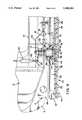
- FIG. 2is a front sectional view with portions cut away of the seat adjuster shown in FIG. 1.
- FIGS. 3 and 4are taken along lines 3--3 and 4--4 in FIG. 2, respectively.
- a preferred embodiment seat adjuster 7is provided.
- the fore and aft seat adjusteris oriented in a fore and aft direction and attached thereto is a multi-member seat frame member 10.
- Seat frame member 10has inner and outer walls 14 and 12 which support a seat bun 11 and also provide for pivotal connection of a seat back 9 in a conventional manner.
- the seat adjuster 7has a pair of channels 40. Each channel has an inner surface as defined by an upper concave surface 46 and a lower concave curvilinear surface 50, which are joined by a generally vertical inner surface 48.
- the channel 40is also provided with a lock bar 26 which is connected thereto by rivets 84.
- the lock plate or bar 26has a series of equally spaced apertures 28 to allow for insertion of a locking pin 24.
- the locking plate 26in alternative embodiments may be welded or affixed by a thread connector to the channel 40. Alternatively, the lock plate 26 may be eliminated altogether by placing the apertures 28 into the channel section 40, if so desired.
- the channel 40has a lower portion 86 with an aperture to allow it to be boltably attached to the vehicle floor panel 51.
- the vehicle floor panel 51is slightly submerged as compared with the remainder of the vehicle floor panel 57, thereby allowing the frame 10 of the vehicle seat to have as low a profile as possible.
- the forward vehicle wheel 42 and a rearward vehicle wheel 44Captured within the channel 40 and in rolling contact with the lower portion 50 of the channel is the forward vehicle wheel 42 and a rearward vehicle wheel 44. Both wheels are typically fabricated from a polymeric, preferably elastomeric, material and support the frame for movement fore and aft with respect to the vehicle floor. To prevent the rollers or wheels 42 and 44 from coming out of the channel, there are provided stops 66 (only the forward stop is shown) which effectively capture the wheels 42 and 44 within the channel 40.
- the wheelshave a cross-sectional profile generally aligned with the lower concave surface 50.
- the wheel 42is mounted by a tubular shaft provided by a housing member 20.
- Housing member 20is threadably connected with the frame wall 12 by virtue of a frame nut 15.
- a shoulder 88 in the housing membercaptures a bracket 22 to the frame wall 12 also.
- the housinghas surrounding it a cylindrical mounting member 56 which has a flared end 90 which mounts the wheel 42 on the tubular axle 20.
- the mounting member 56is held in place by a spring clip 58. Since the wheel is an elastomeric member, contact of the wheel with the bracket 22 which is typically metallic would cause an increase in friction. Therefore, there is a polymeric spacer 54 typically comprised of nylon, and mounting member 56 is allowed to rotate to minimize relative movement of the mounting member 56 with respect to the wheel 42 to prevent cutting the wheel 42.
- the housing member 20has inserted therein a locking pin 24.
- the locking pinis biased into engagement with one of the apertures 28 by a leaf spring 30.
- Leaf spring 30is riveted to the outer frame wall member 12.
- the leaf spring 30captures an end of the locking pin 24, pushing it outwardly, and also has an aperture for passage of a cable 62 which has a connecting bullet 64.
- the cable 62is guided by cable guide 60.
- the cable guide 60is connected with a pivotal latch 70.
- the brackethas an extension 78 which has at a top end a guide shoe 74, which is in continual contact with the upper concave surface 46 of the channel.
- the shoe 74also has a slot or hole 76 to allow it to be more compressible.
- the upper guide shoe 74is in continual contact; therefore, "chucking", which is vertical rocking of the seat, is eliminated since the guide 74 and the wheels 42 will always be in contact with their respective channel surfaces.
- the bracket 22is one continuous member connected with both housings and having only one centrally located shoe.
- the release latch 70In operation to allow adjustment of the seat, the release latch 70 is pulled upward by the vehicle seat occupant, which causes a tensional force to be exerted upon cable 62, pulling the locking pin 24 out of its engagement with the lock bar aperture 28. Release of the latch 70 will allow the pin 24 to re-engage with one of the apertures 28 to set the new position of the seat.
- Another advantage of the applicant's inventionis that the rear brackets 92 allow for direct attachment of the vehicle seat belt. Therefore, mounting of the vehicle seat belt to the floor of the vehicle is eliminated, and readjustment of the seat belt due to adjustment in the seat can be eliminated or reduced.
Landscapes
- Engineering & Computer Science (AREA)
- Aviation & Aerospace Engineering (AREA)
- Transportation (AREA)
- Mechanical Engineering (AREA)
- Seats For Vehicles (AREA)
Abstract
Description
Claims (10)
Priority Applications (1)
| Application Number | Priority Date | Filing Date | Title |
|---|---|---|---|
| US07/993,546US5348261A (en) | 1992-12-21 | 1992-12-21 | Low mass manual two-way seat adjuster |
Applications Claiming Priority (1)
| Application Number | Priority Date | Filing Date | Title |
|---|---|---|---|
| US07/993,546US5348261A (en) | 1992-12-21 | 1992-12-21 | Low mass manual two-way seat adjuster |
Publications (1)
| Publication Number | Publication Date |
|---|---|
| US5348261Atrue US5348261A (en) | 1994-09-20 |
Family
ID=25539669
Family Applications (1)
| Application Number | Title | Priority Date | Filing Date |
|---|---|---|---|
| US07/993,546Expired - LifetimeUS5348261A (en) | 1992-12-21 | 1992-12-21 | Low mass manual two-way seat adjuster |
Country Status (1)
| Country | Link |
|---|---|
| US (1) | US5348261A (en) |
Cited By (31)
| Publication number | Priority date | Publication date | Assignee | Title |
|---|---|---|---|---|
| US5730412A (en)* | 1996-02-09 | 1998-03-24 | Shrock Manufacturing, Inc. | Locking adjustable seat |
| EP0779174A3 (en)* | 1995-12-15 | 1998-09-02 | Johnson Controls/ Naue Engineering GmbH | Longitudinal adjustment of a seat |
| EP0765776A3 (en)* | 1995-09-29 | 1998-10-21 | Volkswagen Aktiengesellschaft | Roller guide for longitudinally adjustable seat and axle construction useful therefor |
| US5839773A (en)* | 1997-10-15 | 1998-11-24 | Lear Corporation | Rolling stowable seat |
| US5979964A (en)* | 1997-10-15 | 1999-11-09 | Lear Corporation | Double pivoting stowable seat |
| US6161756A (en)* | 1999-02-04 | 2000-12-19 | Upton; Robert D. | Adjustable mailbox extender |
| WO2000076802A1 (en)* | 1999-06-11 | 2000-12-21 | P.L. Porter Co. | System for coordinating opening and closing of multiple mechanical locks for a vehicle |
| US6176460B1 (en)* | 1997-12-25 | 2001-01-23 | Aisin Seiki Kabushiki Kaisha | Seat sliding apparatus for a vehicle |
| WO2001023207A1 (en)* | 1999-09-30 | 2001-04-05 | Fico Cables, Lda | Force transmission for releasing the locking catch of a folding backrest of a motor vehicle seat |
| US6264180B1 (en)* | 1999-05-27 | 2001-07-24 | Sears Manufacturing Co. | Axially adjustable roller assembly |
| DE10034008A1 (en)* | 2000-07-07 | 2002-01-17 | Volkswagen Ag | Seat position adjuster for vehicles |
| US6460818B1 (en)* | 2001-04-26 | 2002-10-08 | Garelick Mfg. Co. | Adjustable lockable tandem slide for boat seat |
| US20030013111A1 (en)* | 1999-05-21 | 2003-01-16 | Eric Henderson | Method and apparatus for solid state molecular analysis |
| DE10229385A1 (en)* | 2001-06-29 | 2003-01-30 | Volkswagen Ag | Device for a motor vehicle, airplane, train, and ship for adjusting and/or locking a component connected to a structure comprises an adjusting device and a clamping device arranged on an undercarriage of the component |
| US6585321B1 (en)* | 2000-11-28 | 2003-07-01 | Tachi-S Co., Ltd. | Seat adjuster for vehicle seat |
| DE102004007168A1 (en)* | 2004-02-09 | 2005-08-25 | Volkswagen Ag | Mechanism for removing load on rollers in systems for adjusting car seats comprises jaws in which roller is mounted with lower section fitting under lip on the floor rail which are locked in place by releasable wedge |
| ES2242476A1 (en)* | 2002-12-31 | 2005-11-01 | Antonio Oblanca Martinez | Chair or armchair with sliding seat, has seat sliding system consisting of rollers, bearings, or balls arranged in circulation guide rails and structured according to chair or armchair dimensions |
| US20070090663A1 (en)* | 2005-10-20 | 2007-04-26 | Ewers David J | Collapsible seat mechanism with integrated subfloor |
| CN100364807C (en)* | 2003-08-18 | 2008-01-30 | 本田技研工业株式会社 | Vehicle Seats and Vehicles |
| US7556233B2 (en)* | 2003-04-24 | 2009-07-07 | Sears Manufacturing Co. | Dual track seat adjustment apparatus |
| US8668180B2 (en) | 2011-07-13 | 2014-03-11 | Gifu Auto Body Co., Ltd. | Seat slide device |
| WO2014049651A1 (en)* | 2012-09-27 | 2014-04-03 | Gifu Auto Body Co., Ltd. | Seat slide device |
| US20170166091A1 (en)* | 2015-12-15 | 2017-06-15 | Lear Corporation | Track assembly |
| US9738180B2 (en)* | 2016-01-27 | 2017-08-22 | Brose Fahzeugteile GmbH & Co. KG, Coburg | Adjuster track assembly for a vehicle seat |
| DE102006051564B4 (en) | 2006-11-02 | 2018-12-13 | Volkswagen Ag | Sitzarretierungssysteme |
| US10286812B2 (en)* | 2016-05-03 | 2019-05-14 | Grammer Ag | Vehicle seat with a roller guide |
| US10308145B2 (en) | 2015-12-15 | 2019-06-04 | Lear Corporation | Track assembly |
| JP2020117137A (en)* | 2019-01-25 | 2020-08-06 | トヨタ紡織株式会社 | Slide device |
| US11584264B2 (en)* | 2018-10-09 | 2023-02-21 | Magna Seating Inc | Long rail assembly with side opening for vehicle seat adjustment |
| US20240101011A1 (en)* | 2022-09-26 | 2024-03-28 | Das Co., Ltd | Gap prevention structure of seat rail for vehicle |
| FR3143463A1 (en)* | 2022-12-20 | 2024-06-21 | Renault S.A.S | method of locking the position of a motor vehicle seat, system for locking a motor vehicle seat and motor vehicle equipped with such a system |
Citations (24)
| Publication number | Priority date | Publication date | Assignee | Title |
|---|---|---|---|---|
| US1735518A (en)* | 1927-01-03 | 1929-11-12 | Paralock Company | Vehicle seat |
| US1756230A (en)* | 1926-07-19 | 1930-04-29 | Paralock Company | Automobile seat |
| US2102979A (en)* | 1934-11-26 | 1937-12-21 | Harry M Smith | Motor vehicle safety seat |
| US2141093A (en)* | 1935-01-14 | 1938-12-20 | Henney Motor Co | Slidable seat |
| US2225074A (en)* | 1937-10-13 | 1940-12-17 | Wagner E R Mfg Co | Seat adjuster |
| US2239917A (en)* | 1939-06-22 | 1941-04-29 | Le Grand S Whedon | Adjustable vehicle seat support |
| US2264860A (en)* | 1939-04-07 | 1941-12-02 | American Forging & Socket Co | Adjustable support |
| US2396511A (en)* | 1943-01-18 | 1946-03-12 | Morris Motors Ltd | Vehicle seat mounting |
| GB637219A (en)* | 1948-04-23 | 1950-05-17 | Victor Ernest Freestone | Improvements in or relating to sliding or adjustable seats |
| US3022976A (en)* | 1960-09-06 | 1962-02-27 | Yee C Zia | Safety adjustable-seat mounting for front seat of a vehicle |
| US3100617A (en)* | 1960-07-22 | 1963-08-13 | Bostrom Mfg Company | Vehicle seat fore and aft shock isolator |
| US4157797A (en)* | 1977-11-17 | 1979-06-12 | Anthony Fox | Seating assembly for aircraft |
| US4209159A (en)* | 1977-01-22 | 1980-06-24 | C. Rob. Hammerstein Gmbh | Lockable guide assembly for adjustable vehicle seats |
| US4378927A (en)* | 1979-05-16 | 1983-04-05 | Uop Inc. | Vehicle seat mounting devices |
| US4432524A (en)* | 1981-07-29 | 1984-02-21 | General Motors Corporation | Three point seat adjuster |
| US4483504A (en)* | 1980-12-27 | 1984-11-20 | P. A. Rentrop Hubbert & Wagner Fahrzeugausstattunger Gmbh & Co. Kg | Slide rail assemblies |
| US4550933A (en)* | 1982-04-08 | 1985-11-05 | Ase (Uk) Limited | Adjustable anchorage |
| US4720072A (en)* | 1985-05-17 | 1988-01-19 | Toyota Jidosha Kabushiki Kaisha | Belt anchor incorporating seat track structure |
| DD255133A1 (en)* | 1986-12-19 | 1988-03-23 | Sachsenring Automobilwerke | LENGTH OF MOTOR VEHICLES |
| US4760988A (en)* | 1986-04-09 | 1988-08-02 | Cycles Peugeot | Slide structure for a motor vehicle seat structure |
| US4790597A (en)* | 1986-10-29 | 1988-12-13 | Firma C. Rob Hammerstein Gmbh | Vehicle seat with a longitudinal guide, with an adjustment of height or inclination, and with an attachment for seat belt lock |
| US4940285A (en)* | 1988-03-31 | 1990-07-10 | Aisin Seiki Kabushiki Kaisha | Seat sliding apparatus for vehicles |
| US4941636A (en)* | 1988-09-16 | 1990-07-17 | Ikeda Bussan Company Ltd. | Locking slide apparatus for mounting a seat |
| US5014960A (en)* | 1988-03-13 | 1991-05-14 | Tachi-S Co., Ltd. | Fore-and-aft suspension device for automotive seat |
- 1992
- 1992-12-21USUS07/993,546patent/US5348261A/ennot_activeExpired - Lifetime
Patent Citations (24)
| Publication number | Priority date | Publication date | Assignee | Title |
|---|---|---|---|---|
| US1756230A (en)* | 1926-07-19 | 1930-04-29 | Paralock Company | Automobile seat |
| US1735518A (en)* | 1927-01-03 | 1929-11-12 | Paralock Company | Vehicle seat |
| US2102979A (en)* | 1934-11-26 | 1937-12-21 | Harry M Smith | Motor vehicle safety seat |
| US2141093A (en)* | 1935-01-14 | 1938-12-20 | Henney Motor Co | Slidable seat |
| US2225074A (en)* | 1937-10-13 | 1940-12-17 | Wagner E R Mfg Co | Seat adjuster |
| US2264860A (en)* | 1939-04-07 | 1941-12-02 | American Forging & Socket Co | Adjustable support |
| US2239917A (en)* | 1939-06-22 | 1941-04-29 | Le Grand S Whedon | Adjustable vehicle seat support |
| US2396511A (en)* | 1943-01-18 | 1946-03-12 | Morris Motors Ltd | Vehicle seat mounting |
| GB637219A (en)* | 1948-04-23 | 1950-05-17 | Victor Ernest Freestone | Improvements in or relating to sliding or adjustable seats |
| US3100617A (en)* | 1960-07-22 | 1963-08-13 | Bostrom Mfg Company | Vehicle seat fore and aft shock isolator |
| US3022976A (en)* | 1960-09-06 | 1962-02-27 | Yee C Zia | Safety adjustable-seat mounting for front seat of a vehicle |
| US4209159A (en)* | 1977-01-22 | 1980-06-24 | C. Rob. Hammerstein Gmbh | Lockable guide assembly for adjustable vehicle seats |
| US4157797A (en)* | 1977-11-17 | 1979-06-12 | Anthony Fox | Seating assembly for aircraft |
| US4378927A (en)* | 1979-05-16 | 1983-04-05 | Uop Inc. | Vehicle seat mounting devices |
| US4483504A (en)* | 1980-12-27 | 1984-11-20 | P. A. Rentrop Hubbert & Wagner Fahrzeugausstattunger Gmbh & Co. Kg | Slide rail assemblies |
| US4432524A (en)* | 1981-07-29 | 1984-02-21 | General Motors Corporation | Three point seat adjuster |
| US4550933A (en)* | 1982-04-08 | 1985-11-05 | Ase (Uk) Limited | Adjustable anchorage |
| US4720072A (en)* | 1985-05-17 | 1988-01-19 | Toyota Jidosha Kabushiki Kaisha | Belt anchor incorporating seat track structure |
| US4760988A (en)* | 1986-04-09 | 1988-08-02 | Cycles Peugeot | Slide structure for a motor vehicle seat structure |
| US4790597A (en)* | 1986-10-29 | 1988-12-13 | Firma C. Rob Hammerstein Gmbh | Vehicle seat with a longitudinal guide, with an adjustment of height or inclination, and with an attachment for seat belt lock |
| DD255133A1 (en)* | 1986-12-19 | 1988-03-23 | Sachsenring Automobilwerke | LENGTH OF MOTOR VEHICLES |
| US5014960A (en)* | 1988-03-13 | 1991-05-14 | Tachi-S Co., Ltd. | Fore-and-aft suspension device for automotive seat |
| US4940285A (en)* | 1988-03-31 | 1990-07-10 | Aisin Seiki Kabushiki Kaisha | Seat sliding apparatus for vehicles |
| US4941636A (en)* | 1988-09-16 | 1990-07-17 | Ikeda Bussan Company Ltd. | Locking slide apparatus for mounting a seat |
Cited By (37)
| Publication number | Priority date | Publication date | Assignee | Title |
|---|---|---|---|---|
| EP0765776A3 (en)* | 1995-09-29 | 1998-10-21 | Volkswagen Aktiengesellschaft | Roller guide for longitudinally adjustable seat and axle construction useful therefor |
| EP0779174A3 (en)* | 1995-12-15 | 1998-09-02 | Johnson Controls/ Naue Engineering GmbH | Longitudinal adjustment of a seat |
| US5730412A (en)* | 1996-02-09 | 1998-03-24 | Shrock Manufacturing, Inc. | Locking adjustable seat |
| US5839773A (en)* | 1997-10-15 | 1998-11-24 | Lear Corporation | Rolling stowable seat |
| US5979964A (en)* | 1997-10-15 | 1999-11-09 | Lear Corporation | Double pivoting stowable seat |
| US6176460B1 (en)* | 1997-12-25 | 2001-01-23 | Aisin Seiki Kabushiki Kaisha | Seat sliding apparatus for a vehicle |
| US6161756A (en)* | 1999-02-04 | 2000-12-19 | Upton; Robert D. | Adjustable mailbox extender |
| US20030013111A1 (en)* | 1999-05-21 | 2003-01-16 | Eric Henderson | Method and apparatus for solid state molecular analysis |
| US6264180B1 (en)* | 1999-05-27 | 2001-07-24 | Sears Manufacturing Co. | Axially adjustable roller assembly |
| WO2000076802A1 (en)* | 1999-06-11 | 2000-12-21 | P.L. Porter Co. | System for coordinating opening and closing of multiple mechanical locks for a vehicle |
| WO2001023207A1 (en)* | 1999-09-30 | 2001-04-05 | Fico Cables, Lda | Force transmission for releasing the locking catch of a folding backrest of a motor vehicle seat |
| DE10034008A1 (en)* | 2000-07-07 | 2002-01-17 | Volkswagen Ag | Seat position adjuster for vehicles |
| DE10034008B4 (en)* | 2000-07-07 | 2012-04-19 | Volkswagen Ag | Device for adjusting and locking a longitudinally displaceable seat |
| US6585321B1 (en)* | 2000-11-28 | 2003-07-01 | Tachi-S Co., Ltd. | Seat adjuster for vehicle seat |
| US6460818B1 (en)* | 2001-04-26 | 2002-10-08 | Garelick Mfg. Co. | Adjustable lockable tandem slide for boat seat |
| DE10229385A1 (en)* | 2001-06-29 | 2003-01-30 | Volkswagen Ag | Device for a motor vehicle, airplane, train, and ship for adjusting and/or locking a component connected to a structure comprises an adjusting device and a clamping device arranged on an undercarriage of the component |
| DE10229385B4 (en)* | 2001-06-29 | 2016-09-01 | Volkswagen Ag | Device for fastening a restraint system of a means of transport or means of transport |
| ES2242476A1 (en)* | 2002-12-31 | 2005-11-01 | Antonio Oblanca Martinez | Chair or armchair with sliding seat, has seat sliding system consisting of rollers, bearings, or balls arranged in circulation guide rails and structured according to chair or armchair dimensions |
| ES2242476B1 (en)* | 2002-12-31 | 2006-12-01 | Antonio Oblanca Martinez | CHAIR OR ARMCHAIR WITH DISPLACABLE SEAT. |
| US7556233B2 (en)* | 2003-04-24 | 2009-07-07 | Sears Manufacturing Co. | Dual track seat adjustment apparatus |
| CN100364807C (en)* | 2003-08-18 | 2008-01-30 | 本田技研工业株式会社 | Vehicle Seats and Vehicles |
| DE102004007168A1 (en)* | 2004-02-09 | 2005-08-25 | Volkswagen Ag | Mechanism for removing load on rollers in systems for adjusting car seats comprises jaws in which roller is mounted with lower section fitting under lip on the floor rail which are locked in place by releasable wedge |
| DE102004007168B4 (en)* | 2004-02-09 | 2013-01-24 | Volkswagen Ag | Method for relieving rollers in guide rails |
| US20070090663A1 (en)* | 2005-10-20 | 2007-04-26 | Ewers David J | Collapsible seat mechanism with integrated subfloor |
| US7377571B2 (en) | 2005-10-20 | 2008-05-27 | Chrysler Llc | Collapsible seat mechanism with integrated subfloor |
| DE102006051564B4 (en) | 2006-11-02 | 2018-12-13 | Volkswagen Ag | Sitzarretierungssysteme |
| US8668180B2 (en) | 2011-07-13 | 2014-03-11 | Gifu Auto Body Co., Ltd. | Seat slide device |
| WO2014049651A1 (en)* | 2012-09-27 | 2014-04-03 | Gifu Auto Body Co., Ltd. | Seat slide device |
| US20170166091A1 (en)* | 2015-12-15 | 2017-06-15 | Lear Corporation | Track assembly |
| US9919624B2 (en)* | 2015-12-15 | 2018-03-20 | Lear Corporation | Track assembly |
| US10308145B2 (en) | 2015-12-15 | 2019-06-04 | Lear Corporation | Track assembly |
| US9738180B2 (en)* | 2016-01-27 | 2017-08-22 | Brose Fahzeugteile GmbH & Co. KG, Coburg | Adjuster track assembly for a vehicle seat |
| US10286812B2 (en)* | 2016-05-03 | 2019-05-14 | Grammer Ag | Vehicle seat with a roller guide |
| US11584264B2 (en)* | 2018-10-09 | 2023-02-21 | Magna Seating Inc | Long rail assembly with side opening for vehicle seat adjustment |
| JP2020117137A (en)* | 2019-01-25 | 2020-08-06 | トヨタ紡織株式会社 | Slide device |
| US20240101011A1 (en)* | 2022-09-26 | 2024-03-28 | Das Co., Ltd | Gap prevention structure of seat rail for vehicle |
| FR3143463A1 (en)* | 2022-12-20 | 2024-06-21 | Renault S.A.S | method of locking the position of a motor vehicle seat, system for locking a motor vehicle seat and motor vehicle equipped with such a system |
Similar Documents
| Publication | Publication Date | Title |
|---|---|---|
| US5348261A (en) | Low mass manual two-way seat adjuster | |
| US9919624B2 (en) | Track assembly | |
| US4640550A (en) | Adjustable fastening device | |
| US6637712B1 (en) | Automotive seat track lock mechanism with positive engagement | |
| US5447352A (en) | Seat slide mechanism for vehicles | |
| US7314204B2 (en) | Sliding rail system | |
| US5125611A (en) | Vehicle seat adjuster with crash bars | |
| US5286076A (en) | Seat slide device | |
| US7168671B2 (en) | Low profile seat suspension | |
| US7648115B2 (en) | Seat slide locator | |
| US6945505B2 (en) | Seat mount assemblies for tractors | |
| GB2107575A (en) | Vehicle seat slides | |
| US4500062A (en) | Adjustable seat leveling mechanism | |
| US20140339747A1 (en) | Fore-aft vibration isolator | |
| US3350046A (en) | Seat slide assembly for automotive vehicles | |
| US2278101A (en) | Sliding seat mounting for vehicles | |
| US20120205411A1 (en) | Adjustable accessory support assembly | |
| US3204916A (en) | Vehicle seaft track construction for use with seat belts | |
| US5425522A (en) | Vehicle seat adjuster with conveniently accessible rotary actuator | |
| EP1527943B1 (en) | Seat slide device for a vehicle | |
| US5641146A (en) | Seat sliding apparatus for a vehicle | |
| US7810779B2 (en) | Apparatus for preventing actuation of a vehicle seat position adjustment device | |
| US4817904A (en) | Seat position adjusting mechanism for a vehicle | |
| IE46660B1 (en) | Improvements in or relating to a slide for a vehicle seat,particularly for the seat of an automobile vehicle | |
| US4520982A (en) | Slide adjustment apparatus |
Legal Events
| Date | Code | Title | Description |
|---|---|---|---|
| AS | Assignment | Owner name:GENERAL MOTORS CORPORATION, MICHIGAN Free format text:ASSIGNMENT OF ASSIGNORS INTEREST.;ASSIGNOR:NINI, JAMES PETER;REEL/FRAME:006365/0797 Effective date:19921215 | |
| STCF | Information on status: patent grant | Free format text:PATENTED CASE | |
| FPAY | Fee payment | Year of fee payment:4 | |
| AS | Assignment | Owner name:LEAR CORPORATION, MICHIGAN Free format text:ASSIGNMENT OF ASSIGNORS INTEREST;ASSIGNOR:GENERAL MOTORS CORPORATION;REEL/FRAME:009453/0621 Effective date:19980831 | |
| FEPP | Fee payment procedure | Free format text:PAYOR NUMBER ASSIGNED (ORIGINAL EVENT CODE: ASPN); ENTITY STATUS OF PATENT OWNER: LARGE ENTITY | |
| FPAY | Fee payment | Year of fee payment:8 | |
| FPAY | Fee payment | Year of fee payment:12 | |
| AS | Assignment | Owner name:JPMORGAN CHASE BANK, N.A., AS GENERAL ADMINISTRATI Free format text:SECURITY AGREEMENT;ASSIGNOR:LEAR CORPORATION;REEL/FRAME:017858/0719 Effective date:20060425 | |
| AS | Assignment | Owner name:JPMORGAN CHASE BANK, N.A., AS ADMINISTRATIVE AGENT Free format text:GRANT OF FIRST LIEN SECURITY INTEREST IN PATENT RIGHTS;ASSIGNOR:LEAR CORPORATION;REEL/FRAME:023519/0267 Effective date:20091109 Owner name:JPMORGAN CHASE BANK, N.A., AS ADMINISTRATIVE AGENT Free format text:GRANT OF SECOND LIEN SECURITY INTEREST IN PATENT RIGHTS;ASSIGNOR:LEAR CORPORATION;REEL/FRAME:023519/0626 Effective date:20091109 | |
| AS | Assignment | Owner name:LEAR CORPORATION, MICHIGAN Free format text:RELEASE BY SECURED PARTY;ASSIGNOR:JPMORGAN CHASE BANK, N.A.;REEL/FRAME:032722/0553 Effective date:20100830 | |
| AS | Assignment | Owner name:LEAR CORPORATION, MICHIGAN Free format text:RELEASE BY SECURED PARTY;ASSIGNOR:JPMORGAN CHASE BANK, N.A.;REEL/FRAME:032770/0843 Effective date:20100830 | |
| AS | Assignment | Owner name:LEAR CORPORATION, MICHIGAN Free format text:RELEASE BY SECURED PARTY;ASSIGNOR:JPMORGAN CHASE BANK, N.A., AS AGENT;REEL/FRAME:037701/0340 Effective date:20160104 Owner name:LEAR CORPORATION, MICHIGAN Free format text:RELEASE BY SECURED PARTY;ASSIGNOR:JPMORGAN CHASE BANK, N.A., AS AGENT;REEL/FRAME:037701/0180 Effective date:20160104 Owner name:LEAR CORPORATION, MICHIGAN Free format text:RELEASE BY SECURED PARTY;ASSIGNOR:JPMORGAN CHASE BANK, N.A., AS AGENT;REEL/FRAME:037701/0251 Effective date:20160104 | |
| AS | Assignment | Owner name:LEAR CORPORATION, MICHIGAN Free format text:RELEASE BY SECURED PARTY;ASSIGNOR:JPMORGAN CHASE BANK, N.A., AS AGENT;REEL/FRAME:037731/0918 Effective date:20160104 |