US5348005A - Simulation for pulse oximeter - Google Patents
Simulation for pulse oximeterDownload PDFInfo
- Publication number
- US5348005A US5348005AUS08/057,752US5775293AUS5348005AUS 5348005 AUS5348005 AUS 5348005AUS 5775293 AUS5775293 AUS 5775293AUS 5348005 AUS5348005 AUS 5348005A
- Authority
- US
- United States
- Prior art keywords
- pulse oximeter
- light flashes
- electrical signal
- light
- red
- Prior art date
- Legal status (The legal status is an assumption and is not a legal conclusion. Google has not performed a legal analysis and makes no representation as to the accuracy of the status listed.)
- Ceased
Links
- 238000004088simulationMethods0.000titledescription6
- 238000000034methodMethods0.000claimsabstractdescription16
- 238000001514detection methodMethods0.000claimsabstractdescription5
- 230000000903blocking effectEffects0.000claims2
- 230000003321amplificationEffects0.000claims1
- 230000008878couplingEffects0.000claims1
- 238000010168coupling processMethods0.000claims1
- 238000005859coupling reactionMethods0.000claims1
- 238000003199nucleic acid amplification methodMethods0.000claims1
- 238000012360testing methodMethods0.000description21
- 239000008280bloodSubstances0.000description14
- 210000004369bloodAnatomy0.000description14
- 230000036772blood pressureEffects0.000description8
- QVGXLLKOCUKJST-UHFFFAOYSA-Natomic oxygenChemical compound[O]QVGXLLKOCUKJST-UHFFFAOYSA-N0.000description7
- 229910052760oxygenInorganic materials0.000description7
- 239000001301oxygenSubstances0.000description7
- 238000005259measurementMethods0.000description6
- 238000012544monitoring processMethods0.000description6
- 238000002106pulse oximetryMethods0.000description6
- 238000010586diagramMethods0.000description5
- 230000000541pulsatile effectEffects0.000description5
- 229910000831SteelInorganic materials0.000description4
- 238000002835absorbanceMethods0.000description4
- 230000004044responseEffects0.000description4
- 239000010959steelSubstances0.000description4
- 238000013459approachMethods0.000description3
- 230000009977dual effectEffects0.000description3
- 230000003287optical effectEffects0.000description3
- 238000012163sequencing techniqueMethods0.000description3
- INGWEZCOABYORO-UHFFFAOYSA-N2-(furan-2-yl)-7-methyl-1h-1,8-naphthyridin-4-oneChemical compoundN=1C2=NC(C)=CC=C2C(O)=CC=1C1=CC=CO1INGWEZCOABYORO-UHFFFAOYSA-N0.000description2
- 238000012935AveragingMethods0.000description2
- 230000002238attenuated effectEffects0.000description2
- 230000005540biological transmissionEffects0.000description2
- 239000000872bufferSubstances0.000description2
- 230000031700light absorptionEffects0.000description2
- 238000010606normalizationMethods0.000description2
- 206010002091AnaesthesiaDiseases0.000description1
- 108010054147HemoglobinsProteins0.000description1
- 102000001554HemoglobinsHuman genes0.000description1
- 206010021143HypoxiaDiseases0.000description1
- 108010064719OxyhemoglobinsProteins0.000description1
- 241000098700Sarcocheilichthys parvusSpecies0.000description1
- 238000010521absorption reactionMethods0.000description1
- 230000037005anaesthesiaEffects0.000description1
- 230000008901benefitEffects0.000description1
- 230000008859changeEffects0.000description1
- 238000010276constructionMethods0.000description1
- 230000001276controlling effectEffects0.000description1
- 229940124446critical care medicineDrugs0.000description1
- 108010002255deoxyhemoglobinProteins0.000description1
- 230000036541healthEffects0.000description1
- 230000010247heart contractionEffects0.000description1
- 208000018875hypoxemiaDiseases0.000description1
- 238000000338in vitroMethods0.000description1
- 230000003278mimic effectEffects0.000description1
- 239000000203mixtureSubstances0.000description1
- 238000012986modificationMethods0.000description1
- 230000004048modificationEffects0.000description1
- 238000002640oxygen therapyMethods0.000description1
- 238000006213oxygenation reactionMethods0.000description1
- 230000008569processEffects0.000description1
- 238000012545processingMethods0.000description1
- 230000001105regulatory effectEffects0.000description1
- 239000000523sampleSubstances0.000description1
- 238000012216screeningMethods0.000description1
- 230000035945sensitivityEffects0.000description1
- 238000001356surgical procedureMethods0.000description1
- 230000002747voluntary effectEffects0.000description1
Images


Classifications
- A—HUMAN NECESSITIES
- A61—MEDICAL OR VETERINARY SCIENCE; HYGIENE
- A61B—DIAGNOSIS; SURGERY; IDENTIFICATION
- A61B5/00—Measuring for diagnostic purposes; Identification of persons
- A61B5/145—Measuring characteristics of blood in vivo, e.g. gas concentration or pH-value ; Measuring characteristics of body fluids or tissues, e.g. interstitial fluid or cerebral tissue
- A61B5/1495—Calibrating or testing of in-vivo probes
- A—HUMAN NECESSITIES
- A61—MEDICAL OR VETERINARY SCIENCE; HYGIENE
- A61B—DIAGNOSIS; SURGERY; IDENTIFICATION
- A61B2560/00—Constructional details of operational features of apparatus; Accessories for medical measuring apparatus
- A61B2560/02—Operational features
- A61B2560/0223—Operational features of calibration, e.g. protocols for calibrating sensors
- A61B2560/0228—Operational features of calibration, e.g. protocols for calibrating sensors using calibration standards
- A61B2560/0233—Optical standards
Definitions
- the present inventiongenerally relates to the field of pulse oximeters, and more particularly, relates to a device and method for testing or calibrating pulse oximeters.
- the non-invasive monitoring of arterial oxygen saturation (SaO 2 ) by pulse oximetryis used in many clinical applications.
- SaO 2 monitoringis performed during surgery, in critical care situations, for hypoxemia screening, in the emergency room, and in the field.
- the instrumentsare small and lightweight, making them ideal for neonatal, pediatric and ambulatory applications. Because this instrument is capable of providing continuous and safe measurements of blood oxygenation non-invasively, the pulse oximeter is widely recognized as one of the most important technological advances in bedside monitoring.
- the American Society of Anesthesiologistsrecommended pulse oximetry as a standard of care for basic intraoperative monitoring, and in 1988, the Society for Critical Care Medicine recommended that this method be used for monitoring patients undergoing oxygen therapy.
- the mandatory or voluntary use of pulse oximetry by regulatory agencies and professional organizationsis likely to continue.
- pulse oximetersare small, easy-to-use and readily available, they have become widespread in the last decade.
- the high costs associated with health caremake the use of non-invasive pulse oximetry very attractive as it permits effective oxygen monitoring without the expensive clinical laboratory analysis of blood samples.
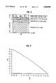
- Oxygen saturation measurementsrely on the difference in optical absorbance of deoxyhemoglobin (Hb) and oxyhemoglobin (HbO 2 ), as shown in FIG. 1.
- HbO 2absorbs less light in the red region (ca. 660 nm) than does Hb, but absorbs more strongly in the infrared region (ca. 940 nm). If both wavelengths of light are used, their opposite change in light absorbed as HbO 2 varies versus Hb produces a sensitive index of blood oxygen saturation.
- the "functional hemoglobin saturation"is defined as:
- Pulse oximetersthus employ two discrete wavelengths of light, which are passed through a given tissue (typically a finger). The amount of transmitted light for each wavelength is detected and subtracted from the incident light to determine the amount absorbed. From the ratio (R/IR or "red/infrared") of the amount of light absorbed at each wavelength, the blood oxygen saturation is calculated from a predetermined algorithm. If these were the only conditions of the measurement, the calculated saturation value would in some degree reflect the mixture of arterial and venous blood flowing through the tissue. However, in pulse oximetry the time-variant photoplethysmographic signal, caused by increases in arterial blood volume due to cardiac contraction, is used to determine the arterial blood oxygen saturation (FIG. 2). The advantage of this method is that the oxygen saturation values of the relatively constant flow of arterial and venous blood, as well as the constant absorption of light by the tissue, are discarded.
- the SaO 2 valuesare derived by analyzing only the changes in absorbance caused by the pulsating arterial blood at a red wavelength (e.g., 660 nm), where the absorbance of HbO 2 is less than that of Hb, and a second reference infrared wavelength (e.g., 940 nm), where the absorbance of HbO 2 is slightly larger than Hb.
- a red wavelengthe.g., 660 nm
- a second reference infrared wavelengthe.g. 940 nm
- This normalizationinvolves dividing the pulsatile (AC) component of the red and infrared photoplethysmograms (which is a result of the expansion and relaxation of the arterial blood) by the corresponding non-pulsatile (DC) component of the photoplethysmogram (which is due to the absorption of light by tissue, non-pulsatile arterial blood, and venous blood).
- This scaling processresults in a normalized red/infrared ratio (R/IR) which is virtually independent of the incident light intensity.
- R/IRcan thus be expressed as:
- Pulse oximetersare calibrated empirically by correlating the measured ratio of normalized AC/DC signals from the red and infrared photoplethysmograms with blood SaO 2 values obtained from a standard in vitro oximeter.
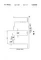
- a typical relationship between the normalized R/IR ratio and SaO 2is shown in FIG. 3.
- the amount of light absorbed by Hb and HbO 2is nearly the same, so the normalized amplitudes of the red and infrared signals are equal, and R/IR is 1.
- further calibrationshould not be required in the field because the optical properties of blood are fairly similar among different individuals.
- Pulse oximeter probesconsist of LEDs for two separate and discrete wavelengths (e.g., 660 and 940 nm) and a photodiode light detector. Three different light levels are measured by the photodiode: the red (660 nm) light level, the infrared (940 nm) light level, and the ambient light level. These three light sources are detected separately by a single photodiode by sequencing the red and infrared light sources on and off, allowing an interval when both are off in order to detect (and subtract out) ambient light.
- An example from the commercially available Ohmeda model 3700 pulse oximeteris shown in FIG. 4.
- Sequencing the red and infrared LEDs at a frequency that is an integer multiple of the power line frequencyallows the system to operate synchronously with flickering room lights. For example, fluorescent lights generate a 120 Hz flicker on 60 Hz power.
- the sequencingavoids potential interference of light flickers on the photodiode that would distort or disguise the tiny pulse signals of arterial pulse flow.
- the light timing sequence shown in FIG. 4cycles 480 times per second at 60 Hz power; 16 of the red-infrared-off sequences are used to calculate SaO 2 every 0.033 second. These signals are used differently by different pulse oximeter manufacturers, as described below.
- the response time of the instrumentdepends on the number of data points averaged before a final SaO 2 reading is displayed.
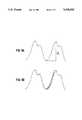
- There are two basic approaches to this averagingone of which relies on the time average of the peak-to-peak amplitudes of each pulse (FIG. 5A). This method depends on the patient's heart rate and is relatively slow as the signals are available for averaging only once every heartbeat.
- Another approachis to average a large number of step changes along the steep slopes of the photoplethysmogram (FIG. 5B). In this case, the response time in the instrument is shorter because there are many more data points between successive heartbeats; also, the accuracy and stability of the measured SaO 2 values are usually improved by this approach.
- pulse oximetersoffer other display features in addition to SaO 2 , such as the pulse rate and displays to indicate the pulse waveform and relative pulse amplitude. These help the user to partially assess the quality and reliability of the measurement. For instance, if the patient's actual heart rate does not agree with that displayed by the pulse oximeter, the displayed SaO 2 value is brought into question. In addition, the shape and stability of the photoplethysmographic waveform often serves as an indication of possible motion artifacts.
- pulse oximetersoffer such advantageous features as described above, are now mandatory for all anesthesias and tens of thousand's of oximeters are in clinical use, doctors and hospitals have no way of knowing if the oximeters are working correctly.
- Manufacturerssometimes provide simple electronic simulators to test the electronic circuitry of their oximeters, but these do not test the performance of the optical sensor and therefore are inadequate.
- U.S. Pat. Nos. 4,968,137 and 5,166,517are examples of prior art methods and devices for testing pulse oximeters.
- FIGS. 1-3are graphs for explaining the principles of pulse oximetry.
- FIG. 4is a graph for explaining the output of a photodetector on a known pulse oximeter.
- FIGS. 5A and 5Bare graphs for explaining response times of pulse oximeter instrumentation.
- FIGS. 6A-6Care schematic diagram of an oximeter test instrument according to an embodiment of the invention.
- FIG. 7is a circuit diagram of an oximeter test instrument according to an embodiment of the invention.
- FIG. 8is a circuit diagram showing elements of the circuit of FIG. 7 in greater detail.
- FIG. 6is a schematic diagram of a pulse oximeter detector or test instrument according to an embodiment of the invention.
- the test instrument shown in FIG. 6is intended for use with pulse oximeters employing sensors which clamp around the patient's finger.
- the test instrumenthas a finger-like shape which is intended to mimic that of the patient.
- the test fingermay be, for example, 3.5" long with a 0.75" diameter.
- the test instrumentis fabricated from steel.
- two long sensing photodiodesare positioned in the lower longitudinal slot 1, one diode having an infrared band pass filter so as to only receive IR, and a red LED light bar is placed in the upper longitudinal slot 2, with another photodiode placed so as to partially cover the light bar.
- the long, narrow shape of the test instrument (and the LED light bar)is intended to facilitate positioning of the instrument within the grip of the pulse oximeter, or the "unit-under-test" (UUT).
- the flat section at the end of the "finger”provides a mechanical connection point for an analog processing circuit board.
- the use of a steel constructionprovides both opacity between the UUT light source and the UUT detector, and electrical shielding between the pulsing calibrator LED and the sensitive calibrator photodiode. It has been found that such shielding is essential to provide accurate measurements of the UUT.
- the round smooth sideswill form a reasonably good seal with the UUT finger grip (e.g., Nellcor).
- the steel finger-shaped test instrument according to this embodimentis attached directly to the circuit board, it can be mounted at the end of a cable, much like a mouse. The electronics could then be placed within a computer, with, for example, only an photosensor preamplifier inside the "finger".
- the steel finger-shaped test instrumentis replaced with a printed circuit board cut to approximate finger width and length, with the two sensing photodiodes on the bottom surface and the LED bar with its associated photodiode mounted on the top surface. It should be noted that with a PC board it is still essential to provide opacity between the UUT light source and the UUT detector.
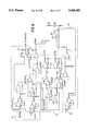
- FIG. 7is a circuit diagram of the oximeter test instrument according to an embodiment of the invention.
- the circuitryincludes a pair of photodiodes represented by the reference numeral 10 which feed a pulse separator and edge timing circuit 12, a pair of DC multipliers M1A, M1B which are coupled to the pulse separator and edge timing circuit 12 via a pair of switches S1A and S1B, respectively, a pair of AC multipliers M2A and M2B which are connected to receive the outputs of DC multipliers M1A and M1B, respectively, a multiplier M3A which is coupled to receive one of the outputs of AC multipliers M2A and M2B depending on the position of switch S2B, and a switch S2A which is coupled to selectively pass one of the outputs of DC multipliers M1A and M1B.
- switches S1A and S1Bare user controlled, whereas switches S2A and S2B are controlled according to an output of pulse separator and edge timing circuit 12. As will be discussed in greater detail below, switches S2A and S2B are controlled in accordance with detected IR flashes.
- the circuitry shown in FIG. 7further includes an amplifier A2 having an inverting terminal (-) which receives the signal passed by switch S2A, an amplifier A3 having an inverting terminal coupled to receive the output of amplifier A2 summed with the output of multiplier M3A, a servo amplifier A4 having a non-inverting terminal (+) coupled to receive the output of amplifier A3 and coupled to the drain of FET Q1 which has its source connected to ground and its gate coupled to receive an output of pulse separator and edge timing circuit 12, and an inverting terminal of amplifier A4 is coupled to receive an output of a pulse amplifier with baseline restore circuit 14.
- the circuit 14is coupled to a photodiode 18 which detects light emitted from LED bar 16.
- the ambient light simulation circuit 19includes a multiplier M3B which attenuates a DC reference signal under control of computer 20, an amplifier A5 having its non-inverting terminal connected to receive an output of multiplier M3B, and a driving transistor Q3 coupled between the LED BAR 16 and the output of amplifier A5.
- the circuitry of FIG. 7uses one photodetector to capture the red and infrared pulses from the UUT, and another photodetector which is filtered such that it captures IR only, and uses the timing of these pulses to generate modulated light pulses to the UUT (i.e., pulse oximeter) via an LED bar.
- the pulse separator and edge timing circuit 12receives the outputs of the photodiodes 10, and in response thereto outputs four signals.
- a first signal IR Switch(represented by dotted lines) is a switch control signal for IR. This signal controls switches S2A and S2B, and is used to select the AC and DC corresponding to the infrared transmission pulse wave. That is, when the pulse separator and edge timing signal receives an IR, this signal is supplied to switches S2A and S2B to select the AC and DC corresponding to the infrared transmission pulse wave. At all other times, the red values are selected so switches S2A and S2B are in the positions shown in FIG. 7.
- a second signal output by circuit 12is the red plus infrared (R+IR) pulses.
- this signalis supplied to the gate of FET Q1.
- a third signal provided by circuit 12is an electrical analog to the UUT red flash; this signal is provided to multiplier M1A via switch S1A.
- the fourth signal provided by circuit 12is an electrical analog to the UUT infrared flash; this signal is supplied to multiplier M1B via switch S1B.
- the circuit shown in FIG. 7includes three multiplier chips M1A and M1B, M2A and M2B, and M3A and M3B. Each of these chips contains dual multiplying digital-to-analog converters (DACs) with internal output amplifiers. This eliminates the amplifiers and their associated components from the circuit board, and brings them within desired multiplier accuracy specifications.
- DACsdigital-to-analog converters
- the multipliersmultiply by a computer-set value between 0 and -1; that is, the multipliers are both attenuating and inverting.
- Dual 12-bit multipliersare used for setting the finger density (DC attenuation) and creating the blood pressure wave form (AC attenuation); multipliers M1A, M1B and M2A, M2B, respectively.
- a single dual 8 bit multiplieris used to attenuate the AC wave (multiplier M3A) and control simulated ambient light (multiplier M3B).
- the switches S1A, S1Ballow selection between the analogs of the UUT flashes (i.e., IR or R) and a fixed voltage (e.g., -5 V) as the DC references.
- switches S1A, S1BWhen receiving the UUT light analogs, switches S1A, S1B are in the position shown in FIG. 7, and the multipliers M1A and M1B receive the R and IR analogs, respectively. However, the user is able to set switches S1A and S1B such that each of multipliers M1A and M1B receives the references signal (e.g., -5 V). This will cause the DC components of the R/IR equation (2) to drop out, thereby simplifying the equation for diagnostic purposes.
- the circuitrycan be designed such that the selection of the UUT light analogs by switches S1A and S1B is the default choice.
- the attenuated DC reference voltage(i.e., the output of multipliers M1A and M1B) becomes the reference for multipliers M2A and M2B. Further, the attenuated DC reference voltage is inverted by amplifier A2 into the range of 0 to -5 volts.
- the multipliers M2A and M2Bserve to create the R and IR waveforms.
- the IR waveformhas a peak multiplier setting of 1000, and the R waveform has a peak multiplier setting which varies from 400 to 3500.
- Multiplier M3Areceives the output of either AC multiplier, depending on the position of switch S2B, and attenuate the output passing through switch S2B from its maximum value down to zero. This attenuation simulates the strength of the blood pressure wave. For example, the value zero would correspond to no heart beat. This attenuation is also for the UUT pulse loss detection test and should allow demonstration of the UUT output invariance from the highest to the lowest non-alarm AC/DC ratio.
- the first element of the output stage of the circuitis amplifier A2, which inverts the positive DC levels out of multiplier M1.
- the inverted DCwhich is now negative, is then summed with the positive AC from multiplier M3A.
- the DCis a negative voltage which will be proportional to base brightness, and the AC is a positive voltage representing attenuation of the blood pressure wave.
- the R1/R2 resistor ratio at the input of amplifier A3sets the maximum AC at 25% of the DC applied to this summing and inverting stage. The actual AC is always less than this maximum, as the largest AC signal is only 3500/4096 times the DC out of multiplier M1A.
- the inverted and summed AC and DC from amplifier A3are applied to amplifier A4 through resistor R3 and are chopped by Q1.
- Q1is switched by the UUT R+IR light pulse; during the pulse, Q1 is off and amplifier A4 is driven by amplifier A3.
- the LED current(brightness) is commanded to be zero.
- Amplifier A4sets the brightness for the LED bar 16 to be proportional to the input voltage of amplifier A4 when Q1 is turned off.
- the LED bar 16is coupled to photodiode 18 which detects the light generated and feeds it back to amplifier A4. This is done to ensure that the LED bar output is linear.
- the test instrumentcontrols the light output directly, rather than depending on the linearity and temperature stability of the LED vs. the LED current.
- the ambient light simulation circuit 19includes a multiplier M3B, an amplifier A5 and a driving transistor Q2 and serves to generate a fixed current to the LED bar in addition to the red and infrared pulses in order to simulate ambient light.
- the multipliers M1A, M1B, M2A, M2B, M3A and M3Bare controlled by computer 20. This can be done using a simple program for setting the fixed parameters and then manipulating the R/IR ratio. The various control parameters for the multipliers are described below.
- the circuitincludes the multipliers M1A and M1B which cover the range from opaque to transparent, and is settable by the computer 20 over this range in 4,096 steps. Also, computer 20 is able to set the red and infrared DC attenuation (i.e., multipliers M1A and M1B) separately.
- the circuitincludes the multipliers M2A and M2B. As indicated above, these multipliers create the R and IR waveforms, with the IR waveform having a peak multiplier setting of 1000, and the R waveform having a peak multiplier setting which varies from 400 to 3500.
- the red to infrared ratio (R/IR) ratiocan range from 0.4 to 3.4, corresponding to 100% and 0% SaO 2 , respectively.
- Pulse oximetershave approximately 1% resolution; in order to effectively calibrate such an instrument, the calibrator should be several times better, preferably an order of magnitude. Therefore, the circuit employs a 12-bit multiplying digital-to-analog converter (DAC), which will provide 0.1% (or better) resolution of the full wave amplitude over the range of R/IR values from 0.4 to 3.5.
- the tracking accuracy between the two sections of the DAC chipis one bit or better.
- the AC to DC ratiocorresponds to the strength of the blood pressure wave, and this ratio is simulated by multiplier M3A.
- multiplier M3AOne of the tasks of a pulse oximeter is to sound an alarm if the blood pressure wave is lost. Therefore, an important question is: "At what level of wave weakness is the alarm tripped?"
- the computer 20is able to set the wave amplitude (i.e., multiplier M3A) from zero up to approximately 20% of the DC level in 256 steps.
- a blood pressure wave corresponding to one heartbeatis generated by the computer 20 feeding the AC multipliers M2A, M2B a series of 64 numbers corresponding to blood pressure amplitude, starting at zero and returning to zero. The series of 64 numbers then repeats to form the next beat. The 64 numbers are selected such that if the series of numbers were plotted against time, then the resulting curve would be a blood pressure wave corresponding to one heart beat.
- a simulated heart rateis established by the computer 20 setting the time between the presentation of each of the 64 numbers. For example, if they are presented to the multipliers 1/64th of a second apart, the full wave takes one second to generate, corresponding to 60 beats/minute. The computer 20 can readily set the time between multiplier settings so that any reasonable simulated heart rate can be established. A simulated heart rate range of between 30 and 240 bpm should be adequate for most applications.
- the ambient light simulation circuit 19serves to drive the LED bar 16 in order to simulate ambient light.
- Computer 20controls multiplier M3B of circuit 19 so as to allow for a settable minimum dc current through the LED bar 16.
- FIG. 8shows the pulse separator and edge timing circuit 12 and the pulse amplifier with baseline restore circuit 14 of FIG. 7 in greater detail.
- the photodiodes 10include a first diode for receiving both R and IR, and a second diode which is filtered so as to receive only IR, and the outputs of the diodes are supplied to the pulse separator and edge timing circuit 12.
- circuit 12comprises several amplifiers, comparators and buffers which are connected as shown so as to output four different signals. Specifically, circuit 12 outputs a signal representing R+IR, a signal representing IR only, a signal representing R only and the IR switch control signal. As shown in FIG.
- the IR+R signalis supplied to the gate of chopping transistor Q1 which has its drain connected to the non-inverting terminal of servo amplifier A4 whose output drives the LED bar 16 via driving transistor Q2.
- the pulse amplifierreceives the output of photodiode 18 (which is disposed so as to sit on the LED BAR 16) and includes several amplifiers and buffers. As discussed above, the circuit 14 provides an output to the inverting terminal of servo amplifier A4, thereby providing closed loop control of the LED BAR 16.
- the device and method according to the present inventionis able to simulate a living tissue, such as a finger, thereby enabling testing of a pulse oximeter by comparing the parameters of the simulated living tissue with the parameters obtained from the pulse oximeter under test.
Landscapes
- Life Sciences & Earth Sciences (AREA)
- Health & Medical Sciences (AREA)
- Physics & Mathematics (AREA)
- Heart & Thoracic Surgery (AREA)
- Molecular Biology (AREA)
- Pathology (AREA)
- Engineering & Computer Science (AREA)
- Biomedical Technology (AREA)
- Optics & Photonics (AREA)
- Medical Informatics (AREA)
- Biophysics (AREA)
- Surgery (AREA)
- Animal Behavior & Ethology (AREA)
- General Health & Medical Sciences (AREA)
- Public Health (AREA)
- Veterinary Medicine (AREA)
- Measurement Of The Respiration, Hearing Ability, Form, And Blood Characteristics Of Living Organisms (AREA)
Abstract
Description
Functional SaO.sub.2 ={[HbO.sub.2 ]/[HbO.sub.2 +Hb]}×100% (1)R/IR=[AC.sub.red /DC.sub.red ]/[AC.sub.ir /DC.sub.ir ] (2)
Claims (8)
Priority Applications (5)
| Application Number | Priority Date | Filing Date | Title |
|---|---|---|---|
| US08/057,752US5348005A (en) | 1993-05-07 | 1993-05-07 | Simulation for pulse oximeter |
| EP94916572AEP0648085B1 (en) | 1993-05-07 | 1994-05-02 | Simulation for pulse oximeter |
| DE69411841TDE69411841T2 (en) | 1993-05-07 | 1994-05-02 | SIMULATION FOR A PULSE OXIMETER |
| PCT/US1994/004544WO1994026161A1 (en) | 1993-05-07 | 1994-05-02 | Simulation for pulse oximeter |
| US10/852,774USRE39268E1 (en) | 1993-05-07 | 2004-05-25 | Simulation for pulse oximeter |
Applications Claiming Priority (1)
| Application Number | Priority Date | Filing Date | Title |
|---|---|---|---|
| US08/057,752US5348005A (en) | 1993-05-07 | 1993-05-07 | Simulation for pulse oximeter |
Related Child Applications (1)
| Application Number | Title | Priority Date | Filing Date |
|---|---|---|---|
| US10/852,774ReissueUSRE39268E1 (en) | 1993-05-07 | 2004-05-25 | Simulation for pulse oximeter |
Publications (1)
| Publication Number | Publication Date |
|---|---|
| US5348005Atrue US5348005A (en) | 1994-09-20 |
Family
ID=22012546
Family Applications (2)
| Application Number | Title | Priority Date | Filing Date |
|---|---|---|---|
| US08/057,752CeasedUS5348005A (en) | 1993-05-07 | 1993-05-07 | Simulation for pulse oximeter |
| US10/852,774Expired - LifetimeUSRE39268E1 (en) | 1993-05-07 | 2004-05-25 | Simulation for pulse oximeter |
Family Applications After (1)
| Application Number | Title | Priority Date | Filing Date |
|---|---|---|---|
| US10/852,774Expired - LifetimeUSRE39268E1 (en) | 1993-05-07 | 2004-05-25 | Simulation for pulse oximeter |
Country Status (4)
| Country | Link |
|---|---|
| US (2) | US5348005A (en) |
| EP (1) | EP0648085B1 (en) |
| DE (1) | DE69411841T2 (en) |
| WO (1) | WO1994026161A1 (en) |
Cited By (52)
| Publication number | Priority date | Publication date | Assignee | Title |
|---|---|---|---|---|
| US5784151A (en)* | 1996-12-03 | 1998-07-21 | Datrend Systems Inc. | Apparatus for testing a pulsed light oximeter |
| US5783821A (en)* | 1995-11-02 | 1998-07-21 | Costello, Jr.; Leo F. | Pulse oximeter testing |
| WO1999012008A1 (en)* | 1997-09-04 | 1999-03-11 | Avocet Medical, Inc. | Verification device for optical clinical assay systems |
| US6141572A (en)* | 1999-02-18 | 2000-10-31 | Bio-Tek Instruments, Inc. | Process and system for simultaneously simulating arterial and non-arterial blood oxygen values for pulse oximetry |
| US6400973B1 (en)* | 1998-01-20 | 2002-06-04 | Bowden's Automated Products, Inc. | Arterial blood flow simulator |
| US20030114737A1 (en)* | 2001-11-20 | 2003-06-19 | Minolta Co., Ltd. | Blood component measurement apparatus |
| US20060030763A1 (en)* | 2000-04-17 | 2006-02-09 | Nellcor Puritan Bennett Incorporated | Pulse oximeter sensor with piece-wise function |
| US7110570B1 (en)* | 2000-07-21 | 2006-09-19 | Trw Inc. | Application of human facial features recognition to automobile security and convenience |
| US20060247507A1 (en)* | 2005-05-02 | 2006-11-02 | Ruiter Karl A | Light transmission simulator for pulse oximeter |
| US20070172392A1 (en)* | 2005-12-13 | 2007-07-26 | Sen Chandan K | Apparatus, system and method for tissue oximetry |
| US20080077022A1 (en)* | 2006-09-27 | 2008-03-27 | Nellcor Puritan Bennett Incorporated | Method and apparatus for detection of venous pulsation |
| US20080221417A1 (en)* | 2007-03-09 | 2008-09-11 | Nellcor Puritan Bennett Llc | System and method for detection of venous pulsation |
| US7477924B2 (en) | 2006-05-02 | 2009-01-13 | Nellcor Puritan Bennett Llc | Medical sensor and technique for using the same |
| US7483731B2 (en) | 2005-09-30 | 2009-01-27 | Nellcor Puritan Bennett Llc | Medical sensor and technique for using the same |
| US7499740B2 (en) | 2004-02-25 | 2009-03-03 | Nellcor Puritan Bennett Llc | Techniques for detecting heart pulses and reducing power consumption in sensors |
| US7522948B2 (en) | 2006-05-02 | 2009-04-21 | Nellcor Puritan Bennett Llc | Medical sensor and technique for using the same |
| US20090112073A1 (en)* | 1999-03-25 | 2009-04-30 | Diab Mohamed K | Pulse oximeter probe-off detector |
| US20090287069A1 (en)* | 2007-11-25 | 2009-11-19 | Ic Therapeutics | Methods and apparatus for repeated ischemic conditioning treatment of hypertension and other medical conditions |
| US7650177B2 (en) | 2005-09-29 | 2010-01-19 | Nellcor Puritan Bennett Llc | Medical sensor for reducing motion artifacts and technique for using the same |
| US7676253B2 (en) | 2005-09-29 | 2010-03-09 | Nellcor Puritan Bennett Llc | Medical sensor and technique for using the same |
| RU2386388C1 (en)* | 2008-07-15 | 2010-04-20 | Федеральное государственное унитарное предприятие "ВСЕРОССИЙСКИЙ НАУЧНО-ИССЛЕДОВАТЕЛЬСКИЙ ИНСТИТУТ ОПТИКО-ФИЗИЧЕСКИХ ИЗМЕРЕНИЙ" (ФГУП "ВНИИОФИ") | Pulse oximeter tester |
| US20100179391A1 (en)* | 2009-01-15 | 2010-07-15 | Lifesync Corporation | Systems and methods for a wireless sensor proxy with feedback control |
| US7869849B2 (en) | 2006-09-26 | 2011-01-11 | Nellcor Puritan Bennett Llc | Opaque, electrically nonconductive region on a medical sensor |
| US7881762B2 (en) | 2005-09-30 | 2011-02-01 | Nellcor Puritan Bennett Llc | Clip-style medical sensor and technique for using the same |
| US7894869B2 (en) | 2007-03-09 | 2011-02-22 | Nellcor Puritan Bennett Llc | Multiple configuration medical sensor and technique for using the same |
| US7899510B2 (en) | 2005-09-29 | 2011-03-01 | Nellcor Puritan Bennett Llc | Medical sensor and technique for using the same |
| US8073518B2 (en) | 2006-05-02 | 2011-12-06 | Nellcor Puritan Bennett Llc | Clip-style medical sensor and technique for using the same |
| US8109882B2 (en) | 2007-03-09 | 2012-02-07 | Nellcor Puritan Bennett Llc | System and method for venous pulsation detection using near infrared wavelengths |
| US8145288B2 (en) | 2006-08-22 | 2012-03-27 | Nellcor Puritan Bennett Llc | Medical sensor for reducing signal artifacts and technique for using the same |
| CN102389314A (en)* | 2011-12-13 | 2012-03-28 | 秦皇岛市康泰医学系统有限公司 | Separation type pulse blood oxygen emulation system |
| US8175671B2 (en) | 2006-09-22 | 2012-05-08 | Nellcor Puritan Bennett Llc | Medical sensor for reducing signal artifacts and technique for using the same |
| US8190224B2 (en) | 2006-09-22 | 2012-05-29 | Nellcor Puritan Bennett Llc | Medical sensor for reducing signal artifacts and technique for using the same |
| US8221326B2 (en) | 2007-03-09 | 2012-07-17 | Nellcor Puritan Bennett Llc | Detection of oximetry sensor sites based on waveform characteristics |
| US8224412B2 (en) | 2000-04-17 | 2012-07-17 | Nellcor Puritan Bennett Llc | Pulse oximeter sensor with piece-wise function |
| US8260391B2 (en) | 2005-09-12 | 2012-09-04 | Nellcor Puritan Bennett Llc | Medical sensor for reducing motion artifacts and technique for using the same |
| US8265724B2 (en) | 2007-03-09 | 2012-09-11 | Nellcor Puritan Bennett Llc | Cancellation of light shunting |
| US20120228470A1 (en)* | 2011-03-08 | 2012-09-13 | Fluke Corporation | Minimizing ambient light in a feedback circuit in pulse oximeter test instruments |
| US8346328B2 (en) | 2007-12-21 | 2013-01-01 | Covidien Lp | Medical sensor and technique for using the same |
| US8352004B2 (en) | 2007-12-21 | 2013-01-08 | Covidien Lp | Medical sensor and technique for using the same |
| US8396527B2 (en) | 2006-09-22 | 2013-03-12 | Covidien Lp | Medical sensor for reducing signal artifacts and technique for using the same |
| US20130066175A1 (en)* | 2011-09-09 | 2013-03-14 | Nellcor Puritan Bennett Ireland | Venous oxygen saturation systems and methods |
| US8586912B1 (en)* | 2011-10-27 | 2013-11-19 | Covidien Lp | Low-noise optical current source |
| US8610769B2 (en) | 2011-02-28 | 2013-12-17 | Covidien Lp | Medical monitor data collection system and method |
| US8649839B2 (en) | 1996-10-10 | 2014-02-11 | Covidien Lp | Motion compatible sensor for non-invasive optical blood analysis |
| US9066660B2 (en) | 2009-09-29 | 2015-06-30 | Nellcor Puritan Bennett Ireland | Systems and methods for high-pass filtering a photoplethysmograph signal |
| WO2016149428A1 (en)* | 2015-03-16 | 2016-09-22 | Magic Leap, Inc. | Augmented reality pulse oximetry |
| CN111493889A (en)* | 2020-05-19 | 2020-08-07 | 重庆市计量质量检测研究院 | Detection simulation device for blood oxygen saturation monitor |
| CN112773361A (en)* | 2021-02-01 | 2021-05-11 | 武汉泰利美信医疗科技有限公司 | Simulator of reflective oximeter and simulation method of reflective oximeter |
| EP3801257A4 (en)* | 2018-06-01 | 2022-03-23 | Nonin Medical, Inc | Oximetry system self-test |
| US11426103B2 (en) | 2008-07-03 | 2022-08-30 | Masimo Corporation | Multi-stream data collection system for noninvasive measurement of blood constituents |
| US11457846B2 (en) | 2019-10-31 | 2022-10-04 | Belun Technology (Ip) Company Limited | Tester for an optical measuring device |
| US11638532B2 (en) | 2008-07-03 | 2023-05-02 | Masimo Corporation | User-worn device for noninvasively measuring a physiological parameter of a user |
Families Citing this family (2)
| Publication number | Priority date | Publication date | Assignee | Title |
|---|---|---|---|---|
| GB2280024B (en)* | 1993-07-16 | 1997-04-16 | Leslie Arthur Scott | Electronic artificial human appendage simulator |
| US8521247B2 (en) | 2010-12-29 | 2013-08-27 | Covidien Lp | Certification apparatus and method for a medical device computer |
Citations (5)
| Publication number | Priority date | Publication date | Assignee | Title |
|---|---|---|---|---|
| US4796633A (en)* | 1985-06-25 | 1989-01-10 | American Hospital Supply Corporation | Method and apparatus for in vitro calibration of oxygen saturation monitor |
| US4823167A (en)* | 1986-12-16 | 1989-04-18 | Baxter International Inc. | Catheter calibration device |
| US4968137A (en)* | 1986-12-05 | 1990-11-06 | The State Of Oregon Acting By And Through The State Board Of Higher Education On Behalf Of Oregon Health Sciences University | Devices and procedures for in vitro testing of pulse oximetry monitors |
| US4981355A (en)* | 1989-05-12 | 1991-01-01 | Baxter International Inc. | Calibration cup for in vitro calibration of an oxygen saturation monitor and method of using same |
| US5166517A (en)* | 1991-04-25 | 1992-11-24 | Volgyesi George A | Method of testing the accuracy of pulse oximeters and device therefor |
Family Cites Families (3)
| Publication number | Priority date | Publication date | Assignee | Title |
|---|---|---|---|---|
| JPH0614922B2 (en)* | 1991-02-15 | 1994-03-02 | 日本光電工業株式会社 | Calibration test equipment for pulse oximeter |
| CA2062338A1 (en)* | 1991-03-15 | 1992-09-16 | Zia Yassinzadeh | Electronic control cartridge and method of simulating light transmission patterns |
| WO1993013706A2 (en)* | 1992-01-17 | 1993-07-22 | The Government Of The United States Of America, As Represented By The Secretary Of The Department Of Health And Human Services | Optical method for monitoring arterial blood hematocrit |
- 1993
- 1993-05-07USUS08/057,752patent/US5348005A/ennot_activeCeased
- 1994
- 1994-05-02DEDE69411841Tpatent/DE69411841T2/ennot_activeExpired - Lifetime
- 1994-05-02WOPCT/US1994/004544patent/WO1994026161A1/enactiveIP Right Grant
- 1994-05-02EPEP94916572Apatent/EP0648085B1/ennot_activeExpired - Lifetime
- 2004
- 2004-05-25USUS10/852,774patent/USRE39268E1/ennot_activeExpired - Lifetime
Patent Citations (5)
| Publication number | Priority date | Publication date | Assignee | Title |
|---|---|---|---|---|
| US4796633A (en)* | 1985-06-25 | 1989-01-10 | American Hospital Supply Corporation | Method and apparatus for in vitro calibration of oxygen saturation monitor |
| US4968137A (en)* | 1986-12-05 | 1990-11-06 | The State Of Oregon Acting By And Through The State Board Of Higher Education On Behalf Of Oregon Health Sciences University | Devices and procedures for in vitro testing of pulse oximetry monitors |
| US4823167A (en)* | 1986-12-16 | 1989-04-18 | Baxter International Inc. | Catheter calibration device |
| US4981355A (en)* | 1989-05-12 | 1991-01-01 | Baxter International Inc. | Calibration cup for in vitro calibration of an oxygen saturation monitor and method of using same |
| US5166517A (en)* | 1991-04-25 | 1992-11-24 | Volgyesi George A | Method of testing the accuracy of pulse oximeters and device therefor |
Cited By (97)
| Publication number | Priority date | Publication date | Assignee | Title |
|---|---|---|---|---|
| US5783821A (en)* | 1995-11-02 | 1998-07-21 | Costello, Jr.; Leo F. | Pulse oximeter testing |
| USRE36620E (en)* | 1995-11-02 | 2000-03-21 | Clinical Dynamics Corporation | Pulse oximetry testing |
| USRE37970E1 (en) | 1995-11-02 | 2003-01-28 | Clinical Dynamics Corporation | Pulse oximetry testing |
| US8649839B2 (en) | 1996-10-10 | 2014-02-11 | Covidien Lp | Motion compatible sensor for non-invasive optical blood analysis |
| US5784151A (en)* | 1996-12-03 | 1998-07-21 | Datrend Systems Inc. | Apparatus for testing a pulsed light oximeter |
| US20050206875A1 (en)* | 1997-09-04 | 2005-09-22 | Beckman Coulter | Verification device for optical clinical assay systems |
| WO1999012008A1 (en)* | 1997-09-04 | 1999-03-11 | Avocet Medical, Inc. | Verification device for optical clinical assay systems |
| US6061128A (en)* | 1997-09-04 | 2000-05-09 | Avocet Medical, Inc. | Verification device for optical clinical assay systems |
| US7072035B2 (en) | 1997-09-04 | 2006-07-04 | Beckman Coulter | Verification device for optical clinical assay systems |
| US6400973B1 (en)* | 1998-01-20 | 2002-06-04 | Bowden's Automated Products, Inc. | Arterial blood flow simulator |
| US6141572A (en)* | 1999-02-18 | 2000-10-31 | Bio-Tek Instruments, Inc. | Process and system for simultaneously simulating arterial and non-arterial blood oxygen values for pulse oximetry |
| US20140100434A1 (en)* | 1999-03-25 | 2014-04-10 | Masimo Corporation | Pulse oximeter probe-off detector |
| US9730640B2 (en)* | 1999-03-25 | 2017-08-15 | Masimo Corporation | Pulse oximeter probe-off detector |
| US20090112073A1 (en)* | 1999-03-25 | 2009-04-30 | Diab Mohamed K | Pulse oximeter probe-off detector |
| US8532728B2 (en)* | 1999-03-25 | 2013-09-10 | Masimo Corporation | Pulse oximeter probe-off detector |
| US20060030763A1 (en)* | 2000-04-17 | 2006-02-09 | Nellcor Puritan Bennett Incorporated | Pulse oximeter sensor with piece-wise function |
| US8224412B2 (en) | 2000-04-17 | 2012-07-17 | Nellcor Puritan Bennett Llc | Pulse oximeter sensor with piece-wise function |
| US8078246B2 (en) | 2000-04-17 | 2011-12-13 | Nellcor Puritan Bennett Llc | Pulse oximeter sensor with piece-wise function |
| US7689259B2 (en) | 2000-04-17 | 2010-03-30 | Nellcor Puritan Bennett Llc | Pulse oximeter sensor with piece-wise function |
| US7110570B1 (en)* | 2000-07-21 | 2006-09-19 | Trw Inc. | Application of human facial features recognition to automobile security and convenience |
| US6829496B2 (en)* | 2001-11-20 | 2004-12-07 | Minolta Co., Ltd. | Blood component measurement apparatus |
| US20030114737A1 (en)* | 2001-11-20 | 2003-06-19 | Minolta Co., Ltd. | Blood component measurement apparatus |
| US7499740B2 (en) | 2004-02-25 | 2009-03-03 | Nellcor Puritan Bennett Llc | Techniques for detecting heart pulses and reducing power consumption in sensors |
| WO2006119024A3 (en)* | 2005-05-02 | 2009-04-30 | Pronk Technologies Inc | Light transmission simulator for pulse oximeter |
| EP1876947A4 (en)* | 2005-05-02 | 2009-11-11 | Pronk Technologies Inc | Light transmission simulator for pulse oximeter |
| US7346378B2 (en) | 2005-05-02 | 2008-03-18 | Pronk Technologies Inc. | Light transmission simulator for pulse oximeter |
| US20060247507A1 (en)* | 2005-05-02 | 2006-11-02 | Ruiter Karl A | Light transmission simulator for pulse oximeter |
| US8260391B2 (en) | 2005-09-12 | 2012-09-04 | Nellcor Puritan Bennett Llc | Medical sensor for reducing motion artifacts and technique for using the same |
| US7869850B2 (en) | 2005-09-29 | 2011-01-11 | Nellcor Puritan Bennett Llc | Medical sensor for reducing motion artifacts and technique for using the same |
| US7650177B2 (en) | 2005-09-29 | 2010-01-19 | Nellcor Puritan Bennett Llc | Medical sensor for reducing motion artifacts and technique for using the same |
| US7729736B2 (en) | 2005-09-29 | 2010-06-01 | Nellcor Puritan Bennett Llc | Medical sensor and technique for using the same |
| US8600469B2 (en) | 2005-09-29 | 2013-12-03 | Covidien Lp | Medical sensor and technique for using the same |
| US7676253B2 (en) | 2005-09-29 | 2010-03-09 | Nellcor Puritan Bennett Llc | Medical sensor and technique for using the same |
| US7899510B2 (en) | 2005-09-29 | 2011-03-01 | Nellcor Puritan Bennett Llc | Medical sensor and technique for using the same |
| US7904130B2 (en) | 2005-09-29 | 2011-03-08 | Nellcor Puritan Bennett Llc | Medical sensor and technique for using the same |
| US8060171B2 (en) | 2005-09-29 | 2011-11-15 | Nellcor Puritan Bennett Llc | Medical sensor for reducing motion artifacts and technique for using the same |
| US8965473B2 (en) | 2005-09-29 | 2015-02-24 | Covidien Lp | Medical sensor for reducing motion artifacts and technique for using the same |
| US8352009B2 (en) | 2005-09-30 | 2013-01-08 | Covidien Lp | Medical sensor and technique for using the same |
| US7881762B2 (en) | 2005-09-30 | 2011-02-01 | Nellcor Puritan Bennett Llc | Clip-style medical sensor and technique for using the same |
| US7483731B2 (en) | 2005-09-30 | 2009-01-27 | Nellcor Puritan Bennett Llc | Medical sensor and technique for using the same |
| US20070172392A1 (en)* | 2005-12-13 | 2007-07-26 | Sen Chandan K | Apparatus, system and method for tissue oximetry |
| US7522948B2 (en) | 2006-05-02 | 2009-04-21 | Nellcor Puritan Bennett Llc | Medical sensor and technique for using the same |
| US8437826B2 (en) | 2006-05-02 | 2013-05-07 | Covidien Lp | Clip-style medical sensor and technique for using the same |
| US7477924B2 (en) | 2006-05-02 | 2009-01-13 | Nellcor Puritan Bennett Llc | Medical sensor and technique for using the same |
| US8073518B2 (en) | 2006-05-02 | 2011-12-06 | Nellcor Puritan Bennett Llc | Clip-style medical sensor and technique for using the same |
| US8145288B2 (en) | 2006-08-22 | 2012-03-27 | Nellcor Puritan Bennett Llc | Medical sensor for reducing signal artifacts and technique for using the same |
| US8577436B2 (en) | 2006-08-22 | 2013-11-05 | Covidien Lp | Medical sensor for reducing signal artifacts and technique for using the same |
| US8190225B2 (en) | 2006-09-22 | 2012-05-29 | Nellcor Puritan Bennett Llc | Medical sensor for reducing signal artifacts and technique for using the same |
| US8195264B2 (en) | 2006-09-22 | 2012-06-05 | Nellcor Puritan Bennett Llc | Medical sensor for reducing signal artifacts and technique for using the same |
| US8175671B2 (en) | 2006-09-22 | 2012-05-08 | Nellcor Puritan Bennett Llc | Medical sensor for reducing signal artifacts and technique for using the same |
| US8190224B2 (en) | 2006-09-22 | 2012-05-29 | Nellcor Puritan Bennett Llc | Medical sensor for reducing signal artifacts and technique for using the same |
| US8396527B2 (en) | 2006-09-22 | 2013-03-12 | Covidien Lp | Medical sensor for reducing signal artifacts and technique for using the same |
| US7869849B2 (en) | 2006-09-26 | 2011-01-11 | Nellcor Puritan Bennett Llc | Opaque, electrically nonconductive region on a medical sensor |
| US8123695B2 (en) | 2006-09-27 | 2012-02-28 | Nellcor Puritan Bennett Llc | Method and apparatus for detection of venous pulsation |
| US20080077022A1 (en)* | 2006-09-27 | 2008-03-27 | Nellcor Puritan Bennett Incorporated | Method and apparatus for detection of venous pulsation |
| US8229530B2 (en) | 2007-03-09 | 2012-07-24 | Nellcor Puritan Bennett Llc | System and method for detection of venous pulsation |
| US20080221417A1 (en)* | 2007-03-09 | 2008-09-11 | Nellcor Puritan Bennett Llc | System and method for detection of venous pulsation |
| US8923944B2 (en) | 2007-03-09 | 2014-12-30 | Covidien Lp | Cancellation of light shunting |
| US9642576B2 (en) | 2007-03-09 | 2017-05-09 | Covidien Lp | Cancellation of light shunting |
| US8265724B2 (en) | 2007-03-09 | 2012-09-11 | Nellcor Puritan Bennett Llc | Cancellation of light shunting |
| US8109882B2 (en) | 2007-03-09 | 2012-02-07 | Nellcor Puritan Bennett Llc | System and method for venous pulsation detection using near infrared wavelengths |
| US7894869B2 (en) | 2007-03-09 | 2011-02-22 | Nellcor Puritan Bennett Llc | Multiple configuration medical sensor and technique for using the same |
| US8221326B2 (en) | 2007-03-09 | 2012-07-17 | Nellcor Puritan Bennett Llc | Detection of oximetry sensor sites based on waveform characteristics |
| US20090287069A1 (en)* | 2007-11-25 | 2009-11-19 | Ic Therapeutics | Methods and apparatus for repeated ischemic conditioning treatment of hypertension and other medical conditions |
| US8352004B2 (en) | 2007-12-21 | 2013-01-08 | Covidien Lp | Medical sensor and technique for using the same |
| US8346328B2 (en) | 2007-12-21 | 2013-01-01 | Covidien Lp | Medical sensor and technique for using the same |
| US11642036B2 (en) | 2008-07-03 | 2023-05-09 | Masimo Corporation | User-worn device for noninvasively measuring a physiological parameter of a user |
| US11484230B2 (en) | 2008-07-03 | 2022-11-01 | Masimo Corporation | User-worn device for noninvasively measuring a physiological parameter of a user |
| US12023139B1 (en) | 2008-07-03 | 2024-07-02 | Masimo Corporation | User-worn device for noninvasively measuring a physiological parameter of a user |
| US11484229B2 (en) | 2008-07-03 | 2022-11-01 | Masimo Corporation | User-worn device for noninvasively measuring a physiological parameter of a user |
| US11426103B2 (en) | 2008-07-03 | 2022-08-30 | Masimo Corporation | Multi-stream data collection system for noninvasive measurement of blood constituents |
| US11751773B2 (en) | 2008-07-03 | 2023-09-12 | Masimo Corporation | Emitter arrangement for physiological measurements |
| US11642037B2 (en) | 2008-07-03 | 2023-05-09 | Masimo Corporation | User-worn device for noninvasively measuring a physiological parameter of a user |
| US11647914B2 (en) | 2008-07-03 | 2023-05-16 | Masimo Corporation | User-worn device for noninvasively measuring a physiological parameter of a user |
| US12036009B1 (en) | 2008-07-03 | 2024-07-16 | Masimo Corporation | User-worn device for noninvasively measuring a physiological parameter of a user |
| US11638532B2 (en) | 2008-07-03 | 2023-05-02 | Masimo Corporation | User-worn device for noninvasively measuring a physiological parameter of a user |
| RU2386388C1 (en)* | 2008-07-15 | 2010-04-20 | Федеральное государственное унитарное предприятие "ВСЕРОССИЙСКИЙ НАУЧНО-ИССЛЕДОВАТЕЛЬСКИЙ ИНСТИТУТ ОПТИКО-ФИЗИЧЕСКИХ ИЗМЕРЕНИЙ" (ФГУП "ВНИИОФИ") | Pulse oximeter tester |
| US20100179391A1 (en)* | 2009-01-15 | 2010-07-15 | Lifesync Corporation | Systems and methods for a wireless sensor proxy with feedback control |
| US9649071B2 (en) | 2009-09-29 | 2017-05-16 | Nellcor Puritan Bennett Ireland | Systems and methods for high-pass filtering a photoplethysmograph signal |
| US9066660B2 (en) | 2009-09-29 | 2015-06-30 | Nellcor Puritan Bennett Ireland | Systems and methods for high-pass filtering a photoplethysmograph signal |
| US8610769B2 (en) | 2011-02-28 | 2013-12-17 | Covidien Lp | Medical monitor data collection system and method |
| CN105167782B (en)* | 2011-03-08 | 2018-07-03 | 弗卢克公司 | Ambient light is minimized in the feedback circuit of pulse oximeter test instrument |
| US8779349B2 (en)* | 2011-03-08 | 2014-07-15 | Fluke Corporation | Minimizing ambient light in a feedback circuit in pulse oximeter test instruments |
| CN105167782A (en)* | 2011-03-08 | 2015-12-23 | 弗卢克公司 | Minimizing Ambient Light In A Feedback Circuit In Pulse Oximeter Test Instruments |
| US20120228470A1 (en)* | 2011-03-08 | 2012-09-13 | Fluke Corporation | Minimizing ambient light in a feedback circuit in pulse oximeter test instruments |
| US20130066175A1 (en)* | 2011-09-09 | 2013-03-14 | Nellcor Puritan Bennett Ireland | Venous oxygen saturation systems and methods |
| US8586912B1 (en)* | 2011-10-27 | 2013-11-19 | Covidien Lp | Low-noise optical current source |
| CN102389314A (en)* | 2011-12-13 | 2012-03-28 | 秦皇岛市康泰医学系统有限公司 | Separation type pulse blood oxygen emulation system |
| US11022797B2 (en) | 2015-03-16 | 2021-06-01 | Magic Leap, Inc. | Augmented reality pulse oximetry |
| US11644674B2 (en) | 2015-03-16 | 2023-05-09 | Magic Leap, Inc. | Augmented reality pulse oximetry |
| AU2016233280B2 (en)* | 2015-03-16 | 2021-03-25 | Magic Leap, Inc. | Augmented reality pulse oximetry |
| CN107530034A (en)* | 2015-03-16 | 2018-01-02 | 奇跃公司 | Augmented reality pulse oximetry |
| WO2016149428A1 (en)* | 2015-03-16 | 2016-09-22 | Magic Leap, Inc. | Augmented reality pulse oximetry |
| EP3801257A4 (en)* | 2018-06-01 | 2022-03-23 | Nonin Medical, Inc | Oximetry system self-test |
| US11457846B2 (en) | 2019-10-31 | 2022-10-04 | Belun Technology (Ip) Company Limited | Tester for an optical measuring device |
| CN111493889A (en)* | 2020-05-19 | 2020-08-07 | 重庆市计量质量检测研究院 | Detection simulation device for blood oxygen saturation monitor |
| CN112773361A (en)* | 2021-02-01 | 2021-05-11 | 武汉泰利美信医疗科技有限公司 | Simulator of reflective oximeter and simulation method of reflective oximeter |
Also Published As
| Publication number | Publication date |
|---|---|
| EP0648085B1 (en) | 1998-07-22 |
| EP0648085A1 (en) | 1995-04-19 |
| DE69411841D1 (en) | 1998-08-27 |
| USRE39268E1 (en) | 2006-09-05 |
| WO1994026161A1 (en) | 1994-11-24 |
| DE69411841T2 (en) | 1999-04-22 |
| EP0648085A4 (en) | 1997-02-12 |
Similar Documents
| Publication | Publication Date | Title |
|---|---|---|
| US5348005A (en) | Simulation for pulse oximeter | |
| JP3925945B2 (en) | A method for measuring oxygen saturation in tissues that are supplied with blood without damaging the specimen | |
| US4869253A (en) | Method and apparatus for indicating perfusion and oxygen saturation trends in oximetry | |
| EP0102816A2 (en) | Pulse oximeter | |
| US7239905B2 (en) | Active pulse blood constituent monitoring | |
| US5193543A (en) | Method and apparatus for measuring arterial blood constituents | |
| US5783821A (en) | Pulse oximeter testing | |
| US5246002A (en) | Noise insensitive pulse transmittance oximeter | |
| USRE44875E1 (en) | Active pulse blood constituent monitoring | |
| US4863265A (en) | Apparatus and method for measuring blood constituents | |
| EP0748609A1 (en) | Improved medical monitoring system | |
| JPH11506834A (en) | Light source with adjustable wavelength for oximeter | |
| JP2004321807A (en) | Sleep apnea diagnostic device and method | |
| JPS63252239A (en) | reflective oximeter | |
| JP2004290545A (en) | Blood analyzer | |
| US5784151A (en) | Apparatus for testing a pulsed light oximeter | |
| HK1003559B (en) | Oximeter apparatus and method for measuring arterial blood constituents | |
| HK1003559A1 (en) | Oximeter apparatus and method for measuring arterial blood constituents | |
| Gupta et al. | Design and development of pulse oximeter | |
| US5203342A (en) | Peripheral blood circulation state detecting apparatus | |
| CN213461675U (en) | Respiration signal simulator | |
| RU2233620C1 (en) | Pulse oxymeter | |
| KR100340240B1 (en) | A potodetector equipment used in measuring oxygen saturation and amount of blood flow | |
| RU2152030C1 (en) | Pulsating oximeter | |
| Sagynbay | “Pulse oximeter controlled by microprocessor |
Legal Events
| Date | Code | Title | Description |
|---|---|---|---|
| STPP | Information on status: patent application and granting procedure in general | Free format text:APPLICATION UNDERGOING PREEXAM PROCESSING | |
| AS | Assignment | Owner name:BIO-TEK INSTRUMENTS, INC., VERMONT Free format text:ASSIGNMENT OF ASSIGNORS INTEREST;ASSIGNORS:MERRICK, EDWIN B.;HAAS, PETER;REEL/FRAME:006715/0386;SIGNING DATES FROM 19930604 TO 19930702 | |
| AS | Assignment | Owner name:BTI HOLDINGS, INC., VERMONT Free format text:ASSIGNMENT OF ASSIGNORS INTEREST;ASSIGNOR:BIO-TEK INSTRUMENTS, INC.;REEL/FRAME:008186/0075 Effective date:19961008 | |
| FEPP | Fee payment procedure | Free format text:PAYOR NUMBER ASSIGNED (ORIGINAL EVENT CODE: ASPN); ENTITY STATUS OF PATENT OWNER: LARGE ENTITY | |
| FPAY | Fee payment | Year of fee payment:4 | |
| AS | Assignment | Owner name:CHASE MANHATTAN BANK, THE, NEW YORK Free format text:SECURITY INTEREST;ASSIGNOR:BTI HOLDINGS, INC.;REEL/FRAME:009490/0890 Effective date:19980803 | |
| REMI | Maintenance fee reminder mailed | ||
| FPAY | Fee payment | Year of fee payment:8 | |
| SULP | Surcharge for late payment | Year of fee payment:7 | |
| AS | Assignment | Owner name:FLUKE ELECTRONICS CORPORATION, WASHINGTON Free format text:ASSIGNMENT OF ASSIGNORS INTEREST;ASSIGNOR:BIO-TEK INSTRUMENTS, INC.;REEL/FRAME:013625/0984 Effective date:20020319 | |
| AS | Assignment | Owner name:FLUKE CORPORATION, WASHINGTON Free format text:ASSIGNMENT OF ASSIGNORS INTEREST;ASSIGNORS:CLARK, JOHN TOBEY;LANE, MICHAEL WILLIAM;REEL/FRAME:014186/0235 Effective date:20030613 | |
| RF | Reissue application filed | Effective date:20040525 | |
| FPAY | Fee payment | Year of fee payment:12 |