Movatterモバイル変換


[0]ホーム

URL:


US5347893A - Arcuate tip driver - Google Patents

Arcuate tip driver
Download PDF

Info

Publication number
US5347893A
US5347893AUS08/023,553US2355393AUS5347893AUS 5347893 AUS5347893 AUS 5347893AUS 2355393 AUS2355393 AUS 2355393AUS 5347893 AUS5347893 AUS 5347893A
Authority
US
United States
Prior art keywords
blade
end surface
driving
curvature
shaft
Prior art date
Legal status (The legal status is an assumption and is not a legal conclusion. Google has not performed a legal analysis and makes no representation as to the accuracy of the status listed.)
Expired - Lifetime
Application number
US08/023,553
Inventor
Frank Mikic
Jeffrey H. Hoff
Current Assignee (The listed assignees may be inaccurate. Google has not performed a legal analysis and makes no representation or warranty as to the accuracy of the list.)
Snap On Inc
Snap-on Tools Worldwide Inc
Original Assignee
Snap On Inc
Priority date (The priority date is an assumption and is not a legal conclusion. Google has not performed a legal analysis and makes no representation as to the accuracy of the date listed.)
Filing date
Publication date
Application filed by Snap On IncfiledCriticalSnap On Inc
Assigned to SNAP-ON TOOLS CORPORATIONreassignmentSNAP-ON TOOLS CORPORATIONASSIGNMENT OF ASSIGNORS INTEREST.Assignors: HOFF, JEFFERY H., MIKIC, FRANK
Priority to US08/023,553priorityCriticalpatent/US5347893A/en
Priority to US08/190,849prioritypatent/US5367926A/en
Assigned to SNAP-ON INCORPORATEDreassignmentSNAP-ON INCORPORATEDASSIGNMENT OF ASSIGNORS INTEREST (SEE DOCUMENT FOR DETAILS).Assignors: SNAP-ON TOOLS CORPORATION
Assigned to SNAP-ON INCORPORATEDreassignmentSNAP-ON INCORPORATEDCERTIFICATE OF AMENDMENT OF SNAP-ON TOOLS CORPORATION CHANGING ITS NAME EFFECTIVE 4-22-94Assignors: SNAP-ON TOOLS CORPORATION
Publication of US5347893ApublicationCriticalpatent/US5347893A/en
Application grantedgrantedCritical
Assigned to SNAP-ON TECHNOLOGIES, INC.reassignmentSNAP-ON TECHNOLOGIES, INC.ASSIGNMENT OF ASSIGNORS INTEREST (SEE DOCUMENT FOR DETAILS).Assignors: SNAP-ON TOOLS WORLDWIDE, INC.
Assigned to SNAP-ON TOOLS WORLDWIDE, INC.reassignmentSNAP-ON TOOLS WORLDWIDE, INC.ASSIGNMENT OF ASSIGNORS INTEREST (SEE DOCUMENT FOR DETAILS).Assignors: SNAP-ON INCORPORATED
Assigned to SNAP-ON INCORPORATEDreassignmentSNAP-ON INCORPORATEDMERGER (SEE DOCUMENT FOR DETAILS).Assignors: SNAP-ON TECHNOLOGIES, INC.
Anticipated expirationlegal-statusCritical
Expired - Lifetimelegal-statusCriticalCurrent

Links

Images

Classifications

Definitions

Landscapes

Abstract

An improved high torque driving tool has a blade with an arcuately convex end surface having a radius of curvature which is greater than the width of the blade and greater than the radius of curvature of the driving slot in an associated fastener. The blade may be provided with a conical tip protects axially from the end surface and has a base diameter substantially equal to the thickness of the blade at the end surface, the tip being receivable in a conical recess and the driving slot of the associated fastener.

Description

BACKGROUND OF THE INVENTION
1. Field of the Invention
The invention relates generally to drivers for fasteners of the types disclosed in U.S. Pat. No. 2,677,985, 4,590,825 and 4,670,927, which have arcuately slotted heads and have come to be known as "high torque" fasteners. Accordingly, drivers for such fasteners have come to be known as "high torque" drivers.
2. Description of the Prior Art
High torque fasteners, such as those disclosed in the aforementioned U.S. patents, typically have a fastener head provided with a generally bow tie-shaped driving slot defined by an arcuately concave bottom wall separating slightly undercut sidewalls. This driving slot is adapted for reception of and engagement by a driving tool blade having an arcuately convex end surface generally matching the curvature of the slot bottom wall. Upon rotation of the driving tool, the undercut geometry of the slot sidewalls cooperates with the driving tool blade to accommodate relatively high torque transfer between the driving tool and the fastener head.
One difficulty experienced with such prior art high torque driving tools and fasteners is a tendency of the driving tool blade to cam out of the driving slot of the fastener head. Since the slot is arcuately concave, its depth, and, therefore the depth of engagement between the driving tool blade and the slot, reduces gradually to zero at the ends of the slot. Thus, in high torque applications, the tool has a tendency to cam out of the slot, beginning at the ends of the slot. This tendency can be aggravated by the buildup of dirt or other debris in the driving slot. Such debris prevents the driving tool blade from bottoming in the slot, thereby reducing even further the engagement depth.
In one form of prior art high torque driving tool, the tool blade has a conical tip which projects axially from the end surface for engagement in a mating conical recess in the driving slot of the fastener to facilitate centering the blade in the slot. This prior art centering tip extends axially inboard of the arcuate end surface of the blade and has a base diameter which is substantially greater than the thickness of the blade at the end surface. This configuration is difficult to manufacture, requiring the use of expensive investment casting techniques.
SUMMARY OF THE INVENTION
It is a general object of the invention to provide an improved high torque driving tool which avoids the disadvantages of prior tools while affording additional structural and operating advantages.
An important feature of the invention is the provision of a driving tool of the type set forth which minimizes cam out of the driving blade from the driving slot of an associated fastener.
In connection with the foregoing feature, another feature of the invention is the provision of a driving tool of the type set forth, which ensures a substantial minimum depth of engagement of the blade in the slot.
Still another feature of the invention is the provision of a driving tool of the type set forth, which is configured to as to provide a clearance space between the end surface of the tool blade and the bottom of the fastener slot.
Still another feature of the invention is the provision of a driving tool of the type set forth, which provides a centering tip which is of simple and economical construction, characterized by ease of manufacture.
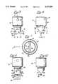
These and other features of the invention are attained by providing a driving tool comprising: a shaft having a longitudinal axis, a driving blade at one end of said shaft defined by front and rear surfaces and a pair of side surfaces and an arcuately convex distal end surface intersecting said front and rear surfaces and said side surfaces, said blade having a width which is the distance between said side surfaces at their intersections with said end surface, said end surface having a radius of curvature centered on said longitudinal axis, said radius of curvature being greater than said width.
The invention consists of certain novel features and a combination of parts hereinafter fully described, illustrated in the accompanying drawings, and particularly pointed out in the appended claims, it being understood that various changes in the details may be made without departing from the spirit, or sacrificing any of the advantages of the present invention.
BRIEF DESCRIPTION OF THE DRAWINGS
For the purpose of facilitating an understanding of the invention, there are illustrated in the accompanying drawings preferred embodiments thereof, from an inspection of which, when considered in connection with the following description, the invention, its construction and operation, and many of its advantages should be readily understood and appreciated.
FIG. 1 is a fragmentary sectional view illustrating the engagement of a prior art high torque driving tool with an associated fastener;
FIG. 2 is a fragmentary sectional view taken generally along theline 2--2 in FIG. 1;
FIG. 3 is a front elevational view of a driving tool constructed in accordance with and embodying the features of a first embodiment of the present invention;
FIG. 4 is a side elevational view of the driving tool of FIG. 3;
FIG. 5 is a view similar to FIG. 3, showing the tool engaged in the driving slot of an associated fastener which is illustrated in section;
FIG. 6 is a fragmentary view in vertical section taken along theline 6--6 in FIG. 5;
FIG. 7 is an enlarged view in horizontal section taken along theline 7--7 in FIG. 4;
FIG. 8 is an enlarged fragmentary view of the lower end of the blade of the tool illustrated in FIG. 6;
FIG. 9 is a fragmentary front elevational view of a prior art driving tool with a conical centering tip, shown illustrated in the driving slot of an associated fastener which is illustrated in section;
FIG. 10 is a fragmentary side elevational view in partial section of the driving tool of FIG. 9;
FIG. 11 is a view similar to FIG. 5, illustrating a driving tool in accordance with another embodiment of the invention, shown engaged in the driving slot of an associated fastener; and
FIG. 12 is a fragmentary side elevational view of the driving tool of FIG. 11.
DESCRIPTION OF THE PREFERRED EMBODIMENTS
Referring to FIGS. 1 and 2, there is illustrated a prior art hightorque driving tool 10 having ablade 11 with front andrear surfaces 12 and 13 interconnected byside surfaces 14 and by an arcuatelyconvex end surface 15. The lower ends of the front andrear surfaces 12 and 13 diverge slightly toward theend surface 15, as at 16, and toward theside surfaces 14, resulting in a generally bow tie-shaped configuration. Thedriving tool 10 is adapted for use with an associatedfastener 20 having a threadedshank 21 provided with ahead 22 at one end thereof which has a drivingface 23 in which is formed adriving slot 25. Thedriving slot 25 has slightlyundercut side walls 26 with outwardly flaredend portions 27 and an arcuatelyconcave bottom wall 28, the opposite ends of which respectively intersect the drivingface 23.
Thus, it can be seen that theblade 11 and thedriving slots 25 have generally complementary bow tie shapes so that theblade 11 is matingly received in thedriving slot 25. More specifically, the radius of curvature of theblade end surface 15 is substantially the same as that of the drivingslot bottom wall 28 so that theblade 11 bottoms in theslot 25. Typically, theblade 11 has a width which is at least as great as the length of thedriving slot 25. Thus, in high torque applications, there is a tendency for theblade 11 to cam out of thedriving slot 25 adjacent to the shallow opposite ends thereof. This tendency is aggravated if there is dirt or other debris in thedriving slot 25 which prevents theblade 11 from bottoming on the drivingslot bottom wall 28 and further reduces the depth of engagement.
Referring now to FIGS. 3-8, there is illustrated adriving tool 30 constructed in accordance with and embodying the features of a first embodiment of the present invention, which avoids the disadvantages of the prior art construction. Thedriving tool 30 has anelongated shaft 31 which is generally circularly cylindrical in shape (although it is known to provide a hexagonal shaft, as in a bit constructions, having a longitudinal axis "X" (FIG. 3). Theshaft 31 has amain body 33, in one end of which is formed an axial socket 34 (FIG. 6), of known construction, communicating with aradial bore 35 in the side wall of themain body portion 33. Theshaft 31 is provided at its other end with a reduced-diameter portion 37 which is joined to themain body portion 33 by atapered transition portion 36. Formed at the distal end of the reduced-diameter portion 37 is ablade 40 which has front andrear surfaces 41 and 42 interconnected byside surfaces 43 and 44 and by an arcuatelyconvex end surface 45. Theend surface 45 has a radius of curvature R1 which is centered on the longitudinal axis "X" (FIG. 3) and which is substantially greater than the radius of curvature R2 of thebottom surface 28 of the fastener driving slot 25 (see FIG. 5). Each of the front andrear surfaces 41 and 42 has an substantiallyflat portion 46 at its upper end, and an arcuatelyconcave portion 47 at its lower end. Theportions 46 converge downwardly, while theportions 47 diverge slightly toward theend surface 45.
The concavelower portion 47 of each of the front andrear surfaces 41 and 42 has a dual concavity. More specifically each lowerconcave portion 47 has a first radius of curvature R3 centered about an axis "Y" which is substantially orthogonal to the axis "X", i.e., perpendicular to the plane of the paper in FIG. 6, and a second radius of curvature R4 centered on an axis "Z" which is substantially parallel to the axis "X", i.e., perpendicular to the plane of the paper in FIG. 7. In the cross sections of FIGS. 6 and 8 theconcave portions 47 respectively terminate inend portions 47a which are generally part frustoconical in shape so that, in the cross section of FIG. 8, they define substantially straight lines diverging slightly toward theend surface 45. The R4 concavity causes theconcave portions 47, including theirend portions 47a, to diverge slightly toward theside surfaces 43 and 44, producing a generally bow tie-shaped configuration.
Theconvex end surface 45 intersects theside surfaces 43 and 44, respectively, atcorner edges 48 and 49 (see FIG. 3). Theblade 40 has a width W which is the distance between thecorner edges 48 and 49. Theblade 40 also has a thickness T, which is the distance between the front andrear surfaces 14 and 42 at their intersections with theend surface 45, midway between the side surfaces 43 and 44 (see FIG. 4). It is a significant aspect of the invention that the radius curvature R1 of the end surface 45 (FIG. 3) is greater than the width W of theblade 40. It will be appreciated that theblade 40 may be provided in a number of different sizes, and the ratio R1/W may vary somewhat from one size blade to another, but the ratio is always preferably between one and two. Preferably also the width W is less than the length of the drivingslot 25 in the associatedfastener 20.
These dimensional relationships produce significant functional advantages. Referring to FIGS. 5 and 6, it can be seen that when theblade 40 is inserted in the drivingslot 25 it engages thebottom wall 28 of the drivingslot 25 only at the corner edges 48 and 49 and at a significant depth D below the drivingface 23. This serves to greatly minimize the tendency of theblade 40 to cam out of the driving slot in high torque applications. Furthermore, it can be seen that the difference in the radii R1 and R2 results in a significant clearance space C between theblade end surface 45 and the drivingslot bottom wall 28. This permits accumulation of dirt or other debris in the bottom of the drivingslot 25 without significantly affecting the depth of insertion of theblade 40 in the drivingslot 25.
Referring now to FIGS. 9 and 10, there is illustrated another type of prior art driving tool, generally designated by the numeral 50, which is similar to the priorart driving tool 10, except that thetool 50 has ablade 51 with front and rear surfaces 52 (one shown), each of which has a planarupper portion 53 and an arcuately concavelower portion 54. Theblade 51 is also provided with aconical tip 55 substantially coaxial with the longitudinal axis of the drivingtool 50 and which projects axially beyond the end surface of theblade 51. Theconical tip 50 also extends axially inboard of the end surface of theblade 51 to a base 56 which has a diameter substantially greater than the thickness of theblade 51, and then continues into a generallycylindrical portion 57 which extends upwardly to theplanar portions 53 of the front andrear surfaces 52.
The drivingtool 50 is adapted for engagement with afastener 60 which is substantially the same as thefastener 20, described above, except that it has a drivingslot 65 provided centrally thereof with aconical recess 69 which extends upwardly all the way to the drivingface 23. In use, when theblade 51 is to be engaged in the drivingslot 65, theconical tip 55 engages in theconical recess 69 to properly center theblade 51 in the drivingslot 65. This greatly facilitates the proper alignment of theblade 51 with the drivingslot 65, and permits engagement of the parts by "feel" if, for example, the user cannot clearly see the drivingslot 65. However, the drivingtool 50 is very difficult and expensive to manufacture, typically requiring the use of costly investment casting techniques.
Referring now also to FIGS. 11 and 12, there is illustrated adriving tool 70 in accordance with a second embodiment of the present invention, adapted for use with the conically recessedfastener 60. The drivingtool 70 is substantially identical to thedriving tool 30, described above in connection with FIGS. 3-8, except that it is provided with aconical tip 75 coaxial with the longitudinal axis "X" of the drivingtool 70 and projecting axially from theend surface 45 of theblade 40. Theconical tip 75 has a base 76 which is disposed at theend surface 45 and has a base diameter which is substantially the same as the thickness T of theblade 40. It will be appreciated that theconical tip 75 is dimensioned and disposed for centering engagement in theconical recess 69 of thefastener 60, thereby to serve the same centering function as was described above in connection with the priorart driving tool 50. However, because theconical tip 75 does not extend axially inboard of theend surface 45 and does not extend forwardly and rearwardly outboard of theend surface 45, it can be formed by the same milling cutters and other equipment used to form the drivingtool 30, significantly reducing the cost of manufacture as compared with the priorart driving tool 50. Also, since the base diameter of theconical tip 75 is substantially smaller than that of the prior artconical tip 55, theconical recess 69 in thefastener 60 need not extend laterally beyond the side walls of the drivingslot 65.
From the foregoing, it can be seen that there has been provided an improved high torque driving tool which is of simple and economical construction and which is adapted for engagement with mating high torque fasteners so as to substantially reduce the tendency to cam out of the fastener slot.

Claims (6)

We claim:
1. A driving tool comprising: a shaft having a longitudinal axis, a driving blade at one end of said shaft defined by front and rear surfaces and a pair of side surfaces and an arcuately convex distal end surface intersecting said front and rear surfaces and said side surfaces, each of said front and rear surfaces being arcuately concave about an axis of curvature which is disposed substantially parallel to said longitudinal axis of said shaft, each of said front and rear surfaces being arcuately concave about an axis of curvature which is substantially orthogonal to the longitudinal axis of the shaft, said blade having a width which is the distance between said side surfaces at their intersections with said end surface, said end surface having a radius of curvature centered on said longitudinal axis, said radius of curvature being greater than said width.
2. The driving tool of claim 1, wherein the ratio said radius to said width is between one and two.
3. The driving tool of claim 1, said blade having a thickness which is the distance between said front and rear surfaces at their intersections with said end surface and midway between said side surfaces, and further comprising a generally conical tip formed on said blade substantially coaxial with said shaft and projecting axially from said end surface, said tip having a base at said end surface circular in transverse cross section with a diameter no greater than said thickness of said blade.
4. A driving tool for use in combination and relative high torque engagement with a fastener having a head at one end of a threaded shank, said head having a driving face in which is recessed a driving slot of generally bow tie configuration defined by at least slightly undercut side walls and an arcuately concave bottom wall having a radius of curvature centered on the longitudinal axis of the shank, the slot having a length which is the distance between the intersections of the bottom wall with the driving face as measured along the driving face, said driving tool comprising: a tool shaft having a longitudinal axis, a driving blade at one end of said shaft defined by front and rear surfaces and a pair of side surfaces and an arcuately convex distal end surface intersecting said front and rear surfaces and said side surfaces, each of said front and rear surfaces being arcuately concave about an axis of curvature which is disposed substantially parallel to said longitudinal axis of said shaft, each of said front and rear surfaces being arcuately concave about an axis of curvature which is substantially orthogonal to the longitudinal axis of the shaft, said blade having a width which is the distance between said side surfaces at their intersections with said end surface, said end surface having a radius of curvature centered on said longitudinal axis of said shaft, said width of said blade being substantially less than the length of the slot, said radius of curvature of said blade end surface being greater than the radius of curvature of the bottom wall of the slot.
5. The driving tool of claim 4, and further comprising a generally conical tip formed on said blade substantially coaxial with said shaft and projecting axially from said end surface.
6. The driving tool of claim 5, wherein said blade has a thickness which is the distance between said front and rear surfaces at their intersections with said end surface and midway between said side surfaces, said tip having a base at said end surface circular in transverse cross section with a diameter substantially equal to said thickness of said blade.
US08/023,5531993-02-261993-02-26Arcuate tip driverExpired - LifetimeUS5347893A (en)

Priority Applications (2)

Application NumberPriority DateFiling DateTitle
US08/023,553US5347893A (en)1993-02-261993-02-26Arcuate tip driver
US08/190,849US5367926A (en)1993-02-261994-02-03Arcuate tip driver

Applications Claiming Priority (1)

Application NumberPriority DateFiling DateTitle
US08/023,553US5347893A (en)1993-02-261993-02-26Arcuate tip driver

Related Child Applications (1)

Application NumberTitlePriority DateFiling Date
US08/190,849DivisionUS5367926A (en)1993-02-261994-02-03Arcuate tip driver

Publications (1)

Publication NumberPublication Date
US5347893Atrue US5347893A (en)1994-09-20

Family

ID=21815811

Family Applications (2)

Application NumberTitlePriority DateFiling Date
US08/023,553Expired - LifetimeUS5347893A (en)1993-02-261993-02-26Arcuate tip driver
US08/190,849Expired - LifetimeUS5367926A (en)1993-02-261994-02-03Arcuate tip driver

Family Applications After (1)

Application NumberTitlePriority DateFiling Date
US08/190,849Expired - LifetimeUS5367926A (en)1993-02-261994-02-03Arcuate tip driver

Country Status (1)

CountryLink
US (2)US5347893A (en)

Cited By (5)

* Cited by examiner, † Cited by third party
Publication numberPriority datePublication dateAssigneeTitle
US5857215A (en)*1994-07-011999-01-12Ilixco, Inc.Helmet with high performance head and face protection utilizing molded composite materials and method
US20040031360A1 (en)*2002-08-142004-02-19Chien-Cheng HerHex wrench
US20050109171A1 (en)*2003-11-242005-05-26Sergei ShapovalFastener and driving tool with retaining blade
US20110173760A1 (en)*2010-01-192011-07-21John Watley LamarHandle-operated tool with a multi-function tool tip employable for one more purposes on different irrigation-related products
US20130327188A1 (en)*2012-06-112013-12-12Roger F. WilsonSlip-resistant screwdriver for slotted screws and method for driving slotted screws

Families Citing this family (11)

* Cited by examiner, † Cited by third party
Publication numberPriority datePublication dateAssigneeTitle
RU2117571C1 (en)*1996-12-151998-08-20Михаил Миронович ЗурикьянScrew driver
US6162225A (en)*1998-10-262000-12-19Musculoskeletal Transplant FoundationAllograft bone fixation screw method and apparatus
US6099529A (en)1998-10-262000-08-08Musculoskeletal Transplant FoundationAllograft bone fixation screw method and apparatus
FR2827016B1 (en)2001-07-042004-07-09Ge Med Sys Global Tech Co Llc QUARTER-TURN DEVICE FOR FIXING A COVER OR A SIMILAR ELEMENT ON A STRUCTURAL ELEMENT, IN PARTICULAR IN THE FIELD OF MEDICAL DEVICES
US20030200842A1 (en)*2002-04-302003-10-30Iannone Pasquale AnthonyHand tool device for use in the operation of quarter turn spring loaded self-ejecting or non spring loaded button type fasteners
US20050076749A1 (en)*2003-10-102005-04-14Liu Kuo ChenDriving tool member having anti-slip device
US20060130621A1 (en)*2004-11-222006-06-22Irwin Industrial Tool CompanyMulti-tool screwdriver
US7690282B2 (en)*2005-08-032010-04-06Synthes Usa, LlcScrew-retaining screwdriver
CN103282162B (en)2010-07-072017-10-13英法斯泰克知识产权私人有限公司Torque transmission driver
US10968939B2 (en)2011-08-252021-04-06Infastech Intellectual Properties Pte. Ltd.Tapered lobular driver and fastener
CA2846336C (en)2011-08-252021-02-23Infastech Intellectual Properties Pte. Ltd.Tapered lobular driver and fastener

Citations (16)

* Cited by examiner, † Cited by third party
Publication numberPriority datePublication dateAssigneeTitle
US370255A (en)*1887-09-20Daniel e
US1361790A (en)*1919-11-181920-12-07Hugh C BrownValve and grinding mechanism therefor
US1899489A (en)*1931-10-021933-02-28Wickbergh GodfreyScrew driver
US2631624A (en)*1950-02-251953-03-17Roland H WrightScrew driver
US2677985A (en)*1949-07-111954-05-11Hi Shear Rivet Tool CoSlotted screwhead
US2808087A (en)*1955-07-181957-10-01Rudolph M VaughnScrew driver
US3175593A (en)*1961-03-311965-03-30Launay PierreScrewdriver blade
US3695321A (en)*1970-06-301972-10-03Jacob W Garehime JrCavity head screw and driving tool therefor
US3891017A (en)*1973-03-151975-06-24Marian IskraCombination screw and screwdriver with axial guide spigot
US4325153A (en)*1979-10-221982-04-20Charles FinneganCombined screwdriver and boring apparatus
US4528874A (en)*1983-01-171985-07-16Dunn J MalcolmScrew fasteners and drivers
US4590825A (en)*1983-05-061986-05-27John VaughnHigh torque fastener and driving tool
US4625598A (en)*1985-05-101986-12-02Frank WolframPositive engagement screw driver tool
US4670927A (en)*1983-05-061987-06-09John VaughnMethod and apparatus for forming the head of a high torque fastener
US4977800A (en)*1988-12-301990-12-18Colvin David SScrewdriver blade construction
US4998454A (en)*1988-11-141991-03-12Black & Decker Inc.Screwdriver bit for phillips-head fasteners

Patent Citations (16)

* Cited by examiner, † Cited by third party
Publication numberPriority datePublication dateAssigneeTitle
US370255A (en)*1887-09-20Daniel e
US1361790A (en)*1919-11-181920-12-07Hugh C BrownValve and grinding mechanism therefor
US1899489A (en)*1931-10-021933-02-28Wickbergh GodfreyScrew driver
US2677985A (en)*1949-07-111954-05-11Hi Shear Rivet Tool CoSlotted screwhead
US2631624A (en)*1950-02-251953-03-17Roland H WrightScrew driver
US2808087A (en)*1955-07-181957-10-01Rudolph M VaughnScrew driver
US3175593A (en)*1961-03-311965-03-30Launay PierreScrewdriver blade
US3695321A (en)*1970-06-301972-10-03Jacob W Garehime JrCavity head screw and driving tool therefor
US3891017A (en)*1973-03-151975-06-24Marian IskraCombination screw and screwdriver with axial guide spigot
US4325153A (en)*1979-10-221982-04-20Charles FinneganCombined screwdriver and boring apparatus
US4528874A (en)*1983-01-171985-07-16Dunn J MalcolmScrew fasteners and drivers
US4590825A (en)*1983-05-061986-05-27John VaughnHigh torque fastener and driving tool
US4670927A (en)*1983-05-061987-06-09John VaughnMethod and apparatus for forming the head of a high torque fastener
US4625598A (en)*1985-05-101986-12-02Frank WolframPositive engagement screw driver tool
US4998454A (en)*1988-11-141991-03-12Black & Decker Inc.Screwdriver bit for phillips-head fasteners
US4977800A (en)*1988-12-301990-12-18Colvin David SScrewdriver blade construction

Cited By (7)

* Cited by examiner, † Cited by third party
Publication numberPriority datePublication dateAssigneeTitle
US5857215A (en)*1994-07-011999-01-12Ilixco, Inc.Helmet with high performance head and face protection utilizing molded composite materials and method
US20040031360A1 (en)*2002-08-142004-02-19Chien-Cheng HerHex wrench
US20050109171A1 (en)*2003-11-242005-05-26Sergei ShapovalFastener and driving tool with retaining blade
US7165482B2 (en)*2003-11-242007-01-23Sergei ShapovalFastener and driving tool with retaining blade
US20110173760A1 (en)*2010-01-192011-07-21John Watley LamarHandle-operated tool with a multi-function tool tip employable for one more purposes on different irrigation-related products
US8544370B2 (en)*2010-01-192013-10-01John Watley LamarHandle-operated tool with a multi-function tool tip employable for one or more purposes on different irrigation-related products
US20130327188A1 (en)*2012-06-112013-12-12Roger F. WilsonSlip-resistant screwdriver for slotted screws and method for driving slotted screws

Also Published As

Publication numberPublication date
US5367926A (en)1994-11-29

Similar Documents

PublicationPublication DateTitle
US5347893A (en)Arcuate tip driver
EP1847345B1 (en)A tool for chip removing metal machining and part therefor
CN102123831B (en)A kind of combination driven tool for Philips and Luo Baisheng securing member
JP4493135B2 (en) Screw and driver bit combination
US5086674A (en)Multi-purpose hand tool
EP2484469B1 (en)Cutting tool
AU2001244500B2 (en)Tool joint
RU2262011C2 (en)Screwing device
TW401489B (en)Combination of screw with driver bit or wrench
JP2656949B2 (en) Metal cutting tools
US20030059276A1 (en)Screw socket opening for receiving various tool bits
EP1080846A1 (en)Screwdriver bit and its combination with screw
ZA200610821B (en)Drill with releasably mounted cutting head
EP0992694B1 (en)Thread insert having detachable tongue
US5001948A (en)Screwdriver blade with curved tip
US2792039A (en)Slotted screw head and driver therefor having non-burring engagement
US3675694A (en)Screw and screw driver combination
US4716797A (en)Screwdriver with concave blade
JPH0321845Y2 (en)
US4977800A (en)Screwdriver blade construction
JP4394184B2 (en) Combination with screwdriver bit and screw
JPWO2004065067A1 (en) Combination with screwdriver bit and screw
JPH10131930A (en)Combination of +/-screw and driver bit
JP4130259B2 (en) Phillips screwdriver bit
JP2526213Y2 (en) Cutting tools

Legal Events

DateCodeTitleDescription
ASAssignment

Owner name:SNAP-ON TOOLS CORPORATION, WISCONSIN

Free format text:ASSIGNMENT OF ASSIGNORS INTEREST.;ASSIGNORS:MIKIC, FRANK;HOFF, JEFFERY H.;REEL/FRAME:006456/0800

Effective date:19930129

ASAssignment

Owner name:SNAP-ON INCORPORATED, WISCONSIN

Free format text:ASSIGNMENT OF ASSIGNORS INTEREST;ASSIGNOR:SNAP-ON TOOLS CORPORATION;REEL/FRAME:007013/0511

Effective date:19940422

ASAssignment

Owner name:SNAP-ON INCORPORATED, WISCONSIN

Free format text:CERTIFICATE OF AMENDMENT OF SNAP-ON TOOLS CORPORATION CHANGING ITS NAME EFFECTIVE 4-22-94;ASSIGNOR:SNAP-ON TOOLS CORPORATION;REEL/FRAME:007113/0747

Effective date:19940422

STCFInformation on status: patent grant

Free format text:PATENTED CASE

ASAssignment

Owner name:SNAP-ON TOOLS WORLDWIDE, INC., ILLINOIS

Free format text:ASSIGNMENT OF ASSIGNORS INTEREST;ASSIGNOR:SNAP-ON INCORPORATED;REEL/FRAME:007881/0532

Effective date:19951229

Owner name:SNAP-ON TECHNOLOGIES, INC., ILLINOIS

Free format text:ASSIGNMENT OF ASSIGNORS INTEREST;ASSIGNOR:SNAP-ON TOOLS WORLDWIDE, INC.;REEL/FRAME:007881/0588

Effective date:19951229

FPAYFee payment

Year of fee payment:4

FEPPFee payment procedure

Free format text:PAYOR NUMBER ASSIGNED (ORIGINAL EVENT CODE: ASPN); ENTITY STATUS OF PATENT OWNER: LARGE ENTITY

FPAYFee payment

Year of fee payment:8

ASAssignment

Owner name:SNAP-ON INCORPORATED, WISCONSIN

Free format text:MERGER;ASSIGNOR:SNAP-ON TECHNOLOGIES, INC.;REEL/FRAME:015209/0414

Effective date:20031219

FPAYFee payment

Year of fee payment:12


[8]ページ先頭

©2009-2025 Movatter.jp