US5347211A - Selectable output power converter - Google Patents
Selectable output power converterDownload PDFInfo
- Publication number
- US5347211A US5347211AUS08/030,670US3067093AUS5347211AUS 5347211 AUS5347211 AUS 5347211AUS 3067093 AUS3067093 AUS 3067093AUS 5347211 AUS5347211 AUS 5347211A
- Authority
- US
- United States
- Prior art keywords
- key
- converter
- power converter
- recited
- voltage
- Prior art date
- Legal status (The legal status is an assumption and is not a legal conclusion. Google has not performed a legal analysis and makes no representation as to the accuracy of the status listed.)
- Expired - Lifetime
Links
- 238000012544monitoring processMethods0.000claimsdescription8
- 239000003990capacitorSubstances0.000claimsdescription2
- 238000007664blowingMethods0.000description4
- 238000006243chemical reactionMethods0.000description4
- 238000000034methodMethods0.000description4
- 230000001105regulatory effectEffects0.000description4
- LLQPHQFNMLZJMP-UHFFFAOYSA-NFentrazamideChemical compoundN1=NN(C=2C(=CC=CC=2)Cl)C(=O)N1C(=O)N(CC)C1CCCCC1LLQPHQFNMLZJMP-UHFFFAOYSA-N0.000description3
- 230000004397blinkingEffects0.000description3
- 230000007812deficiencyEffects0.000description3
- 238000005286illuminationMethods0.000description3
- 230000004048modificationEffects0.000description3
- 238000012986modificationMethods0.000description3
- 239000002253acidSubstances0.000description2
- 238000007792additionMethods0.000description2
- 230000008901benefitEffects0.000description2
- 235000019504cigarettesNutrition0.000description2
- 238000001816coolingMethods0.000description2
- 230000002950deficientEffects0.000description2
- 238000007599dischargingMethods0.000description2
- 238000003780insertionMethods0.000description2
- 230000037431insertionEffects0.000description2
- 238000006748scratchingMethods0.000description2
- 230000002393scratching effectEffects0.000description2
- 241001422033ThestylusSpecies0.000description1
- 230000004075alterationEffects0.000description1
- 230000009286beneficial effectEffects0.000description1
- 238000001914filtrationMethods0.000description1
- 230000008569processEffects0.000description1
- 230000035755proliferationEffects0.000description1
- 238000009877renderingMethods0.000description1
Images


Classifications
- G—PHYSICS
- G05—CONTROLLING; REGULATING
- G05F—SYSTEMS FOR REGULATING ELECTRIC OR MAGNETIC VARIABLES
- G05F1/00—Automatic systems in which deviations of an electric quantity from one or more predetermined values are detected at the output of the system and fed back to a device within the system to restore the detected quantity to its predetermined value or values, i.e. retroactive systems
- G05F1/10—Regulating voltage or current
- G05F1/46—Regulating voltage or current wherein the variable actually regulated by the final control device is DC
- G05F1/56—Regulating voltage or current wherein the variable actually regulated by the final control device is DC using semiconductor devices in series with the load as final control devices
- G05F1/575—Regulating voltage or current wherein the variable actually regulated by the final control device is DC using semiconductor devices in series with the load as final control devices characterised by the feedback circuit
Definitions
- the present inventionrelates generally to power converters and more particularly to a power converter for use with laptop computers and the like having an output voltage which is selectable by inserting an electronic key corresponding to the desired voltage into a keyway disposed within the converter.
- Converters for converting the output voltages of AC or DC sources into a voltage having a particular desired valueare well-known.
- laptop computers and the likecommonly use such a power converter which plugs into a common wall outlet and electrically connects to the laptop computer.
- a step-down transformer and rectifying circuitare typically disposed within a housing to which the power plug is attached to facilitate electrical interconnection with the wall outlet.
- a filtering circuitmay also be disposed within the housing.
- adapters or power converters for facilitating the use of laptop computers and the like from 12 volt DC sourcesare likewise well-known.
- Such power converterscontain the necessary circuitry for converting the 12 volt DC source voltage to a voltage suitable for powering the electrical device.
- prior art deviceshave been constructed so as to provide selectable output voltages.
- Such prior art devicesutilize a switch formed thereon for facilitating selection of the desired output voltage.
- the use of such a switchinherently makes it possible to select an incorrect output voltage.
- the selection of such an incorrect output voltagemay potentially damage the device powered thereby. This is particularly true if the incorrectly selected output voltage is higher than that required by the device powered thereby.
- the incorrect output voltagemay be inadvertently selected by the user prior to utilizing such prior art selectable output voltage power converters or, alternatively, may accidentally be changed, i.e., via mishandling, after use thereof has commenced.
- Model MW182 800 mA Regulated DC Adaptermanufactured by Minwa of Taiwan. This device provides the ability to convert the power output from a car cigarette lighter, i.e., 12 volts DC, to any one of the following outputs: 1.5, 3, 4.5, 6, 7.5 9, or 12 volts DC.
- the present inventionspecifically addresses and alleviates the above-mentioned deficiencies associated with the prior art. More particularly, the present invention comprises a power converter for providing a selectable, desired voltage for a laptop computer or other such electrically powered device.
- the selectable output power converterhas a converter circuit having an input port for receiving an input of a first voltage and an output port for providing an output of a second voltage.
- the converter circuitalso has a keyway for receiving a key.
- a plurality of keysare provided, each key being used to cause the converter circuit to output a different voltage.
- the keywhich is configured to be received by the keyway, contains an electrical component and has a body within which the electrical component is disposed.
- the output voltage of the converteris determined by the value of the electrical component disposed within the body of the key such that the output voltage can be varied by replacing the key with another key having an electrical component of a different value.
- the keyis preferably configured such that it will be marred, marked, rendered inoperative, or otherwise made indicative of prior use, once removed from the selectable power converter of the present invention. This eliminates the potential for a user, either through inadvertence or intention, to utilize a key resulting an output from the converter which is incorrect, i.e., too high, for the device so powered, thus resulting in damage to the device.
- the electrical component of the keyis used in feedback circuitry to set the output voltage.
- the converter circuitpreferably utilizes a selectable voltage pulse width modulator (PWM) regulator. Overvoltage protection is utilized to limit damage due to a defective integrated circuit chip or other electrical component of the converter circuit.
- PWMpulse width modulator
- Such overvoltage protectionmay be implemented by providing transistors which short out the input voltage to ground, thus causing an internal, non-replaceable fuse to open, when a reference voltage of an operational amplifier exceeds a selected value. This would occur only as a result of a catastrophic failure of the converter circuitry, wherein it would be assumed that the converter circuitry can no longer function reliably and should be disabled.
- the output voltagemay simply be monitored such that if an overvoltage condition is indicated, then an internal fuse is blown.
- an overvoltage conditionmay be indicated by the sensing of a voltage, for example of approximately 0.5 volts greater than the desired output voltage.
- overvoltagemay be indicated by monitoring for deviations of a normally steady-state reference voltage, i.e., 1.25 volt DC. Deviations from the nominal value indicate an overvoltage condition.
- input overvoltage protectionmay be utilized to prevent damage due to excessive input voltage or long duration high voltage spikes. For example, if the DC input voltage exceeds approximately 18 volts, then a zener diode conducts to turn on transistors which short the input to ground. Shorting of the input to ground results in a fuse blowing and consequent discontinuance of the output of the converter circuitry.
- the input overvoltage protectionpreferably causes the converter circuit to clamp down voltage spikes up to 75 volts and having durations of 10 milliseconds.
- a low battery warning circuitis preferably utilized to indicate to the user that the source battery voltage has fallen below a predetermined level.
- low battery warningmay be accomplished by utilizing an LED which glows steadily when the unit is energized and which blinks when the source voltage drops below approximately 11 volts.
- a low battery voltage shut-offturns off the output voltage when the input voltage falls below a predetermined level, i.e., 10.5 volts. This prevents damage from excessively discharging sealed lead-acid batteries and the like.
- the indicator LEDwill stop blinking, to indicate a low battery condition, and remain off, thus indicating that the power converter has shut down.
- the selectable output power converter of the present inventionmay optionally be configured to mechanically and electrically attach to a portable DC power source such as the 12-volt DC cordless rechargeable POWERPAK sold by Innova of Fountain Valley, Calif.
- a portable DC power sourcesuch as the 12-volt DC cordless rechargeable POWERPAK sold by Innova of Fountain Valley, Calif.
- the track of the selectable output power converter of the present inventionis specifically configured to slidably engage a complimentary track formed upon the POWERPAK. Electrical contacts formed upon the track of the selectable power converter of the present invention and corresponding electrical contacts formed upon the track of the POWERPAK facilitate electrical interconnection thereof.
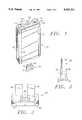
- FIG. 1is a perspective view of the power converter of the present invention illustrating insertion of the key into the keyway thereof;
- FIG. 2is an enlarged front view of the key of FIG. 1;
- FIG. 3is an enlarged side view of the key of FIGS. 1 and 2;
- FIG. 4is cross-sectional side view of the converter means of FIG. 1 showing the key inserted within the keyway thereof;
- FIG. 5is a top plan view of the converter means of FIGS. 1 and 4;
- FIG. 6is an electrical schematic of the converter means and key of the present invention.
- FIG. 7is a fragmentary perspective view of a POWERPAK showing the track formed thereon for facilitating attachment to the present invention.
- FIG. 8is an enlarged top view showing engagement of the tracks of the POWERPAK with the tracks of the present invention.
- the selectable output power converter of the present inventionis illustrated in FIGS. 1 through 6 which depict a presently preferred embodiment of the invention.
- the selectable output power converter of the present inventiongenerally comprises a converter 10 having a housing 12.
- An input jack 14 and an output jack 16are formed upon the case, preferably the upper end 18 thereof.
- An indicator, preferably a rectangular LED 20,is formed upon the case proximate the input 14 and output 16 jacks.
- the input 14 and output 16 jackspreferably comprise standard mini-jacks such as those commonly used with items powered by contemporary AC to DC converters.
- cooling fins 22are formed upon the sides 24 of the case 10 to facilitate cooling of the converter circuit (as shown in FIG. 6) contained therein.
- Attachment means or track 26 formed upon the rear 28 of the converter 10facilitates attachment thereof to a battery power pack such as Model 06-1101 manufactured by Innova Electronics, Inc. of Fountain Valley, Calif.
- a key 30is removably insertable into a keyway 32 (as best seen in FIG. 4) of the converter 10.
- the key 30contains an electrical component 38 (as shown in FIGS. 2 and 3), preferably a resistor, the value of which determines the output voltage of the converter 10.
- the body 34 of the key 30may optionally be the electrical component 38 itself, thus eliminating the need to fabricate a separate body.
- the key 30is preferably configured in a manner like that of blade-type automobile fuses.
- the key 30comprises a body 34 and two blades 36 which are received within the keyway 32.
- the key 30is preferably configured such that removal thereof from the keyway 32 results in an indication of removal being formed upon the key.
- the indication of removalmay comprise marring, scratching, marking, or any other modification or alteration of the key which may serve as an indication that the key has been previously installed into a converter 10 and then removed therefrom.
- the keymay be configured such that removal thereof from the keyway results from breakage of the key 30 such that the key 30 becomes inoperative and a converter into which it is subsequently installed will not function or alternatively functions only on the lowest output voltage.
- Marring, scratching, or marking of the keymay be accomplished, for example, by providing a stylus 37 within the body 12 of the converter 10 such that a sharp tip 39 of the stylus abuts and scrapes, marks, or mars the body of the key 30 as the key 30 is inserted and removed from the keyway 32.
- Breakage of the key 30may be accomplished by provided a barb or detent means (not shown) within the body 12 of the converter 10 such that the barb or detent engages a portion of the key 30.
- the key 30is configured to have a structural weakness such that removal of the key 30 from the converter 10 results in breakage thereof as the barb or detent maintains engagement thereof during the withdrawal process. That is, a portion of the key 30 is engaged by the barb or detent of the converter 10 and is only released upon breakage of the key 30.
- the electrical component 38is electrically interconnected to the blades 36 such that a circuit is formed serially through the blades 36 and the electrical component 38.
- Indiciaare optionally formed upon the upper surface 40 of the body 34 indicative of the output voltage which results from insertion of the key 30 into the converter 10.
- the electrical component 38preferably comprises a resistor
- various electrical componentsi.e., capacitors, inductors, etc.
- the electrical componenthave a readily identifiable value such that the electrical circuitry of the charger 36 can determine therefrom the desired output voltage.
- a key 30has been inserted into the keyway 32 of the converter 10.
- the converter 10has been enabled to provide an output voltage as determined by the value of the electrical component 36 disposed within the body 34 of the key 30.
- the keyway 32is attached to a printed circuit board 42 via legs 44.
- the electrical components of the converter circuit(as shown in FIG. 6) are generally disposed upon the printed circuit board 42.
- Electrical contacts 46extend from the printed circuit board 42 and provide electrical interconnection to the battery power pack, if the battery pack is attached to the power converter 10 via the track 26.
- FIG. 6a representative converter circuit is illustrated. Those skilled in the art will recognize that various other converter circuits are likewise suitable. Indeed, converter circuits are contemplated for DC-DC conversion, AC-DC conversion, DC-AC conversion, and AC-AC conversion.
- the converter circuitpreferably comprises feedback circuitry in which the electrical component 38 of the key 30 is utilized to set the output voltage thereof.
- the absence of any electrical component 38 within a keyresults in the output of the feedback circuitry being minimal, i.e., 1.5 volts.
- the selectable output power converter of the present inventionmay optionally be operable at its lowest output voltage with no key installed therein.
- the selectable output power converter of the present inventiongenerally comprises an input overvoltage protection circuit 50, a selectable voltage key circuit 52, a low battery voltage shut-off circuit 54, a low battery warning circuit 56, and an output overvoltage protection circuit 58.
- the selectable voltage key circuit 52comprises a user removable key 30 having an electrical component disposed therein, preferably a resistor 38, and is preferably configured similar to a blade-type car fuse.
- the resistor 38 of the key 30replaces the fusing link of the blade-type car fuse.
- the resistor 38is used in the feedback portion of the voltage regulator to select the output voltage. The advantage of this method is that the desired voltage can easily be selected any time.
- Selectable voltage pulse width modulator (PWM) regulator integrated circuit chip 60provides a regulated output at the voltage determined by resistor 38.
- the resistor 38may have values of 5.2K ohm, 4.7K ohm, or 3.9k ohm to provide output voltages of 6.0 volts DC, 7.5 volts DC, or 9.0 volts DC respectively.
- Resistor 62is in parallel with the resistor 38 of the key 30 such that an output voltage of 3.3 volts DC will be provided if no key 30 is inserted.
- the converter circuitmay be configured to provide any other desired output voltage, including zero output, when no key is installed.
- the key 30may contain one or more jumpers to define the desired output of the selectable power converter of the present invention.
- the output overvoltage protection circuit 58is provided so as to limit any damage caused to a device powered by the selectable power converter of the present invention due to a defective component, i.e., integrated circuit, of the power converter.
- the voltage at pin 5 of integrated circuit 60will always have the steady-state nominal value of 1.25 volts DC when the power converter is functioning properly.
- Operational amplifier 64monitors this reference voltage. When the reference voltage exceeds 1.25 volts DC by a selected amount, i.e., 20 percent, the voltage on the output of the operational amplifier 64 goes high. This causes transistor 66 and transistor 68 of the input voltage protection circuit 50 to conduct and thereby short out the input voltage to ground so as to cause internal non-replaceable fuse 70 to burn out.
- the fuse 70is preferably positioned within a housing within which the converter circuit is disposed so as to be non-replaceable. Alternatively, the fuse 70 may be accessible from outside the housing so as to be replaceable.
- the output voltagemay be monitored by monitoring the voltage across a second voltage divider circuit. This would eliminate the potential for problems caused by shorting of pin 5 of integrated circuit 60.
- overvoltage protectionmay alternatively be implemented by adding a second set of resistors which are not connected to pin 5 of integrated circuit 60, but rather configured such that when pin 5 becomes shorted to ground, the voltage on pin 12 is not pulled to ground and therefore appears to be less than 20 percent over the selected voltage.
- Another optional method for providing overvoltage protectionis to use a window comparitor, i.e., two operational amplifiers to insure that the voltage is maintained between ⁇ 20 percent of the selected voltage.
- a less desirable method of overvoltage protectionmay be provided by simply monitoring the output voltage and causing an internal fuse to blow if the output voltage exceeds the highest selectable voltage by approximately 0.5 volts.
- the input overvoltage protection circuit 50is utilized to limit any damage due to an excessive input voltage or due to input voltage spikes having long durations. If the DC input voltage exceeds 18 volts, then zener diode 72 conducts to turn on transistors 66 and 68, thereby shorting the input to ground and blowing fuse 70 as discussed above. Short duration spikes may cause zener diode 72 to conduct and transistors 66 and 68 to turn on without blowing fuse 70. The input voltage falls quickly as transistor 68 turns on, thereby causing zener diode 72 to cease conducting. However, longer duration spikes will result in fuse 70 blowing. The circuit clamps down voltage spikes up to 75 volts and 10 ms in duration.
- the low battery warning circuit 56is used to indicate to the user that the battery voltage has fallen below a predetermined limit, i.e., 11 volts DC.
- a predetermined limiti.e. 11 volts DC.
- the red LED 20illuminates.
- the LED 20begins blinking to indicate a low battery condition.
- the low battery voltage shut-off circuit 54turns off the output voltage when the input voltage falls below a predetermined value, i.e., 10.5 volts DC. This prevents damage to the battery, particularly sealed lead-acid batteries, from excessive discharging thereof.
- the LED 20ceases blinking to indicate low battery.
- Trim pot 74is used to compensate for variances in component values such that the low battery voltage shut-off triggers at the desired preset value.
- the selectable output power converter 10 of the present inventionmay optionally be utilized in conjunction with a portable 12-volt DC rechargeable power source such as the POWERPAK 100, sold by Innova of Fountain Valley, Calif.
- a portable 12-volt DC rechargeable power sourcesuch as the POWERPAK 100, sold by Innova of Fountain Valley, Calif.
- the POWERPAK 100 deviceis described in detail in U.S. patent application Ser. No. 07/771,684 filed on Oct. 4, 1991 and entitled POWER SUPPLY UNIT, the contents of which are hereby incorporated by reference.
- the POWERPAK 100has formed upon it at least one track 102, to removably attach the selectable output power converter 10 of the present invention or other devices thereto.
- the selectable output power converter of the present invention 10has a complimentary track 26 formed thereupon to facilitate mechanical attachment thereof to the POWERPAK 100.
- Electrical contacts 46(as shown in FIG. 4) facilitate electrical interconnection to corresponding electrical contacts 104 formed upon the tracks 102 of the POWERPAK 100.
- a selectable output power converter 10 of the present inventionto the POWERPAK 100, the user is provided with a portable, regulated DC power source at the desired voltage such that a laptop computer or similar device may be electrically powered therefrom.
- the POWERPAK 100may comprise a plurality of tracks 102 to facilitate the attachment of more than one selectable output power converter thereto or to facilitate the attachment of various other electronically powered devices thereto.
- a key 30is selected having an electrical component 36 disposed within the body 34 thereof such that a desired output voltage is provided at the output jack 16 of the converter 10 when the key 30 is received within the keyway 32 thereof.
- Input poweris provided to the converter 10 via input jack 14.
- the converter 10receives between approximately 10.5 volts and 15 volts DC at the input jack 14 and provides various voltages between 3 and 24 volts DC at the output jack 16, depending upon which key is inserted.
- the input to the converter 10is typically the battery voltage of a car, boat, etc. and is typically approximately 12 volts DC.
- the input connection to the power convertermay be conveniently accomplished by providing a cable which connects a car's cigarette lighter to the input jack 14.
- Separate embodiments of the selectable output power converter of the present inventionmay be fabricated to provide output within various ranges. For example, a first embodiment might provide output voltages in the range of 3 to 9.5 volts and a second embodiment might provide voltages in the range of 16 to 24 volts.
- Power converter output voltagesmay be provided at 1.5, 3, 4.5, 6, 7.5, 9, and 12 volts DC.
- the input power supplied to the input jack 14 of the converter 10typically is supplied by an automobile battery or the like having a nominal output of approximately 12.5 volts.
- the input power supplied to the input jack 16may comprise 110 volts AC such as that provided by a common wall outlet.
- the electronic circuitry of the converter 10may easily be configured to receive various AC or DC input voltages and likewise to provide various AC or DC outputs, depending upon the value of an electrical component 38 disposed within the body 34 of the key 30.
- suitable connectionsare made from the input jack 14 to a power source and from the output jack 16 to the device to powered thereby.
- Illumination of LED 20indicates proper functioning of the selectable output power converter of the present invention. Flashing of the LED 20 indicates that a low voltage condition, i.e., typically indicative of a partially drained battery, has occurred.
- Non-illumination of the LED 20indicates that the selectable output power converter of the present invention has shut down and that no output is being provided. This typically indicates that the battery output to which the selectable output power converter is connected has fallen below a predetermined level. The selectable output power converter shuts down to prevent complete draining Of the battery and consequent potential damage thereto. Non-illumination of the LED 20 may also indicate that an overvoltage condition has caused the power conditioner to shut down.
- the converter 10may optionally be attached to a battery power pack via track 26 such that electrical connectors 46 thereof receive electrical power from the battery power pack.
- a convenient portable power source of a desired voltageis provided thereby.
Landscapes
- Engineering & Computer Science (AREA)
- Physics & Mathematics (AREA)
- Electromagnetism (AREA)
- General Physics & Mathematics (AREA)
- Radar, Positioning & Navigation (AREA)
- Automation & Control Theory (AREA)
- Dc-Dc Converters (AREA)
Abstract
Description
Claims (21)
Priority Applications (1)
| Application Number | Priority Date | Filing Date | Title |
|---|---|---|---|
| US08/030,670US5347211A (en) | 1993-03-11 | 1993-03-11 | Selectable output power converter |
Applications Claiming Priority (1)
| Application Number | Priority Date | Filing Date | Title |
|---|---|---|---|
| US08/030,670US5347211A (en) | 1993-03-11 | 1993-03-11 | Selectable output power converter |
Publications (1)
| Publication Number | Publication Date |
|---|---|
| US5347211Atrue US5347211A (en) | 1994-09-13 |
Family
ID=21855383
Family Applications (1)
| Application Number | Title | Priority Date | Filing Date |
|---|---|---|---|
| US08/030,670Expired - LifetimeUS5347211A (en) | 1993-03-11 | 1993-03-11 | Selectable output power converter |
Country Status (1)
| Country | Link |
|---|---|
| US (1) | US5347211A (en) |
Cited By (132)
| Publication number | Priority date | Publication date | Assignee | Title |
|---|---|---|---|---|
| US5795229A (en)* | 1996-10-23 | 1998-08-18 | Johnson; Edward J. | Video game power controller |
| USD401216S (en) | 1997-04-30 | 1998-11-17 | Statpower Technologies Corporation | Power converter |
| US5901056A (en)* | 1997-12-03 | 1999-05-04 | Hung; Sheng-Chuan | DC power supply device adapted to operate with an AC power supply or with a car battery via a cigarette lighter |
| EP0856936A4 (en)* | 1995-10-06 | 1999-11-10 | Hitachi Ltd | ENGINE CONTROLLER |
| US6028755A (en)* | 1995-08-11 | 2000-02-22 | Fujitsu Limited | DC-to-DC converter capable of preventing overvoltages |
| USD426810S (en)* | 1999-11-18 | 2000-06-20 | Cheng Tsung Wei | Power inverter |
| USD427146S (en)* | 1999-06-07 | 2000-06-27 | Cheng Tsung Wei | Power inverter |
| USD427147S (en)* | 1999-06-07 | 2000-06-27 | Cheng Tsung Wei | Power inverter |
| USD427148S (en)* | 1999-06-07 | 2000-06-27 | Cheng Tsung Wei | Power inverter |
| US6212088B1 (en)* | 1999-11-30 | 2001-04-03 | Wafermasters Incorporated | Modular voltage adapter and method for using same |
| US20030133283A1 (en)* | 2002-01-16 | 2003-07-17 | Beihoff Bruce C. | Vehicle drive module having improved EMI shielding |
| US20030133282A1 (en)* | 2002-01-16 | 2003-07-17 | Beihoff Bruce C. | Power converter having improved EMI shielding |
| US20030133318A1 (en)* | 2002-01-16 | 2003-07-17 | Radosevich Lawrence D. | Power converter having improved terminal structure |
| US6603280B2 (en) | 1998-04-02 | 2003-08-05 | Hitachi, Ltd. | Motor controller |
| US20030151893A1 (en)* | 2002-01-16 | 2003-08-14 | Meyer Andreas A. | Power converter having improved fluid cooling |
| US6628535B1 (en)* | 2002-03-20 | 2003-09-30 | Formosa Electronic Industries Inc. | Voltage converter with selectable DC output voltage level |
| US6643158B2 (en) | 2001-10-31 | 2003-11-04 | Mobility Electronics, Inc. | Dual input AC/DC to programmable DC output converter |
| US6650560B2 (en) | 2001-12-03 | 2003-11-18 | Mobility Electronics, Inc. | Dual input AC and DC power supply having a programmable DC output utilizing single-loop optical feedback |
| US6686728B2 (en)* | 2001-05-29 | 2004-02-03 | Sharp Kabushiki Kaisha | Dropper-type DC stabilized power supply circuit provided with difference amplifiers for supplying a stable output voltage |
| US6693413B1 (en) | 1994-04-26 | 2004-02-17 | Comarco Wireless Technologies, Inc. | Programmable power supply |
| US6700808B2 (en) | 2002-02-08 | 2004-03-02 | Mobility Electronics, Inc. | Dual input AC and DC power supply having a programmable DC output utilizing a secondary buck converter |
| US20040085793A1 (en)* | 2001-12-03 | 2004-05-06 | Ejaz Afzal | Programmable power converter |
| US20040104705A1 (en)* | 2001-04-02 | 2004-06-03 | Frerking Melvin D. | Portable battery recharge station |
| US6751109B2 (en) | 2001-10-31 | 2004-06-15 | Mobility Electronics, Inc. | Dual input AC/DC/ battery operated power supply |
| US6791853B2 (en) | 2001-12-03 | 2004-09-14 | Mobility Electronics, Inc. | Dual input AC/DC power converter having a programmable peripheral power hub module |
| US6831848B2 (en) | 1994-04-26 | 2004-12-14 | Comarco Wireless Technologies, Inc. | Programmable power supply to simultaneously power a plurality of electronic devices |
| US20040259436A1 (en)* | 2003-06-23 | 2004-12-23 | Carl Su | Voltage converter with selectable output voltage levels |
| US6836101B2 (en) | 2002-12-05 | 2004-12-28 | Comarco Wireless Technologies, Inc. | Tip having active circuitry |
| US20050102043A1 (en)* | 2003-11-07 | 2005-05-12 | Menas Gregory W. | Automatic sensing power systems and methods |
| US20050127757A1 (en)* | 2003-12-15 | 2005-06-16 | Wayne Wilson | Power supply, and associated method, exhibiting selectable electrical characteristics |
| US20050259456A1 (en)* | 2004-05-21 | 2005-11-24 | Delta Electronics, Inc. | Power converter system having adaptor unit for generating multiple output voltage values |
| US20050266300A1 (en)* | 2004-02-13 | 2005-12-01 | Joseph Lamoreux | Electrical energy supply methods and electrical energy power supplies |
| US20050266730A1 (en)* | 1994-04-26 | 2005-12-01 | Comarco Wireless Technologies, Inc. | Programmable power supply |
| US20050270812A1 (en)* | 2004-02-24 | 2005-12-08 | Patrizio Vinciarelli | Universal AC adapter |
| US20060047983A1 (en)* | 2004-05-19 | 2006-03-02 | Zeev Aleyraz | Multiple source/multiple device connector |
| US20060071558A1 (en)* | 2004-09-30 | 2006-04-06 | Targus Group International, Inc. | Programmable power adaptor |
| US20060099858A1 (en)* | 2004-11-08 | 2006-05-11 | Wambsganss Peter M | Power supply connector |
| US20060098369A1 (en)* | 2004-11-08 | 2006-05-11 | Wambsganss Peter M | Microcontroller controlled power supply |
| US20060098371A1 (en)* | 2004-11-08 | 2006-05-11 | Wambsganss Peter M | Temperature sensor for power supply |
| US20060098358A1 (en)* | 2004-11-08 | 2006-05-11 | Wambsganss Peter M | Power supply configured to detect a power source |
| KR100582772B1 (en)* | 2004-03-18 | 2006-05-22 | (주)에스피에스 | Universal power supply |
| US20060214510A1 (en)* | 2005-03-23 | 2006-09-28 | International Business Machines Corporation | Intelligent direct current power supplies |
| US20060226712A1 (en)* | 2005-04-06 | 2006-10-12 | Flexsil, Inc. | Universal DC power |
| US20060256594A1 (en)* | 2005-05-11 | 2006-11-16 | Lam Man L | Apparatus, and associated method, for converting electrical power into form for powering a load device |
| US20070030716A1 (en)* | 2005-08-03 | 2007-02-08 | Mihai-Costin Manolescu | Multiple output power supply that configures itself to multiple loads |
| US20070029879A1 (en)* | 2005-08-04 | 2007-02-08 | Eldredge James G | Distribution of universal DC power in buildings |
| US7177153B2 (en) | 2002-01-16 | 2007-02-13 | Rockwell Automation Technologies, Inc. | Vehicle drive module having improved cooling configuration |
| US20070069819A1 (en)* | 2005-09-21 | 2007-03-29 | Katsuhiro Hayashi | Transistor drive circuit, constant voltage circuit, and method thereof using a plurality of error amplifying circuits to effectively drive a power transistor |
| US7212407B2 (en) | 2002-01-16 | 2007-05-01 | Rockwell Automation Technologies, Inc. | Electrical power converter method and system employing multiple output converters |
| US20070130483A1 (en)* | 2005-12-07 | 2007-06-07 | Sanhan Technology Corporation | Power supply apparatus |
| US20070150761A1 (en)* | 2005-12-28 | 2007-06-28 | International Business Machines Corporation | Power supply communication system and method |
| US20070195558A1 (en)* | 2004-06-19 | 2007-08-23 | Smart Power Solutions Inc. | Power supply for both ac and dc |
| JP2007280921A (en)* | 2006-04-11 | 2007-10-25 | Modern Sense Ltd | Universal charger and/or power adaptor |
| US20080059816A1 (en)* | 2006-08-30 | 2008-03-06 | Frank Patrick Paniagua | Power supply capable of receiving digital communications from electronic devices |
| DE19928809B4 (en)* | 1999-06-17 | 2008-05-08 | Solarc Innovative Solarprodukte Gmbh | Universal power supply unit for various small electrical appliances |
| US20080303483A1 (en)* | 2004-06-10 | 2008-12-11 | Sendyne Corporation | External Versatile Battery with Power Saving Mode |
| US20090212757A1 (en)* | 2008-02-26 | 2009-08-27 | Kerio Technologies, Inc., | Voltage transformer with sequentially switchable voltage selection circuit |
| US7642671B2 (en) | 2006-04-28 | 2010-01-05 | Acco Brands Usa Llc | Power supply system providing two output voltages |
| US20100052577A1 (en)* | 2008-09-03 | 2010-03-04 | Michael Scott Brownlee | Power supply system for a building |
| US20100127676A1 (en)* | 2006-08-30 | 2010-05-27 | Mitsumi Electric Co. Ltd. | Power source apparatus |
| US7745954B1 (en) | 2007-01-15 | 2010-06-29 | Polsinelli Shughart PC | Power sampling systems and methods |
| US20100163390A1 (en)* | 2008-12-31 | 2010-07-01 | Kerio Technologies, Inc. | Switch equipped with driving device for establishing electrical connection and adapted to power supplying apparatus and power supplying apparatus provided with the same |
| US8213204B2 (en) | 2009-04-01 | 2012-07-03 | Comarco Wireless Technologies, Inc. | Modular power adapter |
| US8296587B2 (en) | 2006-08-30 | 2012-10-23 | Green Plug, Inc. | Powering an electrical device through a legacy adapter capable of digital communication |
| US8354760B2 (en) | 2009-10-28 | 2013-01-15 | Comarco Wireless Technologies, Inc. | Power supply equipment to simultaneously power multiple electronic device |
| US8410632B2 (en) | 2010-12-02 | 2013-04-02 | Cyber Power Systems Inc. | Power adapter having multi-DC power connectors |
| WO2013070279A1 (en) | 2011-11-10 | 2013-05-16 | ALVA Systems, Inc. | Lighting system |
| US8509986B1 (en) | 2012-04-27 | 2013-08-13 | Innova Electronics, Inc. | Automotive diagnostic tool with projection display and virtual input |
| US8550827B1 (en) | 2012-07-25 | 2013-10-08 | Targus Group International, Inc. | Multi-sleeve power tips |
| WO2014027987A1 (en) | 2012-08-15 | 2014-02-20 | Whitaker Bradford K | Light emitting apparatus and method of manufacturing and using the same |
| US20140071641A1 (en)* | 2012-09-07 | 2014-03-13 | Hon Hai Precision Industry Co., Ltd. | Voltage converter and power supply device using the same |
| USD701781S1 (en) | 2013-01-04 | 2014-04-01 | Innova Electronics, Inc. | Scan tool |
| US20140218927A1 (en)* | 2004-10-01 | 2014-08-07 | Tseng-Lu Chien | Desktop Item with LED Means Has USB-unit(s) or USB-Module to Charge Other Electric or Digital Data Device(s) |
| US8825271B2 (en) | 2013-01-04 | 2014-09-02 | Innova Electronics, Inc. | Smart phone app-based VIN decoding and symptomatic diagnostic system and method |
| US8821199B2 (en) | 2012-07-25 | 2014-09-02 | Targus Group International, Inc. | Multi-prong power tip adaptor |
| US8855621B2 (en) | 2012-05-01 | 2014-10-07 | Innova Electronics, Inc. | Cellphone controllable car intrusion recording and monitoring reaction system |
| US8862117B2 (en) | 2012-05-01 | 2014-10-14 | Innova Electronics, Inc. | Cellphone controllable car intrusion recording and monitoring reaction system |
| US8880274B2 (en) | 2005-06-30 | 2014-11-04 | Innova Electronics, Inc. | Cellphone based vehicle diagnostic system |
| US8909416B2 (en) | 2008-04-14 | 2014-12-09 | Innova Electronics, Inc. | Handheld scan tool with fixed solution capability |
| US9002554B2 (en) | 2012-05-09 | 2015-04-07 | Innova Electronics, Inc. | Smart phone app-based remote vehicle diagnostic system and method |
| US9014908B2 (en) | 2013-01-04 | 2015-04-21 | Innova Electronics, Inc. | Multi-stage diagnostic system and method |
| US9026400B2 (en) | 2007-06-28 | 2015-05-05 | Innova Electonics, Inc. | Diagnostic process for home electronic devices |
| US9141503B1 (en) | 2014-09-30 | 2015-09-22 | Innova Electronics, Inc. | Vehicle-specific diagnostic reset device and method |
| US9142066B2 (en) | 2013-01-04 | 2015-09-22 | Innova Electronics, Inc. | Multi-stage diagnostic system and method |
| US9177428B2 (en) | 2012-08-20 | 2015-11-03 | Innova Electronics, Inc. | Predictive diagnostic method |
| WO2015191292A1 (en)* | 2014-06-10 | 2015-12-17 | Avogy, Inc. | Method and system for variable output power supply |
| US9257893B2 (en) | 2013-07-29 | 2016-02-09 | City University Of Hong Kong | USB power supply |
| CN105388984A (en)* | 2014-09-09 | 2016-03-09 | 鸿富锦精密工业(武汉)有限公司 | Power supply protection circuit |
| US9324194B2 (en) | 2013-06-11 | 2016-04-26 | Innova Electronics, Inc. | Method and system for database compilation on a remote electronic device |
| US9342934B2 (en) | 2014-09-30 | 2016-05-17 | Innova Electronics, Inc. | Vehicle specific reset device and method |
| US9384599B2 (en) | 2005-06-30 | 2016-07-05 | Innova Electronics, Inc. | Handheld automotive diagnostic tool with VIN decoder and communication system |
| CN105765300A (en)* | 2013-10-14 | 2016-07-13 | 哈奇变压器有限公司 | Power source with removable plug-in box |
| US9483884B2 (en) | 2012-05-09 | 2016-11-01 | Innova Electronics, Inc. | Smart phone app-based remote vehicle diagnostic system and method |
| US9494125B2 (en) | 2014-06-13 | 2016-11-15 | Innova Electronics, Inc. | System and method of ignition coil testing |
| US9646432B2 (en) | 2008-04-14 | 2017-05-09 | Innova Electronics Corporation | Hand held data retrieval device with fixed solution capability |
| US9646427B2 (en) | 2014-10-08 | 2017-05-09 | Innova Electronics Corporation | System for detecting the operational status of a vehicle using a handheld communication device |
| US9761062B2 (en) | 2010-03-10 | 2017-09-12 | Innova Electronics Corporation | Method and apparatus for indicating an automotive diagnostic urgency |
| US9761066B2 (en) | 2013-12-04 | 2017-09-12 | Innova Electronics Corporation | System and method for monitoring the status of a vehicle battery system |
| US9769359B2 (en) | 2013-12-16 | 2017-09-19 | Innova Electronics Corporation | Flexible camera device |
| US9814856B2 (en) | 2004-08-20 | 2017-11-14 | Fisher & Paykel Healthcare Limited | Apparatus for measuring properties of gases supplied to a patient |
| US9824507B2 (en) | 2005-06-30 | 2017-11-21 | Innova Electronics Corporation | Mobile device based vehicle diagnostic system |
| USD804338S1 (en) | 2016-08-08 | 2017-12-05 | Innova Electronics Corporation | Scan tool |
| USD804339S1 (en) | 2016-08-08 | 2017-12-05 | Innova Electronics Corporation | Scan tool |
| USD806592S1 (en) | 2016-08-08 | 2018-01-02 | Innova Electronics, Inc. | Scan tool |
| USD806593S1 (en) | 2016-08-08 | 2018-01-02 | Innova Electronics, Inc. | Scan tool |
| US9892568B2 (en) | 2012-08-20 | 2018-02-13 | Innova Electronics Corporation | Method and system for determining the likely operating cost for a particular type of vehicle over a defined period |
| US10058663B2 (en) | 2008-05-27 | 2018-08-28 | Fisher & Paykel Healthcare Limited | Control of humidifier chamber temperature for accurate humidity control |
| US10163281B2 (en) | 2017-01-12 | 2018-12-25 | Innova Electronics Corporation | Adaptive vehicle monitoring system |
| US10462225B2 (en) | 2017-08-25 | 2019-10-29 | Innova Electronics Corporation | Method and system for autonomously interfacing a vehicle electrical system of a legacy vehicle to an intelligent transportation system and vehicle diagnostic resources |
| USD872020S1 (en)* | 2018-01-04 | 2020-01-07 | Xuming Chen | Inverter |
| US10589050B2 (en) | 2012-11-14 | 2020-03-17 | Fisher & Paykel Healthcare Limited | Zone heating for respiratory circuits |
| US10640060B2 (en) | 2016-03-17 | 2020-05-05 | Innova Electronics Corporation | Vehicle repair shop pre-inspection and post-inspection verification system |
| US10643403B2 (en) | 2012-08-20 | 2020-05-05 | Innova Electronics Corporation | Predictive diagnostic method and system |
| US10753598B2 (en) | 2010-11-19 | 2020-08-25 | Tseng-Lu Chien | Light device has charging functions |
| US10751498B2 (en) | 2014-03-17 | 2020-08-25 | Fisher & Paykel Healthcare Limited | Medical tubes for respiratory systems |
| US10814091B2 (en) | 2013-10-24 | 2020-10-27 | Fisher & Paykel Healthcare Limited | System for delivery of respiratory gases |
| US10828482B2 (en) | 2013-12-20 | 2020-11-10 | Fisher & Paykel Healthcare Limited | Humidification system connections |
| US10855086B2 (en) | 2004-01-15 | 2020-12-01 | Comarco Wireless Systems Llc | Power supply equipment utilizing interchangeable tips to provide power and a data signal to electronic devices |
| US10960167B2 (en) | 2015-09-09 | 2021-03-30 | Fisher & Paykel Healthcare Limited | Zone heating for respiratory circuits |
| US10998736B2 (en) | 2010-11-19 | 2021-05-04 | Tseng-Lu Chien | Quickly charger has USB charging ports for lighting device |
| US11058844B2 (en) | 2012-12-04 | 2021-07-13 | Fisher & Paykel Healthcare Limited | Medical tubes and methods of manufacture |
| US11083067B2 (en) | 2013-03-15 | 2021-08-03 | Hatch Transformers, Inc. | Electrical power supply with removable plug-in cartridge |
| US11311695B2 (en) | 2016-12-22 | 2022-04-26 | Fisher & Paykel Healthcare Limited | Medical tubes and methods of manufacture |
| US11318270B2 (en) | 2011-06-03 | 2022-05-03 | Fisher & Paykel Healthcare Limited | Medical tubes and methods of manufacture |
| US11335139B1 (en) | 2021-08-26 | 2022-05-17 | Innova Electronics Corporation | System and method for selective vehicle data retrieval |
| US11455841B1 (en) | 2021-08-26 | 2022-09-27 | Innova Electronics Corporation | System and method for selective vehicle data retrieval |
| US11574510B2 (en) | 2020-03-30 | 2023-02-07 | Innova Electronics Corporation | Multi-functional automotive diagnostic tablet with interchangeable function-specific cartridges |
| US11625962B2 (en) | 2021-08-26 | 2023-04-11 | Innova Electronics Corporation | System, method, and computer program product for providing application-based assistance with vehicle emission test compliance |
| US11651628B2 (en) | 2020-04-20 | 2023-05-16 | Innova Electronics Corporation | Router for vehicle diagnostic system |
| US11746047B2 (en) | 2010-11-19 | 2023-09-05 | Aaron Chien | Wired and detachable charging-unit of electric product |
| US11967189B2 (en) | 2020-04-20 | 2024-04-23 | Innova Electronics Corporation | Router for communicating vehicle data to a vehicle resource |
| US12420038B2 (en) | 2012-05-23 | 2025-09-23 | Fisher & Paykel Healthcare Limited | Flow path fault detection method for a respiratory assistance apparatus |
Citations (4)
| Publication number | Priority date | Publication date | Assignee | Title |
|---|---|---|---|---|
| US4321525A (en)* | 1978-10-11 | 1982-03-23 | Fujitsu Fanuc Limited | Reference voltage generating circuit in a DC power supply |
| US4598243A (en)* | 1983-12-06 | 1986-07-01 | Fuji Photo Film Co., Ltd. | Direct-current power supply with alarm indicator |
| US4987360A (en)* | 1988-12-27 | 1991-01-22 | Bill's Ice Cream, Inc. | Self-contained rechargeable battery power source with voltage reducer |
| US5297015A (en)* | 1989-07-21 | 1994-03-22 | Hitachi, Ltd. | Power supply control system |
- 1993
- 1993-03-11USUS08/030,670patent/US5347211A/ennot_activeExpired - Lifetime
Patent Citations (4)
| Publication number | Priority date | Publication date | Assignee | Title |
|---|---|---|---|---|
| US4321525A (en)* | 1978-10-11 | 1982-03-23 | Fujitsu Fanuc Limited | Reference voltage generating circuit in a DC power supply |
| US4598243A (en)* | 1983-12-06 | 1986-07-01 | Fuji Photo Film Co., Ltd. | Direct-current power supply with alarm indicator |
| US4987360A (en)* | 1988-12-27 | 1991-01-22 | Bill's Ice Cream, Inc. | Self-contained rechargeable battery power source with voltage reducer |
| US5297015A (en)* | 1989-07-21 | 1994-03-22 | Hitachi, Ltd. | Power supply control system |
Non-Patent Citations (4)
| Title |
|---|
| Minwa Products MW182, Mar. 10, 1993.* |
| Minwa Products-MW182, Mar. 10, 1993. |
| Super Selection of Power Adapters Radio Shack Catalog, (Dec. 1992; Catalog p. 128 472).* |
| Super Selection of Power Adapters-Radio Shack Catalog, (Dec. 1992; Catalog p. 128 #472). |
Cited By (269)
| Publication number | Priority date | Publication date | Assignee | Title |
|---|---|---|---|---|
| US7450390B2 (en) | 1994-04-26 | 2008-11-11 | Comarco Wireless Technologies, Inc. | Programmable power supply |
| US7450403B2 (en) | 1994-04-26 | 2008-11-11 | Comarco Wireless Technologies, Inc. | Switching power supply utilizing switch-selectable resistors to determine output voltage |
| US7613021B2 (en) | 1994-04-26 | 2009-11-03 | Comarco Wireless Technologies, Inc | Small form factor power supply |
| US7460381B2 (en) | 1994-04-26 | 2008-12-02 | Comarco Wireless Technologies, Inc. | Programmable power supply |
| US20050266730A1 (en)* | 1994-04-26 | 2005-12-01 | Comarco Wireless Technologies, Inc. | Programmable power supply |
| US7649279B2 (en) | 1994-04-26 | 2010-01-19 | Comarco Wireless Technologies, Inc | Power supply for simultaneously providing operating voltages to a plurality of devices |
| US6922347B2 (en) | 1994-04-26 | 2005-07-26 | Comarco Wireless Technologies, Inc. | Programmable power supply |
| US20100109436A1 (en)* | 1994-04-26 | 2010-05-06 | Comarco Wireless Technologies, Inc. | Power supply equipment for simultaneously providing operating voltages to a plurality of devices |
| US7863770B2 (en) | 1994-04-26 | 2011-01-04 | Comarco Wireless Technologies, Inc. | Power supply equipment for simultaneously providing operating voltages to a plurality of devices |
| US6707284B2 (en) | 1994-04-26 | 2004-03-16 | Comarco Wireless Technologies, Inc. | Programmable power supply |
| US7495941B2 (en) | 1994-04-26 | 2009-02-24 | Comarco Wireless Technologies, Inc. | Power supply equipment with matching indicators on converter and connector adapters |
| US20050024907A1 (en)* | 1994-04-26 | 2005-02-03 | Comarco Wireless Technologies, Inc. | Programmable power supply |
| US20080151581A1 (en)* | 1994-04-26 | 2008-06-26 | Comarco Wireless Technologies, Inc. | Small form factor power supply |
| US6831848B2 (en) | 1994-04-26 | 2004-12-14 | Comarco Wireless Technologies, Inc. | Programmable power supply to simultaneously power a plurality of electronic devices |
| US20060256595A1 (en)* | 1994-04-26 | 2006-11-16 | Comarco Wireless Technologies, Inc. | Power supply for simultaneously providing operating voltages to a plurality of devices |
| US20060227580A1 (en)* | 1994-04-26 | 2006-10-12 | Comarco Wireless Technologies Inc. | Programmable power supply |
| US20060215381A1 (en)* | 1994-04-26 | 2006-09-28 | Comarco Wireless Technologies, Inc. | Programmable power supply |
| US6809943B2 (en) | 1994-04-26 | 2004-10-26 | Comarco Wireless Technologies, Inc. | Programmable power supply |
| US7145787B2 (en) | 1994-04-26 | 2006-12-05 | Comarco Wireless Technologies, Inc. | Programmable power supply |
| US7266003B2 (en) | 1994-04-26 | 2007-09-04 | Comarco Wireless Technologies, Inc. | Programmable power supply |
| US20070279952A1 (en)* | 1994-04-26 | 2007-12-06 | Comarco Wireless Technologies, Inc. | Switching power supply utilizing switch-selectable resistors to determine output voltage |
| US6693413B1 (en) | 1994-04-26 | 2004-02-17 | Comarco Wireless Technologies, Inc. | Programmable power supply |
| US6028755A (en)* | 1995-08-11 | 2000-02-22 | Fujitsu Limited | DC-to-DC converter capable of preventing overvoltages |
| US6046896A (en)* | 1995-08-11 | 2000-04-04 | Fijitsu Limited | DC-to-DC converter capable of preventing overvoltage |
| US6204648B1 (en) | 1995-08-11 | 2001-03-20 | Fujitsu Limited | DC-to-DC converter capable of preventing overvoltage |
| EP0856936A4 (en)* | 1995-10-06 | 1999-11-10 | Hitachi Ltd | ENGINE CONTROLLER |
| US6198240B1 (en) | 1995-10-06 | 2001-03-06 | Hitachi, Ltd. | Motor controller |
| US5795229A (en)* | 1996-10-23 | 1998-08-18 | Johnson; Edward J. | Video game power controller |
| USD401216S (en) | 1997-04-30 | 1998-11-17 | Statpower Technologies Corporation | Power converter |
| US5901056A (en)* | 1997-12-03 | 1999-05-04 | Hung; Sheng-Chuan | DC power supply device adapted to operate with an AC power supply or with a car battery via a cigarette lighter |
| US6603280B2 (en) | 1998-04-02 | 2003-08-05 | Hitachi, Ltd. | Motor controller |
| USD427146S (en)* | 1999-06-07 | 2000-06-27 | Cheng Tsung Wei | Power inverter |
| USD427969S (en)* | 1999-06-07 | 2000-07-11 | Cheng Tsung Wei | Power inverter |
| USD427147S (en)* | 1999-06-07 | 2000-06-27 | Cheng Tsung Wei | Power inverter |
| USD427148S (en)* | 1999-06-07 | 2000-06-27 | Cheng Tsung Wei | Power inverter |
| DE19928809B4 (en)* | 1999-06-17 | 2008-05-08 | Solarc Innovative Solarprodukte Gmbh | Universal power supply unit for various small electrical appliances |
| USD426810S (en)* | 1999-11-18 | 2000-06-20 | Cheng Tsung Wei | Power inverter |
| US6212088B1 (en)* | 1999-11-30 | 2001-04-03 | Wafermasters Incorporated | Modular voltage adapter and method for using same |
| US20040104705A1 (en)* | 2001-04-02 | 2004-06-03 | Frerking Melvin D. | Portable battery recharge station |
| US7405535B2 (en) | 2001-04-02 | 2008-07-29 | At&T Delaware Intellectual Property, Inc. | Portable battery recharge station |
| US6686728B2 (en)* | 2001-05-29 | 2004-02-03 | Sharp Kabushiki Kaisha | Dropper-type DC stabilized power supply circuit provided with difference amplifiers for supplying a stable output voltage |
| US7646620B2 (en) | 2001-10-31 | 2010-01-12 | Igo, Inc. | AC/DC power converter |
| US6751109B2 (en) | 2001-10-31 | 2004-06-15 | Mobility Electronics, Inc. | Dual input AC/DC/ battery operated power supply |
| US6775163B2 (en) | 2001-10-31 | 2004-08-10 | Mobility Electronics Inc. | Dual input AC/DC to programmable DC output converter |
| US6937490B2 (en) | 2001-10-31 | 2005-08-30 | Mobility Electronics, Inc. | Dual input AC and DC power supply having a programmable DC output utilizing a modular programmable feedback loop |
| US20040170039A1 (en)* | 2001-10-31 | 2004-09-02 | Mobility Electronics Inc. | Dual input AC and DC power supply having a programmable DC output utilizing a secondary buck converter |
| US6643158B2 (en) | 2001-10-31 | 2003-11-04 | Mobility Electronics, Inc. | Dual input AC/DC to programmable DC output converter |
| US20040037102A1 (en)* | 2001-10-31 | 2004-02-26 | Mobility Electronics Inc. | Dual input AC/DC to programmable DC output converter |
| US20060007715A1 (en)* | 2001-10-31 | 2006-01-12 | Mobility Electronics Inc. | AC/DC power converter |
| US6903950B2 (en) | 2001-12-03 | 2005-06-07 | Mobility Electronics, Inc. | Programmable power converter |
| US6650560B2 (en) | 2001-12-03 | 2003-11-18 | Mobility Electronics, Inc. | Dual input AC and DC power supply having a programmable DC output utilizing single-loop optical feedback |
| US6791853B2 (en) | 2001-12-03 | 2004-09-14 | Mobility Electronics, Inc. | Dual input AC/DC power converter having a programmable peripheral power hub module |
| US20040085793A1 (en)* | 2001-12-03 | 2004-05-06 | Ejaz Afzal | Programmable power converter |
| US20030151893A1 (en)* | 2002-01-16 | 2003-08-14 | Meyer Andreas A. | Power converter having improved fluid cooling |
| US20040066643A1 (en)* | 2002-01-16 | 2004-04-08 | Beihoff Bruce C. | Power converter having improved EMI shielding |
| US20050088835A9 (en)* | 2002-01-16 | 2005-04-28 | Beihoff Bruce C. | Vehicle drive module having improved EMI shielding |
| US7450388B2 (en)* | 2002-01-16 | 2008-11-11 | Rockwell Automation Technologies, Inc. | Power converter connection configuration |
| US7142434B2 (en) | 2002-01-16 | 2006-11-28 | Rockwell Automation Technologies, Inc. | Vehicle drive module having improved EMI shielding |
| US7177153B2 (en) | 2002-01-16 | 2007-02-13 | Rockwell Automation Technologies, Inc. | Vehicle drive module having improved cooling configuration |
| US20030133283A1 (en)* | 2002-01-16 | 2003-07-17 | Beihoff Bruce C. | Vehicle drive module having improved EMI shielding |
| US20030133318A1 (en)* | 2002-01-16 | 2003-07-17 | Radosevich Lawrence D. | Power converter having improved terminal structure |
| US7061775B2 (en) | 2002-01-16 | 2006-06-13 | Rockwell Automation Technologies, Inc. | Power converter having improved EMI shielding |
| US20030133282A1 (en)* | 2002-01-16 | 2003-07-17 | Beihoff Bruce C. | Power converter having improved EMI shielding |
| US7212407B2 (en) | 2002-01-16 | 2007-05-01 | Rockwell Automation Technologies, Inc. | Electrical power converter method and system employing multiple output converters |
| US7187568B2 (en) | 2002-01-16 | 2007-03-06 | Rockwell Automation Technologies, Inc. | Power converter having improved terminal structure |
| US7187548B2 (en) | 2002-01-16 | 2007-03-06 | Rockwell Automation Technologies, Inc. | Power converter having improved fluid cooling |
| US6700808B2 (en) | 2002-02-08 | 2004-03-02 | Mobility Electronics, Inc. | Dual input AC and DC power supply having a programmable DC output utilizing a secondary buck converter |
| US6628535B1 (en)* | 2002-03-20 | 2003-09-30 | Formosa Electronic Industries Inc. | Voltage converter with selectable DC output voltage level |
| US7193398B2 (en) | 2002-12-05 | 2007-03-20 | Comarco Wireless Technologies, Inc | Tip having active circuitry |
| US20070182388A1 (en)* | 2002-12-05 | 2007-08-09 | Comarco Wireless Technologies, Inc. | Tip having active circuitry |
| US7365524B2 (en) | 2002-12-05 | 2008-04-29 | Comarco Wireless Technologies, Inc. | Tip having active circuitry |
| US6836101B2 (en) | 2002-12-05 | 2004-12-28 | Comarco Wireless Technologies, Inc. | Tip having active circuitry |
| US20050024030A1 (en)* | 2002-12-05 | 2005-02-03 | Lanni Thomas W. | Tip having active circuitry |
| US6972975B2 (en) | 2003-06-23 | 2005-12-06 | Carl Su | Voltage converter with selectable output voltage levels |
| US20040259436A1 (en)* | 2003-06-23 | 2004-12-23 | Carl Su | Voltage converter with selectable output voltage levels |
| US7646111B2 (en) | 2003-11-07 | 2010-01-12 | Mpathx, Llc | Automatic sensing power systems and methods |
| US7285874B2 (en) | 2003-11-07 | 2007-10-23 | Mpathx, Llc | Automatic sensing power systems and methods |
| US7508092B2 (en) | 2003-11-07 | 2009-03-24 | Mpathx, Llc | Automatic sensing power systems and methods |
| US7514814B2 (en) | 2003-11-07 | 2009-04-07 | Mpathx, Llc | Automatic sensing power systems and methods |
| US7602079B2 (en) | 2003-11-07 | 2009-10-13 | Mpathx, Llc | Automatic sensing power systems and methods |
| US7768152B2 (en)* | 2003-11-07 | 2010-08-03 | Mpathx, Llc | Automatic sensing power systems and methods |
| US20060119994A1 (en)* | 2003-11-07 | 2006-06-08 | Mpathx, Llc | Automatic sensing power systems and methods |
| US7791220B2 (en) | 2003-11-07 | 2010-09-07 | Polsinelli Shughart PC | Automatic sensing power systems and methods |
| US20060119182A1 (en)* | 2003-11-07 | 2006-06-08 | Mpathx, Llc | Automatic sensing power systems and methods |
| US8115335B2 (en) | 2003-11-07 | 2012-02-14 | Green Plug, Inc. | Automatic sensing power systems and methods |
| US20060202557A1 (en)* | 2003-11-07 | 2006-09-14 | Mpathx, Llc | Automatic sensing power systems and methods |
| US7960859B2 (en) | 2003-11-07 | 2011-06-14 | Green Plug, Inc. | Automatic sensing power systems and methods |
| US20060129252A1 (en)* | 2003-11-07 | 2006-06-15 | Mpathx, Llc | Automatic sensing power systems and methods |
| US7242111B2 (en) | 2003-11-07 | 2007-07-10 | Mpathx, Llc | Automatic sensing power systems and methods |
| US20110018345A1 (en)* | 2003-11-07 | 2011-01-27 | Polsinelli Shughart PC | Automatic Sensing Power Systems and Methods |
| US20060183510A1 (en)* | 2003-11-07 | 2006-08-17 | Mpathx, Llc | Automatic sensing power systems and methods |
| US20050102043A1 (en)* | 2003-11-07 | 2005-05-12 | Menas Gregory W. | Automatic sensing power systems and methods |
| US7816810B2 (en) | 2003-11-07 | 2010-10-19 | Menas Gregory W | Automatic sensing power systems and methods |
| US7816809B2 (en) | 2003-11-07 | 2010-10-19 | Menas Gregory W | Automatic sensing power systems and methods |
| US20070225833A1 (en)* | 2003-11-07 | 2007-09-27 | Mpathx, Llc | Automatic Sensing Power Systems and Methods |
| US7816808B2 (en) | 2003-11-07 | 2010-10-19 | Menas Gregory W | Automatic sensing power systems and methods |
| US7485986B2 (en) | 2003-11-07 | 2009-02-03 | Mpathx, Llc | Automatic sensing power systems and methods |
| US7816807B2 (en) | 2003-11-07 | 2010-10-19 | Menas Gregory W | Automatic sensing power systems and methods |
| US20070257559A1 (en)* | 2003-11-07 | 2007-11-08 | Mpathx, Llc | Automatic Sensing Power Systems and Methods |
| US7812476B2 (en) | 2003-11-07 | 2010-10-12 | Menas Gregory W | Automatic sensing power systems and methods |
| US20070273208A1 (en)* | 2003-11-07 | 2007-11-29 | Mpathx, Llc | Automatic Sensing Power Systems and Methods |
| US7812477B2 (en) | 2003-11-07 | 2010-10-12 | Menas Gregory W | Automatic sensing power systems and methods |
| US20060129253A1 (en)* | 2003-11-07 | 2006-06-15 | Mpathx, Llc | Automatic sensing power systems and methods |
| US7812475B2 (en) | 2003-11-07 | 2010-10-12 | Menas Gregory W | Automatic sensing power systems and methods |
| US7808122B2 (en) | 2003-11-07 | 2010-10-05 | Menas Gregory W | Automatic sensing power systems and methods |
| US20050127757A1 (en)* | 2003-12-15 | 2005-06-16 | Wayne Wilson | Power supply, and associated method, exhibiting selectable electrical characteristics |
| US7166937B2 (en) | 2003-12-15 | 2007-01-23 | Radio Shack Corporation | Power supply, and associated method, exhibiting selectable electrical characteristics |
| US11586233B2 (en) | 2004-01-15 | 2023-02-21 | Comarco Wireless Systems Llc | Power supply systems |
| US10951042B2 (en) | 2004-01-15 | 2021-03-16 | Comarco Wireless Systems Llc | Power supply systems |
| US10855087B1 (en) | 2004-01-15 | 2020-12-01 | Comarco Wireless Systems Llc | Power supply systems |
| US10855086B2 (en) | 2004-01-15 | 2020-12-01 | Comarco Wireless Systems Llc | Power supply equipment utilizing interchangeable tips to provide power and a data signal to electronic devices |
| US7719227B2 (en) | 2004-02-13 | 2010-05-18 | Valence Technology, Inc. | Electrical energy supply methods and electrical energy power supplies |
| US20050266300A1 (en)* | 2004-02-13 | 2005-12-01 | Joseph Lamoreux | Electrical energy supply methods and electrical energy power supplies |
| US7940540B2 (en) | 2004-02-24 | 2011-05-10 | Vlt, Inc. | Universal AC adaptor |
| US8462527B1 (en) | 2004-02-24 | 2013-06-11 | Vlt, Inc. | Universal AC adaptor |
| US20050270812A1 (en)* | 2004-02-24 | 2005-12-08 | Patrizio Vinciarelli | Universal AC adapter |
| US7548441B2 (en) | 2004-02-24 | 2009-06-16 | Vlt, Inc. | Universal AC adapter |
| US9413259B1 (en) | 2004-02-24 | 2016-08-09 | Vlt, Inc. | Universal AC adaptor |
| US7377805B2 (en) | 2004-03-18 | 2008-05-27 | Smart Power Solutions Inc. | Universal power supply apparatus |
| US20060163948A1 (en)* | 2004-03-18 | 2006-07-27 | Hyun-Jun Kim | Universal power supply apparatus |
| KR100582772B1 (en)* | 2004-03-18 | 2006-05-22 | (주)에스피에스 | Universal power supply |
| US20060047983A1 (en)* | 2004-05-19 | 2006-03-02 | Zeev Aleyraz | Multiple source/multiple device connector |
| US7245515B2 (en) | 2004-05-21 | 2007-07-17 | Delta Electronics, Inc. | Power converter system having adaptor unit for generating multiple output voltage values |
| US20050259456A1 (en)* | 2004-05-21 | 2005-11-24 | Delta Electronics, Inc. | Power converter system having adaptor unit for generating multiple output voltage values |
| US20080303483A1 (en)* | 2004-06-10 | 2008-12-11 | Sendyne Corporation | External Versatile Battery with Power Saving Mode |
| US7502233B2 (en) | 2004-06-19 | 2009-03-10 | Smart Power Solutions Inc. | DC power supply using either AC or DC input for both |
| US20070195558A1 (en)* | 2004-06-19 | 2007-08-23 | Smart Power Solutions Inc. | Power supply for both ac and dc |
| US9814856B2 (en) | 2004-08-20 | 2017-11-14 | Fisher & Paykel Healthcare Limited | Apparatus for measuring properties of gases supplied to a patient |
| US11911564B2 (en) | 2004-08-20 | 2024-02-27 | Fisher & Paykel Healthcare Limited | Apparatus for measuring properties of gases supplied to a patient |
| US11458273B2 (en) | 2004-08-20 | 2022-10-04 | Fisher & Paykel Healthcare Limited | Apparatus for measuring properties of gases supplied to a patient |
| US11007340B2 (en) | 2004-08-20 | 2021-05-18 | Fisher & Paykel Healthcare Limited | Apparatus for measuring properties of gases supplied to a patient |
| US11679224B2 (en) | 2004-08-20 | 2023-06-20 | Fisher & Paykel Healthcare Limited | Apparatus for measuring properties of gases supplied to a patient |
| US10709865B2 (en) | 2004-08-20 | 2020-07-14 | Fisher & Paykel Healthcare Limited | Apparatus for measuring properties of gases supplied to a patient |
| US10537698B2 (en) | 2004-08-20 | 2020-01-21 | Fisher & Paykel Healthcare Limited | Apparatus for measuring properties of gases supplied to a patient |
| US7646107B2 (en) | 2004-09-30 | 2010-01-12 | Targus Group Internatnional, Inc. | Programmable power adaptor |
| US20060071558A1 (en)* | 2004-09-30 | 2006-04-06 | Targus Group International, Inc. | Programmable power adaptor |
| US20150082057A1 (en)* | 2004-10-01 | 2015-03-19 | Tseng-Lu Chien | Desk Top Item with LED Means has USB-Units or USB- Module to Charge Other Electric or Digital Data Devices |
| US11239667B2 (en)* | 2004-10-01 | 2022-02-01 | Tseng-Lu Chien | Desktop item with LED means has USB-unit(s) or USB-module to charge other electric or digital data device(s) |
| US11114865B2 (en)* | 2004-10-01 | 2021-09-07 | Tseng-Lu Chien | Desk top item with LED means has USB-units or USB- module to charge other electric or digital data devices |
| US20140218927A1 (en)* | 2004-10-01 | 2014-08-07 | Tseng-Lu Chien | Desktop Item with LED Means Has USB-unit(s) or USB-Module to Charge Other Electric or Digital Data Device(s) |
| US20060098358A1 (en)* | 2004-11-08 | 2006-05-11 | Wambsganss Peter M | Power supply configured to detect a power source |
| US20060098371A1 (en)* | 2004-11-08 | 2006-05-11 | Wambsganss Peter M | Temperature sensor for power supply |
| US7408132B2 (en) | 2004-11-08 | 2008-08-05 | Rrc Power Solutions Gmbh | Temperature sensor for power supply |
| US20060099858A1 (en)* | 2004-11-08 | 2006-05-11 | Wambsganss Peter M | Power supply connector |
| US7108528B2 (en) | 2004-11-08 | 2006-09-19 | Rrc Power Solutions Gmbh | Power supply connector |
| US20060098369A1 (en)* | 2004-11-08 | 2006-05-11 | Wambsganss Peter M | Microcontroller controlled power supply |
| US20080088177A1 (en)* | 2005-03-23 | 2008-04-17 | International Business Machines Corporation | Intelligent direct current power supplies |
| US7436687B2 (en) | 2005-03-23 | 2008-10-14 | International Business Machines Corporation | Intelligent direct current power supplies |
| US7394676B2 (en) | 2005-03-23 | 2008-07-01 | International Business Machines Corporation | Intelligent direct current power supplies |
| US20060214510A1 (en)* | 2005-03-23 | 2006-09-28 | International Business Machines Corporation | Intelligent direct current power supplies |
| US20060226712A1 (en)* | 2005-04-06 | 2006-10-12 | Flexsil, Inc. | Universal DC power |
| US20070228831A1 (en)* | 2005-04-06 | 2007-10-04 | Flexsil, Inc. | Universal dc power |
| US7466042B2 (en) | 2005-04-06 | 2008-12-16 | Flexsil, Inc. | Universal DC power |
| US20060256594A1 (en)* | 2005-05-11 | 2006-11-16 | Lam Man L | Apparatus, and associated method, for converting electrical power into form for powering a load device |
| US7298120B2 (en) | 2005-05-11 | 2007-11-20 | Radio Shack Corporation | Apparatus, and associated method, for converting electrical power into form for powering a load device |
| WO2006123200A3 (en)* | 2005-05-19 | 2007-03-01 | More Energy Ltd | Multiple source/multiple device connector |
| US9824507B2 (en) | 2005-06-30 | 2017-11-21 | Innova Electronics Corporation | Mobile device based vehicle diagnostic system |
| US9384599B2 (en) | 2005-06-30 | 2016-07-05 | Innova Electronics, Inc. | Handheld automotive diagnostic tool with VIN decoder and communication system |
| US8880274B2 (en) | 2005-06-30 | 2014-11-04 | Innova Electronics, Inc. | Cellphone based vehicle diagnostic system |
| US7274175B2 (en) | 2005-08-03 | 2007-09-25 | Mihai-Costin Manolescu | Multiple output power supply that configures itself to multiple loads |
| US20070030716A1 (en)* | 2005-08-03 | 2007-02-08 | Mihai-Costin Manolescu | Multiple output power supply that configures itself to multiple loads |
| US20070029879A1 (en)* | 2005-08-04 | 2007-02-08 | Eldredge James G | Distribution of universal DC power in buildings |
| US20070069819A1 (en)* | 2005-09-21 | 2007-03-29 | Katsuhiro Hayashi | Transistor drive circuit, constant voltage circuit, and method thereof using a plurality of error amplifying circuits to effectively drive a power transistor |
| US7541787B2 (en)* | 2005-09-21 | 2009-06-02 | Ricoh Company, Ltd. | Transistor drive circuit, constant voltage circuit, and method thereof using a plurality of error amplifying circuits to effectively drive a power transistor |
| US20070130483A1 (en)* | 2005-12-07 | 2007-06-07 | Sanhan Technology Corporation | Power supply apparatus |
| US20070150761A1 (en)* | 2005-12-28 | 2007-06-28 | International Business Machines Corporation | Power supply communication system and method |
| US7597570B2 (en) | 2006-04-11 | 2009-10-06 | Modern Sense Limited | Universal battery charger and/or power adaptor |
| JP2007280921A (en)* | 2006-04-11 | 2007-10-25 | Modern Sense Ltd | Universal charger and/or power adaptor |
| US20070278996A1 (en)* | 2006-04-11 | 2007-12-06 | Modern Sense Limited | Universal battery charger and/or power adaptor |
| US8212386B2 (en) | 2006-04-28 | 2012-07-03 | ACCO Brands Corporation | Power supply system |
| US7642671B2 (en) | 2006-04-28 | 2010-01-05 | Acco Brands Usa Llc | Power supply system providing two output voltages |
| US20100127676A1 (en)* | 2006-08-30 | 2010-05-27 | Mitsumi Electric Co. Ltd. | Power source apparatus |
| US20080059816A1 (en)* | 2006-08-30 | 2008-03-06 | Frank Patrick Paniagua | Power supply capable of receiving digital communications from electronic devices |
| US8296587B2 (en) | 2006-08-30 | 2012-10-23 | Green Plug, Inc. | Powering an electrical device through a legacy adapter capable of digital communication |
| US8370650B2 (en) | 2006-08-30 | 2013-02-05 | Greenplug, Inc. | Power supply capable of receiving digital communications from electronic devices |
| US20090259867A1 (en)* | 2006-08-30 | 2009-10-15 | Paniagua Jr Frank | Power Supply Capable of Receiving Digital Communications from Electronic Devices |
| US7812478B1 (en) | 2007-01-15 | 2010-10-12 | Menas Gregory W | Power sampling systems and methods |
| US7745954B1 (en) | 2007-01-15 | 2010-06-29 | Polsinelli Shughart PC | Power sampling systems and methods |
| US7812479B1 (en) | 2007-01-15 | 2010-10-12 | Menas Gregory W | Power sampling systems and methods |
| US9026400B2 (en) | 2007-06-28 | 2015-05-05 | Innova Electonics, Inc. | Diagnostic process for home electronic devices |
| US11068560B2 (en) | 2007-06-28 | 2021-07-20 | Innova Electronics, Inc. | Method of processing vehicle diagnostic data |
| DE102008001954A1 (en)* | 2008-02-26 | 2009-08-27 | Kerio Technologies, Inc., Neihu Chiu | Voltage converter with a circuit for selecting the voltage by switching to clock |
| US20090212757A1 (en)* | 2008-02-26 | 2009-08-27 | Kerio Technologies, Inc., | Voltage transformer with sequentially switchable voltage selection circuit |
| US7719867B2 (en) | 2008-02-26 | 2010-05-18 | Kerio Technologies, Inc. | Voltage transformer with sequentially switchable voltage selection circuit |
| DE102008001954B4 (en)* | 2008-02-26 | 2012-03-22 | Kerio Technologies, Inc. | Voltage converter with a circuit for selecting the voltage, wherein the voltage value is switched by a clock |
| US8909416B2 (en) | 2008-04-14 | 2014-12-09 | Innova Electronics, Inc. | Handheld scan tool with fixed solution capability |
| US9646432B2 (en) | 2008-04-14 | 2017-05-09 | Innova Electronics Corporation | Hand held data retrieval device with fixed solution capability |
| US10058663B2 (en) | 2008-05-27 | 2018-08-28 | Fisher & Paykel Healthcare Limited | Control of humidifier chamber temperature for accurate humidity control |
| US11344688B2 (en) | 2008-05-27 | 2022-05-31 | Fisher & Paykel Healthcare Limited | Control of humidifier chamber temperature for accurate humidity control |
| US20100052577A1 (en)* | 2008-09-03 | 2010-03-04 | Michael Scott Brownlee | Power supply system for a building |
| US8441216B2 (en) | 2008-09-03 | 2013-05-14 | ALVA Systems, Inc. | Power supply system for a building |
| US8242391B2 (en)* | 2008-12-31 | 2012-08-14 | Kerio Technologies, Inc. | Switch equipped with driving device for establishing electrical connection and adapted to power supplying apparatus and power supplying apparatus provided with the same |
| US20100163390A1 (en)* | 2008-12-31 | 2010-07-01 | Kerio Technologies, Inc. | Switch equipped with driving device for establishing electrical connection and adapted to power supplying apparatus and power supplying apparatus provided with the same |
| US8213204B2 (en) | 2009-04-01 | 2012-07-03 | Comarco Wireless Technologies, Inc. | Modular power adapter |
| WO2011029049A2 (en) | 2009-09-03 | 2011-03-10 | Michael Brownlee | Power supply system for a building |
| US8354760B2 (en) | 2009-10-28 | 2013-01-15 | Comarco Wireless Technologies, Inc. | Power supply equipment to simultaneously power multiple electronic device |
| US9761062B2 (en) | 2010-03-10 | 2017-09-12 | Innova Electronics Corporation | Method and apparatus for indicating an automotive diagnostic urgency |
| US11982435B2 (en) | 2010-11-19 | 2024-05-14 | Aaron Chien | Light device has charging functions |
| US10998735B2 (en) | 2010-11-19 | 2021-05-04 | Tseng-Lu Chien | Desktop or floor LED lighting device has USB-port(s) |
| US10753598B2 (en) | 2010-11-19 | 2020-08-25 | Tseng-Lu Chien | Light device has charging functions |
| US11746047B2 (en) | 2010-11-19 | 2023-09-05 | Aaron Chien | Wired and detachable charging-unit of electric product |
| US10998736B2 (en) | 2010-11-19 | 2021-05-04 | Tseng-Lu Chien | Quickly charger has USB charging ports for lighting device |
| US8410632B2 (en) | 2010-12-02 | 2013-04-02 | Cyber Power Systems Inc. | Power adapter having multi-DC power connectors |
| US12280215B2 (en) | 2011-06-03 | 2025-04-22 | Fisher & Paykel Healthcare Limited | Medical tubes and methods of manufacture |
| US11318270B2 (en) | 2011-06-03 | 2022-05-03 | Fisher & Paykel Healthcare Limited | Medical tubes and methods of manufacture |
| WO2013070279A1 (en) | 2011-11-10 | 2013-05-16 | ALVA Systems, Inc. | Lighting system |
| US9213447B2 (en) | 2012-04-27 | 2015-12-15 | Innova Electronics, Inc. | Data projection device |
| US8509986B1 (en) | 2012-04-27 | 2013-08-13 | Innova Electronics, Inc. | Automotive diagnostic tool with projection display and virtual input |
| US8831814B2 (en) | 2012-04-27 | 2014-09-09 | Innova Electronics, Inc. | Electronic device with virtual display and input |
| US8862117B2 (en) | 2012-05-01 | 2014-10-14 | Innova Electronics, Inc. | Cellphone controllable car intrusion recording and monitoring reaction system |
| US8855621B2 (en) | 2012-05-01 | 2014-10-07 | Innova Electronics, Inc. | Cellphone controllable car intrusion recording and monitoring reaction system |
| US9483884B2 (en) | 2012-05-09 | 2016-11-01 | Innova Electronics, Inc. | Smart phone app-based remote vehicle diagnostic system and method |
| US9002554B2 (en) | 2012-05-09 | 2015-04-07 | Innova Electronics, Inc. | Smart phone app-based remote vehicle diagnostic system and method |
| US12420038B2 (en) | 2012-05-23 | 2025-09-23 | Fisher & Paykel Healthcare Limited | Flow path fault detection method for a respiratory assistance apparatus |
| US8821199B2 (en) | 2012-07-25 | 2014-09-02 | Targus Group International, Inc. | Multi-prong power tip adaptor |
| US8550827B1 (en) | 2012-07-25 | 2013-10-08 | Targus Group International, Inc. | Multi-sleeve power tips |
| WO2014027987A1 (en) | 2012-08-15 | 2014-02-20 | Whitaker Bradford K | Light emitting apparatus and method of manufacturing and using the same |
| US9892568B2 (en) | 2012-08-20 | 2018-02-13 | Innova Electronics Corporation | Method and system for determining the likely operating cost for a particular type of vehicle over a defined period |
| US9177428B2 (en) | 2012-08-20 | 2015-11-03 | Innova Electronics, Inc. | Predictive diagnostic method |
| US10643403B2 (en) | 2012-08-20 | 2020-05-05 | Innova Electronics Corporation | Predictive diagnostic method and system |
| US20140071641A1 (en)* | 2012-09-07 | 2014-03-13 | Hon Hai Precision Industry Co., Ltd. | Voltage converter and power supply device using the same |
| US12053587B2 (en) | 2012-11-14 | 2024-08-06 | Fisher & Paykel Healthcare Limited | Zone heating for respiratory circuits |
| US11129954B2 (en) | 2012-11-14 | 2021-09-28 | Fisher & Paykel Healthcare Limited | Zone heating for respiratory circuits |
| US10589050B2 (en) | 2012-11-14 | 2020-03-17 | Fisher & Paykel Healthcare Limited | Zone heating for respiratory circuits |
| US12296102B2 (en) | 2012-12-04 | 2025-05-13 | Fisher & Paykel Healthcare Limited | Medical tubes and methods of manufacture |
| US11058844B2 (en) | 2012-12-04 | 2021-07-13 | Fisher & Paykel Healthcare Limited | Medical tubes and methods of manufacture |
| US8825271B2 (en) | 2013-01-04 | 2014-09-02 | Innova Electronics, Inc. | Smart phone app-based VIN decoding and symptomatic diagnostic system and method |
| USD701781S1 (en) | 2013-01-04 | 2014-04-01 | Innova Electronics, Inc. | Scan tool |
| US9142066B2 (en) | 2013-01-04 | 2015-09-22 | Innova Electronics, Inc. | Multi-stage diagnostic system and method |
| US9014908B2 (en) | 2013-01-04 | 2015-04-21 | Innova Electronics, Inc. | Multi-stage diagnostic system and method |
| US11083067B2 (en) | 2013-03-15 | 2021-08-03 | Hatch Transformers, Inc. | Electrical power supply with removable plug-in cartridge |
| US9324194B2 (en) | 2013-06-11 | 2016-04-26 | Innova Electronics, Inc. | Method and system for database compilation on a remote electronic device |
| US9257893B2 (en) | 2013-07-29 | 2016-02-09 | City University Of Hong Kong | USB power supply |
| EP3058272A4 (en)* | 2013-10-14 | 2017-06-28 | Hatch Transformers, Inc. | Electrical power supply with removable plug-in cartridge |
| CN105765300A (en)* | 2013-10-14 | 2016-07-13 | 哈奇变压器有限公司 | Power source with removable plug-in box |
| US10814091B2 (en) | 2013-10-24 | 2020-10-27 | Fisher & Paykel Healthcare Limited | System for delivery of respiratory gases |
| US12364837B2 (en) | 2013-10-24 | 2025-07-22 | Fisher & Paykel Healthcare Limited | Tubing for delivery of respiratory gases |
| US9761066B2 (en) | 2013-12-04 | 2017-09-12 | Innova Electronics Corporation | System and method for monitoring the status of a vehicle battery system |
| US9769359B2 (en) | 2013-12-16 | 2017-09-19 | Innova Electronics Corporation | Flexible camera device |
| US11826538B2 (en) | 2013-12-20 | 2023-11-28 | Fisher & Paykel Healthcare Limited | Humidification system connections |
| US10828482B2 (en) | 2013-12-20 | 2020-11-10 | Fisher & Paykel Healthcare Limited | Humidification system connections |
| US10751498B2 (en) | 2014-03-17 | 2020-08-25 | Fisher & Paykel Healthcare Limited | Medical tubes for respiratory systems |
| US12246132B2 (en) | 2014-03-17 | 2025-03-11 | Fisher & Paykel Healthcare Limited | Medical tubes for respiratory systems |
| WO2015191292A1 (en)* | 2014-06-10 | 2015-12-17 | Avogy, Inc. | Method and system for variable output power supply |
| US9494125B2 (en) | 2014-06-13 | 2016-11-15 | Innova Electronics, Inc. | System and method of ignition coil testing |
| US20160072273A1 (en)* | 2014-09-09 | 2016-03-10 | Hong Fu Jin Precision Industry (Wuhan) Co., Ltd. | Power supply circuit |
| CN105388984A (en)* | 2014-09-09 | 2016-03-09 | 鸿富锦精密工业(武汉)有限公司 | Power supply protection circuit |
| US9141503B1 (en) | 2014-09-30 | 2015-09-22 | Innova Electronics, Inc. | Vehicle-specific diagnostic reset device and method |
| US9342934B2 (en) | 2014-09-30 | 2016-05-17 | Innova Electronics, Inc. | Vehicle specific reset device and method |
| US9646427B2 (en) | 2014-10-08 | 2017-05-09 | Innova Electronics Corporation | System for detecting the operational status of a vehicle using a handheld communication device |
| US12233212B2 (en) | 2015-09-09 | 2025-02-25 | Fisher & Paykel Healthcare Limited | Zone heating for respiratory circuits |
| US10960167B2 (en) | 2015-09-09 | 2021-03-30 | Fisher & Paykel Healthcare Limited | Zone heating for respiratory circuits |
| US10640060B2 (en) | 2016-03-17 | 2020-05-05 | Innova Electronics Corporation | Vehicle repair shop pre-inspection and post-inspection verification system |
| USD804338S1 (en) | 2016-08-08 | 2017-12-05 | Innova Electronics Corporation | Scan tool |
| USD806593S1 (en) | 2016-08-08 | 2018-01-02 | Innova Electronics, Inc. | Scan tool |
| USD806592S1 (en) | 2016-08-08 | 2018-01-02 | Innova Electronics, Inc. | Scan tool |
| USD804339S1 (en) | 2016-08-08 | 2017-12-05 | Innova Electronics Corporation | Scan tool |
| US11311695B2 (en) | 2016-12-22 | 2022-04-26 | Fisher & Paykel Healthcare Limited | Medical tubes and methods of manufacture |
| US12076489B2 (en) | 2016-12-22 | 2024-09-03 | Fisher & Paykel Healthcare Limited | Medical tubes and methods of manufacture |
| US10163281B2 (en) | 2017-01-12 | 2018-12-25 | Innova Electronics Corporation | Adaptive vehicle monitoring system |
| US10950072B2 (en) | 2017-01-12 | 2021-03-16 | Innova Electronics Corporation | Adaptive vehicle monitoring system |
| US10462225B2 (en) | 2017-08-25 | 2019-10-29 | Innova Electronics Corporation | Method and system for autonomously interfacing a vehicle electrical system of a legacy vehicle to an intelligent transportation system and vehicle diagnostic resources |
| USD872020S1 (en)* | 2018-01-04 | 2020-01-07 | Xuming Chen | Inverter |
| US11574510B2 (en) | 2020-03-30 | 2023-02-07 | Innova Electronics Corporation | Multi-functional automotive diagnostic tablet with interchangeable function-specific cartridges |
| US11651628B2 (en) | 2020-04-20 | 2023-05-16 | Innova Electronics Corporation | Router for vehicle diagnostic system |
| US11967189B2 (en) | 2020-04-20 | 2024-04-23 | Innova Electronics Corporation | Router for communicating vehicle data to a vehicle resource |
| US11625962B2 (en) | 2021-08-26 | 2023-04-11 | Innova Electronics Corporation | System, method, and computer program product for providing application-based assistance with vehicle emission test compliance |
| US11455841B1 (en) | 2021-08-26 | 2022-09-27 | Innova Electronics Corporation | System and method for selective vehicle data retrieval |
| US11335139B1 (en) | 2021-08-26 | 2022-05-17 | Innova Electronics Corporation | System and method for selective vehicle data retrieval |
Similar Documents
| Publication | Publication Date | Title |
|---|---|---|
| US5347211A (en) | Selectable output power converter | |
| US3967133A (en) | Power supply means | |
| US5345163A (en) | Battery monitoring system | |
| US10141755B2 (en) | Multi-functional portable power charger | |
| US4583035A (en) | Apparatus for monitoring and charging electric storage battery | |
| US5138351A (en) | Battery charging apparatus with removable plug module | |
| US3890030A (en) | Lack of ground indicator | |
| US7215084B1 (en) | Power control arrangement, as for a flashlight | |
| US4147969A (en) | Battery pack charger and tester | |
| US7915861B2 (en) | Battery replaceable pack and electronic device with battery replaceable pack | |
| US20080013225A1 (en) | Circuit device of an override protection switch | |
| US6188554B1 (en) | Protecting circuit of a charger without spark | |
| US20060232280A1 (en) | Test light/circuit tester | |
| GB2208192A (en) | Back-up power supply | |
| US20050275371A1 (en) | Current monitor | |
| JP3385600B2 (en) | Power supply | |
| US20060061367A1 (en) | Test light/circuit tester | |
| JPH11353041A (en) | DC power supply | |
| JP3675152B2 (en) | Battery pack | |
| CN1248704A (en) | Monitor for power source wire voltage | |
| JPH11238529A (en) | Battery pack | |
| Turner | Printing with 12 volts | |
| JPH11285148A (en) | Dc power supply polarity changing device | |
| CN2461160Y (en) | Portable charging device | |
| KR200355145Y1 (en) | Battery Charger |
Legal Events
| Date | Code | Title | Description |
|---|---|---|---|
| AS | Assignment | Owner name:INNOVA ELECTRONICS CORPORATION, CALIFORNIA Free format text:ASSIGNMENT OF ASSIGNORS INTEREST.;ASSIGNOR:JAKUBOWSKI, PETER J.;REEL/FRAME:006474/0501 Effective date:19930311 | |
| STPP | Information on status: patent application and granting procedure in general | Free format text:APPLICATION UNDERGOING PREEXAM PROCESSING | |
| FPAY | Fee payment | Year of fee payment:4 | |
| AS | Assignment | Owner name:MOBILITY ELECTRONICS, INC., ARIZONA Free format text:ASSIGNMENT OF ASSIGNORS INTEREST;ASSIGNOR:INNOVA ELECTRONICS CORP.;REEL/FRAME:011862/0154 Effective date:20010806 | |
| FEPP | Fee payment procedure | Free format text:PAYOR NUMBER ASSIGNED (ORIGINAL EVENT CODE: ASPN); ENTITY STATUS OF PATENT OWNER: LARGE ENTITY | |
| FPAY | Fee payment | Year of fee payment:8 | |
| AS | Assignment | Owner name:MOBILITY ELECTRONICS, INC., ARIZONA Free format text:ASSIGNMENT OF ASSIGNORS INTEREST;ASSIGNOR:INNOVA ELECTRONICS CORP.;REEL/FRAME:012631/0142 Effective date:20020426 | |
| AS | Assignment | Owner name:SILICON VALLEY BANK, CALIFORNIA Free format text:SECURITY INTEREST;ASSIGNOR:MOBILITY ELECTRONICS, INC.;REEL/FRAME:013467/0907 Effective date:20020927 Owner name:SILICON VALLEY BANK,CALIFORNIA Free format text:SECURITY INTEREST;ASSIGNOR:MOBILITY ELECTRONICS, INC.;REEL/FRAME:013467/0907 Effective date:20020927 | |
| FEPP | Fee payment procedure | Free format text:PAT HOLDER NO LONGER CLAIMS SMALL ENTITY STATUS, ENTITY STATUS SET TO UNDISCOUNTED (ORIGINAL EVENT CODE: STOL); ENTITY STATUS OF PATENT OWNER: LARGE ENTITY | |
| REFU | Refund | Free format text:REFUND - PAYMENT OF MAINTENANCE FEE, 12TH YR, SMALL ENTITY (ORIGINAL EVENT CODE: R2553); ENTITY STATUS OF PATENT OWNER: LARGE ENTITY | |
| FPAY | Fee payment | Year of fee payment:12 | |
| AS | Assignment | Owner name:MOBILITY ELECTRONICS, INC., ARIZONA Free format text:RELEASE;ASSIGNOR:SILICON VALLEY BANK;REEL/FRAME:018989/0908 Effective date:20070227 | |
| AS | Assignment | Owner name:IGO, INC., ARIZONA Free format text:CHANGE OF NAME;ASSIGNOR:MOBILITY ELECTRONICS, INC.;REEL/FRAME:021076/0664 Effective date:20080521 Owner name:IGO, INC.,ARIZONA Free format text:CHANGE OF NAME;ASSIGNOR:MOBILITY ELECTRONICS, INC.;REEL/FRAME:021076/0664 Effective date:20080521 |