US5346498A - Controller for manipulation of instruments within a catheter - Google Patents
Controller for manipulation of instruments within a catheterDownload PDFInfo
- Publication number
- US5346498A US5346498AUS08/008,774US877493AUS5346498AUS 5346498 AUS5346498 AUS 5346498AUS 877493 AUS877493 AUS 877493AUS 5346498 AUS5346498 AUS 5346498A
- Authority
- US
- United States
- Prior art keywords
- instrument
- wheels
- catheter
- controller
- recess
- Prior art date
- Legal status (The legal status is an assumption and is not a legal conclusion. Google has not performed a legal analysis and makes no representation as to the accuracy of the status listed.)
- Expired - Fee Related
Links
Images


Classifications
- A—HUMAN NECESSITIES
- A61—MEDICAL OR VETERINARY SCIENCE; HYGIENE
- A61M—DEVICES FOR INTRODUCING MEDIA INTO, OR ONTO, THE BODY; DEVICES FOR TRANSDUCING BODY MEDIA OR FOR TAKING MEDIA FROM THE BODY; DEVICES FOR PRODUCING OR ENDING SLEEP OR STUPOR
- A61M25/00—Catheters; Hollow probes
- A61M25/01—Introducing, guiding, advancing, emplacing or holding catheters
- A61M25/0105—Steering means as part of the catheter or advancing means; Markers for positioning
- A61M25/0119—Eversible catheters
- A—HUMAN NECESSITIES
- A61—MEDICAL OR VETERINARY SCIENCE; HYGIENE
- A61M—DEVICES FOR INTRODUCING MEDIA INTO, OR ONTO, THE BODY; DEVICES FOR TRANSDUCING BODY MEDIA OR FOR TAKING MEDIA FROM THE BODY; DEVICES FOR PRODUCING OR ENDING SLEEP OR STUPOR
- A61M25/00—Catheters; Hollow probes
- A61M25/01—Introducing, guiding, advancing, emplacing or holding catheters
- A61M25/0105—Steering means as part of the catheter or advancing means; Markers for positioning
- A61M25/0113—Mechanical advancing means, e.g. catheter dispensers
Definitions
- An everting cathetertypically includes an outer catheter having an outer catheter lumen and an inner catheter movable longitudinally in the outer catheter lumen and having an inner catheter lumen.
- An everting elementis coupled to the outer catheter and the inner catheter so that, with movement of the inner catheter distally in the outer catheter lumen, the everting element can be everted through an opening in the outer catheter.
- An everting catheter of this typecan be inserted through a passage in the human body with the everting element in an inverted position.
- An elongated, flexible instrumentcan then be introduced through the inner catheter lumen and the everting element to position the instrument into a desired body region and accomplish any of a variety of medical procedures and/or viewing of internal body regions.
- an everting catheterrequires the control and manipulation of several different components. For example, movement and control of the inner catheter is required in connection with the eversion and inversion of the everting element, and movement and control of the instrument relative to the inner catheter is necessary in order to properly position the instrument within the body of the patient. In addition, the outer catheter must be properly positioned. Because of these multiple controlling and positioning tasks, the use of an everting catheter system commonly requires two attendants.
- Non-everting cathetersalso may require multiple controlling and positioning functions during use.
- a non-everting cathetermay have an instrument extending through the lumen of the catheter and into the body of the patient. During use, it is commonly necessary to position the catheter and the instrument within the patient; however, unlike everting catheters, only a single catheter needs to be positioned.
- a guidewire torquerincludes a collet clamped onto a guidewire which extends through an access catheter or angioplasty catheter.
- the torquerallows the operator to operate the guidewire about a central axis and move the guidewire proximally and distally.
- the torquerdoes not control the position of the catheter.
- a hand-held controllerattached to a guiding catheter.
- the controllerrotates a drive cable or instrument shaft which manipulates cutting surfaces on the distal end of the instrument.
- the controllerhas a pull knob which can advance and withdraw the cutting surface of the instrument within the lumen of the catheter.
- Other controllers of this typerotate an instrument or drive cable which imparts rotational energy to the cutting surface.
- a controller of this typemay also have a pistol-trigger grip which allows an ultrasonic ablative surface to be advanced and withdrawn.
- Other types of pistol-trigger grip deviceswhich are attached to primary catheters can be used for grabbing forceps or scissors.
- One problem with utilizing a controller to move a medical instrumentis the application of just the right amount of compressive force to the instrument so that the instrument can be driven longitudinally without damaging the instrument and without distorting any signal provided by the instrument.
- the application of a radial compressive load to the endoscope greater than a predetermined magnitudemay damage the endoscope and/or distort the image which is provided by the endoscope.
- the radial compressive load on the endoscopeis below a threshold level, it may be insufficient to drive the instrument without slipping.
- This inventionprovides a controller which greatly simplifies catheter and instrument positioning and control within the body of a patient. This invention minimizes the likelihood that the controller will apply radial compressive loads to the instrument which would damage the instrument or distort the signal provided by the instrument. Although the invention is particularly adapted for use with an everting catheter where positioning and control functions are more complex, this invention is also adapted for use with a non-everting catheter.
- this inventionprovides an everting catheter system which includes an everting catheter and a controller.
- the controlleris coupled to the inner catheter for moving the inner catheter in the outer catheter lumen and for moving the instrument in the inner catheter lumen relative to the inner catheter. Because the controller is coupled to the inner catheter, it can move and position the inner catheter.
- the controllerhas the capability of moving and positioning the instrument in the inner catheter lumen. The controller enables one-handed control and positioning of both the inner catheter and the instrument leaving the other hand of the attendant free. This converts what has characteristically been a two-attendant operation to a one-attendant operation.
- the movement of the instrument in the inner catheter lumenmay be longitudinal and/or rotational.
- the controllerpreferably includes a driving device for moving the instrument.
- the driving devicemay take many different forms and, in a preferred construction, includes a movable, endless member for contacting and driving the instrument longitudinally in the inner catheter lumen.
- the movable, endless membermay be a drive wheel, drive belt, drive chain or other endless member.
- One advantage of an endless, movable memberis that no shuttle or back and forth movement is necessary for it to move the instrument through substantial distances. In addition, it promotes compactness and simplicity of the controller.
- the driving devicealso includes a secondary wheel engageable with the instrument and cooperable with the drive wheel for moving the instrument.
- a secondary wheelengageable with the instrument and cooperable with the drive wheel for moving the instrument.
- the secondary wheelmay also be a drive wheel or it may be an idler wheel which is driven solely by virtue of its contact with the instrument.
- the driving devicemay be driven manually or with a motor.
- a manual drivehas the advantage of light weight, lower cost and retention of "feel" by the operator.
- an endless, movable memberhaving a region engageable by a thumb of an operator to impart a manual driving force to the driving device for moving the instrument longitudinally.
- This latter endless, movable membermay be the same endless movable member which contacts and drives the instrument or it may be a separate member contacted by the thumb which drives the endless, movable member directly or through intermediate drive wheels or the like.
- the controlleris also able to rotate the instrument. At least a portion of the controller, and preferably the driving device, may be movable or rotatable to accomplish this function.
- the controllerpreferably includes a supporting structure which in turn may be in the form of, or include, a housing coupled to a proximal end portion of the inner catheter.
- the housingmay be a separate member permanently or releasably coupled to the proximal end portion of the inner catheter.
- the housing and inner cathetermay be of one-piece construction, in which event, the coupling of the housing to the catheter is an integral coupling.
- the housinghas a passage which communicates with the inner catheter lumen and which is adapted to receive the instrument.
- the housingcan be of various different constructions, it preferably forms a handle section or handle which is adapted to be manually grasped.
- the housingextends proximally of the region of the endless, movable member, which is engageable and drivable by the thumb of an operator, to form the handle.
- the housingcan advantageously be used to provide for rotation of the instrument.
- the housingincludes a rotatable section or drive section rotatable generally about the axis of the passage, and the driving device is carried by the rotatable section and is capable of gripping the instrument. Accordingly, rotation of the rotatable section rotates the instrument.
- the peripheral surfaces of these wheelsare arranged in generally confronting relationship and adapted to receive the instrument therebetween. At least one of these peripheral surfaces of the wheels may have a groove for receiving the instrument.
- the grooveis particularly advantageous for an instrument, such as certain endoscopes, having a relatively fragile lens and/or optical system near the distal end portion of the instrument and a cross section which reduces toward the distal end. Instruments of this type can be slid through this groove without damaging the optical system, and the thicker, more proximal regions of the instrument can still be gripped with sufficient firmness by the wheels to form a driving connection between the wheels and the instrument.
- the controllerpreferably includes means in the passage for guiding the instrument from the proximal portion of the passage to the driving device.
- the guiding meansincludes first and second spaced alignment tabs for guiding the instrument between the drive wheel and the secondary wheel.
- the wheelspreferably define first and second annular spaces, and the tabs are received in the annular spaces, respectively.
- the controllermay be coupled to the proximal end portion of a catheter which may be either everting or non-everting.
- the peripheral surface of one of the wheelsprovides the circumferential projection.
- a portion of one side of the circumferential projectiondefines a portion of the instrument groove portion of the associated wheel.
- each of the peripheral surfaceshas a circumferential recess and a circumferential projection.
- the recess of the drive wheelreceives the projection of the secondary wheel and the recess of the secondary wheel receives the projection of the drive wheel.
- the peripheral surfaces of the wheelsmay be identical and so, if desired, the drive wheel and secondary wheel may be identical. This in turn reduces manufacturing costs and facilitates assembly.
- the wheelsmay be mounted on the drive section to preload the projection against the surface of the recess to provide more accurate alignment.
- the projectionmay have sides which slope toward each other as the sides extend radially outwardly, and the recess may have sides which slope toward each other as they extend radially inwardly. With this construction, the sides of the projection are adapted to contact the sides of the recess to accurately bring the instrument groove portions into alignment.
- each of the wheelsdefines a narrow annular web between the instrument groove portion and the recess of the associated wheel.
- Another feature of this inventionis for at least one, and preferably both, of the peripheral surfaces to be resiliently deformable.
- resilient materialtypically has a higher coefficient of friction and can therefore grip the instrument to reduce the likelihood of slippage between the peripheral surfaces and the instrument.
- a resilient peripheral surfacecan conform somewhat to the size and configuration of the instrument and thereby prevent applying excessive loads to the bearings for the drive wheel and the secondary wheel. If these bearings were excessively loaded the drive wheel would be made difficult to manually rotate.
- One form of instrument usable with this inventionis elongated and flexible and has a distal region and a proximal region.
- the distal regionhas a smaller cross sectional area than the proximal region.
- the cross section of the instrument grooveis expandable sufficiently to receive the proximal region of the instrument.
- the proximal region of the instrumentcan be gripped between the wheels and driven by the drive wheel to move the instrument in the inner catheter lumen.
- the cross section of the instrument groovecan be expanded in different ways, such as by resiliently loading one or both of the wheels toward each other, the instrument groove expandability feature is preferably provided by making at least one of the peripheral surfaces of the wheel resiliently deformable so it can at least assist in permitting the cross section of the instrument groove to be expanded.
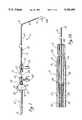
- FIG. 1is a plan view illustrating one form of catheter system constructed in accordance with the teachings of this invention with the everting element everted and the instrument extending from the everting element.
- FIG. 1Ais an enlarged, axial, fragmentary sectional view illustrating a distal region of the everting catheter of FIG. 1 with the everting element everted.
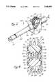
- FIG. 2is a perspective view with parts broken away of one form of controller constructed in accordance with the teachings of this invention.
- FIG. 3is a sectional view taken generally along line 3--3 of FIG. 2 and also illustrating a portion of the inner catheter.
- FIG. 7is a plan view of a non-everting catheter system constructed in accordance with the teachings of this invention.
- FIG. 9is a perspective view illustrating a prior art construction used in insert injection molding to seal off an annular area of a delicate tube to allow high pressure plastic to be molded around it.
- FIG. 10is a side elevational view partially in section of another embodiment of this invention.
- FIG. 11is an enlarged sectional view taken generally along line 11--11 of FIG. 10 with the instrument removed.
- FIG. 12is an enlarged fragmentary sectional view taken on a radial plane and illustrating the preferred configuration of the peripheral surfaces of the drive wheel and secondary wheel with the instrument removed.
- FIG. 1shows an everting catheter system 11 which is particularly adapted for accessing the fallopian tubes; however, it should be understood that the features of this invention are also applicable to catheter systems adapted for other purposes.
- the catheter system 11generally comprises an outer catheter 13, and inner catheter 15, an everting element 17 (FIG. 1A) and an elongated instrument 19.
- the outer catheter 13includes an elongated, flexible catheter body 21 and an outer catheter fitting 23 coupled to the proximal end of the catheter body 21.
- the outer catheter 13has an outer catheter lumen 25 (FIG. 1A) which extends from a proximal opening 27, which is provided by the outer catheter fitting 23, to a distal opening 29 (FIG. 1A) which, in this embodiment, is at the distal end of the catheter body 21.
- the catheter body 21may have multiple lumens, if desired, and the distal opening 29 need not be at the distal end of the catheter body.
- the gatheter body 21has a distal end portion 31 which, in its unstressed condition, may be straight or of any other shape designed to best gain access to a desired region of the body. As shown in FIG. 1, the distal end portion 31 is curved and forms a portion of a circular arc in the unstressed condition, and this facilitates access to the ostia of the fallopian tubes. However, the shape of the distal end portion 31 forms no part of this invention, and the distal end portion is shown for convenience in FIG. 1A as linear.
- the outer catheter 13may be of conventional construction, and the catheter body 21 may be constructed of a flexible, biocompatible polymeric material.
- the outer catheter fitting 23has an injection leg 33 through which an inflation media can be supplied to the outer catheter lumen 25 to control the inversion and eversion of the everting element 17 in a known manner.
- the inner catheter 15is extendible through the proximal opening 27 of the outer catheter 13 and is movable longitudinally in the outer catheter lumen 25.
- the inner catheter 15also includes a catheter body 35 and an inner catheter fitting 37 coupled to the proximal end of the catheter body 35.
- the inner catheter 15has an inner catheter lumen 39 (FIG. 1A) which extends between a proximal opening 41 (FIG. 3) provided by one leg of the inner catheter fitting 37 and a distal opening 43 (FIG. 1A) at the distal end 44 of the catheter body 35.
- the catheter body 35may be flexible or rigid depending upon the nature and purpose of the catheter system 11. However, in this embodiment, a distal region of the catheter body 35 is flexible such that the portion of the catheter body 35 that is within the distal end portion 31 in all positions of the inner catheter 15 relative to the outer catheter 13 is flexible.
- the instrument 19is elongated and flexible.
- the instrument 19is introduced to the inner catheter lumen 39 through the proximal opening 41 and can be moved both proximally and distally relative to the inner catheter 15 independently of the inner catheter.
- the instrument 19terminates distally in a distal end 51 (FIG. 1A).
- the instrument 19is an endoscope for examination of the fallopian tubes.
- the instrumentmay be virtually any elongated, flexible instrument for medical purposes, such as a guidewire or other instrument for either visualizing or carrying out a procedure on an interior region of the body of a patient.
- the catheter system 11 as described to this point in the Description of the Preferred Embodimentmay be conventional. However, the catheter system 11 departs from conventional systems in providing a controller 53 (FIG. 1) coupled to the inner catheter 15 for moving the inner catheter in the outer catheter lumen 25 and instrument 19 in the inner catheter lumen 39 relative to the inner catheter.
- a controller 53FIG. 1
- the handle section 63includes an elongated tube 71 and a tubular connector 73 which receives and is affixed to the proximal end of the tube 71.
- the connector 73has an annular groove 75.
- the grooves 75 and 69are received within openings in the drive section 61 to mount the drive section 61 and the handle section 63 for rotational movement about the axis of the passage 57 relative to the mounting section 59 as described more specifically below.
- the drive section 61is located between the mounting section 59 and the handle section 63 and has an opening 77.
- the wheels 81 and 83are rotatably mounted on the drive section 61, and for that purpose, the drive section has opposite side walls 85 (FIGS. 4-6) joined by end walls 87 (FIGS. 2 and 3) and a transverse wall 89 (FIGS. 4-6).
- the drive section 61forms a container with the opening 77 being generally opposite the transverse wall 89.
- the drive section 61can be a one-piece member, in this embodiment, it comprises two molded half sections 90 (FIGS. 5 and 6) suitably adhered together.
- the wheels 81 and 83can be configured in different ways, in this embodiment, they are identical, and each of them is of one-piece integral construction and includes a central drive disc 95 having a peripheral surface 97 and outer discs 99 having gear teeth 101 on their peripheral surfaces. With the wheels 81 and 83 rotatably mounted within the drive section 61 of the housing 55, the peripheral surfaces 97 are in generally confronting relationship and adapted to receive the instrument 19 therebetween so that, upon rotation of the drive wheel 81, the instrument 19 can be moved longitudinally in the passage 57 of the housing.
- the gear teeth 101 of the drive wheel 81drivingly engage the gear teeth 101 of the secondary wheel 83 so that there is a positive drive connection between these two wheels, and slippage between these wheels is, therefore, prevented.
- the controller 53may be constructed so that the secondary wheel 83 can be directly manually driven.
- the handle section 63 of the housing 55extends proximally of the region or portion of the drive wheel 81 which is exposed through the opening 77 to conveniently position the handle section for manual grasping of the controller 53 and the exposed region of the drive wheel for being manually driven by the thumb of the operator.
- the wheels 81 and 83can be constructed of various different hard and soft materials, and it is not necessary that they both be constructed of the same material.
- the wheels 81 and 83may be constructed of a metal, they may also be constructed of soft material, such as a soft rubber or a relatively hard polymeric material, such as hard polyurethane. If desired, one or both of the wheels 81 and 83 may have an outer, relatively softer, jacket.
- each of the wheels 81 and 83is of one-piece integral construction and is constructed of a relatively hard polymeric material to provide a strong positive driving connection between the interengaging teeth 101.
- the instrument 19is an endoscope of the type having a distal end portion or distal region 105 (FIG. 1) which contains relatively delicate optics and which is of smaller cross-sectional area than a proximal region of the instrument located proximally of a location 107 (FIG. 1) on the instrument.
- the two grooves 103are sized to slidably receive the distal end portion 105 containing the delicate optics without compressively loading the distal end portion. It is not until the location 107 of the instrument 19 is located at the grooves 103 that the grooves begin to compressively load the instrument to form a driving connection therewith. In this manner, the instrument 19 can be more quickly advanced through the controller 53 up to the location 107 without turning of the wheels 81 and 83 and without risking damage to the optics in the distal end portion 105.
- the housing 55is constructed so that the drive section 61 and the handle section 63 are rotatable as a unit about the axis of the passage 57 relative to the mounting section 59.
- the connector 73has a head 109 (FIGS. 3 and 5) within the drive section 61.
- the head 109has lateral edges 111 (FIG. 5) which engage the opposite side walls 85, respectively, of the drive section 61 to prevent rotation of the connector 73 and the entire handle section 63 about the axis of the passage 57 relative to the drive section 61.
- the controller 53can be coupled to the inner catheter 15 in various different ways, such as by constructing the housing 55 and the inner catheter fitting 37 of one-piece integral construction, in this embodiment, the housing 55 is a separate element, and the controller 53 is releasably coupled to the inner catheter 15.
- the inner catheter fitting 37has a leg 113 with external threads which is threaded into the mounting section 59.
- a seal 115is compressively loaded between the distal end of the projection 65 and an adjacent region of the leg 113 to provide a seal between the fitting 37 and the controller 53. The seal 115 is compressed sufficiently to provide a seal around the instrument 19.
- This inventionprovides means for guiding the instrument 19 to the wheels 81 and 83 and into the grooves 103.
- this meansmay take different forms, in the illustrated embodiment, it includes a pair of tabs 117 (FIGS. 2-5) which extend distally into the drive section 61 and into annular spaces 119 (FIGS. 2 and 4), respectively, between the discs 95 and 99.
- the alignment tabs 117extend at least to a location at which the wheels 81 and 83 are tangent to each other as shown in FIG. 3. Consequently, the tabs 117 serve to guide the instrument 19 into the grooves 103 when the instrument is being initially threaded into the controller 53.
- the outer catheter 13 with the everting element 17 in the inverted positionis inserted into the body of the patient to the desired region.
- the instrument 19is then inserted through the passage 57 and the grooves 103 of the controller and through the inner catheter fitting 37 into the inner catheter lumen 39. If the instrument 19 is of the type described above having the distal end portion 105 of reduced diameter, it may be slid through the grooves 103 without rotation of the wheels 81 and 83. However, when the location 107 reaches the wheels 81 and 83, the instrument 19 can be advanced or moved distally only by rotating the drive wheel 81. In this position, the instrument 19 is frictionally gripped between the drive wheel 81 and the secondary wheel 83 so that rotation of the drive wheel 81 moves the instrument 19 longitudinally.
- the everting element 17When the everting element 17 is everted, it grips the instrument 19 and pulls it distally. However, when it is desired to move the instrument 19 relative to the everting element 17, the controller 53 can be used. Movement of the instrument 19 longitudinally and longitudinal movement of the inner catheter 15 can be easily accomplished in a one-handed operation. Thus, the physician merely grasps the handle section 63 with his thumb contacting the drive wheel 81 and, by so doing, his thumb can drive the drive wheel and instrument, and his hand can move the inner catheter. These movements of the instrument 19 can be coordinated with the eversion and inversion of the everting element 17 as desired.
- FIG. 7shows a catheter system 11a which is identical to the catheter system 11 in all respects not shown or described herein. Portions of the catheter system 11a corresponding to portions of the catheter system 11 are designated by corresponding reference numerals followed by the letter "a.”
- the catheter system 11ais identical to the catheter system 11, except that the catheter is of the non-everting type.
- the catheter system 11ahas no everting element and may be considered as comprising only the inner catheter 15a and the controller 53a.
- the catheter 15ais not an inner catheter but rather the only catheter of the system.
- the controller 53ais identical to the controller 53 and controls the longitudinal and rotational position of the instrument 19a within the catheter 15a.
- FIG. 8shows a catheter system 11b which is identical to the catheter system 11 in all respects not shown or described herein. Portions of the catheter system 11b corresponding to portions of the catheter system 11 are designated by corresponding reference numerals followed by the letter "b.”
- the only difference between the catheter systems 11 and 11bis that the latter provides interlocking projections or gear teeth 131 and recesses 133 on the instrument 19b and the drive wheel 81b and the secondary wheel 83b.
- Thisprovides a positive driving relationship between the driving device 79b and, in particular, the wheels 81b and 83b, and the instrument 19b.
- the teeth 131 and the recesses 133 of the wheels 81b and 83bare located on the peripheral surfaces 97b, and they cooperate with the teeth 131 and recesses 133 of the instrument 19b to form a gear drive between these members.
- the teeth 131 and recesses 133may be located proximally of the distal end 51 of the instrument 19b and along a length of the instrument which includes a region of the instrument which is at the driving device 79b when the distal end of the instrument is adjacent the distal opening 29.
- the teeth 131may be proximally of the location 107 (FIG. 1) on the instrument 19b and will not hamper sliding movement of the instrument through the controller 53b up to the location 107.
- the positive drive connection between the instrument and the wheels 81b and 83bis obtained where that driving connection is desirable. By providing the positive drive connection, slippage between the drive wheel 81b and the instrument 19b is eliminated, and the physician is assured of having precise control over the longitudinal movements of the instrument.
- FIGS. 10-12show a controller 53c which is identical to the controller 53 of FIGS. 1-6 in all respects not shown or described herein. Portions of the controller 53c corresponding to portions of the controller 53 are designed by corresponding reference numerals followed by the letter "c".
- the controller 53cmay be used in the everting catheter system 11 of FIG. 1 or with a non-everting catheter. Although the controller 53c can be used with virtually any elongated flexible instrument 19c, it is particularly adapted for use with instruments which must be controllable without slippage relative to the controller 53c when the instrument encounters resistance to movement and which may be damaged or provide a distorted signal if the compressive forces on the instrument are greater than a predetermined magnitude.
- the primary difference between the controllers 53 and 53cis the configuration of the peripheral surfaces 97c.
- Each of the peripheral surfaces 97chas an instrument groove portion or groove 103c (FIG. 12).
- the peripheral surfaces 97care in generally confronting relationship such that the instrument groove portions 103c are aligned and cooperate to provide an instrument groove 201 which is preferably generally circular in cross section and which is sized and adapted to receive the elongated medical instrument 19c.
- each of the wheelshas a circumferential projection 203 and a circumferential recess 205.
- the projections 203 and the recesses 205are annular.
- Each of the projections 203has sides 207 which slope toward each other as the sides extend radially outwardly and an end surface 209 which is curved in radial cross section (FIG. 12) and which joins the sides 207.
- each of the recesses 205has sides 211 which slope toward each other as they extend radially inwardly and which are joined by an end surface 213 which is curved in radial cross section (FIG. 12).
- the sides 207 and 211are flat as viewed in radial cross section. With this arrangement, a portion of the adjacent sides 207 of the projections 203 form regions of the associated groove portion 103c and of the instrument groove 201. Also, each of the peripheral surfaces 97c defines a narrow annular web 215 between the instrument groove portion 103c and the recess 205 of the associated wheel 81c and 83c.
- each of the projections 203is received within the recess 205 of the opposing wheel.
- the projections 203 and the recesses 205are complementary in size and configuration such that each of the recesses properly receive the confronting projection to define an aligned position which is maintained as the wheels 81c and 83c rotate.
- the instrument groove portions 103cprovide the instrument groove 201 of the desired size and configuration.
- the projections 203 and the recess 205accurately position the instrument groove portions 103c axially, i.e. horizontally as viewed in FIGS. 11 and 12, and the instrument groove portions 103c are not shifted axially relative to each other so that a properly configured instrument groove 201 is provided.
- the shafts or axles 91cwhich are rotatably mounted in the bearings 93c, may be positioned so as to mount the wheels to preload the projections 203 against the surfaces of the recesses 205.
- the gear teeth 101c in this embodimentare located axially outwardly of the projections 203, and as shown in FIG. 12, the instrument groove 201 is between the projections 203.
- FIG. 9shows a prior art construction that is used in insert injection molding to prevent crushing of a tube 221 by blocks 223 and 225 which receive the tube.
- the block 223has a recess 227 and the block 225 has a projection 229 with a concave surface 231 and the recess receives the projection.
- the concave surface 231cooperates with the recess 227 to define a groove for receiving the tube 221 without crushing of the tube.
- the axles 91care preferably constructed of metal, such as steel.
- the bearings 93clike the bearings 93, are constructed of a suitable hard polymeric material such as polycarbonate.
- the steel axles 91c on the polycarbonate bearings 93cprovide a low coefficient of friction.
- the peripheral surfaces 97c, and preferably the wheels 81c and 83c,are constructed of a resilient deformable material, such as a suitable polymeric material.
- a resilient deformable materialsuch as a suitable polymeric material.
- a preferred polymeric materialis Kraton rubber which is a polymer of the styrene-ethylene/butylene-styrene type.
- a preferred Kraton rubberis Kraton G-7820, which has a Shore A hardness of 91.
- Kraton rubberis available from Shell Chemical Company.
- the resilient deformable materialshould also have a relatively high coefficient of friction.
- the tabs 117 of the controller 53are eliminated.
- the head 109cis generally conical to provide a nose 235 which extends between the wheels 81c and 83c (FIG. 10) to a location closely adjacent the regions where the peripheral surfaces 97c engage.
- the head 109chas a passage section 237, which exertts a portion of the passage 57c.
- the passage section 237is of reduced diameter so that the instrument 19c can slide through it with minimal clearance and be guided accurately to the instrument groove 201 (FIG. 12).
- the instrument 19cmay be identical to the instrument 19.
- the cross section of the instrument groove 201is large enough to slidably receive the distal region 105 (FIG. 1) of the instrument and is smaller than the cross section of the proximal region, i.e. the region of the instrument proximally of the location 107 (FIG. 1). This enables the distal region of the instrument 19c to be more flexible than the proximal region, prevents the wheels 81c and 83c from compressively loading any optics with the distal region of the instrument and enables rapid insertion of the distal region through the instrument groove 201.
- the diameter of the instrument groove 201may be about 0.023 inch and the diameters of the proximal and distal regions of the instrument may be, for example, about 0.0315 inch and 0.020 inch, respectively.
- the proximal region of the instrument 19cmay be about 14 inches in length, and the controller may be used primarily to move the distal-most 10 inches of the proximal region of the instrument.
- the controller 53ccan be employed with the instrument 19c in much the same manner as described above in connection with the controller 53 and the instrument 19.
- the resilient deformable peripheral surfaces 97c of the wheels 81c and 83ccan be deformed to permit the cross section of the instrument groove 201 to be expanded sufficiently to receive the proximal region of the instrument 19c, i.e. the region of the instrument proximally of the location 107 (FIG. 1) which has a diameter larger than the diameter of the unstressed instrument grove 201.
- the peripheral surfaces 97cthe peripheral surfaces tightly grip the instrument so as to tend to prevent slippage without applying compressive loads to the instrument that would damage the instrument or distort the signal provided by it.
- the deformation of the peripheral surfaces 97cprevents undue forces between the shafts 91c and the bearings 93c which would make the drive wheel 81c difficult to drive manually with thumb pressure from the operator.
Landscapes
- Health & Medical Sciences (AREA)
- Life Sciences & Earth Sciences (AREA)
- Biophysics (AREA)
- Pulmonology (AREA)
- Engineering & Computer Science (AREA)
- Anesthesiology (AREA)
- Biomedical Technology (AREA)
- Heart & Thoracic Surgery (AREA)
- Hematology (AREA)
- Animal Behavior & Ethology (AREA)
- General Health & Medical Sciences (AREA)
- Public Health (AREA)
- Veterinary Medicine (AREA)
- Media Introduction/Drainage Providing Device (AREA)
Abstract
Description
Claims (28)
Priority Applications (3)
| Application Number | Priority Date | Filing Date | Title |
|---|---|---|---|
| US08/008,774US5346498A (en) | 1991-11-06 | 1993-01-25 | Controller for manipulation of instruments within a catheter |
| PCT/US1994/000374WO1994016762A1 (en) | 1993-01-25 | 1994-01-11 | Controller for manipulating instruments within a catheter |
| AU60252/94AAU6025294A (en) | 1993-01-25 | 1994-01-11 | Controller for manipulating instruments within a catheter |
Applications Claiming Priority (2)
| Application Number | Priority Date | Filing Date | Title |
|---|---|---|---|
| US07/788,338US5389100A (en) | 1991-11-06 | 1991-11-06 | Controller for manipulation of instruments within a catheter |
| US08/008,774US5346498A (en) | 1991-11-06 | 1993-01-25 | Controller for manipulation of instruments within a catheter |
Related Parent Applications (1)
| Application Number | Title | Priority Date | Filing Date |
|---|---|---|---|
| US07/788,338Continuation-In-PartUS5389100A (en) | 1991-11-06 | 1991-11-06 | Controller for manipulation of instruments within a catheter |
Publications (1)
| Publication Number | Publication Date |
|---|---|
| US5346498Atrue US5346498A (en) | 1994-09-13 |
Family
ID=21733592
Family Applications (1)
| Application Number | Title | Priority Date | Filing Date |
|---|---|---|---|
| US08/008,774Expired - Fee RelatedUS5346498A (en) | 1991-11-06 | 1993-01-25 | Controller for manipulation of instruments within a catheter |
Country Status (3)
| Country | Link |
|---|---|
| US (1) | US5346498A (en) |
| AU (1) | AU6025294A (en) |
| WO (1) | WO1994016762A1 (en) |
Cited By (153)
| Publication number | Priority date | Publication date | Assignee | Title |
|---|---|---|---|---|
| US5492131A (en)* | 1994-09-06 | 1996-02-20 | Guided Medical Systems, Inc. | Servo-catheter |
| US5630797A (en)* | 1995-01-17 | 1997-05-20 | Imagyn Medical, Inc. | Everting catheter system and method of utilizing the same |
| US5643292A (en)* | 1995-01-10 | 1997-07-01 | Applied Medical Resources Corporation | Percutaneous suturing device |
| US5707376A (en)* | 1992-08-06 | 1998-01-13 | William Cook Europe A/S | Stent introducer and method of use |
| US5827241A (en)* | 1995-06-07 | 1998-10-27 | C. R. Bard, Inc. | Rapid exchange guidewire mechanism |
| US5868755A (en)* | 1997-01-16 | 1999-02-09 | Atrion Medical Products, Inc. | Sheath retractor mechanism and method |
| US6039721A (en)* | 1996-07-24 | 2000-03-21 | Cordis Corporation | Method and catheter system for delivering medication with an everting balloon catheter |
| WO2000018463A1 (en)* | 1998-09-25 | 2000-04-06 | Boston Scientific Limited | Imaging core loading tool |
| US6090063A (en)* | 1995-12-01 | 2000-07-18 | C. R. Bard, Inc. | Device, system and method for implantation of filaments and particles in the body |
| WO2001013832A1 (en) | 1999-08-23 | 2001-03-01 | Conceptus, Inc. | Insertion/deployment catheter system for intrafallopian contraception |
| US6231564B1 (en) | 1995-09-29 | 2001-05-15 | Medtronic Ave, Inc. | Storable guidewire system |
| US6358199B1 (en)* | 1998-05-06 | 2002-03-19 | Stm Medizintechnik Starnberg Gmbh | Drive means for flexible eversion tube system |
| US6394976B1 (en) | 2000-01-31 | 2002-05-28 | Intraluminal Therapeutics, Inc. | Catheter for controlling the advancement of a guide wire |
| US20020177789A1 (en)* | 2001-05-06 | 2002-11-28 | Ferry Steven J. | System and methods for advancing a catheter |
| US6514261B1 (en) | 1998-09-30 | 2003-02-04 | Impra, Inc. | Delivery mechanism for implantable stent |
| US20030105508A1 (en)* | 2000-03-21 | 2003-06-05 | Johnson Kirk L. | Everting balloon stent delivery system having tapered leading edge |
| US20040087966A1 (en)* | 2002-01-24 | 2004-05-06 | Incumed Inc. | Guidewire reel and related methods |
| US20040163650A1 (en)* | 1999-08-23 | 2004-08-26 | Conceptus, Inc. | Deployment actuation system for intrafallopian contraception |
| US20040181239A1 (en)* | 2001-04-30 | 2004-09-16 | Jurgen Dorn | Self-expanding stent delivery device |
| US20040186511A1 (en)* | 2003-03-20 | 2004-09-23 | Adam Stephens | Control handle for intraluminal devices |
| US20050027345A1 (en)* | 2003-02-14 | 2005-02-03 | Steven Horan | Stent delivery and deployment system |
| US20050060016A1 (en)* | 2003-09-12 | 2005-03-17 | Wu Patrick P. | Delivery system for medical devices |
| US20050061329A1 (en)* | 2003-09-18 | 2005-03-24 | Conceptus, Inc. | Catheter for intrafallopian contraceptive delivery |
| US20050090890A1 (en)* | 2003-09-12 | 2005-04-28 | Wu Patrick P. | Delivery system for medical devices |
| US20050119522A1 (en)* | 2003-11-28 | 2005-06-02 | Olympus Corporation | Endoscope treatment tool insertion-extraction system |
| US20050171568A1 (en)* | 2004-01-30 | 2005-08-04 | Niall Duffy | Catheter and guidewire exchange system with improved catheter design |
| US20050209707A1 (en)* | 1998-04-10 | 2005-09-22 | Phillips Van L | Active shock module prosthesis |
| US20050245847A1 (en)* | 2004-04-30 | 2005-11-03 | Cook, Inc. | Wire guide apparatus |
| US20050250989A1 (en)* | 2004-02-03 | 2005-11-10 | Keita Suzuki | Endoscopic therapeutic instrument, endoscope, and endoscopic therapeutic system |
| US20050288551A1 (en)* | 2004-04-28 | 2005-12-29 | Ams Research Corporation | Endoscopic delivery of medical devices |
| US20060025721A1 (en)* | 2004-07-30 | 2006-02-02 | Niall Duffy | Catheter and guidewire exchange system with improved catheter design |
| WO2005117688A3 (en)* | 2004-06-01 | 2006-03-09 | Stereotaxis Inc | Systems and methods for medical device advancement and rotation |
| US20060211953A1 (en)* | 2004-10-29 | 2006-09-21 | Zannis Anthony D | Coordinate instrument set |
| US20060224162A1 (en)* | 2004-04-15 | 2006-10-05 | Olympus Corporation | Endoscopic treatment system |
| US20060224176A1 (en)* | 2005-03-31 | 2006-10-05 | Fung Gregory W | Guide wire locking mechanism for rapid exchange and other catheter systems |
| US20060247523A1 (en)* | 1996-09-13 | 2006-11-02 | Scimed Life Systems, Inc. | Guide wire insertion and re-insertion tools and methods of use |
| US7131980B1 (en)* | 2001-01-18 | 2006-11-07 | Dvl Acquisitions Sub, Inc. | Surgical suturing instrument and method of use |
| US20070055340A1 (en)* | 2005-09-02 | 2007-03-08 | Medtronic Vascular, Inc., A Delaware Corporation | Stent delivery system with multiple evenly spaced pullwires |
| US20070179510A1 (en)* | 2006-02-02 | 2007-08-02 | Arthrotek, Inc. | Method and apparatus for passing a flexible strand |
| US20070219617A1 (en)* | 2006-03-17 | 2007-09-20 | Sean Saint | Handle for Long Self Expanding Stent |
| US20080045859A1 (en)* | 2006-08-19 | 2008-02-21 | Fritsch Michael H | Devices and Methods for In-Vivo Pathology Diagnosis |
| US20080045892A1 (en)* | 2001-05-06 | 2008-02-21 | Ferry Steven J | System and Methods for Advancing a Catheter |
| US20080103358A1 (en)* | 2004-03-23 | 2008-05-01 | Keita Suzuki | Endoscope system |
| US20080200756A1 (en)* | 2007-02-20 | 2008-08-21 | Olympus Medical Systems Corporation | Medical system and endoscope system |
| USD576725S1 (en) | 2007-06-20 | 2008-09-09 | Abbot Laboratories, Inc. | Medical device delivery handle |
| USD578644S1 (en) | 2007-06-20 | 2008-10-14 | Abbott Laboratories | Medical device delivery handle |
| USD578645S1 (en) | 2007-06-20 | 2008-10-14 | Abbott Laboratories | Medical device delivery handle |
| USD578643S1 (en) | 2007-06-20 | 2008-10-14 | Abbott Laboratories | Medical device delivery handle |
| US20090105639A1 (en)* | 2001-02-15 | 2009-04-23 | Hansen Medical, Inc. | Catheter driver system |
| US20090105713A1 (en)* | 2007-10-09 | 2009-04-23 | William Cook, Europe Aps | Deployment handle for an implant deployment device |
| US20090210046A1 (en)* | 2008-02-20 | 2009-08-20 | Abbott Laboratories | Handle assembly for a delivery system |
| US20090270969A1 (en)* | 2008-04-26 | 2009-10-29 | Biotronik Vi Patent Ag | Delivery system having a release mechanism for releasing an object carried by a catheter as well as a release mechanism of a delivery system |
| US20100036472A1 (en)* | 2008-08-08 | 2010-02-11 | Abbott Cardiovascular Systems Inc. | Delivery system with variable delivery rate for deploying a medical device |
| US7727255B2 (en) | 2001-08-14 | 2010-06-01 | Applied Medical Resources Corporation | Access sealing apparatus and method |
| US20100241141A1 (en)* | 2007-05-08 | 2010-09-23 | Lee Heeyoung | Tools for fiber reinforced anti-compressive adherent suture method |
| US20110028941A1 (en)* | 2008-04-10 | 2011-02-03 | Yoshitaka Nagano | Linear object manipulation control device for controlling manipulation of linear object by operator |
| US7921848B2 (en) | 1995-06-07 | 2011-04-12 | Conceptus, Inc. | Contraceptive transcervical fallopian tube occlusion devices and methods |
| US7935141B2 (en) | 2005-08-17 | 2011-05-03 | C. R. Bard, Inc. | Variable speed stent delivery system |
| US7993329B2 (en) | 2002-08-13 | 2011-08-09 | Cook Medical Technologies Llc | ERCP catheter with a removable handle for lithotriptor compatible basket |
| US8062344B2 (en) | 2001-04-30 | 2011-11-22 | Angiomed Gmbh & Co. Medizintechnik Kg | Variable speed self-expanding stent delivery system and luer locking connector |
| US8066007B2 (en) | 1995-06-07 | 2011-11-29 | Conceptus, Inc. | Contraceptive transcervical fallopian tube occlusion devices and their delivery |
| US20120035596A1 (en)* | 2010-08-04 | 2012-02-09 | Tegg Troy T | Disposable Drive Interface for Longitudinal Movement of an Elongate Medical Device |
| US20120165915A1 (en)* | 2010-12-22 | 2012-06-28 | Cook Incorporated (d/b/a Cook Critical Care Incorporated) | Emergency vascular repair prosthesis deployment system |
| US20120259355A1 (en)* | 2011-04-08 | 2012-10-11 | Kyphon Sarl | Retractable inflatable bone tamp |
| US8343041B2 (en) | 2008-05-19 | 2013-01-01 | Boston Scientific Scimed, Inc. | Integrated locking device with passive sealing |
| US20130035548A1 (en)* | 2010-03-22 | 2013-02-07 | Tufts Medical Center, Inc. | Fiber optic intubating device |
| US8388521B2 (en) | 2008-05-19 | 2013-03-05 | Boston Scientific Scimed, Inc. | Integrated locking device with active sealing |
| US8414505B1 (en)* | 2001-02-15 | 2013-04-09 | Hansen Medical, Inc. | Catheter driver system |
| US8500789B2 (en) | 2007-07-11 | 2013-08-06 | C. R. Bard, Inc. | Device for catheter sheath retraction |
| US20130274657A1 (en)* | 2010-09-17 | 2013-10-17 | Corindus, Inc. | Wheel for robotic catheter system drive mechanism |
| US8652193B2 (en) | 2005-05-09 | 2014-02-18 | Angiomed Gmbh & Co. Medizintechnik Kg | Implant delivery device |
| US20140100552A1 (en)* | 2012-10-02 | 2014-04-10 | The Queen's Medical Center | Vascular access systems having a guidewire anti-migration feature |
| US8703034B2 (en) | 2001-08-14 | 2014-04-22 | Applied Medical Resources Corporation | Method of making a tack-free gel |
| US8808346B2 (en) | 2006-01-13 | 2014-08-19 | C. R. Bard, Inc. | Stent delivery system |
| US20140276648A1 (en)* | 2013-03-14 | 2014-09-18 | Valtech Cardio, Ltd. | Guidewire feeder |
| US20140277334A1 (en)* | 2013-03-14 | 2014-09-18 | Hansen Medical, Inc. | Active drives for robotic catheter manipulators |
| US20150119860A1 (en)* | 2013-10-24 | 2015-04-30 | Kimberly-Clark Worldwide, Inc. | Catheter Advancement Device |
| US9078779B2 (en) | 2006-08-07 | 2015-07-14 | C. R. Bard, Inc. | Hand-held actuator device |
| US20150272733A1 (en)* | 2008-05-09 | 2015-10-01 | Edwards Lifesciences Corporation | Low profile delivery system for transcatheter heart valve |
| US20150306358A1 (en)* | 2014-04-24 | 2015-10-29 | Medtronic Vascular Galway | Control module for delivery systems |
| US20150352318A1 (en)* | 2013-02-27 | 2015-12-10 | The George Washington University | Ultrasound assisted catheter placement system |
| US9326822B2 (en) | 2013-03-14 | 2016-05-03 | Hansen Medical, Inc. | Active drives for robotic catheter manipulators |
| US20170065415A1 (en)* | 2015-09-04 | 2017-03-09 | Edwards Lifesciences Corporation | Delivery system for prosthetic heart valve |
| CN106821511A (en)* | 2017-03-09 | 2017-06-13 | 广州永士达医疗科技有限责任公司 | A kind of OCT medical catheters pumpback device |
| US9724192B2 (en) | 2011-11-08 | 2017-08-08 | Valtech Cardio, Ltd. | Controlled steering functionality for implant-delivery tool |
| US9730793B2 (en) | 2012-12-06 | 2017-08-15 | Valtech Cardio, Ltd. | Techniques for guide-wire based advancement of a tool |
| US9775709B2 (en) | 2011-11-04 | 2017-10-03 | Valtech Cardio, Ltd. | Implant having multiple adjustable mechanisms |
| US9801745B2 (en) | 2010-10-21 | 2017-10-31 | C.R. Bard, Inc. | System to deliver a bodily implant |
| US9872769B2 (en) | 2006-12-05 | 2018-01-23 | Valtech Cardio, Ltd. | Implantation of repair devices in the heart |
| US9937042B2 (en) | 2009-05-07 | 2018-04-10 | Valtech Cardio, Ltd. | Multiple anchor delivery tool |
| US9949828B2 (en) | 2012-10-23 | 2018-04-24 | Valtech Cardio, Ltd. | Controlled steering functionality for implant-delivery tool |
| US9968454B2 (en) | 2009-10-29 | 2018-05-15 | Valtech Cardio, Ltd. | Techniques for guide-wire based advancement of artificial chordae |
| US9968452B2 (en) | 2009-05-04 | 2018-05-15 | Valtech Cardio, Ltd. | Annuloplasty ring delivery cathethers |
| US10098737B2 (en) | 2009-10-29 | 2018-10-16 | Valtech Cardio, Ltd. | Tissue anchor for annuloplasty device |
| US10143826B2 (en) | 2014-10-31 | 2018-12-04 | SonoStik LLC | Wire introduction device for introducing guide wire |
| WO2019010244A1 (en) | 2017-07-03 | 2019-01-10 | Crossbay Medical, Inc. | Apparatus and method for everting catheter with alignment and compliant pressurization |
| US10195030B2 (en) | 2014-10-14 | 2019-02-05 | Valtech Cardio, Ltd. | Leaflet-restraining techniques |
| US10226342B2 (en) | 2016-07-08 | 2019-03-12 | Valtech Cardio, Ltd. | Adjustable annuloplasty device with alternating peaks and troughs |
| US10265170B2 (en) | 2013-12-26 | 2019-04-23 | Valtech Cardio, Ltd. | Implantation of flexible implant |
| US10299793B2 (en) | 2013-10-23 | 2019-05-28 | Valtech Cardio, Ltd. | Anchor magazine |
| US10350068B2 (en) | 2009-02-17 | 2019-07-16 | Valtech Cardio, Ltd. | Actively-engageable movement-restriction mechanism for use with an annuloplasty structure |
| US10357366B2 (en) | 2006-12-05 | 2019-07-23 | Valtech Cardio, Ltd. | Implantation of repair devices in the heart |
| US10376266B2 (en) | 2012-10-23 | 2019-08-13 | Valtech Cardio, Ltd. | Percutaneous tissue anchor techniques |
| US10376672B2 (en) | 2013-03-15 | 2019-08-13 | Auris Health, Inc. | Catheter insertion system and method of fabrication |
| US10470882B2 (en) | 2008-12-22 | 2019-11-12 | Valtech Cardio, Ltd. | Closure element for use with annuloplasty structure |
| US10492909B2 (en) | 2009-12-02 | 2019-12-03 | Valtech Cardio, Ltd. | Tool for actuating an adjusting mechanism |
| US10548729B2 (en) | 2009-05-04 | 2020-02-04 | Valtech Cardio, Ltd. | Deployment techniques for annuloplasty ring and over-wire rotation tool |
| US10561498B2 (en) | 2005-03-17 | 2020-02-18 | Valtech Cardio, Ltd. | Mitral valve treatment techniques |
| US10576248B2 (en) | 2018-07-23 | 2020-03-03 | Crossbay Medical, Inc. | Apparatus and method for everting catheter for uterine access for biopsy and cytology |
| US10682232B2 (en) | 2013-03-15 | 2020-06-16 | Edwards Lifesciences Corporation | Translation catheters, systems, and methods of use thereof |
| US10695046B2 (en) | 2005-07-05 | 2020-06-30 | Edwards Lifesciences Corporation | Tissue anchor and anchoring system |
| US10702274B2 (en) | 2016-05-26 | 2020-07-07 | Edwards Lifesciences Corporation | Method and system for closing left atrial appendage |
| US10751182B2 (en) | 2015-12-30 | 2020-08-25 | Edwards Lifesciences Corporation | System and method for reshaping right heart |
| US10765514B2 (en) | 2015-04-30 | 2020-09-08 | Valtech Cardio, Ltd. | Annuloplasty technologies |
| US10792112B2 (en) | 2013-03-15 | 2020-10-06 | Auris Health, Inc. | Active drive mechanism with finite range of motion |
| US10792152B2 (en) | 2011-06-23 | 2020-10-06 | Valtech Cardio, Ltd. | Closed band for percutaneous annuloplasty |
| US10828160B2 (en) | 2015-12-30 | 2020-11-10 | Edwards Lifesciences Corporation | System and method for reducing tricuspid regurgitation |
| US10835221B2 (en) | 2017-11-02 | 2020-11-17 | Valtech Cardio, Ltd. | Implant-cinching devices and systems |
| US10856986B2 (en) | 2008-12-22 | 2020-12-08 | Valtech Cardio, Ltd. | Adjustable annuloplasty devices and adjustment mechanisms therefor |
| US10918373B2 (en) | 2013-08-31 | 2021-02-16 | Edwards Lifesciences Corporation | Devices and methods for locating and implanting tissue anchors at mitral valve commissure |
| US10918374B2 (en) | 2013-02-26 | 2021-02-16 | Edwards Lifesciences Corporation | Devices and methods for percutaneous tricuspid valve repair |
| US10925610B2 (en) | 2015-03-05 | 2021-02-23 | Edwards Lifesciences Corporation | Devices for treating paravalvular leakage and methods use thereof |
| US11026822B2 (en) | 2006-01-13 | 2021-06-08 | C. R. Bard, Inc. | Stent delivery system |
| US11045627B2 (en) | 2017-04-18 | 2021-06-29 | Edwards Lifesciences Corporation | Catheter system with linear actuation control mechanism |
| US11064870B2 (en) | 2017-08-11 | 2021-07-20 | Boston Scientific Limited | Biopsy cap for use with endoscope |
| US11123191B2 (en) | 2018-07-12 | 2021-09-21 | Valtech Cardio Ltd. | Annuloplasty systems and locking tools therefor |
| US11135062B2 (en) | 2017-11-20 | 2021-10-05 | Valtech Cardio Ltd. | Cinching of dilated heart muscle |
| US11141308B2 (en) | 2017-08-31 | 2021-10-12 | Crossbay Medical, Inc. | Apparatus and method for everting catheter for IUD delivery and placement in the uterine cavity |
| US11259924B2 (en) | 2006-12-05 | 2022-03-01 | Valtech Cardio Ltd. | Implantation of repair devices in the heart |
| WO2022112768A1 (en)* | 2020-11-30 | 2022-06-02 | King's College London | An eversion robot system and method of operating the eversion robot system |
| US11395648B2 (en) | 2012-09-29 | 2022-07-26 | Edwards Lifesciences Corporation | Plication lock delivery system and method of use thereof |
| US20220252804A1 (en)* | 2021-02-08 | 2022-08-11 | Scholly Fiberoptic Gmbh | Coupling device for light guides |
| US11439464B2 (en)* | 2016-06-28 | 2022-09-13 | Karl PIEPER | Appliance for conveying a catheter, light guide or cable in a controlled manner |
| US20220380169A1 (en)* | 2021-05-28 | 2022-12-01 | Endo Robotics Co., Ltd. | Tubular member moving apparatus |
| US11617863B2 (en)* | 2019-10-19 | 2023-04-04 | Anthony DiCianni | Intravenous catheter and guidewire advancement mechanism |
| US11660191B2 (en) | 2008-03-10 | 2023-05-30 | Edwards Lifesciences Corporation | Method to reduce mitral regurgitation |
| US11660190B2 (en) | 2007-03-13 | 2023-05-30 | Edwards Lifesciences Corporation | Tissue anchors, systems and methods, and devices |
| US11666442B2 (en) | 2018-01-26 | 2023-06-06 | Edwards Lifesciences Innovation (Israel) Ltd. | Techniques for facilitating heart valve tethering and chord replacement |
| US11766327B2 (en) | 2009-05-04 | 2023-09-26 | Edwards Lifesciences Innovation (Israel) Ltd. | Implantation of repair chords in the heart |
| US11779463B2 (en) | 2018-01-24 | 2023-10-10 | Edwards Lifesciences Innovation (Israel) Ltd. | Contraction of an annuloplasty structure |
| US11819411B2 (en) | 2019-10-29 | 2023-11-21 | Edwards Lifesciences Innovation (Israel) Ltd. | Annuloplasty and tissue anchor technologies |
| US11969348B2 (en) | 2011-12-12 | 2024-04-30 | Edwards Lifesciences Corporation | Cardiac valve replacement |
| US12023247B2 (en) | 2020-05-20 | 2024-07-02 | Edwards Lifesciences Corporation | Reducing the diameter of a cardiac valve annulus with independent control over each of the anchors that are launched into the annulus |
| US12035898B2 (en) | 2005-04-22 | 2024-07-16 | Edwards Lifesciences Corporation | Catheter-based tissue remodeling devices and methods |
| US12138165B2 (en) | 2011-06-23 | 2024-11-12 | Edwards Lifesciences Innovation (Israel) Ltd. | Annuloplasty implants |
| US12208006B2 (en) | 2019-09-25 | 2025-01-28 | Edwards Lifesciences Corporation | Constricting a cardiac valve annulus using a cord that has a loop portion and a single second portion |
| US12226096B2 (en) | 2019-05-29 | 2025-02-18 | Edwards Lifesciences Innovation (Israel) Ltd. | Tissue anchor handling systems and methods |
| EP4529935A2 (en) | 2013-11-11 | 2025-04-02 | CrossBay Medical, Inc. | Apparatus for accessing and sealing bodily vessels and cavities |
| EP4566975A1 (en)* | 2023-12-07 | 2025-06-11 | Koninklijke Philips N.V. | Drive roller for advancing and/or retracting a cylindrical object |
| US12364606B2 (en) | 2019-07-23 | 2025-07-22 | Edwards Lifesciences Innovation (Israel) Ltd. | Fluoroscopic visualization of heart valve anatomy |
| US12396718B2 (en) | 2020-06-19 | 2025-08-26 | Edwards Lifesciences Corporation | Self-stopping tissue anchors |
| US12419749B2 (en) | 2019-08-30 | 2025-09-23 | Edwards Lifesciences Innovation (Israel) Ltd. | Anchor channel tip |
| US12440648B2 (en) | 2022-02-25 | 2025-10-14 | Edwards Lifesciences Innovation (Israel) Ltd. | Low-profile steerable catheter |
Families Citing this family (9)
| Publication number | Priority date | Publication date | Assignee | Title |
|---|---|---|---|---|
| AT406227B (en)* | 1997-01-09 | 2000-03-27 | Vujanic Aleksandar Dr | Device for withdrawing a catheter |
| US20060095048A1 (en) | 2004-10-29 | 2006-05-04 | Zannis Anthony D | Method of repairing soft tissue using sizing templates |
| CN103239793A (en)* | 2013-05-17 | 2013-08-14 | 徐州医学院 | Vessel intervention robot guide wire driving box |
| US9974676B2 (en) | 2013-08-09 | 2018-05-22 | Cook Medical Technologies Llc | Wire collection device with geared advantage |
| US9974677B2 (en) | 2013-08-20 | 2018-05-22 | Cook Medical Technologies Llc | Wire collection device for stent delivery system |
| US9974678B2 (en) | 2014-03-10 | 2018-05-22 | Cook Medical Technologies Llc | Wire collection device with varying collection diameter |
| CN104840257B (en)* | 2015-05-22 | 2018-04-13 | 林健泽 | A kind of interposing catheter conveying and recycling guidance robot |
| WO2018053633A1 (en)* | 2016-09-22 | 2018-03-29 | Sunnybrook Health Sciences Centre | Catheter advancement device |
| US11039846B2 (en)* | 2017-04-25 | 2021-06-22 | Biosense Webster (Israel) Ltd. | Guidewire manipulator |
Citations (27)
| Publication number | Priority date | Publication date | Assignee | Title |
|---|---|---|---|---|
| FR450345A (en)* | 1912-11-08 | 1913-03-21 | Steenbrugghe Et Breton Soc Van | Mechanical propellant for ureteral catheters in cystoscopic ureters catheterization |
| US1087845A (en)* | 1913-07-16 | 1914-02-17 | James H Stevens | Salvarsan-needle. |
| US1901731A (en)* | 1932-05-09 | 1933-03-14 | Buerger Leo | Cystoscope and the like |
| US3552384A (en)* | 1967-07-03 | 1971-01-05 | American Hospital Supply Corp | Controllable tip guide body and catheter |
| US3835854A (en)* | 1970-02-27 | 1974-09-17 | Jewett Ashley Holding Corp | Catheter advancing device with nip rollers |
| DE2406823A1 (en)* | 1974-02-13 | 1975-08-14 | Peter Udo | Catheterisation of straight or sinuous tubular body organs - using double tube, with inner tube continuously turned inside out |
| US4027510A (en)* | 1974-05-15 | 1977-06-07 | Siegfried Hiltebrandt | Forceps |
| US4178920A (en)* | 1977-10-03 | 1979-12-18 | American Hospital Supply Corporation | Urological instrument with deflecting element |
| US4243040A (en)* | 1979-09-17 | 1981-01-06 | Beecher William H | Extracting device for removing objects from human body passages |
| US4383532A (en)* | 1980-10-14 | 1983-05-17 | Medtronic, Inc. | Epidural lead advancer |
| US4397091A (en)* | 1980-10-22 | 1983-08-09 | Bengt Gustavsson | Dispensing container for venus catheters |
| US4401433A (en)* | 1980-06-13 | 1983-08-30 | Luther Ronald B | Apparatus for advancing oversized catheter through cannula, and the like |
| US4421106A (en)* | 1976-03-19 | 1983-12-20 | Takami Uehara | Fiber scope for biopsy operable by a single operator |
| US4530698A (en)* | 1979-03-19 | 1985-07-23 | The United States Of America As Represented By The Department Of Health And Human Services | Method and apparatus for traversing blood vessels |
| US4606347A (en)* | 1983-03-25 | 1986-08-19 | Thomas J. Fogarty | Inverted balloon catheter having sealed through lumen |
| US4607620A (en)* | 1983-02-08 | 1986-08-26 | Karl Storz | Medical gripping instrument |
| US4616648A (en)* | 1985-01-08 | 1986-10-14 | Devices For Vascular Intervention | Device facilitating the exchange of dilatation catheters during an angioplasty procedure |
| US4637404A (en)* | 1983-10-20 | 1987-01-20 | Gessman Lawrence J | Method and apparatus for converting a catheter to a cardiac pacing electrode |
| US4641634A (en)* | 1985-05-07 | 1987-02-10 | Karl Storz | One-hand hysteroscope |
| US4656999A (en)* | 1984-01-30 | 1987-04-14 | Karl Storz | Contact endoscope |
| US4791913A (en)* | 1987-12-14 | 1988-12-20 | Baxter Travenol Laboratories, Inc. | Optical valvulotome |
| US4846785A (en)* | 1987-01-22 | 1989-07-11 | Robert Cassou | Instrument for artificial insemination, embryo transfer or sampling follicular liquids in mammals |
| US4946440A (en)* | 1988-10-05 | 1990-08-07 | Hall John E | Evertible membrane catheter and method of use |
| US5064415A (en)* | 1989-10-26 | 1991-11-12 | Becton, Dickinson And Company | Catheter obturator with automatic feed and control |
| US5100383A (en)* | 1986-05-08 | 1992-03-31 | Meir Lichtenstein | Catheters permitting controlled diffusion |
| US5163927A (en)* | 1991-10-17 | 1992-11-17 | Imagyn Medical, Inc. | Linear eversion catheter system with position indicating indicia |
| US5174276A (en)* | 1988-11-18 | 1992-12-29 | Hillway Surgical Limited | Endoscope device for applying an aneurysm clip |
- 1993
- 1993-01-25USUS08/008,774patent/US5346498A/ennot_activeExpired - Fee Related
- 1994
- 1994-01-11WOPCT/US1994/000374patent/WO1994016762A1/enactiveApplication Filing
- 1994-01-11AUAU60252/94Apatent/AU6025294A/ennot_activeAbandoned
Patent Citations (27)
| Publication number | Priority date | Publication date | Assignee | Title |
|---|---|---|---|---|
| FR450345A (en)* | 1912-11-08 | 1913-03-21 | Steenbrugghe Et Breton Soc Van | Mechanical propellant for ureteral catheters in cystoscopic ureters catheterization |
| US1087845A (en)* | 1913-07-16 | 1914-02-17 | James H Stevens | Salvarsan-needle. |
| US1901731A (en)* | 1932-05-09 | 1933-03-14 | Buerger Leo | Cystoscope and the like |
| US3552384A (en)* | 1967-07-03 | 1971-01-05 | American Hospital Supply Corp | Controllable tip guide body and catheter |
| US3835854A (en)* | 1970-02-27 | 1974-09-17 | Jewett Ashley Holding Corp | Catheter advancing device with nip rollers |
| DE2406823A1 (en)* | 1974-02-13 | 1975-08-14 | Peter Udo | Catheterisation of straight or sinuous tubular body organs - using double tube, with inner tube continuously turned inside out |
| US4027510A (en)* | 1974-05-15 | 1977-06-07 | Siegfried Hiltebrandt | Forceps |
| US4421106A (en)* | 1976-03-19 | 1983-12-20 | Takami Uehara | Fiber scope for biopsy operable by a single operator |
| US4178920A (en)* | 1977-10-03 | 1979-12-18 | American Hospital Supply Corporation | Urological instrument with deflecting element |
| US4530698A (en)* | 1979-03-19 | 1985-07-23 | The United States Of America As Represented By The Department Of Health And Human Services | Method and apparatus for traversing blood vessels |
| US4243040A (en)* | 1979-09-17 | 1981-01-06 | Beecher William H | Extracting device for removing objects from human body passages |
| US4401433A (en)* | 1980-06-13 | 1983-08-30 | Luther Ronald B | Apparatus for advancing oversized catheter through cannula, and the like |
| US4383532A (en)* | 1980-10-14 | 1983-05-17 | Medtronic, Inc. | Epidural lead advancer |
| US4397091A (en)* | 1980-10-22 | 1983-08-09 | Bengt Gustavsson | Dispensing container for venus catheters |
| US4607620A (en)* | 1983-02-08 | 1986-08-26 | Karl Storz | Medical gripping instrument |
| US4606347A (en)* | 1983-03-25 | 1986-08-19 | Thomas J. Fogarty | Inverted balloon catheter having sealed through lumen |
| US4637404A (en)* | 1983-10-20 | 1987-01-20 | Gessman Lawrence J | Method and apparatus for converting a catheter to a cardiac pacing electrode |
| US4656999A (en)* | 1984-01-30 | 1987-04-14 | Karl Storz | Contact endoscope |
| US4616648A (en)* | 1985-01-08 | 1986-10-14 | Devices For Vascular Intervention | Device facilitating the exchange of dilatation catheters during an angioplasty procedure |
| US4641634A (en)* | 1985-05-07 | 1987-02-10 | Karl Storz | One-hand hysteroscope |
| US5100383A (en)* | 1986-05-08 | 1992-03-31 | Meir Lichtenstein | Catheters permitting controlled diffusion |
| US4846785A (en)* | 1987-01-22 | 1989-07-11 | Robert Cassou | Instrument for artificial insemination, embryo transfer or sampling follicular liquids in mammals |
| US4791913A (en)* | 1987-12-14 | 1988-12-20 | Baxter Travenol Laboratories, Inc. | Optical valvulotome |
| US4946440A (en)* | 1988-10-05 | 1990-08-07 | Hall John E | Evertible membrane catheter and method of use |
| US5174276A (en)* | 1988-11-18 | 1992-12-29 | Hillway Surgical Limited | Endoscope device for applying an aneurysm clip |
| US5064415A (en)* | 1989-10-26 | 1991-11-12 | Becton, Dickinson And Company | Catheter obturator with automatic feed and control |
| US5163927A (en)* | 1991-10-17 | 1992-11-17 | Imagyn Medical, Inc. | Linear eversion catheter system with position indicating indicia |
Non-Patent Citations (4)
| Title |
|---|
| "Kraton Thermoplastic Rubber Typical Properties 1988", SC68-88, Shell Chemical Company. |
| "The Ins And Outs of Toposcopy and The Everting Catheter", D. R. Shook, SOMA, pp. 22-27 Jul. 1987. |
| Kraton Thermoplastic Rubber Typical Properties 1988 , SC68 88, Shell Chemical Company.* |
| The Ins And Outs of Toposcopy and The Everting Catheter , D. R. Shook, SOMA, pp. 22 27 Jul. 1987.* |
Cited By (301)
| Publication number | Priority date | Publication date | Assignee | Title |
|---|---|---|---|---|
| US5707376A (en)* | 1992-08-06 | 1998-01-13 | William Cook Europe A/S | Stent introducer and method of use |
| US5492131A (en)* | 1994-09-06 | 1996-02-20 | Guided Medical Systems, Inc. | Servo-catheter |
| US5643292A (en)* | 1995-01-10 | 1997-07-01 | Applied Medical Resources Corporation | Percutaneous suturing device |
| US5630797A (en)* | 1995-01-17 | 1997-05-20 | Imagyn Medical, Inc. | Everting catheter system and method of utilizing the same |
| US5827241A (en)* | 1995-06-07 | 1998-10-27 | C. R. Bard, Inc. | Rapid exchange guidewire mechanism |
| US8733361B2 (en) | 1995-06-07 | 2014-05-27 | Bayer Essure Inc. | Occlusion devices and methods |
| US7921848B2 (en) | 1995-06-07 | 2011-04-12 | Conceptus, Inc. | Contraceptive transcervical fallopian tube occlusion devices and methods |
| US8356599B2 (en) | 1995-06-07 | 2013-01-22 | Conceptus, Inc. | Occlusion devices and methods |
| US8327852B2 (en) | 1995-06-07 | 2012-12-11 | Conceptus, Inc. | Occlusion devices and methods |
| US8171936B2 (en) | 1995-06-07 | 2012-05-08 | Conceptus, Inc. | Contraceptive transcervical fallopian tube occlusion devices and methods |
| US8066007B2 (en) | 1995-06-07 | 2011-11-29 | Conceptus, Inc. | Contraceptive transcervical fallopian tube occlusion devices and their delivery |
| US6231564B1 (en) | 1995-09-29 | 2001-05-15 | Medtronic Ave, Inc. | Storable guidewire system |
| US6090063A (en)* | 1995-12-01 | 2000-07-18 | C. R. Bard, Inc. | Device, system and method for implantation of filaments and particles in the body |
| US6039721A (en)* | 1996-07-24 | 2000-03-21 | Cordis Corporation | Method and catheter system for delivering medication with an everting balloon catheter |
| US7706861B2 (en)* | 1996-09-13 | 2010-04-27 | Boston Scientific Scimed, Inc. | Guide wire insertion and re-insertion tools and methods of use |
| US20060247523A1 (en)* | 1996-09-13 | 2006-11-02 | Scimed Life Systems, Inc. | Guide wire insertion and re-insertion tools and methods of use |
| US5868755A (en)* | 1997-01-16 | 1999-02-09 | Atrion Medical Products, Inc. | Sheath retractor mechanism and method |
| US8613282B2 (en) | 1997-09-24 | 2013-12-24 | Conceptus, Inc. | Occlusion devices and methods |
| US8733360B2 (en) | 1997-09-24 | 2014-05-27 | Bayer Essure Inc. | Occlusion devices and methods |
| US20050209707A1 (en)* | 1998-04-10 | 2005-09-22 | Phillips Van L | Active shock module prosthesis |
| US6358199B1 (en)* | 1998-05-06 | 2002-03-19 | Stm Medizintechnik Starnberg Gmbh | Drive means for flexible eversion tube system |
| WO2000018463A1 (en)* | 1998-09-25 | 2000-04-06 | Boston Scientific Limited | Imaging core loading tool |
| US6514261B1 (en) | 1998-09-30 | 2003-02-04 | Impra, Inc. | Delivery mechanism for implantable stent |
| US7122050B2 (en) | 1998-09-30 | 2006-10-17 | Bard Peripheral Vascular, Inc. | Delivery mechanism for implantable stent |
| US8852266B2 (en) | 1998-09-30 | 2014-10-07 | Bard Peripheral Vascular, Inc. | Delivery mechanism for implantable stent |
| US7506650B2 (en) | 1999-08-23 | 2009-03-24 | Conceptus, Inc. | Deployment actuation system for intrafallopian contraception |
| US20040163650A1 (en)* | 1999-08-23 | 2004-08-26 | Conceptus, Inc. | Deployment actuation system for intrafallopian contraception |
| US7934504B2 (en) | 1999-08-23 | 2011-05-03 | Conceptus, Inc. | Deployment actuation system for intrafallopian contraception |
| US20050232961A1 (en)* | 1999-08-23 | 2005-10-20 | Conceptus, Inc. | Deployment actuation system for intrafallopian contraception |
| US9597224B2 (en) | 1999-08-23 | 2017-03-21 | Bayer Healthcare Llc | Deployment actuation system |
| WO2001013832A1 (en) | 1999-08-23 | 2001-03-01 | Conceptus, Inc. | Insertion/deployment catheter system for intrafallopian contraception |
| US8381733B2 (en) | 1999-08-23 | 2013-02-26 | Conceptus, Inc. | Deployment actuation system |
| US8584679B2 (en) | 1999-08-23 | 2013-11-19 | Conceptus, Inc. | Deployment actuation system |
| US7591268B2 (en) | 1999-08-23 | 2009-09-22 | Conceptus, Inc. | Deployment actuation system for intrafallopian contraception |
| US8695604B2 (en) | 1999-08-23 | 2014-04-15 | Bayer Essure Inc. | Deployment actuation system |
| US8079364B2 (en) | 1999-08-23 | 2011-12-20 | Conceptus, Inc. | Deployment actuation system for intrafallopian contraception |
| US6394976B1 (en) | 2000-01-31 | 2002-05-28 | Intraluminal Therapeutics, Inc. | Catheter for controlling the advancement of a guide wire |
| US20030105508A1 (en)* | 2000-03-21 | 2003-06-05 | Johnson Kirk L. | Everting balloon stent delivery system having tapered leading edge |
| US7201770B2 (en) | 2000-03-21 | 2007-04-10 | Cordis Corporation | Everting balloon stent delivery system having tapered leading edge |
| US7131980B1 (en)* | 2001-01-18 | 2006-11-07 | Dvl Acquisitions Sub, Inc. | Surgical suturing instrument and method of use |
| US20090105639A1 (en)* | 2001-02-15 | 2009-04-23 | Hansen Medical, Inc. | Catheter driver system |
| US10695536B2 (en) | 2001-02-15 | 2020-06-30 | Auris Health, Inc. | Catheter driver system |
| US8684952B2 (en) | 2001-02-15 | 2014-04-01 | Hansen Medical, Inc. | Catheter driver system |
| US8414505B1 (en)* | 2001-02-15 | 2013-04-09 | Hansen Medical, Inc. | Catheter driver system |
| US7550001B2 (en)* | 2001-04-30 | 2009-06-23 | C. R. Bard, Inc. | Stent delivery device and method for stent delivery |
| US8062344B2 (en) | 2001-04-30 | 2011-11-22 | Angiomed Gmbh & Co. Medizintechnik Kg | Variable speed self-expanding stent delivery system and luer locking connector |
| US20040181239A1 (en)* | 2001-04-30 | 2004-09-16 | Jurgen Dorn | Self-expanding stent delivery device |
| US20080045892A1 (en)* | 2001-05-06 | 2008-02-21 | Ferry Steven J | System and Methods for Advancing a Catheter |
| US8114032B2 (en)* | 2001-05-06 | 2012-02-14 | Stereotaxis, Inc. | Systems and methods for medical device advancement and rotation |
| US7766856B2 (en) | 2001-05-06 | 2010-08-03 | Stereotaxis, Inc. | System and methods for advancing a catheter |
| US7276044B2 (en) | 2001-05-06 | 2007-10-02 | Stereotaxis, Inc. | System and methods for advancing a catheter |
| US20020177789A1 (en)* | 2001-05-06 | 2002-11-28 | Ferry Steven J. | System and methods for advancing a catheter |
| US7727255B2 (en) | 2001-08-14 | 2010-06-01 | Applied Medical Resources Corporation | Access sealing apparatus and method |
| US8703034B2 (en) | 2001-08-14 | 2014-04-22 | Applied Medical Resources Corporation | Method of making a tack-free gel |
| US20050184187A1 (en)* | 2002-01-24 | 2005-08-25 | Incumed, Inc. | Guidewire reel and related methods |
| US20040087966A1 (en)* | 2002-01-24 | 2004-05-06 | Incumed Inc. | Guidewire reel and related methods |
| US7993329B2 (en) | 2002-08-13 | 2011-08-09 | Cook Medical Technologies Llc | ERCP catheter with a removable handle for lithotriptor compatible basket |
| US20050027345A1 (en)* | 2003-02-14 | 2005-02-03 | Steven Horan | Stent delivery and deployment system |
| US20040186511A1 (en)* | 2003-03-20 | 2004-09-23 | Adam Stephens | Control handle for intraluminal devices |
| US7294135B2 (en) | 2003-03-20 | 2007-11-13 | Medtronic Vascular, Inc | Control handle for intraluminal devices |
| US7758625B2 (en) | 2003-09-12 | 2010-07-20 | Abbott Vascular Solutions Inc. | Delivery system for medical devices |
| US20070055342A1 (en)* | 2003-09-12 | 2007-03-08 | Wu Patrick P | Delivery system for medical devices |
| US20050060016A1 (en)* | 2003-09-12 | 2005-03-17 | Wu Patrick P. | Delivery system for medical devices |
| WO2005032614A3 (en)* | 2003-09-12 | 2006-06-22 | Guidant Endovascular Solutions | Delivery system for medical devices |
| US7993384B2 (en) | 2003-09-12 | 2011-08-09 | Abbott Cardiovascular Systems Inc. | Delivery system for medical devices |
| US20050090890A1 (en)* | 2003-09-12 | 2005-04-28 | Wu Patrick P. | Delivery system for medical devices |
| US20050061329A1 (en)* | 2003-09-18 | 2005-03-24 | Conceptus, Inc. | Catheter for intrafallopian contraceptive delivery |
| US20050119522A1 (en)* | 2003-11-28 | 2005-06-02 | Olympus Corporation | Endoscope treatment tool insertion-extraction system |
| US20080015410A1 (en)* | 2003-11-28 | 2008-01-17 | Olympus Corporation | Endoscope treatment tool insertion-extraction system |
| US7582054B2 (en)* | 2003-11-28 | 2009-09-01 | Olympus Corporation | Endoscope treatment tool insertion-extraction system |
| US7946978B2 (en) | 2003-11-28 | 2011-05-24 | Olympus Corporation | Endoscope treatment tool insertion-extraction system |
| US20050171568A1 (en)* | 2004-01-30 | 2005-08-04 | Niall Duffy | Catheter and guidewire exchange system with improved catheter design |
| US20050250989A1 (en)* | 2004-02-03 | 2005-11-10 | Keita Suzuki | Endoscopic therapeutic instrument, endoscope, and endoscopic therapeutic system |
| US7789822B2 (en)* | 2004-02-03 | 2010-09-07 | Olympus Corporation | Endoscopic therapeutic instrument, endoscope, and endoscopic therapeutic system |
| US20080103358A1 (en)* | 2004-03-23 | 2008-05-01 | Keita Suzuki | Endoscope system |
| US8002696B2 (en)* | 2004-03-23 | 2011-08-23 | Olympus Corporation | Endoscope system |
| US20060224162A1 (en)* | 2004-04-15 | 2006-10-05 | Olympus Corporation | Endoscopic treatment system |
| US7955252B2 (en)* | 2004-04-15 | 2011-06-07 | Olympus Corporation | Endoscopic treatment system |
| US20050288551A1 (en)* | 2004-04-28 | 2005-12-29 | Ams Research Corporation | Endoscopic delivery of medical devices |
| US20100168514A1 (en)* | 2004-04-28 | 2010-07-01 | Callister Jeffrey P | Endoscopic delivery of medical devices |
| AU2005244142B2 (en)* | 2004-04-28 | 2011-02-24 | Bayer Essure, Inc. | Endoscopic delivery of medical devices |
| US20050245847A1 (en)* | 2004-04-30 | 2005-11-03 | Cook, Inc. | Wire guide apparatus |
| EP1781364A4 (en)* | 2004-06-01 | 2008-09-03 | Stereotaxis Inc | SYSTEMS AND METHOD FOR ADVANCING AND ROTATING MEDICAL DEVICES |
| WO2005117688A3 (en)* | 2004-06-01 | 2006-03-09 | Stereotaxis Inc | Systems and methods for medical device advancement and rotation |
| US20060025721A1 (en)* | 2004-07-30 | 2006-02-02 | Niall Duffy | Catheter and guidewire exchange system with improved catheter design |
| US9113954B2 (en) | 2004-10-29 | 2015-08-25 | DePuy Synthes Products, Inc. | Coordinate instrument set |
| US20060211953A1 (en)* | 2004-10-29 | 2006-09-21 | Zannis Anthony D | Coordinate instrument set |
| US10561498B2 (en) | 2005-03-17 | 2020-02-18 | Valtech Cardio, Ltd. | Mitral valve treatment techniques |
| US11497605B2 (en) | 2005-03-17 | 2022-11-15 | Valtech Cardio Ltd. | Mitral valve treatment techniques |
| US9259305B2 (en)* | 2005-03-31 | 2016-02-16 | Abbott Cardiovascular Systems Inc. | Guide wire locking mechanism for rapid exchange and other catheter systems |
| US20060224176A1 (en)* | 2005-03-31 | 2006-10-05 | Fung Gregory W | Guide wire locking mechanism for rapid exchange and other catheter systems |
| US12035898B2 (en) | 2005-04-22 | 2024-07-16 | Edwards Lifesciences Corporation | Catheter-based tissue remodeling devices and methods |
| US8652193B2 (en) | 2005-05-09 | 2014-02-18 | Angiomed Gmbh & Co. Medizintechnik Kg | Implant delivery device |
| US10695046B2 (en) | 2005-07-05 | 2020-06-30 | Edwards Lifesciences Corporation | Tissue anchor and anchoring system |
| US7935141B2 (en) | 2005-08-17 | 2011-05-03 | C. R. Bard, Inc. | Variable speed stent delivery system |
| US8968379B2 (en)* | 2005-09-02 | 2015-03-03 | Medtronic Vascular, Inc. | Stent delivery system with multiple evenly spaced pullwires |
| US20070055340A1 (en)* | 2005-09-02 | 2007-03-08 | Medtronic Vascular, Inc., A Delaware Corporation | Stent delivery system with multiple evenly spaced pullwires |
| US11026822B2 (en) | 2006-01-13 | 2021-06-08 | C. R. Bard, Inc. | Stent delivery system |
| US8808346B2 (en) | 2006-01-13 | 2014-08-19 | C. R. Bard, Inc. | Stent delivery system |
| US9675486B2 (en) | 2006-01-13 | 2017-06-13 | C.R. Bard, Inc. | Stent delivery system |
| US8696688B2 (en)* | 2006-02-02 | 2014-04-15 | Biomet Sports Medicine, Llc | Method and apparatus for passing a flexible strand |
| US20070179510A1 (en)* | 2006-02-02 | 2007-08-02 | Arthrotek, Inc. | Method and apparatus for passing a flexible strand |
| US20070219617A1 (en)* | 2006-03-17 | 2007-09-20 | Sean Saint | Handle for Long Self Expanding Stent |
| US9078779B2 (en) | 2006-08-07 | 2015-07-14 | C. R. Bard, Inc. | Hand-held actuator device |
| US10993822B2 (en) | 2006-08-07 | 2021-05-04 | C. R. Bard, Inc. | Hand-held actuator device |
| US20080045859A1 (en)* | 2006-08-19 | 2008-02-21 | Fritsch Michael H | Devices and Methods for In-Vivo Pathology Diagnosis |
| US11344414B2 (en) | 2006-12-05 | 2022-05-31 | Valtech Cardio Ltd. | Implantation of repair devices in the heart |
| US11259924B2 (en) | 2006-12-05 | 2022-03-01 | Valtech Cardio Ltd. | Implantation of repair devices in the heart |
| US9872769B2 (en) | 2006-12-05 | 2018-01-23 | Valtech Cardio, Ltd. | Implantation of repair devices in the heart |
| US10363137B2 (en) | 2006-12-05 | 2019-07-30 | Valtech Cardio, Ltd. | Implantation of repair devices in the heart |
| US10357366B2 (en) | 2006-12-05 | 2019-07-23 | Valtech Cardio, Ltd. | Implantation of repair devices in the heart |
| US8986197B2 (en)* | 2007-02-20 | 2015-03-24 | Olympus Medical Systems Corp. | Medical system and endoscope system |
| US20080200756A1 (en)* | 2007-02-20 | 2008-08-21 | Olympus Medical Systems Corporation | Medical system and endoscope system |
| US11660190B2 (en) | 2007-03-13 | 2023-05-30 | Edwards Lifesciences Corporation | Tissue anchors, systems and methods, and devices |
| US9393013B2 (en)* | 2007-05-08 | 2016-07-19 | Heeyoung Lee Lee | Tools for fiber reinforced anti-compressive adherent suture method |
| US20100241141A1 (en)* | 2007-05-08 | 2010-09-23 | Lee Heeyoung | Tools for fiber reinforced anti-compressive adherent suture method |
| USD578644S1 (en) | 2007-06-20 | 2008-10-14 | Abbott Laboratories | Medical device delivery handle |
| USD578643S1 (en) | 2007-06-20 | 2008-10-14 | Abbott Laboratories | Medical device delivery handle |
| USD578645S1 (en) | 2007-06-20 | 2008-10-14 | Abbott Laboratories | Medical device delivery handle |
| USD576725S1 (en) | 2007-06-20 | 2008-09-09 | Abbot Laboratories, Inc. | Medical device delivery handle |
| US8500789B2 (en) | 2007-07-11 | 2013-08-06 | C. R. Bard, Inc. | Device for catheter sheath retraction |
| US10206800B2 (en) | 2007-07-11 | 2019-02-19 | C.R. Bard, Inc. | Device for catheter sheath retraction |
| US9421115B2 (en) | 2007-07-11 | 2016-08-23 | C. R. Bard, Inc. | Device for catheter sheath retraction |
| US11026821B2 (en) | 2007-07-11 | 2021-06-08 | C. R. Bard, Inc. | Device for catheter sheath retraction |
| US20090105713A1 (en)* | 2007-10-09 | 2009-04-23 | William Cook, Europe Aps | Deployment handle for an implant deployment device |
| US9131831B2 (en) | 2008-02-11 | 2015-09-15 | Boston Scientific Scimed, Inc. | Integrated locking device with passive sealing |
| US20090210046A1 (en)* | 2008-02-20 | 2009-08-20 | Abbott Laboratories | Handle assembly for a delivery system |
| US11660191B2 (en) | 2008-03-10 | 2023-05-30 | Edwards Lifesciences Corporation | Method to reduce mitral regurgitation |
| US20110028941A1 (en)* | 2008-04-10 | 2011-02-03 | Yoshitaka Nagano | Linear object manipulation control device for controlling manipulation of linear object by operator |
| US8778006B2 (en)* | 2008-04-26 | 2014-07-15 | Biotronik Vi Patent Ag | Delivery system having a release mechanism for releasing an object carried by a catheter as well as a release mechanism of a delivery system |
| US20090270969A1 (en)* | 2008-04-26 | 2009-10-29 | Biotronik Vi Patent Ag | Delivery system having a release mechanism for releasing an object carried by a catheter as well as a release mechanism of a delivery system |
| US10478296B2 (en) | 2008-05-09 | 2019-11-19 | Edwards Lifesciences Corporation | Low profile delivery system for transcatheter heart valve |
| US20150272733A1 (en)* | 2008-05-09 | 2015-10-01 | Edwards Lifesciences Corporation | Low profile delivery system for transcatheter heart valve |
| US10456253B2 (en)* | 2008-05-09 | 2019-10-29 | Edwards Lifesciences Corporation | Low profile delivery system for transcatheter heart valve |
| US10441419B2 (en) | 2008-05-09 | 2019-10-15 | Edwards Lifesciences Corporation | Low profile delivery system for transcatheter heart valve |
| US8343041B2 (en) | 2008-05-19 | 2013-01-01 | Boston Scientific Scimed, Inc. | Integrated locking device with passive sealing |
| US8388521B2 (en) | 2008-05-19 | 2013-03-05 | Boston Scientific Scimed, Inc. | Integrated locking device with active sealing |
| US20100036472A1 (en)* | 2008-08-08 | 2010-02-11 | Abbott Cardiovascular Systems Inc. | Delivery system with variable delivery rate for deploying a medical device |
| US7976574B2 (en) | 2008-08-08 | 2011-07-12 | Advanced Cardiovascular Systems, Inc. | Delivery system with variable delivery rate for deploying a medical device |
| US12138168B2 (en) | 2008-12-22 | 2024-11-12 | Edwards Lifesciences Innovation (Israel) Ltd. | Adjustable annuloplasty devices and adjustment mechanisms therefor |
| US10470882B2 (en) | 2008-12-22 | 2019-11-12 | Valtech Cardio, Ltd. | Closure element for use with annuloplasty structure |
| US11116634B2 (en) | 2008-12-22 | 2021-09-14 | Valtech Cardio Ltd. | Annuloplasty implants |
| US10856986B2 (en) | 2008-12-22 | 2020-12-08 | Valtech Cardio, Ltd. | Adjustable annuloplasty devices and adjustment mechanisms therefor |
| US11202709B2 (en) | 2009-02-17 | 2021-12-21 | Valtech Cardio Ltd. | Actively-engageable movement-restriction mechanism for use with an annuloplasty structure |
| US10350068B2 (en) | 2009-02-17 | 2019-07-16 | Valtech Cardio, Ltd. | Actively-engageable movement-restriction mechanism for use with an annuloplasty structure |
| US12350158B2 (en) | 2009-05-04 | 2025-07-08 | Edwards Lifesciences Innovation (Israel) Ltd. | Annuloplasty ring delivery catheters |
| US11766327B2 (en) | 2009-05-04 | 2023-09-26 | Edwards Lifesciences Innovation (Israel) Ltd. | Implantation of repair chords in the heart |
| US11076958B2 (en) | 2009-05-04 | 2021-08-03 | Valtech Cardio, Ltd. | Annuloplasty ring delivery catheters |
| US9968452B2 (en) | 2009-05-04 | 2018-05-15 | Valtech Cardio, Ltd. | Annuloplasty ring delivery cathethers |
| US10548729B2 (en) | 2009-05-04 | 2020-02-04 | Valtech Cardio, Ltd. | Deployment techniques for annuloplasty ring and over-wire rotation tool |
| US11185412B2 (en) | 2009-05-04 | 2021-11-30 | Valtech Cardio Ltd. | Deployment techniques for annuloplasty implants |
| US11844665B2 (en) | 2009-05-04 | 2023-12-19 | Edwards Lifesciences Innovation (Israel) Ltd. | Deployment techniques for annuloplasty structure |
| US12350149B2 (en) | 2009-05-04 | 2025-07-08 | Edwards Lifesciences Innovation (Israel) Ltd. | Method and apparatus for repairing a heart valve |
| US11723774B2 (en) | 2009-05-07 | 2023-08-15 | Edwards Lifesciences Innovation (Israel) Ltd. | Multiple anchor delivery tool |
| US9937042B2 (en) | 2009-05-07 | 2018-04-10 | Valtech Cardio, Ltd. | Multiple anchor delivery tool |
| US10856987B2 (en) | 2009-05-07 | 2020-12-08 | Valtech Cardio, Ltd. | Multiple anchor delivery tool |
| US11141271B2 (en) | 2009-10-29 | 2021-10-12 | Valtech Cardio Ltd. | Tissue anchor for annuloplasty device |
| US11617652B2 (en) | 2009-10-29 | 2023-04-04 | Edwards Lifesciences Innovation (Israel) Ltd. | Apparatus and method for guide-wire based advancement of an adjustable implant |
| US10751184B2 (en) | 2009-10-29 | 2020-08-25 | Valtech Cardio, Ltd. | Apparatus and method for guide-wire based advancement of an adjustable implant |
| US12097118B2 (en) | 2009-10-29 | 2024-09-24 | Edwards Lifesciences Innovation (Israel) Ltd. | Tissue anchor for heart implant |
| US10098737B2 (en) | 2009-10-29 | 2018-10-16 | Valtech Cardio, Ltd. | Tissue anchor for annuloplasty device |
| US9968454B2 (en) | 2009-10-29 | 2018-05-15 | Valtech Cardio, Ltd. | Techniques for guide-wire based advancement of artificial chordae |
| US11602434B2 (en) | 2009-12-02 | 2023-03-14 | Edwards Lifesciences Innovation (Israel) Ltd. | Systems and methods for tissue adjustment |
| US10492909B2 (en) | 2009-12-02 | 2019-12-03 | Valtech Cardio, Ltd. | Tool for actuating an adjusting mechanism |
| US20130035548A1 (en)* | 2010-03-22 | 2013-02-07 | Tufts Medical Center, Inc. | Fiber optic intubating device |
| US20120035596A1 (en)* | 2010-08-04 | 2012-02-09 | Tegg Troy T | Disposable Drive Interface for Longitudinal Movement of an Elongate Medical Device |
| US20140058321A1 (en)* | 2010-09-17 | 2014-02-27 | Corindus, Inc. | Wheel for robotic catheter system drive mechanism |
| US9782564B2 (en) | 2010-09-17 | 2017-10-10 | Corindus, Inc. | Wheel for robotic catheter system drive mechanism |
| US20130274657A1 (en)* | 2010-09-17 | 2013-10-17 | Corindus, Inc. | Wheel for robotic catheter system drive mechanism |
| US9801745B2 (en) | 2010-10-21 | 2017-10-31 | C.R. Bard, Inc. | System to deliver a bodily implant |
| US10952879B2 (en) | 2010-10-21 | 2021-03-23 | C. R. Bard, Inc. | System to deliver a bodily implant |
| US8657866B2 (en)* | 2010-12-22 | 2014-02-25 | Cook Medical Technologies Llc | Emergency vascular repair prosthesis deployment system |
| US20120165915A1 (en)* | 2010-12-22 | 2012-06-28 | Cook Incorporated (d/b/a Cook Critical Care Incorporated) | Emergency vascular repair prosthesis deployment system |
| US9314358B2 (en) | 2010-12-22 | 2016-04-19 | Cook Medical Technologies Llc | Emergency vascular repair prosthesis deployment system |
| US20160220293A1 (en)* | 2011-04-08 | 2016-08-04 | Kyphon SÀRL | Retractable inflatable bone tamp |
| US20210228251A1 (en)* | 2011-04-08 | 2021-07-29 | Medtronic Holding Company Sàrl | Retractable inflatable bone tamp |
| US11006993B2 (en)* | 2011-04-08 | 2021-05-18 | Medtronic Holding Company Sarl | Retractable inflatable bone tamp |
| US20120259355A1 (en)* | 2011-04-08 | 2012-10-11 | Kyphon Sarl | Retractable inflatable bone tamp |
| US12016605B2 (en)* | 2011-04-08 | 2024-06-25 | Medtronic Holding Company Sarl | Retractable inflatable bone tamp |
| US10792152B2 (en) | 2011-06-23 | 2020-10-06 | Valtech Cardio, Ltd. | Closed band for percutaneous annuloplasty |
| US12138165B2 (en) | 2011-06-23 | 2024-11-12 | Edwards Lifesciences Innovation (Israel) Ltd. | Annuloplasty implants |
| US12409032B2 (en) | 2011-06-23 | 2025-09-09 | Edwards Lifesciences Innovation (Israel) Ltd. | Percutaneous implantation of an annuloplasty structure |
| US11197759B2 (en) | 2011-11-04 | 2021-12-14 | Valtech Cardio Ltd. | Implant having multiple adjusting mechanisms |
| US12274620B2 (en) | 2011-11-04 | 2025-04-15 | Edwards Lifesciences Innovation (Israel) Ltd. | Implant having multiple adjusting mechanisms |
| US10363136B2 (en) | 2011-11-04 | 2019-07-30 | Valtech Cardio, Ltd. | Implant having multiple adjustment mechanisms |
| US9775709B2 (en) | 2011-11-04 | 2017-10-03 | Valtech Cardio, Ltd. | Implant having multiple adjustable mechanisms |
| US10568738B2 (en) | 2011-11-08 | 2020-02-25 | Valtech Cardio, Ltd. | Controlled steering functionality for implant-delivery tool |
| US11857415B2 (en) | 2011-11-08 | 2024-01-02 | Edwards Lifesciences Innovation (Israel) Ltd. | Controlled steering functionality for implant-delivery tool |
| US9724192B2 (en) | 2011-11-08 | 2017-08-08 | Valtech Cardio, Ltd. | Controlled steering functionality for implant-delivery tool |
| US11969348B2 (en) | 2011-12-12 | 2024-04-30 | Edwards Lifesciences Corporation | Cardiac valve replacement |
| US11395648B2 (en) | 2012-09-29 | 2022-07-26 | Edwards Lifesciences Corporation | Plication lock delivery system and method of use thereof |
| US8992480B2 (en)* | 2012-10-02 | 2015-03-31 | The Queen's Medical Center | Vascular access systems having a guidewire anti-migration feature |
| US20140100552A1 (en)* | 2012-10-02 | 2014-04-10 | The Queen's Medical Center | Vascular access systems having a guidewire anti-migration feature |
| US9504806B2 (en) | 2012-10-02 | 2016-11-29 | The Queen's Medical Center | Vascular access systems having a guidewire anti-migration feature |
| US11344310B2 (en) | 2012-10-23 | 2022-05-31 | Valtech Cardio Ltd. | Percutaneous tissue anchor techniques |
| US10893939B2 (en) | 2012-10-23 | 2021-01-19 | Valtech Cardio, Ltd. | Controlled steering functionality for implant delivery tool |
| US9949828B2 (en) | 2012-10-23 | 2018-04-24 | Valtech Cardio, Ltd. | Controlled steering functionality for implant-delivery tool |
| US10376266B2 (en) | 2012-10-23 | 2019-08-13 | Valtech Cardio, Ltd. | Percutaneous tissue anchor techniques |
| US11890190B2 (en) | 2012-10-23 | 2024-02-06 | Edwards Lifesciences Innovation (Israel) Ltd. | Location indication system for implant-delivery tool |
| US12274618B2 (en) | 2012-10-23 | 2025-04-15 | Edwards Lifesciences Innovation (Israel) Ltd. | Location indication system for implant-delivery tool |
| US12414772B2 (en) | 2012-10-23 | 2025-09-16 | Edwards Lifesciences Innovation (Israel) Ltd. | Percutaneous tissue anchor techniques |
| US9730793B2 (en) | 2012-12-06 | 2017-08-15 | Valtech Cardio, Ltd. | Techniques for guide-wire based advancement of a tool |
| US11583400B2 (en) | 2012-12-06 | 2023-02-21 | Edwards Lifesciences Innovation (Israel) Ltd. | Techniques for guided advancement of a tool |
| US12251307B2 (en) | 2012-12-06 | 2025-03-18 | Edwards Lifesciences Innovation (Israel) Ltd. | Techniques for guide-wire based advancement of a tool |
| US10610360B2 (en) | 2012-12-06 | 2020-04-07 | Valtech Cardio, Ltd. | Techniques for guide-wire based advancement of a tool |
| US10918374B2 (en) | 2013-02-26 | 2021-02-16 | Edwards Lifesciences Corporation | Devices and methods for percutaneous tricuspid valve repair |
| US11793505B2 (en) | 2013-02-26 | 2023-10-24 | Edwards Lifesciences Corporation | Devices and methods for percutaneous tricuspid valve repair |
| US12419633B2 (en) | 2013-02-26 | 2025-09-23 | Edwards Lifesciences Corporation | Devices and methods for percutaneous tricuspid valve repair |
| US11191928B2 (en) | 2013-02-27 | 2021-12-07 | SonoStik LLC | Ultrasound assisted catheter placement system |
| US20150352318A1 (en)* | 2013-02-27 | 2015-12-10 | The George Washington University | Ultrasound assisted catheter placement system |
| US10687903B2 (en) | 2013-03-14 | 2020-06-23 | Auris Health, Inc. | Active drive for robotic catheter manipulators |
| US11517717B2 (en) | 2013-03-14 | 2022-12-06 | Auris Health, Inc. | Active drives for robotic catheter manipulators |
| US11779414B2 (en) | 2013-03-14 | 2023-10-10 | Auris Health, Inc. | Active drive for robotic catheter manipulators |
| US10449333B2 (en)* | 2013-03-14 | 2019-10-22 | Valtech Cardio, Ltd. | Guidewire feeder |
| US9326822B2 (en) | 2013-03-14 | 2016-05-03 | Hansen Medical, Inc. | Active drives for robotic catheter manipulators |
| US12156981B2 (en)* | 2013-03-14 | 2024-12-03 | Edwards Lifesciences Innovation (Israel) Ltd. | Guidewire feeder |
| US20140276648A1 (en)* | 2013-03-14 | 2014-09-18 | Valtech Cardio, Ltd. | Guidewire feeder |
| US10556092B2 (en) | 2013-03-14 | 2020-02-11 | Auris Health, Inc. | Active drives for robotic catheter manipulators |
| US11534583B2 (en)* | 2013-03-14 | 2022-12-27 | Valtech Cardio Ltd. | Guidewire feeder |
| US20140277334A1 (en)* | 2013-03-14 | 2014-09-18 | Hansen Medical, Inc. | Active drives for robotic catheter manipulators |
| US11890194B2 (en) | 2013-03-15 | 2024-02-06 | Edwards Lifesciences Corporation | Translation catheters, systems, and methods of use thereof |
| US10682232B2 (en) | 2013-03-15 | 2020-06-16 | Edwards Lifesciences Corporation | Translation catheters, systems, and methods of use thereof |
| US10792112B2 (en) | 2013-03-15 | 2020-10-06 | Auris Health, Inc. | Active drive mechanism with finite range of motion |
| US11413428B2 (en) | 2013-03-15 | 2022-08-16 | Auris Health, Inc. | Catheter insertion system and method of fabrication |
| US10376672B2 (en) | 2013-03-15 | 2019-08-13 | Auris Health, Inc. | Catheter insertion system and method of fabrication |
| US10918373B2 (en) | 2013-08-31 | 2021-02-16 | Edwards Lifesciences Corporation | Devices and methods for locating and implanting tissue anchors at mitral valve commissure |
| US12396720B2 (en) | 2013-08-31 | 2025-08-26 | Edwards Lifesciences Corporation | Devices and methods for locating and implanting tissue anchors at mitral valve commissure |
| US11744573B2 (en) | 2013-08-31 | 2023-09-05 | Edwards Lifesciences Corporation | Devices and methods for locating and implanting tissue anchors at mitral valve commissure |
| US10299793B2 (en) | 2013-10-23 | 2019-05-28 | Valtech Cardio, Ltd. | Anchor magazine |
| US11766263B2 (en) | 2013-10-23 | 2023-09-26 | Edwards Lifesciences Innovation (Israel) Ltd. | Anchor magazine |
| US11065001B2 (en) | 2013-10-23 | 2021-07-20 | Valtech Cardio, Ltd. | Anchor magazine |
| US12408918B2 (en) | 2013-10-23 | 2025-09-09 | Edwards Lifesciences Innovation (Israel) Ltd. | Anchor magazine |
| US9205229B2 (en)* | 2013-10-24 | 2015-12-08 | Avent, Inc. | Catheter advancement device |
| US20150119860A1 (en)* | 2013-10-24 | 2015-04-30 | Kimberly-Clark Worldwide, Inc. | Catheter Advancement Device |
| EP4529935A2 (en) | 2013-11-11 | 2025-04-02 | CrossBay Medical, Inc. | Apparatus for accessing and sealing bodily vessels and cavities |
| US10265170B2 (en) | 2013-12-26 | 2019-04-23 | Valtech Cardio, Ltd. | Implantation of flexible implant |
| US10973637B2 (en) | 2013-12-26 | 2021-04-13 | Valtech Cardio, Ltd. | Implantation of flexible implant |
| US10159819B2 (en)* | 2014-04-24 | 2018-12-25 | Medtronic Vascular Galway | Control module for delivery systems |
| US11141572B2 (en)* | 2014-04-24 | 2021-10-12 | Medtronic Vascular Galway | Control module for delivery systems |
| US20150306358A1 (en)* | 2014-04-24 | 2015-10-29 | Medtronic Vascular Galway | Control module for delivery systems |
| US10195030B2 (en) | 2014-10-14 | 2019-02-05 | Valtech Cardio, Ltd. | Leaflet-restraining techniques |
| US11071628B2 (en) | 2014-10-14 | 2021-07-27 | Valtech Cardio, Ltd. | Leaflet-restraining techniques |
| US20190083755A1 (en)* | 2014-10-31 | 2019-03-21 | SonoStik LLC | Catheter Placement Device |
| US11497897B2 (en) | 2014-10-31 | 2022-11-15 | SonoStik LLC | Catheter placement device |
| US10143826B2 (en) | 2014-10-31 | 2018-12-04 | SonoStik LLC | Wire introduction device for introducing guide wire |
| US10441756B2 (en) | 2014-10-31 | 2019-10-15 | SonoStik LLC | Catheter placement device |
| US10925610B2 (en) | 2015-03-05 | 2021-02-23 | Edwards Lifesciences Corporation | Devices for treating paravalvular leakage and methods use thereof |
| US12138164B2 (en) | 2015-04-30 | 2024-11-12 | Edwards Lifesciences Innovation (Israel) Ltd. | Annuloplasty technologies |
| US11020227B2 (en) | 2015-04-30 | 2021-06-01 | Valtech Cardio, Ltd. | Annuloplasty technologies |
| US10765514B2 (en) | 2015-04-30 | 2020-09-08 | Valtech Cardio, Ltd. | Annuloplasty technologies |
| CN111643224A (en)* | 2015-09-04 | 2020-09-11 | 爱德华兹生命科学公司 | Delivery system for prosthetic heart valve |
| US20170065415A1 (en)* | 2015-09-04 | 2017-03-09 | Edwards Lifesciences Corporation | Delivery system for prosthetic heart valve |
| CN111643224B (en)* | 2015-09-04 | 2023-07-18 | 爱德华兹生命科学公司 | Delivery system for prosthetic heart valves |
| US11707357B2 (en) | 2015-09-04 | 2023-07-25 | Edwards Lifesciences Corporation | Delivery system for prosthetic heart valve |
| US10588744B2 (en)* | 2015-09-04 | 2020-03-17 | Edwards Lifesciences Corporation | Delivery system for prosthetic heart valve |
| US10828160B2 (en) | 2015-12-30 | 2020-11-10 | Edwards Lifesciences Corporation | System and method for reducing tricuspid regurgitation |
| US11890193B2 (en) | 2015-12-30 | 2024-02-06 | Edwards Lifesciences Corporation | System and method for reducing tricuspid regurgitation |
| US10751182B2 (en) | 2015-12-30 | 2020-08-25 | Edwards Lifesciences Corporation | System and method for reshaping right heart |
| US11660192B2 (en) | 2015-12-30 | 2023-05-30 | Edwards Lifesciences Corporation | System and method for reshaping heart |
| US10702274B2 (en) | 2016-05-26 | 2020-07-07 | Edwards Lifesciences Corporation | Method and system for closing left atrial appendage |
| US11540835B2 (en) | 2016-05-26 | 2023-01-03 | Edwards Lifesciences Corporation | Method and system for closing left atrial appendage |
| US11439464B2 (en)* | 2016-06-28 | 2022-09-13 | Karl PIEPER | Appliance for conveying a catheter, light guide or cable in a controlled manner |
| US10226342B2 (en) | 2016-07-08 | 2019-03-12 | Valtech Cardio, Ltd. | Adjustable annuloplasty device with alternating peaks and troughs |
| US10959845B2 (en) | 2016-07-08 | 2021-03-30 | Valtech Cardio, Ltd. | Adjustable annuloplasty device with alternating peaks and troughs |
| US12102533B2 (en) | 2016-07-08 | 2024-10-01 | Edwards Lifesciences Innovation (Israel) Ltd. | Adjustable annuloplasty device with alternating peaks and troughs |
| CN106821511A (en)* | 2017-03-09 | 2017-06-13 | 广州永士达医疗科技有限责任公司 | A kind of OCT medical catheters pumpback device |
| US11883611B2 (en) | 2017-04-18 | 2024-01-30 | Edwards Lifesciences Corporation | Catheter system with linear actuation control mechanism |
| US11045627B2 (en) | 2017-04-18 | 2021-06-29 | Edwards Lifesciences Corporation | Catheter system with linear actuation control mechanism |
| WO2019010244A1 (en) | 2017-07-03 | 2019-01-10 | Crossbay Medical, Inc. | Apparatus and method for everting catheter with alignment and compliant pressurization |
| US11064870B2 (en) | 2017-08-11 | 2021-07-20 | Boston Scientific Limited | Biopsy cap for use with endoscope |
| US11141308B2 (en) | 2017-08-31 | 2021-10-12 | Crossbay Medical, Inc. | Apparatus and method for everting catheter for IUD delivery and placement in the uterine cavity |
| US11832784B2 (en) | 2017-11-02 | 2023-12-05 | Edwards Lifesciences Innovation (Israel) Ltd. | Implant-cinching devices and systems |
| US10835221B2 (en) | 2017-11-02 | 2020-11-17 | Valtech Cardio, Ltd. | Implant-cinching devices and systems |
| US11135062B2 (en) | 2017-11-20 | 2021-10-05 | Valtech Cardio Ltd. | Cinching of dilated heart muscle |
| US12364605B2 (en) | 2017-11-20 | 2025-07-22 | Edwards Lifesciences Innovation (Israel) Ltd. | Cinching of dilated heart muscle |
| US11779463B2 (en) | 2018-01-24 | 2023-10-10 | Edwards Lifesciences Innovation (Israel) Ltd. | Contraction of an annuloplasty structure |
| US11666442B2 (en) | 2018-01-26 | 2023-06-06 | Edwards Lifesciences Innovation (Israel) Ltd. | Techniques for facilitating heart valve tethering and chord replacement |
| US11123191B2 (en) | 2018-07-12 | 2021-09-21 | Valtech Cardio Ltd. | Annuloplasty systems and locking tools therefor |
| US11890191B2 (en) | 2018-07-12 | 2024-02-06 | Edwards Lifesciences Innovation (Israel) Ltd. | Fastener and techniques therefor |
| US12311123B2 (en)* | 2018-07-23 | 2025-05-27 | Crossbay Medical, Inc. | Apparatus and method for everting catheter for uterine access for biopsy and cytology |
| US10576248B2 (en) | 2018-07-23 | 2020-03-03 | Crossbay Medical, Inc. | Apparatus and method for everting catheter for uterine access for biopsy and cytology |
| US10967149B2 (en) | 2018-07-23 | 2021-04-06 | Crossbay Medical, Inc. | Apparatus and method for everting catheter for uterine access for biopsy and cytology |
| US20210205582A1 (en)* | 2018-07-23 | 2021-07-08 | Crossbay Medical, Inc. | Apparatus and method for everting catheter for uterine access for biopsy and cytology |
| US12226096B2 (en) | 2019-05-29 | 2025-02-18 | Edwards Lifesciences Innovation (Israel) Ltd. | Tissue anchor handling systems and methods |
| US12364606B2 (en) | 2019-07-23 | 2025-07-22 | Edwards Lifesciences Innovation (Israel) Ltd. | Fluoroscopic visualization of heart valve anatomy |
| US12419749B2 (en) | 2019-08-30 | 2025-09-23 | Edwards Lifesciences Innovation (Israel) Ltd. | Anchor channel tip |
| US12208006B2 (en) | 2019-09-25 | 2025-01-28 | Edwards Lifesciences Corporation | Constricting a cardiac valve annulus using a cord that has a loop portion and a single second portion |
| US11583436B2 (en) | 2019-10-09 | 2023-02-21 | Crossbay Medical, Inc. | Apparatus and method for everting catheter for IUD delivery and placement in the uterine cavity |
| EP4501389A2 (en) | 2019-10-09 | 2025-02-05 | CrossBay Medical, Inc. | Apparatus and method for everting catheter for iud delivery and placement in the uterine cavity |
| US11318041B2 (en) | 2019-10-09 | 2022-05-03 | Crossbay Medical, Inc. | Apparatus and method for everting catheter for IUD delivery and placement in the uterine cavity |
| US11617863B2 (en)* | 2019-10-19 | 2023-04-04 | Anthony DiCianni | Intravenous catheter and guidewire advancement mechanism |
| US11819411B2 (en) | 2019-10-29 | 2023-11-21 | Edwards Lifesciences Innovation (Israel) Ltd. | Annuloplasty and tissue anchor technologies |
| US12023247B2 (en) | 2020-05-20 | 2024-07-02 | Edwards Lifesciences Corporation | Reducing the diameter of a cardiac valve annulus with independent control over each of the anchors that are launched into the annulus |
| US12396718B2 (en) | 2020-06-19 | 2025-08-26 | Edwards Lifesciences Corporation | Self-stopping tissue anchors |
| WO2022112768A1 (en)* | 2020-11-30 | 2022-06-02 | King's College London | An eversion robot system and method of operating the eversion robot system |
| US20240299106A1 (en)* | 2020-11-30 | 2024-09-12 | King's College London | An Eversion Robot System and Method of Operating the Eversion Robot System |
| US11828994B2 (en)* | 2021-02-08 | 2023-11-28 | Schölly Fiberoptic GmbH | Coupling device for light guides |
| US20220252804A1 (en)* | 2021-02-08 | 2022-08-11 | Scholly Fiberoptic Gmbh | Coupling device for light guides |
| US20220380169A1 (en)* | 2021-05-28 | 2022-12-01 | Endo Robotics Co., Ltd. | Tubular member moving apparatus |
| US12440648B2 (en) | 2022-02-25 | 2025-10-14 | Edwards Lifesciences Innovation (Israel) Ltd. | Low-profile steerable catheter |
| EP4566975A1 (en)* | 2023-12-07 | 2025-06-11 | Koninklijke Philips N.V. | Drive roller for advancing and/or retracting a cylindrical object |
Also Published As
| Publication number | Publication date |
|---|---|
| AU6025294A (en) | 1994-08-15 |
| WO1994016762A1 (en) | 1994-08-04 |
Similar Documents
| Publication | Publication Date | Title |
|---|---|---|
| US5346498A (en) | Controller for manipulation of instruments within a catheter | |
| US5389100A (en) | Controller for manipulation of instruments within a catheter | |
| US12336687B2 (en) | Steering system with locking mechanism | |
| US11534190B2 (en) | Medical systems, devices, and related methods | |
| US6802835B2 (en) | Apparatus and method for using a steerable catheter device | |
| AU2002351327B2 (en) | Catheter introducer system with everted tube | |
| US7635342B2 (en) | System and methods for medical device advancement and rotation | |
| JP2023078408A (en) | articulating needle | |
| EP1641402B1 (en) | Handle for medical devices, and medical device assemblies including a handle | |
| EP0815893A1 (en) | Forceps for the surgical introduction of catheters and the like | |
| US20080255420A1 (en) | Surgical instrument | |
| EP0352872A2 (en) | Atherectomy device | |
| US12102291B2 (en) | Medical systems, devices, and related methods | |
| US20200221931A1 (en) | Endoscopic stabilizing tools and related methods of use | |
| MXPA99008469A (en) | Slidable control mechanism for steerable catheter |
Legal Events
| Date | Code | Title | Description |
|---|---|---|---|
| AS | Assignment | Owner name:IMAGYN MEDICAL, INC., CALIFORNIA Free format text:ASSIGNMENT OF ASSIGNORS INTEREST.;ASSIGNORS:GREELIS, JOHN P.;TIETGE, FRED R.;REEL/FRAME:006395/0772;SIGNING DATES FROM 19930121 TO 19930122 | |
| CC | Certificate of correction | ||
| FEPP | Fee payment procedure | Free format text:PAYOR NUMBER ASSIGNED (ORIGINAL EVENT CODE: ASPN); ENTITY STATUS OF PATENT OWNER: SMALL ENTITY | |
| AS | Assignment | Owner name:IMAGYN MEDICAL, INC., CALIFORNIA Free format text:MERGER;ASSIGNOR:IMAGYN MEDICAL, INC.;REEL/FRAME:008430/0739 Effective date:19970324 | |
| FEPP | Fee payment procedure | Free format text:PAT HLDR NO LONGER CLAIMS SMALL ENT STAT AS SMALL BUSINESS (ORIGINAL EVENT CODE: LSM2); ENTITY STATUS OF PATENT OWNER: SMALL ENTITY | |
| AS | Assignment | Owner name:BT COMMERCIAL CORPORATION, ILLINOIS Free format text:SECURITY AGREEMENT;ASSIGNOR:IMAGYN MEDICAL, INC.;REEL/FRAME:008886/0739 Effective date:19971230 | |
| FPAY | Fee payment | Year of fee payment:4 | |
| AS | Assignment | Owner name:BT COMMERICIAL CORPORATION, A DELAWARE CORPORATION Free format text:SECURITY AGREEMENT;ASSIGNOR:IMAGYN MEDICAL, INC., A DELAWARE CORPORATION;REEL/FRAME:010444/0289 Effective date:19991029 | |
| AS | Assignment | Owner name:BT COMMERCIAL CORPORATION, ILLINOIS Free format text:SECURITY AGREEMENT;ASSIGNORS:IMAGYN MEDICAL TECHNOLGIES CALIFORNIA, INC.;DACOMED CORPORATION;ALLSTATE MEDICAL PRODUCTS, INC.;AND OTHERS;REEL/FRAME:010395/0972 Effective date:19991029 | |
| FEPP | Fee payment procedure | Free format text:PAT HOLDER CLAIMS SMALL ENTITY STATUS, ENTITY STATUS SET TO SMALL (ORIGINAL EVENT CODE: LTOS); ENTITY STATUS OF PATENT OWNER: SMALL ENTITY | |
| REFU | Refund | Free format text:REFUND - PAYMENT OF MAINTENANCE FEE, 8TH YEAR, LARGE ENTITY (ORIGINAL EVENT CODE: R184); ENTITY STATUS OF PATENT OWNER: SMALL ENTITY | |
| FPAY | Fee payment | Year of fee payment:8 | |
| REMI | Maintenance fee reminder mailed | ||
| LAPS | Lapse for failure to pay maintenance fees | ||
| STCH | Information on status: patent discontinuation | Free format text:PATENT EXPIRED DUE TO NONPAYMENT OF MAINTENANCE FEES UNDER 37 CFR 1.362 | |
| FP | Lapsed due to failure to pay maintenance fee | Effective date:20060913 |